Article

Influence of a Discontinuous Process Strategy on Microstructure and Microhardness in Drilling Inconel 718

Institute of Machining Technology, TU Dortmund University, 44227 Dortmund, Germany
*
Author to whom correspondence should be addressed.
J. Manuf. Mater. Process. 2021, 5(2), 43; https://doi.org/10.3390/jmmp5020043
Submission received: 31 March 2021 / Revised: 27 April 2021 / Accepted: 30 April 2021 / Published: 2 May 2021
(This article belongs to the Special Issue Surface Integrity in Machining and Post-processing)

Abstract

:
Nickel-base alloys are proven materials in the fields of the aerospace and oil industry, which is due to their characteristic material properties of high temperature strength, high toughness and good oxidation resistance. These properties are beneficial to applications in technical components in general. However, they also represent challenges for machining. Especially while drilling Inconel 718, high temperatures occur in the chip-formation zone that implicate high thermal load in the material and thus, influence the surface integrity, for example, by causing white layers. Hence, the development of strategies to improve the ability to supply cutting edges with cooling lubricant is becoming increasingly important. In this context, an alternative process design, the discontinuous drilling, takes place, characterized by a periodic interruption of feed motion and thus, chip formation. A minor retraction movement from the contact zone enables the cooling lubricant to reach the cutting edges and to reduce their thermal load. In comparison to the conventional process of drilling Inconel 718, the effects of discontinuous drilling with varying numbers of interruptions on the resulting surface integrity and further parameters of drilling qualities are analyzed. Thereby, the prevention of process-related phase transformations due to thermal impact was discovered when a discontinuous drilling strategy was implemented.

1. Introduction and Preliminary Investigations

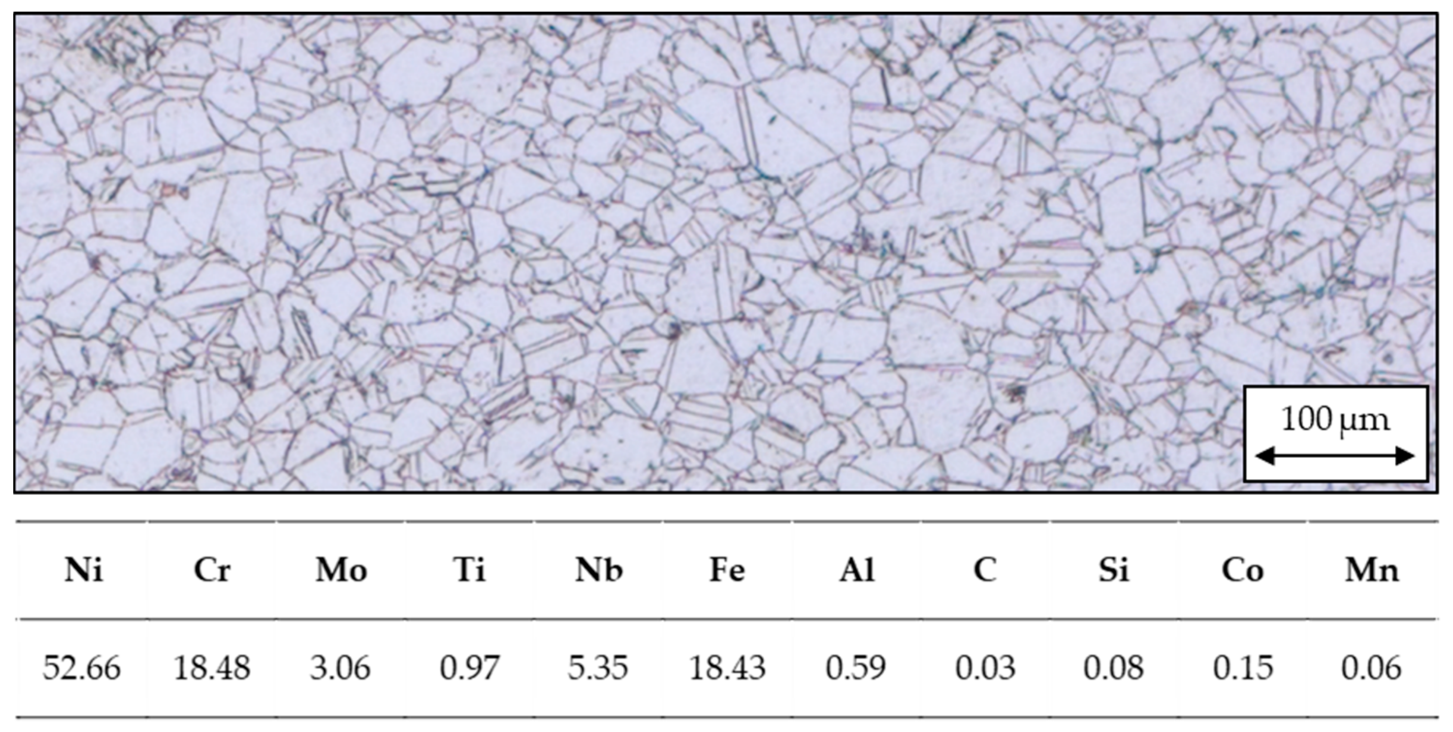
1.1. The Nickel-Base Alloy Inconel 718

Inconel 718 is considered to be one of the most widely used alloys for high-temperature applications in the aerospace industry due to its high tensile strength, fatigue strength and temperature resistance, which ensure that the alloy’s capability is maintained at temperatures up to 700 °C [1]. Hence, the mentioned properties qualify the material for applications in turbine blades, exhaust gas components, high-performance engines, reactors and turbochargers [2,3,4,5]. Furthermore, the nickel-base alloy is a proven material in the building of power plants and is applied in the oil and chemical industries. However, the described advantageous properties are equivalent to extensive challenges in machining. From the interaction of low thermal conductivity and high toughness, accelerated tool wear and reduced surface quality can be derived, which has to be emphasized in particular for drilling [1,6].

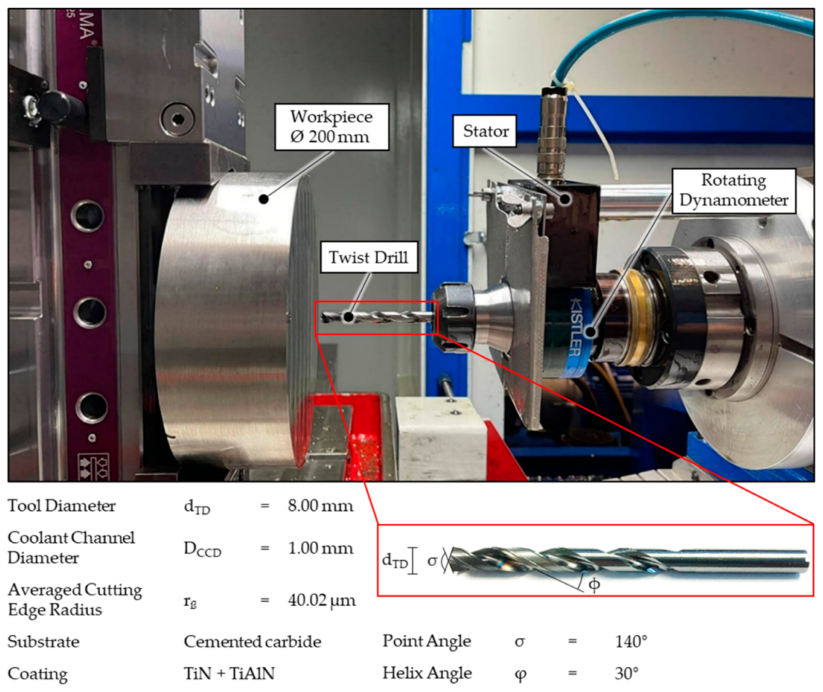
1.2. Characteristic Challenges and New Approaches to Drilling Inconel 718

Due to the material properties already mentioned, it is difficult to achieve an efficient process for drilling components made of the nickel-base alloy. Because of its additional high-temperature strength, toughness and creep resistance, the setting of productive and process-safe cutting parameters is very demanding. These prevailing circumstances during drilling favor high thermomechanical loads arising in the difficult-to-access cutting zone and leading to premature tool failure. The common signs of wear at the cutting edge are due to abrasion on the one hand, which is intensified by carbides, as well as by strength-enhancing precipitations in the microstructure. On the other hand, the alloy Inconel 718 is known for its adhesion tendency and its pronounced work hardening with further negative impact on tool life. The aforementioned thermomechanical load in the chip-formation zone also affects the workpiece quality by impairing surface integrity, typically in the form of white layers, leading to high tensile residual stresses, microcracks and thus, reduced fatigue strength in the highly stressed component. Therefore, the development and implementation of a favorable cooling strategy is essential for improving drilling processes by enhanced heat evacuation from the chip-formation zone [7,8,9,10,11,12].
In this context, Oezkaya et al. modified the flank face of twist drills by grinding a passage parallel to the cutting edge in favor of improved coolant flow between tool tip and the bore hole ground. Firstly, the applicability was researched numerically by computational fluid-dynamics simulations showing that the passage is filled with coolant flushing to crucial areas of the drill, leading to reduced temperatures at the cutting edges. Secondly, the finite element method was used to ensure that the stability and mechanical strength of the modified tool tip are retained. Afterwards, corresponding experiments on drilling Inconel 718 revealed a significantly increased drilling path as well as lower tool wear. Using the enhanced tool, higher cutting parameters could also be successfully achieved [13,14,15].

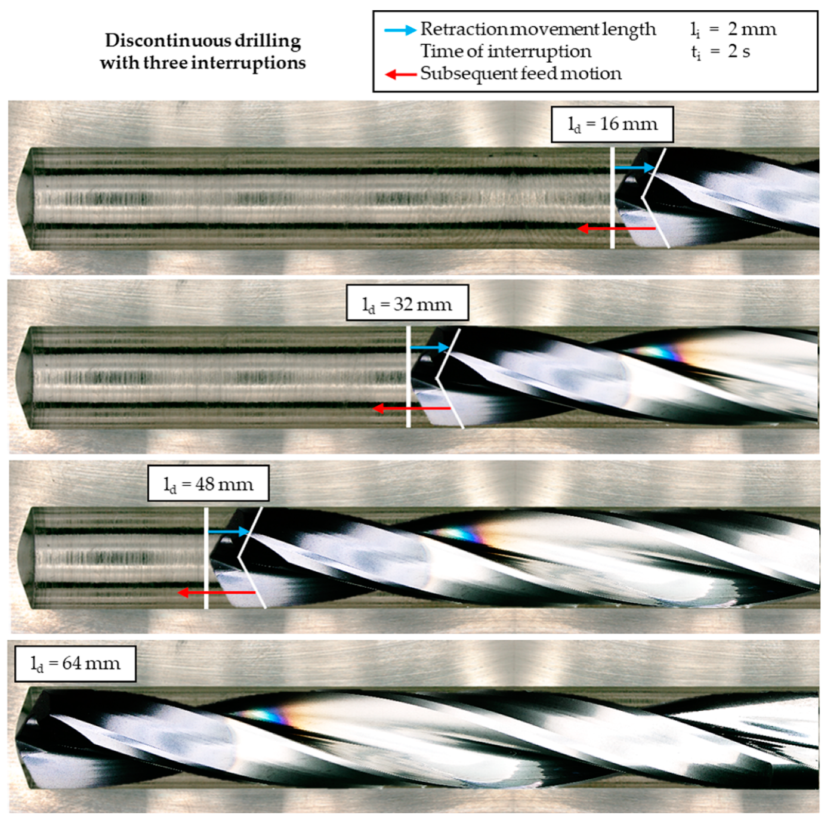
1.3. Further Development of the Conventional Process towards Discontinuous Drilling

In contrast to developing optimized tool geometries used in conventional drilling processes, the approach of discontinuous drilling was designed as a new process strategy to improve the machining of nickel-base alloys by inserting targeted interruptions into the feed motion and permitting a reliable coolant supply to the cutting edges. During these interruptions, the tool is retracted from the chip-formation zone, which leads to a wetting of the cutting edges with cooling lubricant. Simultaneously, the interruption enforces chip breaking and thus, intensive friction at the secondary shear zone due to the formation of ribbon chips is extenuated, which is coherent with reduced thermal load [16,17,18].
In order to distinguish the advanced process strategy from conventional drilling, first experimental studies were executed focusing on the influence of three interruptions and seven interruptions, respectively, on thermomechanical load seen over a drilling depth of ld = 64 mm. During the experiments, a twist drill with a diameter of dTD = 8 mm was used, cooled and lubricated by a specialized deep hole drilling oil. The setting of cutting parameters based on the scientific work of Beer leading to a cutting speed of vc = 25 m/min and a feed of f = 0.1 mm [19].
The experimental work on discontinuous drilling was carried out on the deep-hole drilling machine tibo KTE 40-1000 using the cutting oil Blaser Blasomill 10 D. The cooling lubricant is characterized by a viscosity of ν = 10 mm2/s and a density of ρ = 0.85 g/cm3, related to a temperature of T = 40 °C.
For the experimental analysis of drilling Inconel 718, a round specimen with a diameter of d = 200 mm and a thickness of t = 70 mm was used. The heat treatment included an annealing at a temperature of T = 980 °C and a subsequent three-step aging process at the temperatures T = 721 °C, T = 56 °C and T = 621 °C. The material’s chemical composition is presented in Figure 1, based on the inspection certificate of the manufacturer. The material hardness was measured over the diameter showing an average of H = 490 HV30. The tensile strength of the material is Rm ≈ 1404 MPa.
The experimental setup used in the initial experiments on discontinuous drilling is presented in Figure 2 and consists of the clamped specimen and the tool placed in the corresponding rotating dynamometer Kistler 9170A, which records the mechanical load in the form of feed force and drilling torque during the experiments.
Figure 3, exemplary for a process with three interruptions, illustrates the fundamental process idea of discontinuous drilling. The final drilling depth, ld = 64 mm, is interrupted periodically after 16 mm at the marked points of the currently reached drilling depth. Afterwards, the retraction movement of li = 2 mm, contrary to the direction feed motion, occurs and the tool’s position is maintained for ti = 2 s to allow a cooling of the cutting edges by flushing with the cooling lubricant. After this time interval, the feed motion continues. The approach described can be transferred to discontinuous drilling with seven interruptions performed with interruptions after every 8 mm of feed motion.
During drilling, the different process strategies were opposed to each other primarily by analyzing the mechanical load acting on the tool and the flank wear occurring. In this context, it can be stated firstly, that for all examined process strategies, the tools were able to achieve a drilling path of Lf = 2560 mm for the cutting parameters used.
Figure 4 describes the measured drilling torque Mb and feed force Ff of the respective process strategies, which are mostly on a similar level, seen over the drilling path.
Apart from a outlier due to an error during measurement at the stage Lf = 768 mm for continuous drilling, the mechanical load for all examined process strategies only slightly and uniformly increases due to developing tool wear.
However, by measuring and comparing the tool’s flank wear after a periodic interval of Lf = 256 mm for every process strategy examined, slight differences are apparent, which is shown in Figure 5.
At the end of the drilling path, the width of flank wear VBmax for continuous drilling is 13% higher than the corresponding value of discontinuous drilling with seven interruptions.
Therefore, reduced thermal loads can be suspected, showing beneficial influence on the development of tool wear since the mechanical load is mostly uniform for all process strategies. Thus, the presentation of the first experimental results underlines the potential of a discontinuous feed motion integrated in the process of drilling Inconel 718 [20]. The highlighted improvements in decreased tool wear also indicate that a potential influence of the targeted supply of cooling lubricant on the process-related microstructure of drilled holes can be expected. The required metallographic analyses for achieving information about the present grain structure and microhardness are discussed in the following section.

2. Metallographic Analysis of Microstructure and Microhardness

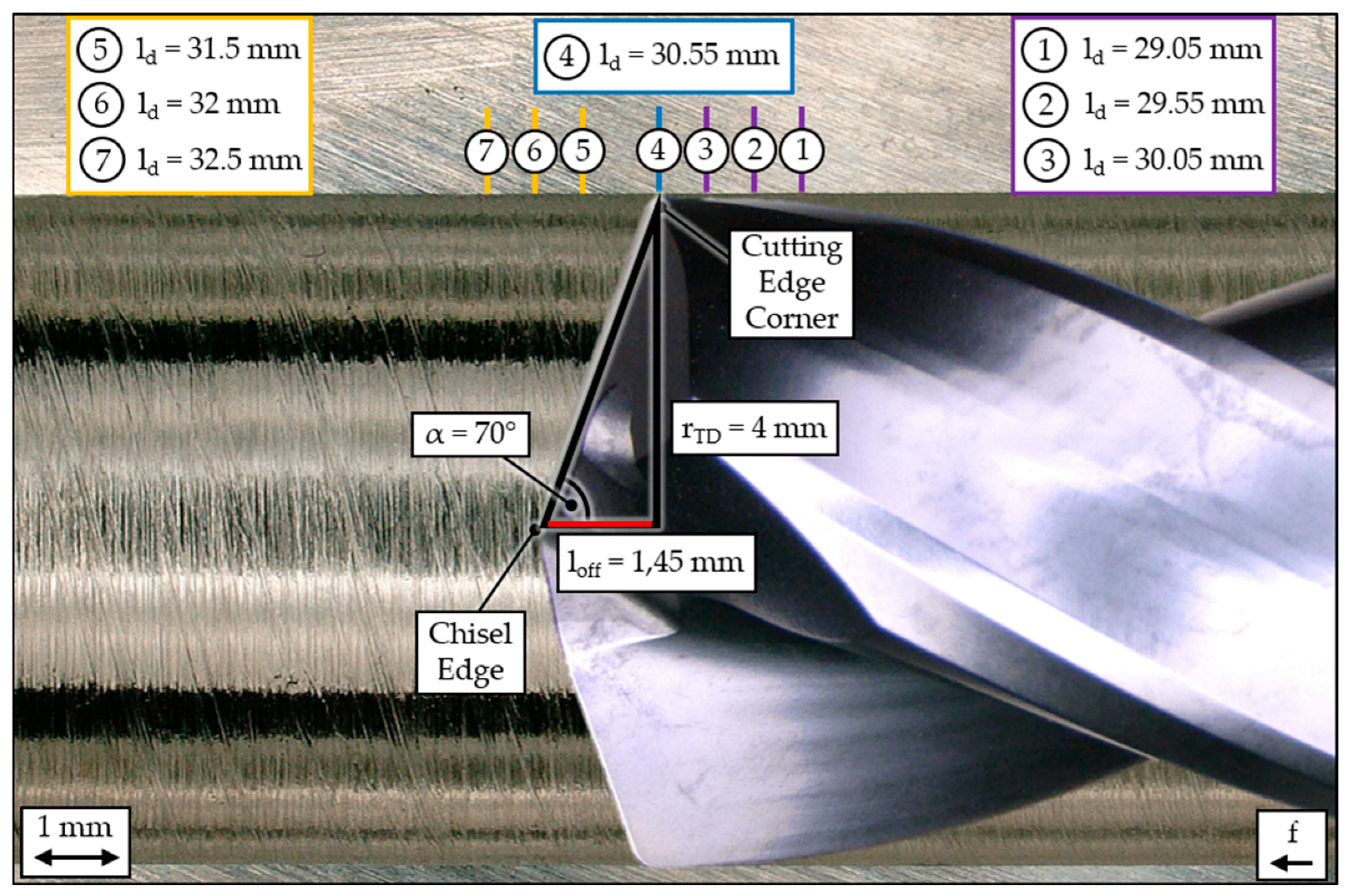
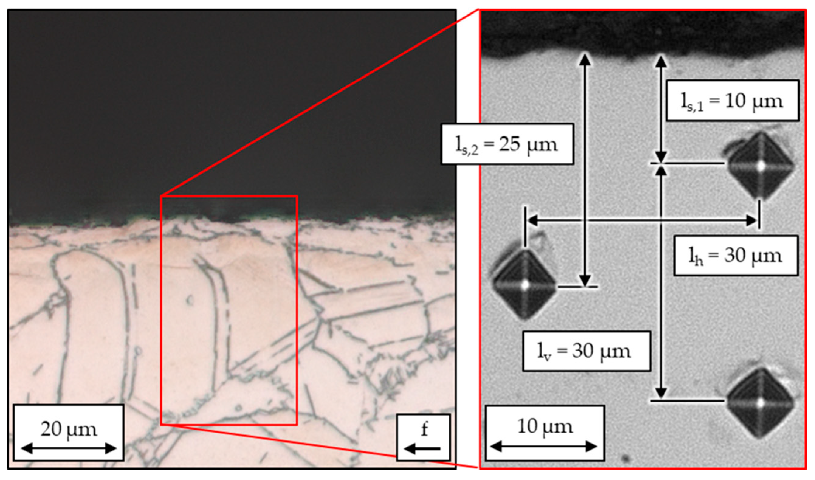
Preparation in Favor of Metallographic Analysis

Subsequent to the experiments, particular bore holes, after a drilling path of Lf = 1280 mm for each process strategy examined, were machined out of the material and prepared for analyzing the process-related microstructure. The drilling depth ld = 32 mm was selected as the central point for defining the measurements, since for both the discontinuous drilling with three interruptions and with seven interruptions, the feed was paused at this location, allowing the cooling lubricant to act on the cutting edges. Thus, a comparison of the adapted process strategies and continuous drilling is feasible, aiming at referring to different thermal loads. The isolated bore holes are embedded, polished and finally, etched to expose the microstructure. For the etching, a mixture of nitric acid, hydrochloric acid and acetic acid was used to carve out the process-specific formation of grain boundaries at the surface area of each specimen. Therefore, Figure 6 describes the fundamental procedure to identify reasonable locations for measuring microhardness and create microscopic images of the grain structure.
Starting from the central point of feed interruption, located at the drilling depth ld = 32 mm, it has to be considered that there is a deciding offset between the chisel edge and the cutting-edge corner where chip formation takes place and the thermal load is transferred into the surface of the bore hole. By calculating this offset length as loff = 1.45 mm, the location of the cutting-edge corner at the moment of interruption is identified as ld = 30.55 mm. This central drilling depth serves as the boundary between the area machined before interrupting the feed and the area in contact with the cutting edge following the interruption of the feed, respectively. Concerning the measurements of microhardness, both areas consist of three points of measurement each to guarantee a solid amount of data, enabling a resilient comparison of microhardness in relation to the process strategy. Another measurement is located directly at the point of interruption to analyze the potential effects of transitions in microhardness due to the adapted process strategy. The principle behind the following analyses of microstructure and microhardness is illustrated in Figure 7.
The later presented microscopies were made with the optical microscope Zeiss Axio Imager 2, whereas the measurements of Vickers microhardness were made with the testing device Shimadzu HMV-G. The measurement of microhardness was at the direct surface area up to a maximum distance of bS = 150 µm to the bore hole wall. This was defined corresponding to Beer, who analyzed the influence of drilling on the microstructure of Inconel 718 in this region. The analysis of every bore hole consists of ten points of measurement arranged in two offset lines, as shown in Figure 7. The starting point of measurement closer to the bore hole wall is positioned with a distance to surface of ls,1 = 10 µm, whereas the starting one of the offset line has a pitch to the surface of ls,2 = 25 µm. This placement does not conform to standards but is necessary to receive insights into microhardness in the area of potential transformation of the microstructure, which is observed up to 20 µm within the surface area when the material is drilled with twist drills [13]. The following measuring points, on the other hand, are carried out with a standardized horizontal measuring distance of lh = 30 µm and lv = 30 µm, representing the vertical distance between the two lines, respectively. The intender loads the material with a test force F = 245.2 mN over a duration of t = 10 s. Comparative measurements of the material’s hardness in the initial condition were placed within a distance of 2.9 mm to the surface area. By taking into account ten arranged measurements, an average materials hardness of 560 HV0.025 is indicated.

3. Results of Metallographic Analysis

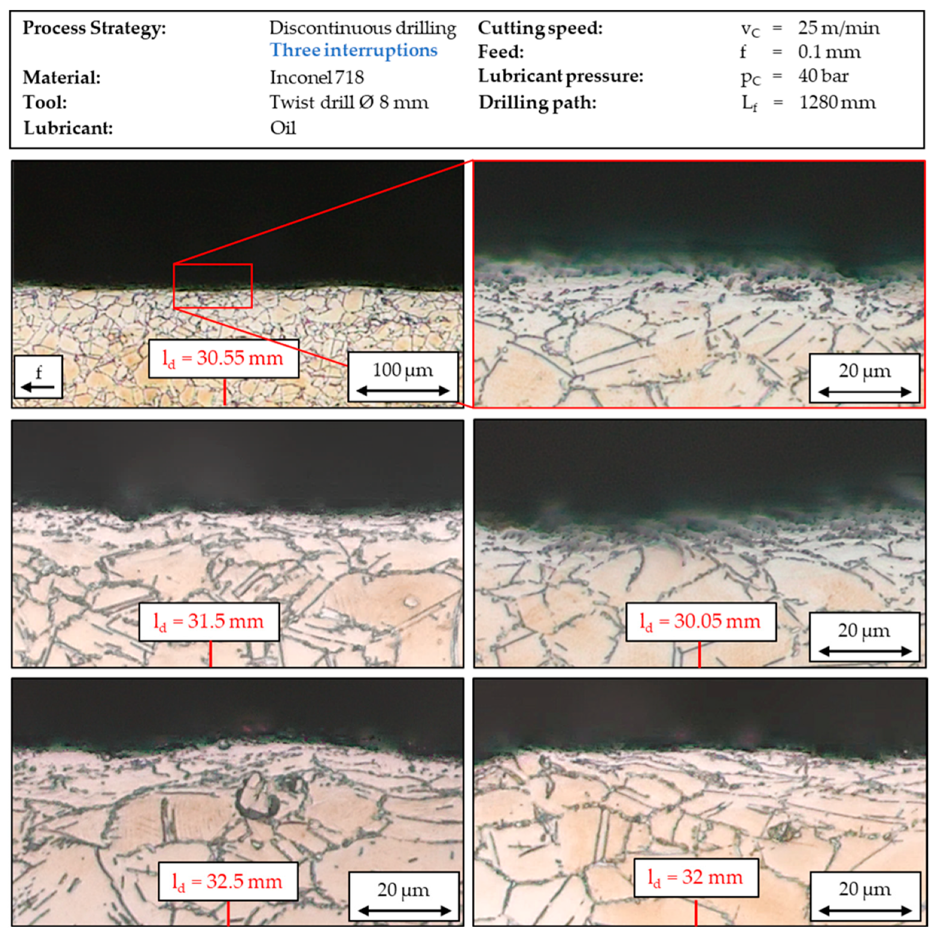
3.1. Analysis of Process-Related Microstructure

In terms of suspected reduced thermal loads during drilling with interruptions of the feed, decreased tool wear has already been proven and a homogeneous microstructure of the bore holes from a discontinuous process should become apparent.
As a kind of initial state, Figure 8 shows the etched surface of a bore hole resulting from a conventional drilling process with continuous feed motion. The pictured microscopies reveal process-induced transformations in the microstructure in the form of characteristic white layers with a thickness of almost t = 10 µm at the central location of measurement at ld = 30.55 mm. Those layers are formed within the grains of the nickel-base alloy and are characterized by a highly refined grain structure. The rise of white layers with their typical fine-grain structure is very critical for components made of nickel-base alloys and has to be avoided because this kind of microstructure decreases the service life of technical parts dramatically.
On the one hand, this transformation is due to the complex interaction between mechanical and thermal load in the chip-formation zone and, on the other hand, due to rapid cooling afterwards by lubricant that is evacuated through the flutes. The material reacts with recrystallization on this alternating load after facing the mentioned high temperatures at the cutting-edge margins combined with high friction at the land of the drill, which has a major impact on thermal load. Moreover, tool wear is connected to higher temperatures, because there was higher tool wear detected in continuous drilling.
The first impression of present microstructure requires further analysis in the area around the measurement point to intensify scientific value and later, to support a funded comparison with the discontinuous process strategies. In this regard, additional pictures were taken in front of and behind a drilling depth of ld = 30.55 mm, respectively, where a potential influence on the interruptions could be identified. However, concerning the continuous drilling, further recrystallization has already been discovered in the area of ld = 30.05 mm and moreover, in front of the central measurement point, specifically pointed out for ld = 31.5 mm, ld = 32 mm and ld = 32.5 mm. Although those observed layers do not range consistently over the displayed edge zone, a thermal load acting in the chip-formation zone and causing phase transformations already at a relatively low cutting speed of vc = 25 m/min is recognizable and of representative value.
By analyzing the present microstructure after a drilling path of Lf = 1280 mm for continuous drilling following the described procedure, also illustrated in Figure 6, a resilient schema of measurement is created, transferable on analyzing the discontinuous processes. Hence, the bore hole of discontinuous drilling with three interruptions after a drilling path of Lf = 1280 mm was also prepared for analyzing the corresponding microstructure, the results of which are presented in Figure 9, and certain improvements regarding the prevention of potential phase transformation due to thermal load are verifiable. In contrast to continuous drilling, no significant transformations in the microstructure were found in the particular surface areas where the feed motion was interrupted; those areas are equivalent to those analyzed during the conventional drilling of Inconel 718. By including these additional results, the assumption that inserting interruptions into the drilling process of the nickel-base alloy leads to a reduced thermal load is even more emphasized. After pointing out the beneficial impact on tool wear, a potential influence on surface integrity has to be expected.
Since there are already improvements located at ld = 30.05 mm before the second point of interruption is reached, there also have to be potential reduced process temperatures resulting from the first interruption of the feed at ld = 16 mm with a maintained benefit on bore hole microstructure.
In order to complete the analysis of the process-related microstructure of bore holes drilled in Inconel 718, the holes resulting from a discontinuous process strategy with seven interruptions of feed were also separated and embedded to allow further examination. Figure 10 provides insights into the characteristic microstructure. Again, the interruptions show a beneficial influence on the surface area of the bore hole for all measurements. The described impact of alternating loads on microstructure leading to recrystallizations is almost absent under these circumstances, since the tool temperature is potentially reduced due to the rewetting of the cutting edges during the interruptions. The microscope images illustrate that the characteristic austenitic microstructure is not transformed into fine-grained white layers but maximally into a martensitic microstructure, exclusively due to mechanical impact. The grain structure is preserved from white layers in the bore hole’s surface area and thus, decreasing workpiece quality can be prevented with the improved drilling concept. When comparing the microscope images of the bore holes made by discontinuous drilling with three interruptions with discontinuous drilling supported by seven points of pausing the feed and wetting the cutting edges, there are no significant differences detectable. Regarding this aspect of the analysis, further, in particular numerical investigations have to be performed to optimize the effective number of interruptions needed to avoid transformations of microstructure in relation to increased productivity.

3.2. Analysis of Process-Related Microhardness

The formation of white layers, especially in continuous drilling, is usually accompanied by an increase in hardness in the surface area up to 50% above the material’s basic hardness, due to tensile residual stresses that are undesirable in applications of Inconel 718 [13].
The evaluation of the measurements is presented in Figure 11 and was carried out according to the procedure presented in advance. The analysis of the material’s microhardness for the three examined process strategies is composed of three averaged measuring points each for the area before interrupting the feed (points 1–3), and the area after the interruption of feed appeared (points 5–7), respectively, in accordance with the methodology of microscopic analysis and is presented in separate diagrams.
The figure points out increased hardness in the immediate surrounding of the bore hole wall, especially in discontinuous drilling with three interruptions. With a value of 651 HV0.025 at bs = 0.1 mm, the microhardness is nearly 16% above the averaged value of the common microhardness of the material in its initial condition, speaking of the drilling depth before the feed motion is paused and a cooling and lubrication of the cutting edges is initiated. Since the increase of hardening at this drilling depth is higher than for the drilling depth after the interruption of feed happened for discontinuous drilling with three interruptions, a positive impact on hardness could be assumed due to decreased process heat. However, a distinct correlation between adapted coolant supply and a reduced hardness increase is difficult to detect, especially because, at the area before the feed interruption, the hardness in continuous drilling is the closest to the hardness of the surrounding material. Besides the thermal impact of the drilling process, mechanical deformation with subsequent strain hardening can also be suspected as a major influence on hardness at the bore wall.
In general, the greatest deviation to continuous drilling would have been expected at the exact location of interrupting the feed motion and moreover, the directly following part of the bore hole, since this matches the drilling depth where a wetting of the cutting edges with lubricant takes place immediately, and a cooling effect on the cutting edge should have happened, causing a direct influence on the microstructure. The values of Vickers hardness are mostly at the same level for each of the process strategies examined, especially for the examined part of the bore hole wall that is drilled after interrupting the feed. Based on the analysis of microhardness, new approaches have to be aimed at designing the interruption of the feed in terms of duration and distance between hole bottom and tool tip, to additionally clarify and potentially minimalize the thermal impact on hardening.

4. Conclusions

The already suggested potential benefit of a discontinuous drilling process on tool life due to reduced thermal loads becomes amplified by the additional analysis of microstructure. First, microscopic images of longitudinal sections separated from bore hole walls illustrate the appearance of white layers during the conventional drilling of Inconel 718. In contrast to this result, a positive impact on phase transformation in the material during discontinuous drilling is revealed. The microstructure examined at the drilling depths subsequent to the point of feed interruption is free from thermal-induced phase transformations in both discontinuous processes. This can be attributed to the occurring retraction movement of the twist drill allowing a wetting of the cutting edge, since this is missing during conventional drilling, where white layers were detected in the relevant areas. Additional measurements of microhardness in the crucial areas of the bore hole did not reveal significant differences between the process strategies, since this property of surface integrity is more influenced by mechanical load than thermal load.

Author Contributions

Investigation, T.W.; Methodology, T.W.; Project administration, I.I. and D.B.; Validation, I.I.; Visualization, T.W.; Writing—original draft, T.W.; Writing—review & editing, I.I. and D.B. All authors have read and agreed to the published version of the manuscript.

Funding

This paper consists of research results achieved within the project “Simulation and optimization of the coolant flow to reduce the thermal tool load during discontinuous drilling of Inconel 718”, which is kindly funded by the German Research Foundation (DFG)—Project Number: 439920593.

Data Availability Statement

The data presented in this study are available on request from the corresponding author.

Conflicts of Interest

The authors declare no conflict of interest.

References

  1. Donachie, M.J.; Donachie, S.J. Superalloys—A Technical Guide, 2nd ed.; ASM: Geauga County, OH, USA, 2008. [Google Scholar]
  2. Heubner, U. Nickelwerkstoffe und Hochlegierte Sonderedelstähle, 5th ed.; Expert Verlag: Renningen, Germany, 2012. [Google Scholar]
  3. Bürgel, R.; Maier, H.-J.; Niendorf, T. Handbuch Hochtemperatur-Werkstofftechnik, 4th ed.; Vieweg-Teubner Verlag: Wiesbaden, Germany, 2011. [Google Scholar]
  4. Steffens, K.; Wilhelm, H. Werkstoffe, Oberflächentechnik und Fertigungsverfahren für die nächste Generation von Flugtriebwerken; Deutscher Luft-und Raumfahrtkongress: Hamburg, Germany, 2000. [Google Scholar]
  5. Choudhury, I.A.; El-Baradie, M.A. Machinability of nickel base super alloys. J. Mater. Process. Technol. 1998, 77, 278–284. [Google Scholar] [CrossRef]
  6. Wessels, T. Bohren in Ph.D. Titan-und Nickelbasislegierungen; TU Braunschweig: Braunschweig, Germany, 2007. [Google Scholar]
  7. Günther, C.; Böttger, H.; Köhler, S. Hochgeschwindigkeitsbearbeitung von Nickelbasislegierungen. MM-Masch. Das Ind. 1998, 104, 44–49. [Google Scholar]
  8. Veselovac, D. Process and Product Monitoring in the Drilling of Critical Aero Engine Components. Ph.D. Dissertation, RWTH Aachen, Aachen, Germany, 2013. [Google Scholar]
  9. Rasti, A.; Sadeghi, M.H.; Farshi, S.S. An investigation into the effect of surface integrity on the fatigue failure of AISI 4340 steel in different drilling strategies. Eng. Fail. Anal. 2019, 95, 66–81. [Google Scholar] [CrossRef]
  10. Mütze, H. Beitrag zur Zerspanbarkeit hochwarmester Werkstoffe. Ph.D. Dissertation, Technische Hochschule Aachen, Aachen, Germany, 1967. [Google Scholar]
  11. Klocke, F.; Sangermann, H.; Krämer, A.; Lung, D. Influence of a high-pressure lubricoolant supply on thermo-mechanical tool load and tool wear behaviour in the turning of aerospace materials. Proc. Inst. Mech. Eng. Part B J. Eng. Manuf. 2011, 225, 52–61. [Google Scholar] [CrossRef]
  12. Zhang, L.; Wagner, T.; Biermann, D. Optimization of cutting parameters for drilling Nickel-based alloys using statistical experimental design techniques. In Proceedings of the 37th International MATADOR Conference, Manchester, UK, 25–27 July 2012. [Google Scholar]
  13. Oezkaya, E.; Bücker, M.; Strodick, S.; Biermann, D. A thermomechanical analysis leading to a novel flank face design providing longer tool lives for tools used in the drilling of Inconel 718. Int. J. Adv. Manuf. Technol. 2019, 102, 2977–2992. [Google Scholar] [CrossRef]
  14. Oezkaya, E.; Bücker, M.; Biermann, D. Simulative analyses focused on the changes in cutting fluid supply of twist drills with a modified flank face geometry. Int. J. Mech. Sci. 2020, 180, 105650. [Google Scholar] [CrossRef]
  15. Bücker, M.; Oezkaya, E.; Hensler, U.; Biermann, D. A new flank face design leading to an improved process performance when drilling high-temperature nickel-base alloys. In Proceedings of the 20th Machining Innovations Conference for Aerospace Industry 2020 (MIC 2020), Hannover, Germany, 2 December 2020. [Google Scholar]
  16. Brinksmeier, E.; Pecat, O.; Rentsch, R. Quantitative analysis of chip extraction in drilling of Ti6Al4V. CIRP Ann. Manuf. Technol. 2015, 64, 93–96. [Google Scholar] [CrossRef]
  17. Deyuan, Z.; Lijiang, W. Investigation of chip in vibration drilling. Int. J. Mach. Tools Manuf. 1998, 38, 165–176. [Google Scholar] [CrossRef]
  18. Paulsen, T.; Pecat, O.; Brinksmeier, E. Influence of Different Machining Conditions on the Surface Properties of Drilles TiAl6V4. Procedia CIRP 2016, 46, 472–475. [Google Scholar] [CrossRef] [Green Version]
  19. Beer, N. Systematische Untersuchung von Vollhartmetall-Wendelbohrern zum Bearbeiten von Inconel 718; Vulkan-Verlag GmbH: Dortmund, Germany, 2015. [Google Scholar]
  20. Wolf, T.; Iovkov, I.; Biermann, D. Discontinuous Drilling of Inconel 718. In Proceedings of the 2nd International Conference on Thermal Issues in Machine Tools, ICTIMT 2021, Praque, Czech Republic, 20 April 2021. [Google Scholar]
Figure 1. Microstructure (top) and chemical composition (bottom) of Inconel 718 (in wt-%).
Jmmp 05 00043 g001
Figure 2. The experimental setup in detail and an overview of the tool properties.
Jmmp 05 00043 g002
Figure 3. The discontinuous drilling process using the example of the three interruptions.
Jmmp 05 00043 g003
Figure 4. The mechanical load occurring at the cutting edge, seen over the drilling path Lf.
Jmmp 05 00043 g004
Figure 5. Development of flank wear over the drilling path.
Jmmp 05 00043 g005
Figure 6. Longitudinal section analyzed at the middle of drilling depth ld = 32 mm.
Jmmp 05 00043 g006
Figure 7. Longitudinal section analyzed at the middle of drilling depth ld = 32 mm.
Jmmp 05 00043 g007
Figure 8. Characteristic bore hole wall microstructure resulting from drilling conventionally in Inconel 718.
Jmmp 05 00043 g008
Figure 9. Improvement on microstructure due to a discontinuous drilling process with three interruptions.
Jmmp 05 00043 g009
Figure 10. Improvement on microstructure due to a discontinuous drilling process with seven interruptions.
Jmmp 05 00043 g010
Figure 11. Impact of a discontinuous drilling strategy on microhardness.
Jmmp 05 00043 g011
Publisher’s Note: MDPI stays neutral with regard to jurisdictional claims in published maps and institutional affiliations.

