Article

Effect of Electric Current on SPS Densification of Spherical Copper Powder

1
ICB, UMR 6303 CNRS/Université de Bourgogne Franche-Comté, 9 Avenue Alain Savary—BP 47870, 21078 Dijon, France
2
SIMAP, UMR 5266 CNRS/Université de Grenoble-Alpes, 1130 Rue de la Piscine—BP 75, 38402 Saint-Martin-d’Hères, France
*
Author to whom correspondence should be addressed.
J. Manuf. Mater. Process. 2021, 5(4), 119; https://doi.org/10.3390/jmmp5040119
Submission received: 3 October 2021 / Revised: 27 October 2021 / Accepted: 2 November 2021 / Published: 5 November 2021

Abstract

:
When a current is involved, as in spark plasma sintering, metallic powders are heated by the Joule effect through both tool and specimen. Other mechanisms might occur, but it is difficult to separate the role of the temperature from the role of the current inside the sample as, in most cases, the two parameters are not controlled independently. In this paper, the consolidation and the densification of a pure copper powder were studied in three configurations for obtaining different electric current paths: (i) current flowing through both the powder and the die, (ii) current forced into the powder and (iii) no current allowed in the powder. Electrical conductivity measurements showed that even low-density samples displayed higher conductivities than graphite by several orders of magnitude. FEM simulations confirmed that these copper specimens were mainly heated by the graphite punches. No modification of the microstructure by the flow of current could be observed. However, the absence of current in the specimen led to a decrease in densification. No significant temperature difference was modeled between the configurations, suggesting that differences are not linked to a thermal cause but rather to a current effect.

1. Introduction

Spark plasma sintering (SPS) shows high performance in sintering metallic powders in a short time. Tokita first suggested that the formation of sparks and plasma enhanced consolidation and densification mechanisms [1], but the lack of evidence for spark discharge and plasma resulted in further research on the mechanisms occurring in SPS devices. Unconventional necks between particles were attributed to local overheating at the contact area [2,3], as well as the occurrence of spark discharges [4,5] or the Branly effect [6]. Ratzker et al. [7] observed that under an electric current, the compressive creep rate of pure copper increased, but there was no evidence that the electric current affected the microstructure or enhanced the reduction of powder surface area [8]. Hulbert et al. [9] concluded, using various in situ techniques, that there was no plasma during the SPS process. The comparison between SPS and conventional sintering processes such as HP (hot pressing) led to conflicting conclusions: differences [10,11,12,13] as well as the absence of differences [14,15,16,17] between the two processes. However, it seems that specific conditions must be fulfilled in order to show any current effect. Saunders et al. [18] affirmed that the formation of plasma cannot be excluded when higher voltages are employed. In fact, the conditions for plasma formation depend on the electrical and mechanical properties of the materials to be sintered [19]. Most authors agree in considering that the current effects (plasma and/or discharge) are expected to occur between particles that are not in contact [5] or at the beginning of the process when the contact area between particles is very low [20]. Collet et al. [21] observed no specific current effect during the consolidation stage of copper powders at 4 MPa. In addition, Collard et al. [22] showed that heat conduction made local overheating unrealistic in metallic powders below 100 µm in size. Consequently, copper samples could be considered as acting only as a heating element, as in the study by Anselmi-Tamburini et al. where the current distribution in copper parts was modeled [23]. Nevertheless, the material may not exhibit a high value of electrical conductivity, causing the current to flow preferentially through the die and preventing any current effect. Trapp et al. showed that the electrical resistivities of as-received powders (with a thin oxide layer) could be several orders of magnitude higher at lower pressures compared to those of etched powders [24]. The current effect therefore depends on the relative conductivities of the sample and the die and their dependence on temperature. This raises two questions: (i) do copper samples behave as heating elements throughout the SPS process and (ii) does the electric current though the powder affects the consolidation and densification? In order to answer these questions, copper powder will be sintered in three configurations for obtaining three different electric current paths: the standard SPS configuration (St) in which the current flows through both the powder and the die, a second configuration in which the current is forced (FC) into the powder and a third in which no current (NC) is allowed in the powder. The experimentally obtained dependency of the effective conductivity of copper samples on temperature and relative density will be used, together with simple FEM electrical–thermal modeling, in order to analyze and discuss the results.

2. Materials and Methods

TEKMAT Cu-38 (Tekna) copper powder prepared by the plasma method was used. This powder consisted of 25 µm spherical particles (Figure 1a), with 80% of particles formed of coarse grains (nearly monocrystalline) and the remainder of small grains (Figure 1b. The oxygen content was low (0.041 wt.%). For this reason, an oxide of only a few nm thickness, described more in detail in [18], covered the particle surface.
The powder (around 17 g) was sintered using an HPD 10 device (FCT Systeme, Germany). SPS sintering was performed under vacuum (2 × 10⁻⁵ bar). For each experiment, the die (with 30 mm inner diameter) was surrounded by carbon felt in order to limit thermal losses, and a graphite foil was inserted between the powder and the die/punches. Thermal cycles were performed using a constant heating rate (50 °C·min−1) up to 900 °C, without dwell time, followed by natural cooling. The SPS cycles were interrupted at 500 °C or 700 °C to observe the progress of consolidation and densification. A 4 MPa pressure was generally applied during the whole cycle, to ensure electrical contact between the SPS assemblies and to limit the amount of plastic deformation. Two additional experiments were performed with a 28 MPa pressure in order to intensify the effect of pressure. A non-pulsed current with a pattern of 20:0:1:0 (t-on: t-off: n-pulse: t-pause) was used. The displacement of the punches was continuously recorded during the SPS experiments to evaluate the sample shrinkage.
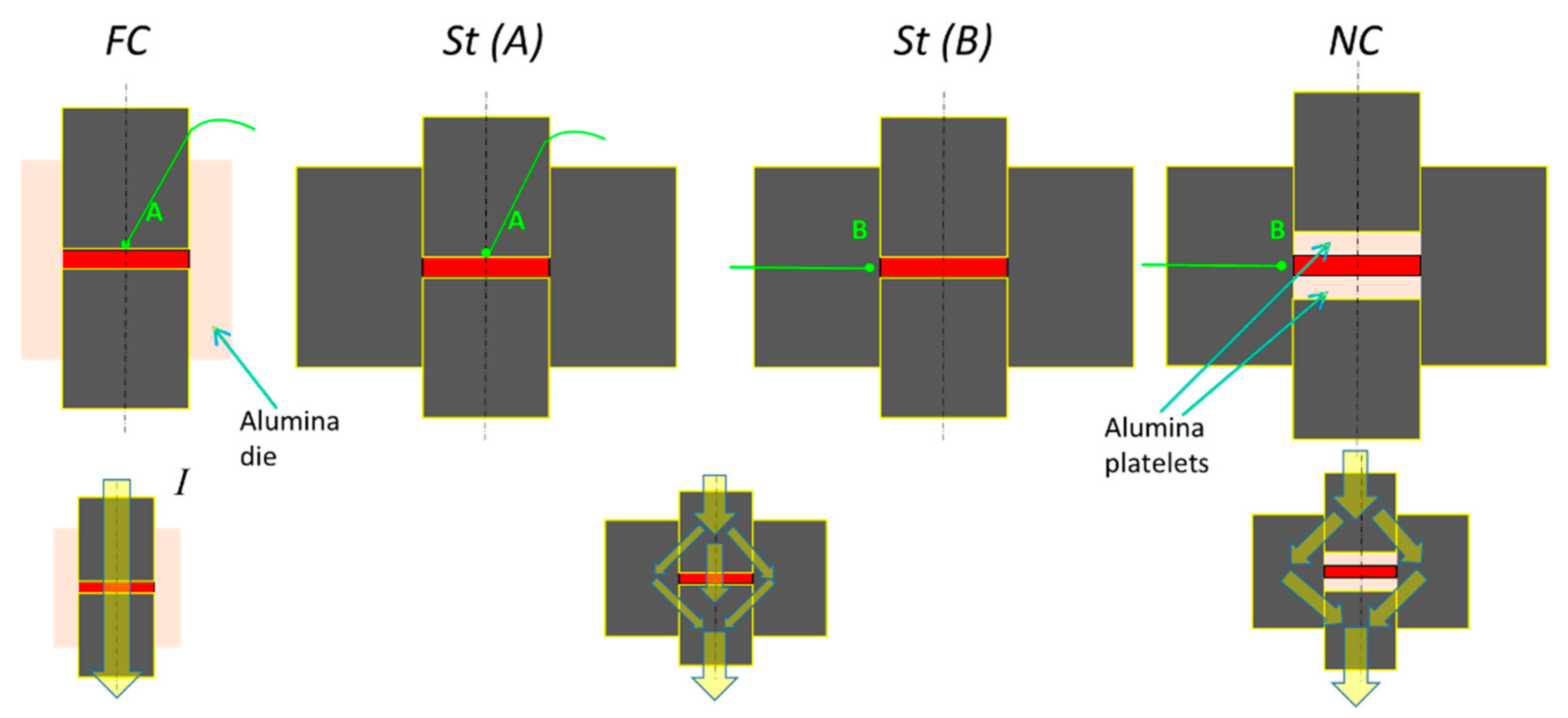
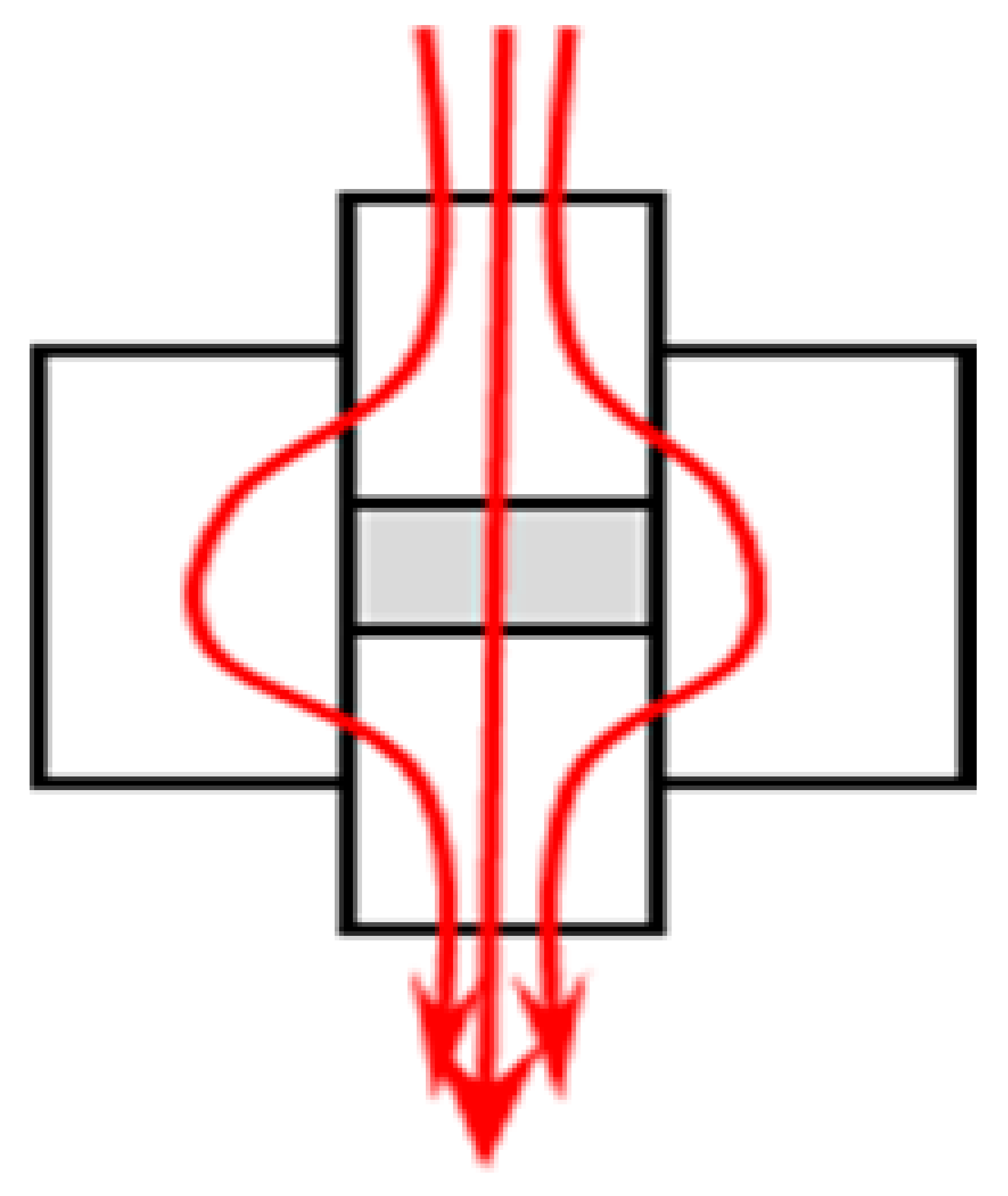
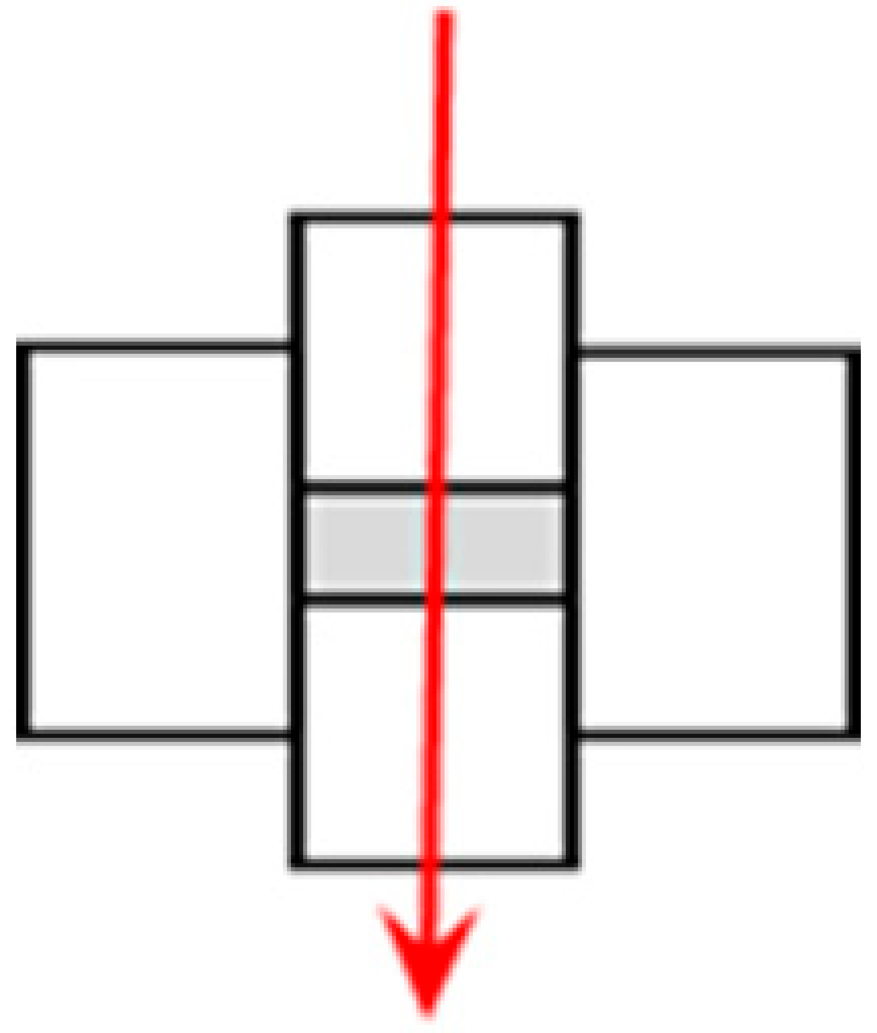
Different set-ups were used for controlling the current path in the die and the sample, in order to analyze the effect of the current (Figure 2). For comparing standard SPS conditions (St) and heating with no current through the powder (NC), the same die and punches were used: a graphite (Mersen 2333) die with an outer diameter of 90 mm. The thermocouple was inserted through the die at 2 mm from the sample. In the case of NC, two alumina platelets with a diameter of 30 mm and a thickness of 5 mm were inserted between the punches and the sample, to force the current to pass through the graphite die. For the forced current (FC) case, an isolating alumina die with an outer diameter of 50 mm was used. The thermocouple was inserted through the punch in order to prevent the alumina die breaking. It was placed in contact with the graphite foil, 0.4 mm above the sample. To ensure a significant comparison between St and FC configurations, a graphite die (outer diameter of 90 mm) with the same thermocouple location was used. The other parameters were kept constant: the same sample diameter (inner die diameter of 30 mm), the same die height (50 mm) and same punch height (35 mm). The final sample height was typically 3.5 to 5 mm.
The sample final densities (df) were evaluated after sintering using the Archimedes method in water and the reference copper density (8.96 g·cm−3).
The punch displacement was continuously recorded during the experiment and corrected for the device thermal expansion, which was measured by performing an identical cycle with a dense copper sample for each experiment. This enabled calculation of the density evolution using the recorded punch displacement, according to:
d = d f L f Δ L L f Δ L f ,
where Δ L and ΔLf are the corrected displacements obtained from the punch displacement at time t and the final time, respectively. The initial density d0 was calculated from the same equation with Δ L = 0 .
Fractured samples were observed with a JEOL 6400F scanning electron microscope (SEM). The electrical conductivities of the sintered samples were measured on the flat surface of the specimens with a SIGMATEST® 2.069 apparatus (0.5–65 MS·m−1 probe range) based on electromagnetic measurements (induced current).

3. Results

Table 1 summarizes the experimental conditions for the different samples and gives the measured values of the final density and sample height.
The initial densities obtained after a cycle at 4 MPa in the graphite die were close to each other (around 58.5%). The initial density obtained in the alumina die at the same pressure was higher (60.6%). When the pressure was increased to 28 MPa, the initial density was approximately 63%.
The presented densification curves were obtained from the measured punch displacements corrected for the device thermal expansion and the final measured specimen density (Archimedes) and dimensions. The device thermal expansion was measured by performing an identical cycle with a dense copper sample for each experiment.

3.1. Comparison of Standard SPS Conditions with Different Thermocouple Positions (StA and StB)

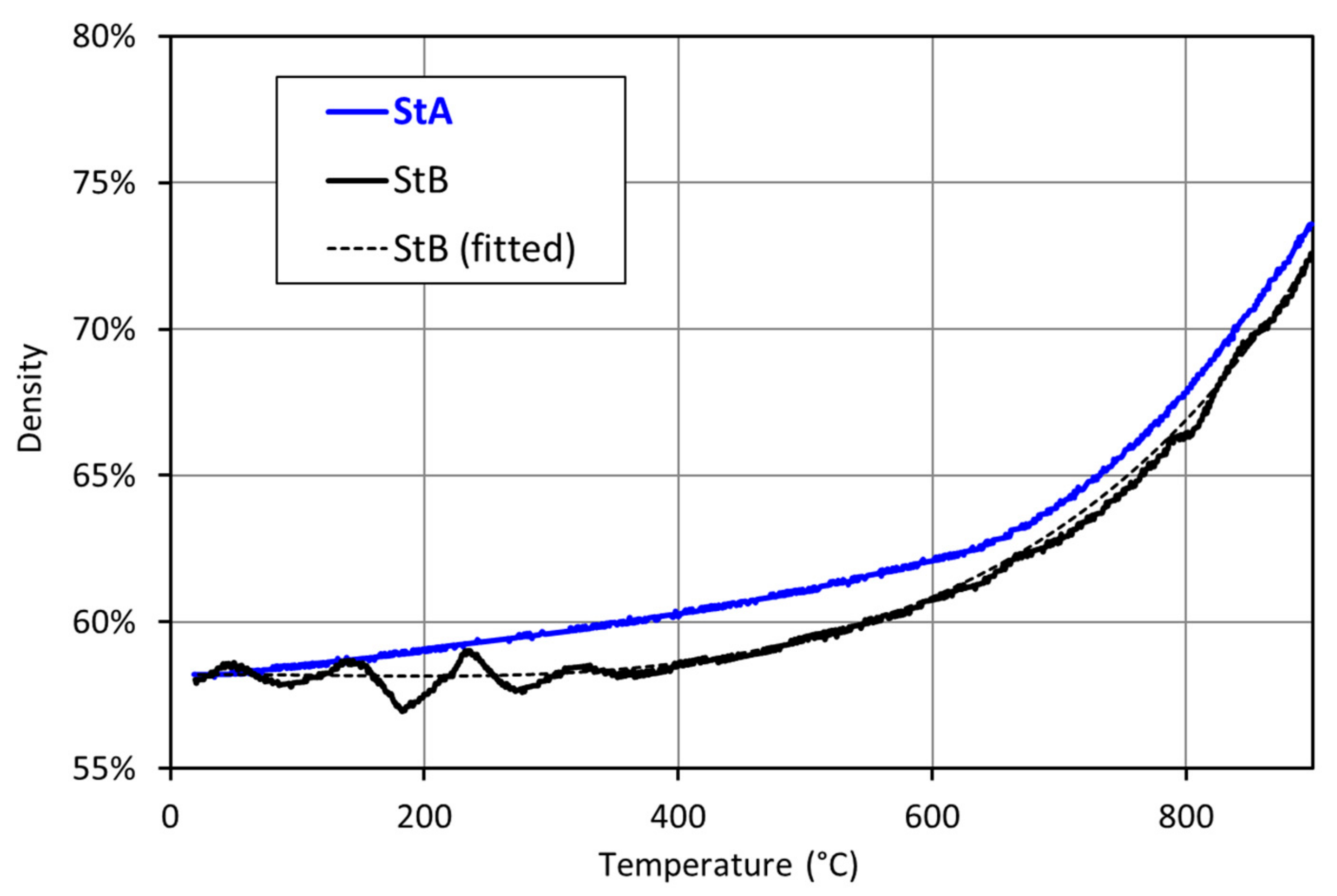
Figure 3 compares the densification curves obtained in the graphite die standard configurations (St) for the two thermocouple locations (A and B). The densification curve StB shows some fluctuations at the beginning of the cycle which originate from a temperature regulation problem. A fitted curve (dashed line) is added to facilitate comparison with StA and for use in the following analysis.
The StA curve shows strong densification from low temperatures. This will also be observed later for another configuration. It suggests a higher sample temperature in the set-up, leading to a higher final density for the same measured temperature when starting from the same initial density (Table 1). This illustrates the sensitivity to thermocouple position and justifies the choice of two different St references for FC (which does not allow the position B in the alumina matrix) and for NC (for which the alumina platelets would have distorted the temperature evaluation in position A).

3.2. Comparison between Standard SPS (StA) and Forced Current (FC) Conditions

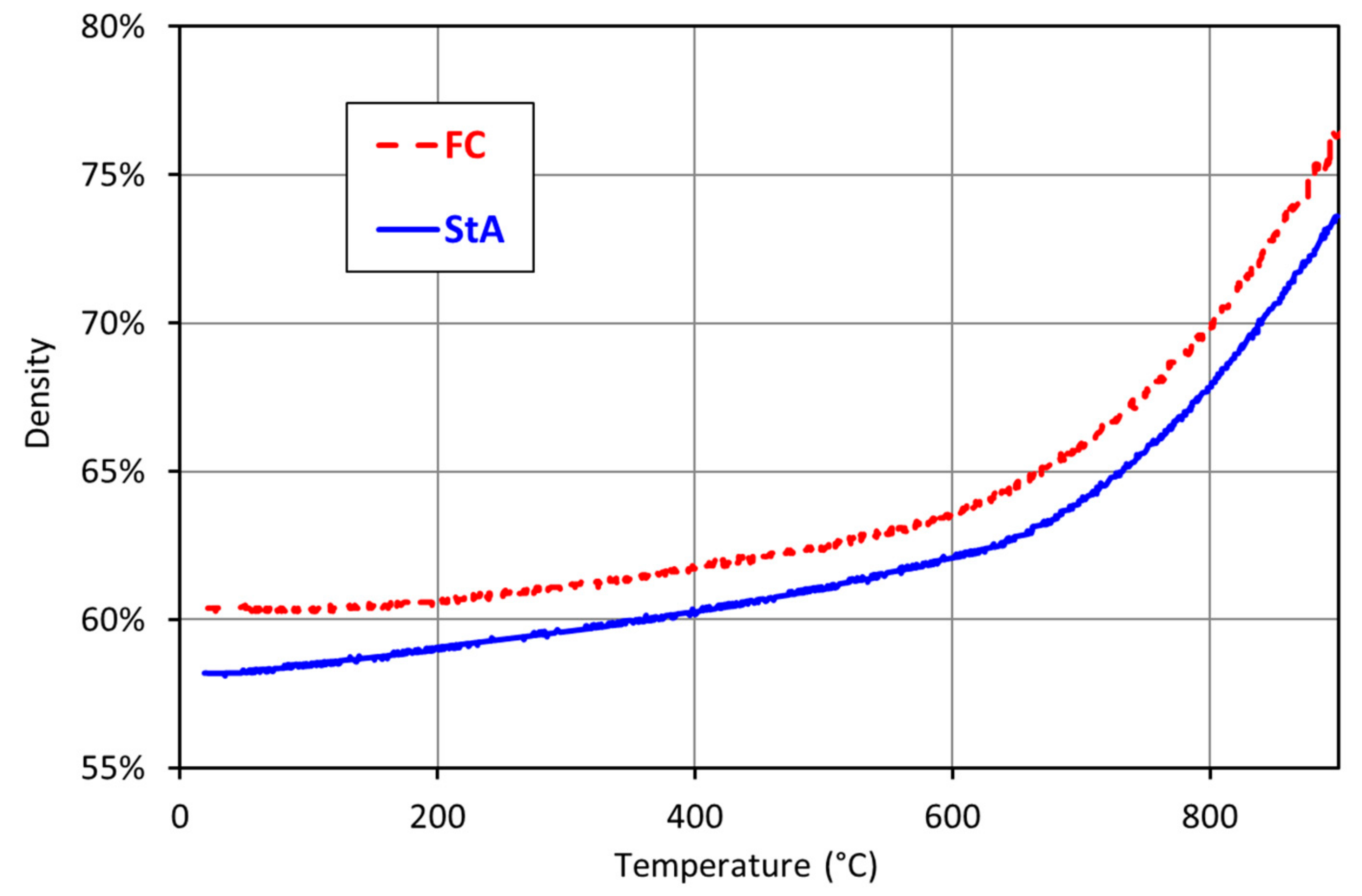
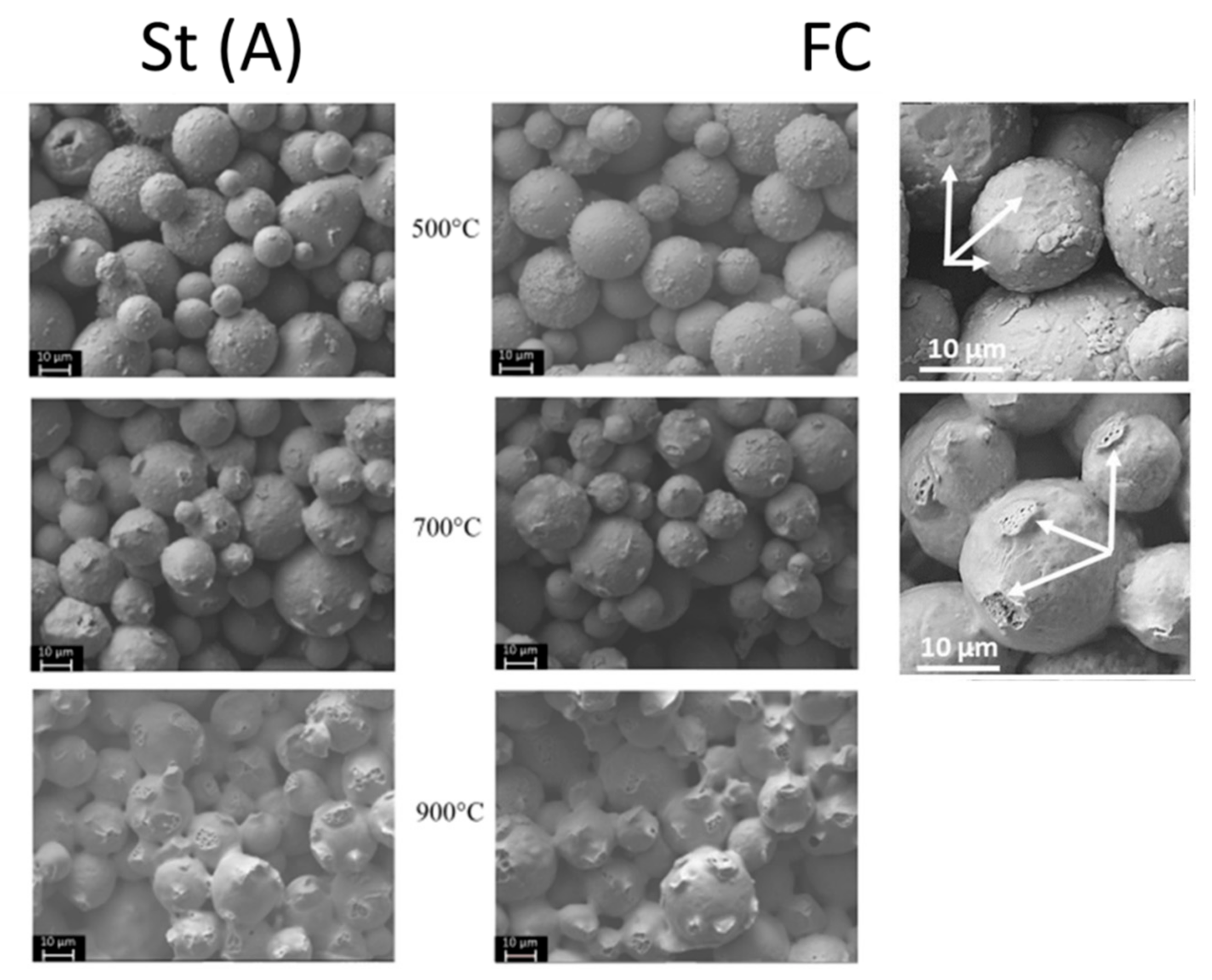
Figure 4 compares the densification curves obtained in the graphite die (StA) and alumina die (FC) configurations. Some experiments were interrupted at intermediate stages during heating, in order to observe the microstructure evolution on fractured samples (Figure 5).
The densification curves are parallel, with a significant slope from low temperatures which appears to be a “signature” of heating control by the thermocouple in position A. An acceleration can be observed at around 650 °C in both cases.
The final density (Table 1) was higher after sintering in an alumina die. However, we note that the initial density was also higher after compaction in this die. Consequently, there was no significant effect of the FC configuration with respect to the standard configuration. L. Minier [25] observed a larger discrepancy between the densities of nickel samples sintered in alumina and graphite dies, with densities of 94.5 and 90.4%, respectively. However, nickel is four times less conductive than copper and, unfortunately, the initial densities were not estimated, and the temperature regulation location was different.
SEM observations did not reveal any differences between the two configurations. The fractographs at 500 °C showed that there were no (or very few) dimples on the particle surface. Their absence indicates that neck formation and diffusion bonding has not yet taken place. Flattened areas at the contacts were observed (indicated by white arrows in the enlarged picture in Figure 5). The fractography at 700 °C show that small areas with dimples appeared, confirming the development of necks between particles. Some areas with dimples are indicated by white arrows in the enlarged picture in Figure 5. At 900 °C, the areas with dimples have increased in size, due to neck growth.

3.3. Comparison of Standard SPS (StB) and No Current (NC) Conditions

Figure 6 compares the densification curves obtained in graphite dies in the configurations with alumina platelets (NC) and without (StB). The fractured samples were observed and showed the same characteristics as those in Section 3.2., i.e., flattened contacts without bonding at 500 °C and diffusion bonding and increasing dimples above 700 °C. They are not reported here.
Almost no densification was observed below 400 °C. The densification curves diverge above 600 °C, leading to a lower density for the NC configuration.
To enhance the difference between the two configurations, the pressure was increased in order to favor the contact areas at low temperature and, consequently, the current flow through the sample.
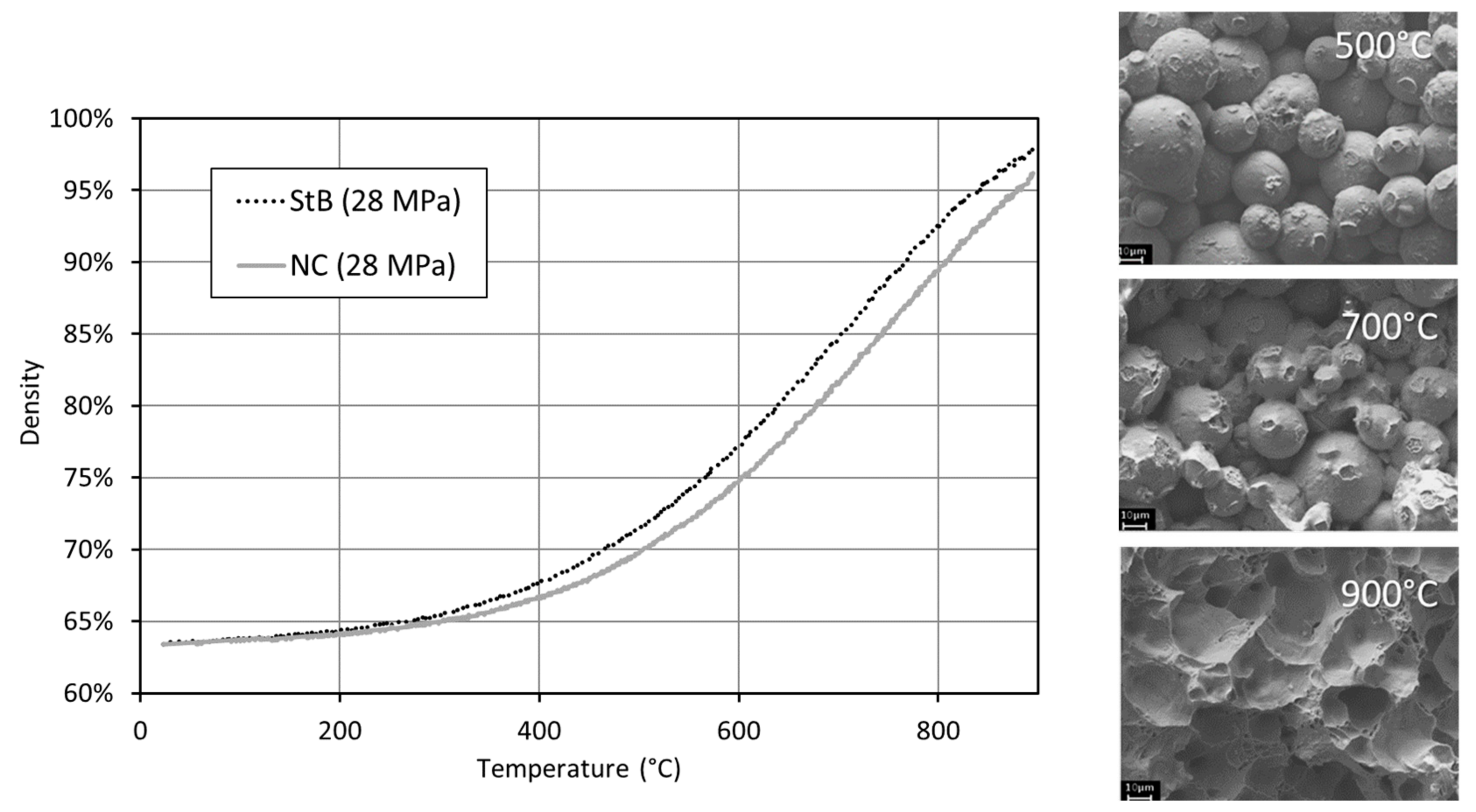
The densification curves under a pressure of 28 MPa, as well as the fractography at different temperatures, are shown in Figure 7.
As expected, under 28 MPa pressure, densification began earlier than under 4 MPa, with the higher pressure leading to an increased plastic deformation. The St and NC curves diverge earlier (from 300 °C). The highest final densification still occurred in the standard configuration.
Both samples were almost dense at 900 °C, but the final density was slightly higher in the standard configuration (97.3 ± 0.5%) than in the no current configuration (96.0 ± 0.2%). At 28 MPa, the necks formed earlier compared to the experiments at 4 MPa, but there is no visible microstructural difference between NC and St configurations; hence, only the fractographs of the sample obtained for NC are presented Figure 7.

4. Discussion

No significant difference could be observed between FC and St configurations, but a small systematic difference between St and NC configurations was observed. Differences linked to the position of the thermocouples were also noted, i.e., faster densification before 600 °C for the thermocouple in position A (located in the punch).
Furthermore, some evaluations of heating by simulation were performed, using electrical conductivity data measured in our materials.

4.1. Electrical Conductivity throughout the SPS Process

The electrical conductivity of a sample depends on its purity, density and temperature, but also on its thermal history. Compressibility tests, performed in an 8 mm tungsten die, showed that the relative densities of copper compacts varied between 55.5% when compacted under 2 MPa to 60% under 20 MPa. Even in the case of the 60% dense compacts, the electrical conductivity was too low to be measured with the SIGMATEST® 2.069 probe (<0.5 MS·m−1). The diffusion bonds between particles were not yet formed and the native oxide layer on the copper particles acted as conductivity barrier, so that high electrical contact resistance existed between the particles. For this reason, the correlation between electrical conductivity and density was investigated via electrical conductivity measurements at room temperature on samples sintered at different temperatures in the SPS device (Figure 8), in order to estimate the conductivity of samples during the sintering process after the very first step, where grain-to-grain contacts are formed.
The linear regression shows that the effective electrical conductivity at room temperature (σ) can be expressed as a function of the sample relative density d:
σ T 0 = 1.33 × 10 8 × d 0.55 ,
This simple linear relationship, which is similar to the well-known Bruggeman effective medium formula [26] with a realistic percolation threshold of 55% instead of 1/3, is in better agreement with experimental results than previous experimentally based relations such as that of Argento [27]:
σ * = σ d d 0 1 d 0 3 2 1 d 0 ,
The effective conductivity becomes zero when the density is 55%, which roughly corresponds to the natural packing density of the powder, and it reaches 60 × 106 S/m for dense copper, which is a classic typical value for Cu. It must be kept in mind that (2) was obtained for sintered samples, while cold-compacted samples exhibited very low conductivity even at 60% density. Note that from 58% density, the partially sintered samples had a conductivity of the order of 5 × 10⁶ S/m, while that of graphite is of the order of 6.3 × 10⁴ S/m, i.e., 70 to 80 times lower.
During sintering, the electrical conductivity of the sample (σT) also varies with temperature T, due to the intrinsic temperature dependency of bulk conductivity:
σ T = σ T 0 1 1 + α T T 0
where σT0 is the electrical conductivity at room temperature (calculated using (2)) and α is the temperature coefficient of resistivity (α = 0.00393 °C−1 in copper [28]).
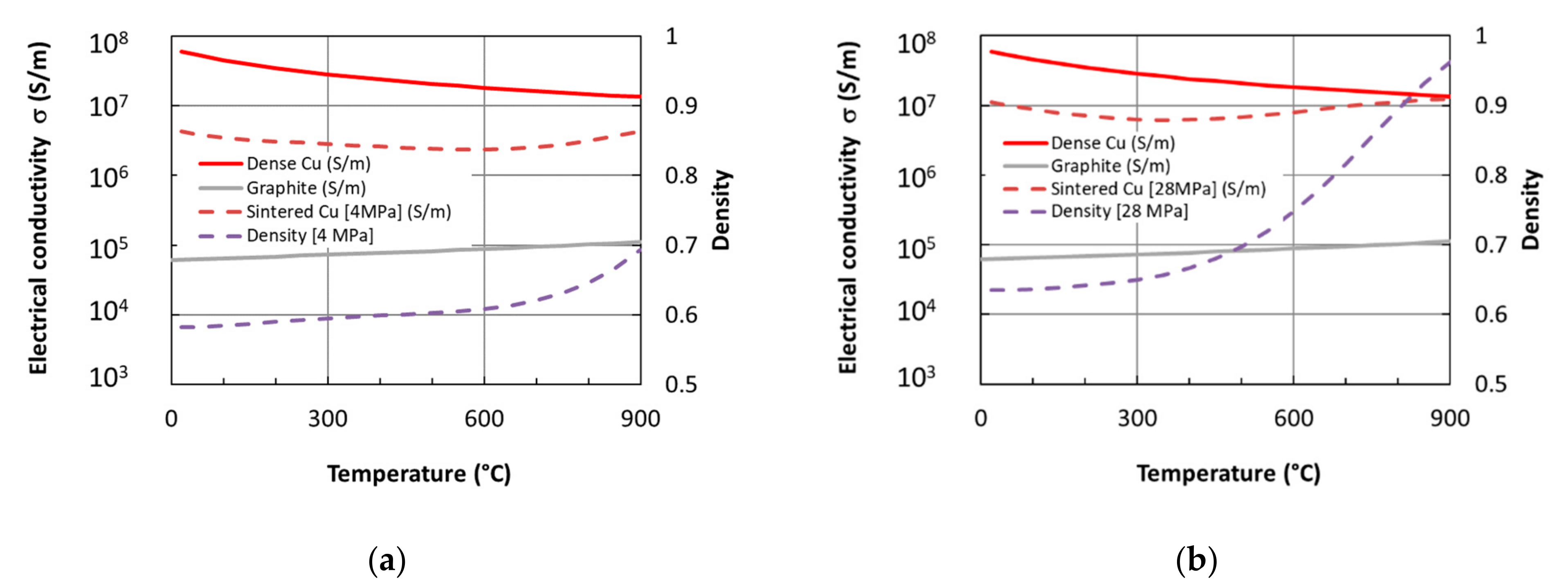
The evolution of the effective electrical conductivity of the sample (σT) throughout a typical SPS experiment at constant heating rate is shown in Figure 9. The density was calculated from the punch displacement, continuously recorded during the SPS cycle. It evolved from 58 to 72% between room temperature (T0 = 20 °C) and 900 °C at 4 MPa. The sample conductivity was deduced from (2) and (4). The electrical conductivity of the graphite die is plotted for comparison. It was calculated from (3) with σ = 62,500 S·m−1 at room temperature (Mersen data) and α = −0.0005 °C−1 [28].
The shape of the conductivity curve, with a minimum value (for sintered Cu), results from two opposite and competitive effects when the temperature is increased: the increase in particle contacts due to sintering (2) and the decrease in the bulk conductivity (4):
-
From room temperature to around 450 °C, the sample conductivity decreases because the bulk conductivity decrease overrides the slow sintering processes. This estimation assumes that good conductivity contacts are formed, which is required for applying (2). At the very beginning of the SPS process, the powder conductivity is much lower, due to the abovementioned point;
-
Above 450 °C, the strong densification while the temperature is increasing leads to an increase in the effective electrical conductivity.
As soon as good conductive contacts between particles were formed, the effective conductivity of the copper sample became more than 25 times higher than that of the graphite tool. As the diameter ratio between the sample and the die was 3 (90 and 30 mm, respectively) i.e., the surface ratio was 8, the specific resistance of the powder sample opposing the current flow was typically 1/3 of that of the die, so that a significant total current was flowing in the powder and in the die.

4.2. FEM Simulations of the Different Configurations

FEM simulations were used to compare the characteristic behaviors of the St, FC and NC configurations, using simplified conditions representative of experiments. In each case, a predefined voltage was applied, with a value adapted to ensure a roughly constant sample heating rate close to 50 °C/min. The thermal boundary conditions were: (i) the thermally insulated ends of the (long) punches and (ii) the radiative loss to the environment from the other outer surfaces (emissivity set to 1). These oversimplified conditions were not intended to simulate complex actual experiments, but to provide general tendencies. Calculations were performed in 2D axisymmetric conditions, using COMSOL Multiphysics software.
Figure 10 shows the maps of current density together with current lines, the dissipated Joule power and the temperature when the sample temperature is around 700 °C (600 s). Table 2 shows, for the three configurations, the fraction of the current which passes through the sample and the comparison of the production of heat by the Joule effect in the sample with the heat flows exchanged by conduction, for the punches and the die, respectively.
A high fraction of the current passes through the sample in the standard configuration (30%) and, of course, in the FC configuration (100%). A small part of the current passes through the edges of the sample even in the NC configuration, due to the very high conductivity of the powder compared to that of graphite, but it remains very small (1%).
Power dissipation (density of heat production) is highest at the punches and negligible in the sample in all cases (log representation in the figure). The local contribution of the Joule effect in the sample is, in any case, negligible for these copper samples.
In all cases, the punches-to-sample heat flow is considerably larger than the Joule power inside sample. Consequently, the sample is mainly heated by the punches.
The sample is cooled (negative flow) by the die, which is itself cooled by the external exchanges, as this flow is very large compared to the production of heat in the sample.

4.3. Simulations vs. Experimental Results

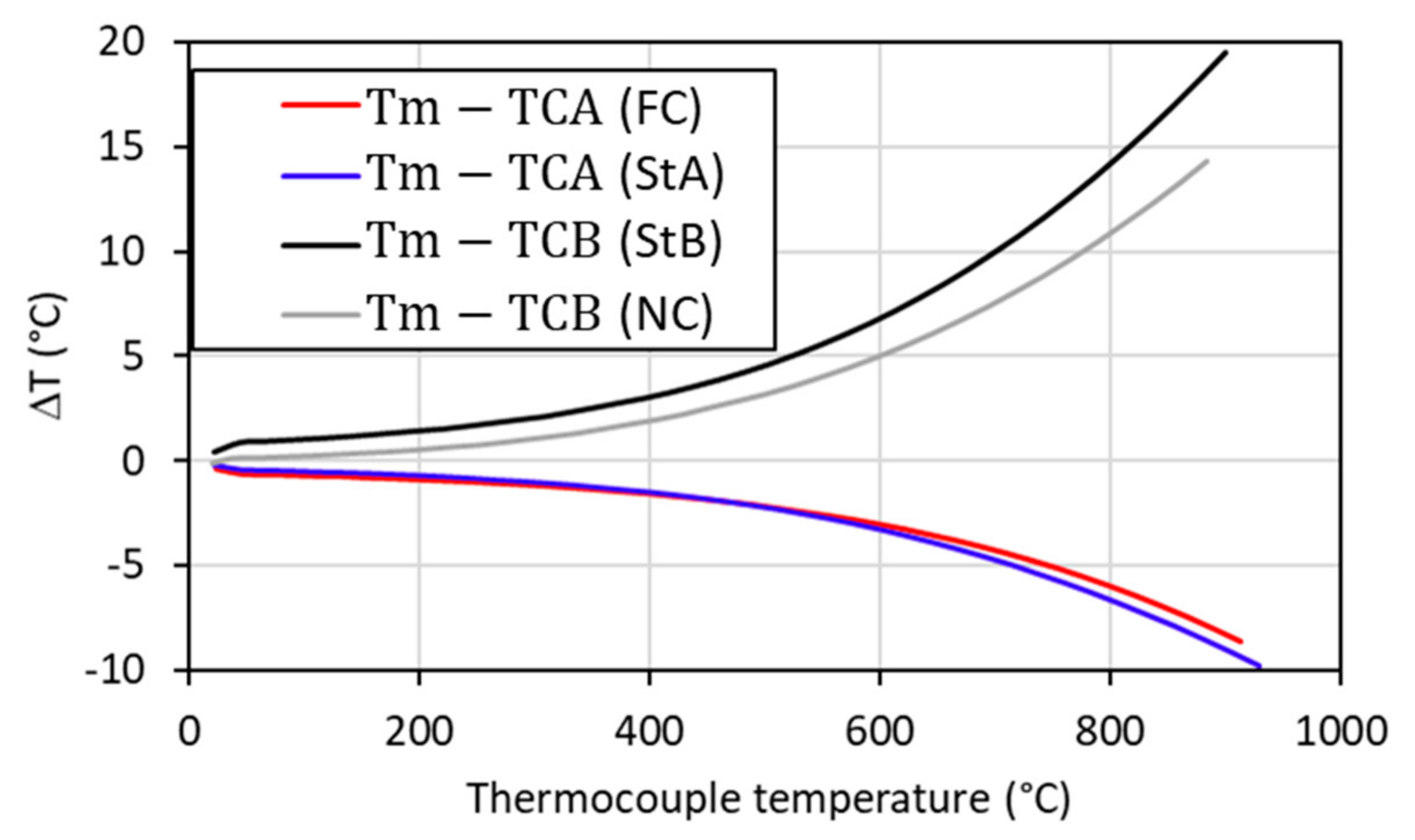
Figure 11 shows the calculated evolution of the temperature deviations between the thermocouple positions and the mean temperature of the samples. The sample was colder than the thermocouple in position A (located in the punch, considered as a heating source) and hotter than the thermocouple in position B (located in the die, considered as a cooling source). The simulations did not support these experimental results well. Indeed, the densification was greater and occurred earlier when the thermocouple was in position A. This suggested an underestimation of the sample temperature regarding location B.
There was no significant temperature difference between the configurations for the same thermocouple location (FC and STA on the one hand, NC and STB on the other hand). The experimental observation that only the absence of current (NC) led to a significant decrease in densification can therefore not be linked to a thermal cause. This suggests that the flow of a current in the sample modifies the densification mechanisms in this copper powder, for the given conditions. This effect appears to be a “threshold” effect because switching to 100% of the current (FC configuration) did not produce an effect significantly different from 30% of the current (St configuration). No modification of the microstructure by the flow of current could be observed to indicate the nature of this effect.

5. Conclusions

The densification curves of a pure copper powder were analyzed for three different configurations and with different thermocouple positions, from the relative electrical conductivities of the sample and the tool, from FEM simulations and from SEM observations of fracture surfaces. Densification appeared to be sensitive to the position of the regulation thermocouple. This could be explained by different actual thermal cycles applied to the samples, due to thermal gradients inside the system. Only the absence of current in the specimen led to a decrease in densification. The effective conductivity of the copper sample was more than 25 times higher than that of the graphite tool. Therefore, copper specimens were scarcely heated by the tool. However, FEM simulations highlighted no significant temperature differences between the configurations, suggesting that this was not linked to a thermal cause but rather to a current effect. However, no modification of the microstructure by the flow of current could be observed.

Author Contributions

Conceptualization, S.L.G., J.-M.C. and F.B.; methodology, R.C.; validation, J.-M.C., S.L., S.L.G. and F.B.; formal analysis, R.C. and F.C.; investigation, R.C., S.L.G. and S.L.; resources, R.C., S.L. and F.C.; writing—original draft preparation, R.C. and S.L.G.; writing—review and editing, J.-M.C. and S.L.G.; supervision, J.-M.C. and F.B. All authors have read and agreed to the published version of the manuscript.

Funding

This work received a grant from the French National Agency (ANR) (ANR-11-BS09-020-02-MF2) as part of the project MF2.

Data Availability Statement

Data is contained within the article. A part of data presented in this study are available in [Collet. R Thèse de doctorat “Mécanismes de consolidation et de densification de poudres de cuivre lors d’un frittage par SPS”, Université de bourgogne, 30 novembre 2015].

Acknowledgments

The authors thank Frédéric Herbst (ICB, UMR 6303 CNRS) for his help with the SEM analyses.

Conflicts of Interest

The authors declare no conflict of interest.

References

  1. Tokita, M. Trends in advance SPS Spark Plasma Sintering systems and technology. J. Soc. Powder Technol. Jpn. 1993, 30, 790–804. [Google Scholar] [CrossRef] [Green Version]
  2. Song, X.; Liu, X.; Zhang, J. Neck Formation and Self-Adjusting Mechanism of Neck Growth of Conducting Powders in Spark Plasma Sintering. J. Am. Ceram. Soc. 2006, 89, 494–500. [Google Scholar] [CrossRef]
  3. Diouf, S.; Fedrizzi, A.; Molinari, A. A fractographic and microstructural analysis of the neck regions of coarse copper particles consolidated by spark plasma sintering. Mater. Lett. 2013, 111, 17–19. [Google Scholar] [CrossRef]
  4. Zhang, Z.H.; Liu, Z.F.; Lu, J.F.; Shen, X.B.; Wang, F.C.; Wang, Y.D. The sintering mechanism in spark plasma sintering—Proof of the occurrence of spark discharge. Scripta Mater. 2014, 81, 56–59. [Google Scholar] [CrossRef]
  5. Aman, Y.; Garnier, V.; Djurado, E. Pressure-less spark plasma sintering effect on non-conventional necking process during the initial stage of sintering of copper and alumina. J. Mater. Sci. 2012, 47, 5766–5773. [Google Scholar] [CrossRef]
  6. Guyot, P.; Rat, V.; Coudert, J.F.; Jay, F.; Maître, A.; Pradeilles, N. Does the Branly effect occur in spark plasma sintering? J. Phys. D Appl. Phys. 2012, 45, 092001. Available online: https://iopscience.iop.org/article/10.1088/0022-3727/45/9/092001 (accessed on 1 November 2021). [CrossRef]
  7. Ratzker, B.; Sokol, M.; Kalabukhov, S.; Frage, N. Compression creep of copper under electric current studied by a spark plasma sintering (SPS) apparatus. Mater. Sci. Eng. A. 2018, 712, 424–429. [Google Scholar] [CrossRef]
  8. Collet, R.; Le Gallet, S.; Charlot, F.; Lay, S.; Chaix, J.M.; Bernard, F. Oxide reduction effects in SPS processing of Cu atomized powder containing oxide inclusions. Mater. Chem. Phys. 2016, 173, 498–507. [Google Scholar] [CrossRef]
  9. Hulbert, D.M.; Anders, A.; Andersson, J.; Lavernia, E.J.; Mukherjee, A.K. A discussion on the absence of plasma in spark plasma sintering. Scr. Mater. 2009, 60, 835–838. [Google Scholar] [CrossRef]
  10. Demuynck, M.; Erauw, J.P.; Van der Biest, O.; Delannay, F.; Cambier, F. Densification of alumina by SPS and HP: A comparative study. J. Eur. Ceram. Soc. 2012, 32, 1957–1964. [Google Scholar] [CrossRef]
  11. Medri, V.; Monteverde, F.; Balbo, A.; Bellosi, A. Comparison of ZrB2-ZrC-SiC Composites Fabricated by Spark Plasma Sintering and Hot-Pressing. Adv. Eng. Mater. 2005, 7, 159–163. [Google Scholar] [CrossRef]
  12. Bernard-Granger, G.; Addad, A.; Fantozzi, G.; Bonnefont, G.; Guizard, C.; Vernat, D. Spark plasma sintering of a commercially available granulated zirconia powder: Comparison with hot-pressing. Acta Mater. 2010, 58, 3390–3399. [Google Scholar] [CrossRef]
  13. Lee, G.; Olevsky, E.A.; Maniere, C.; Maximenko, A.; Izhvanov, O.; Back, C.; McKittrick, J. Effect of electric current on densification behavior of conductive ceramic powders consolidated by spark plasma sintering. Acta Mater. 2018, 144, 524–533. [Google Scholar] [CrossRef]
  14. Balbo, A.; Sciti, D. Spark plasma sintering and hot pressing of ZrB2–MoSi2 ultra-high-temperature ceramics. Mater. Sci. Eng. A. 2008, 475, 108–112. [Google Scholar] [CrossRef]
  15. Langer, J.; Hoffmann, M.J.; Guillon, O. Direct comparison between hot pressing and electric field-assisted sintering of submicron alumina. Acta Mater. 2009, 57, 5454–5465. [Google Scholar] [CrossRef]
  16. Trzaska, Z.; Bonnefont, G.; Fantozzi, G.; Monchoux, J.P. Comparison of densification kinetics of a TiAl powder by spark plasma sintering and hot pressing. Acta Mater. 2017, 135, 1–13. [Google Scholar] [CrossRef] [Green Version]
  17. Collet, R.; Le Gallet, S.; Lay, S.; Charlot, F.; Bonnefont, G.; Fantozzi, G.; Chaix, J.M.; Bernard, F. SPS Mechanisms in Spherical Copper Powders. In Proceedings of the Congress Proceedings from World PM2016 Congress & Exhibition, Hamburg, Germany, 9–13 October 2016. [Google Scholar]
  18. Saunders, T.; Grasso, S.; Reece, M.J. Plasma formation during electric discharge (50 V) through conductive powder compacts. J. Eur. Ceram. Soc. 2015, 35, 871–877. [Google Scholar] [CrossRef]
  19. Chaim, R. Densification mechanisms in spark plasma sintering of nanocrystalline ceramics. Mater. Sci. Eng. A. 2007, 443, 25–32. [Google Scholar] [CrossRef]
  20. Munir, Z.A.; Anselmi-Tamburini, U.; Ohyanagi, M. The effect of electric field and pressure on the synthesis and consolidation of materials: A review of the spark plasma sintering method. J. Mater. Sci. 2006, 41, 763–777. [Google Scholar] [CrossRef]
  21. Collet, R.; Le Gallet, S.; Naimi, F.; Charlot, F.; Bonnefont, G.; Fantozzi, G.; Chaix, J.M.; Bernard, F. Effect of current on the sintering of pre-oxidized copper powders by SPS. J. Alloys Compd. 2017, 692, 478–484. [Google Scholar] [CrossRef]
  22. Collard, C.; Trzaska, Z.; Durand, L.; Chaix, J.M.; Monchoux, J.P. Theoretical and Experimental Investigations of Local Overheating at Particle Contacts in Spark Plasma Sintering. Powder Technol. 2017, 321, 458–470. [Google Scholar] [CrossRef]
  23. Anselmi-Tamburini, U.; Gennari, S.; Garay, J.E.; Munir, Z.A. Fundamental investigations on the spark plasma sintering/synthesis process: II. Modeling of current and temperature distributions. Mater. Sci. Eng. A 2005, 394, 139–148. [Google Scholar] [CrossRef]
  24. Trapp, J.; Kieback, B. Fundamental principles of spark plasma sintering of metals: Part I—Joule heating controlled by the evolution of powder resistivity and local current densities. Powder Metall. 2019, 62, 297–306. [Google Scholar] [CrossRef]
  25. Minier, L.; Le Gallet, S.; Grin, Y.; Bernard, F. Influence of the current flow on the SPS sintering of a Ni powder. J. Alloys Compd. 2010, 508, 412–418. [Google Scholar] [CrossRef]
  26. Bruggemann, D.A.G. Calculation of Effective Constitutive Parameters of Heterogeneous Substances, I, Permittivity and Conductivity for Dilute Composite Mediums of Isotropic Substances. Ann. Phys. 1935, 24, 636–679. [Google Scholar]
  27. Argento, C.; Bouvard, D. Modeling the effective thermal conductivity of random packing of spheres through densification. Lnt. J. Heat Mass Transfer. 1996, 39, 1343–1350. [Google Scholar] [CrossRef]
  28. Lide, D.R. CRC Handbook of Chemistry and Physics, 64th ed.; Lide, D.R., Ed.; CRC Press: Boca Raton, FL, USA, 2004. [Google Scholar]
Figure 1. (a) Morphology (SEM observation) and (b) microstructure (FIB-SEM cross section) of TEKMAT Cu-38 copper powder particles.
Jmmp 05 00119 g001
Figure 2. The configurations used to control the current flow. The two standard SPS configurations (St) with graphite die differ in the thermocouple position (A or B), in order to ensure relevant comparisons with the cases of forced current (FC, alumina matrix) or no current (NC, alumina platelets) through the sample.
Jmmp 05 00119 g002
Figure 3. Comparison of standard SPS configurations (St) with two different positions of the thermocouple used to control the thermal cycle (positions A and B in Figure 2).
Jmmp 05 00119 g003
Figure 4. Densification of the copper powder during sintering for standard SPS conditions (St) and forced current (FC) conditions, with applied pressure 4 MPa and heating rate 50 °C·min−1 (thermocouple in position A).
Jmmp 05 00119 g004
Figure 5. Fracture surfaces observed by SEM on samples after SPS processing in standard (StA) and forced current (FC) conditions, under 4 MPa at 50 °C·min−1 up to 500 °C, 700 °C and 900 °C.
Jmmp 05 00119 g005
Figure 6. Densification of the copper powder during sintering in the cases of no current (NC) and standard SPS (StB), with applied pressure 4 MPa, heating rate 50 °C·min−1 (thermocouple in position B).
Jmmp 05 00119 g006
Figure 7. Densification of the copper powder during sintering in the cases of no current (NC) and standard SPS (StB) when a pressure of 28 MPa is applied. Fracture surfaces observed by SEM in the sample obtained in standard conditions (StB) at 500, 700 and 900 °C.
Jmmp 05 00119 g007
Figure 8. Effective electrical conductivity at room temperature of Cu samples sintered by SPS at temperatures between 300 and 1000 °C.
Jmmp 05 00119 g008
Figure 9. Evolution of the relative density of a copper sample during SPS experiments at constant heating rate (dT/dt = 50 °C·min−1) and effective electrical conductivity of the copper sample calculated from the density and Equations (2) and (3), for two applied pressures: (a) p = 4 MPa and (b) p = 28 MPa. The conductivities of graphite and dense copper are plotted for comparison purposes.
Jmmp 05 00119 g009
Figure 10. FEM simulation of heating for the three configurations. Snapshots of current density (i), heat production rate (P) (logarithmic scale) and temperature (T) at t = 600 s (average T around 700 °C inside the specimen). The same temperature–color scale is used for the three configurations in each case.
Jmmp 05 00119 g010
Figure 11. FEM simulation of heating for the three configurations. Evolution of the difference between the mean sample temperature (Tm) and the temperature at the thermocouple position (A or B) during the simulated heating at about 50 °C·min−1.
Jmmp 05 00119 g011
Table 1. Experimental device characteristics and initial and final densities of sample heated up to 900 °C at constant heating rate (50 °C·min−1) under pressure P. The initial density (d0) was calculated from the measured shrinkage at 900 °C, the measured final density (df) and the sample height (Lf).
ConfigurationThermocouple
Location
Pressure
P (MPa)
Final Height
Lf (mm)
Initial Density
d0 (%)
Final Density
df (%)
Shrinkage ΔL/L0
(%)
  • ▪ FC (Alumina die)
Punch (A)44.8360.676.420.7
  • ▪ St (Graphite die)
Punch (A)44.9058.273.620.8
  • ▪ St (Graphite die)
Die (B)43.6258.572.619.4
  • ▪ NC (Graphite die + alumina platelets)
Die (B)43.9058.769.816
  • ▪ St (Graphite die)
Die (B)283.4063.197.335.1
  • ▪ NC (Graphite die + alumina platelets)
Die (B)283.4463.49634
Table 2. Calculated values of ratios of current and heat exchanges to Joule heating inside the specimen for the different configurations at t = 600 s (average T around 700 °C inside the specimen). These ratios do not strongly evolve with time during heating.
ConfigurationStandard SPS
(St)
Jmmp 05 00119 i001
Forced Current (FC)
Jmmp 05 00119 i002
No Current
(NC)
Jmmp 05 00119 i003
Current   through   sample Total   current   intensity 28%100%1%
Punches   to   sample   heat   flow   Joule   power   inside   sample 4101301250
Die   to   sample   heat   flow   Joule   power   inside   sample −360−110−1000
Publisher’s Note: MDPI stays neutral with regard to jurisdictional claims in published maps and institutional affiliations.