Abstract
Wire Arc Additive Manufacturing (WAAM) with eccentric wire feed requires defined operating conditions due to the possibility of varying shapes of the deposited and solidified material depending on the welding torch orientation. In consequence, the produced component can contain significant errors because single bead geometrical errors are cumulatively added to the next layer during a building process. In order to minimise such inaccuracies caused by torch manipulation, this article illustrates the concept and testing of object-manipulated WAAM by incorporating robotic and welding technologies. As the first step towards this target, robotic hardware and software interfaces were developed to control the robot. Alongside, a fixture for holding the substrate plate was designed and fabricated. After establishing the robotic setup, in order to complete the whole WAAM process setup, a Gas Metal Arc Welding (GMAW) process was built and integrated into the system. Later, an experimental plan was prepared to perform single and multilayer welding experiments as well as for different trajectories. According to this plan, several welding experiments were performed to decide the parametric working range for the further WAAM experiments. In the end, the results of the first multilayer depositions over intricate trajectories are shown. Further performance and quality optimization strategies are also discussed at the end of this article.
1. Introduction
Due to the promising performance capabilities of WAAM, it has increased interest from not only universities but also industries to improve the process for safe industrial high performance metal additive manufacturing [1,2]. WAAM is classified in the technological category, directed energy deposition (DED), specifically, metal additive manufacturing. DED means that the raw material is supplied in the region of energy and deposited layer by layer in order to build up the desired component. Basically, in WAAM the initial material feed is supplied as wire, and the heat source is established in the form of an electric arc. This technology has shown many advantages such as a higher buy-to-fly ratio compared to conventional manufacturing processes, high material utilization, easy realtime repair, and lower cost compared to beam and powder based DED processes [3]. Likewise, to satisfy different process requirements, the melting of wire can also be performed by different arc welding processes such as Gas Metal Arc Welding (GMAW), Gas Tungsten Arc Welding (GTAW), or Plasma Arc Welding (PAW) [4]. Arc welding processes are then integrated into kinematic systems, such as an industrial robot or a CNC-linear movement to mechanize the process [5]. Therefore, according to Ding et al. [6,7], the quality of the deposition is considerably linked to the tool path strategy used.
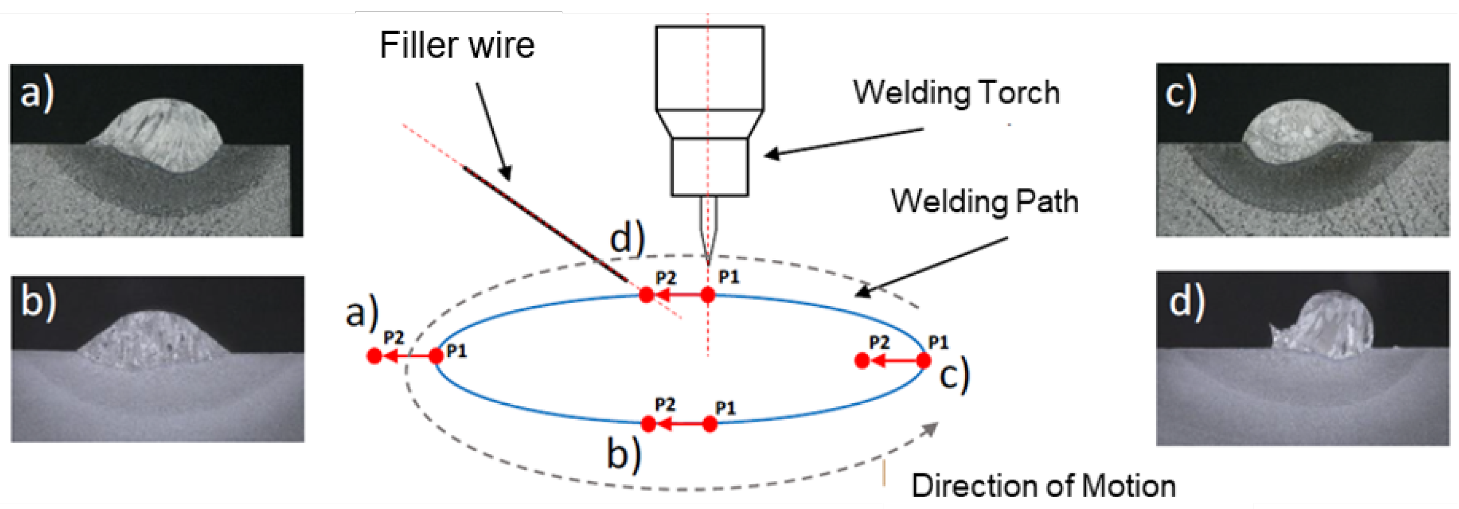
Generally, material is deposited through moving a torch in a layer-by-layer manner. It is frequently experimented by five axis tool-path generation in order to use flexible deposition strategies [8,9]. However, when raw wire material is fed eccentrically to the welding arc, as is the case for PAW- and TIG-based WAAM, cross-sectional geometrical inconsistencies are found in a single circular path as shown in Figure 1. Due to such direction-dependent geometrical errors, the accuracy of any built component is noticeably reduced, as it is further cumulatively added in the next layer. In addition, collision risks are associated with eccentric wire feeding, since the attachment of the wire feeder to the moving and rotating torch can be twisted. By taking the abovementioned issues into consideration, in this research, pure object manipulation [10] is implemented for layer-by-layer deposition with multi degrees of freedom of movement.
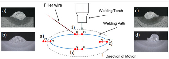
Figure 1.
Preliminary tests carried out at the Welding and Joining Institute of RWTH Aachen University to demonstrate direction-dependent weld bead formation with a moving welding torch with eccentric filler wire feeding. Figure (a,c) show asymmetric weld seam cross sectional geometry. Figure (b) shows an optimal desired geometry using forward feed of the filler wire, whereas figure (d) indicates again a geometrical error caused by the backward feed of the filler wire. The red-coloured vector has two point: (P1) is the arc root and (P2) indicates the the filler wire point from where it is supplied into the arc.
Robotic Planning: Pure Object Manipulation
The term object manipulation will be used in this work to establish a sharper distinction from related multidirectional manufacturing processes. Object manipulation describes the additive buildup of a component by exclusively manipulating the component/object along a welding head. The welding head is fixed in the workspace of the robot. Pure object manipulation is already given when the design of a classical 3D printer exclusively provides for the movement of the print bed. This makes it clear that in the context of this work, we must always speak of multidirectional additive manufacturing by means of object manipulation (OM-MDAM). The advantage of pure object manipulation is the exclusive manufacturing in the vertical position due to the fixed print head. As discussed, for the WAAM process with eccentric wire feeding (or alternatively sensor technology), when manipulating a weld head along a path, the entire weld head periphery would always have to be rotated around the entire weld head. Complex paths cannot be executed as a result. For this application, pure OM is advantageous. For a pure OM holding the weld head including the periphery, the print component will perform large rotational movements [10].
2. Related Work
WAAM is mainly performed by a robotic arc welding setup. While building a component one upon another layer, robotic path planning plays an important role in order to maintain dimensional accuracy of the component [11]. Robotic path planning has been carried out for different aspects in additive manufacturing such as the amount of deposition, difficult trajectories, infilling strategies, type of material, and size and structure of the component to be built [12]. In case of varying wall-thickness, Ma et al. have used a weaving torch movement to obtain a required weld bead width up to 16 mm of the weld seam [13]. The resulting adaptive paths were able to fill thin-walled structures with varying thickness.
Similarly, Ding et al. [6] have also proposed a tool-path generation strategy with the help of an algorithm that automatically generates optimal tool-paths for WAAM processes for a large class of geometries. To minimize multiple starting and stopping points in path planning, this algorithm first decomposes 2D geometries in a set of convex polygons based on a divide-and-conquer strategy. Thereafter, for every convex polygon, an unbroken tool-path is generated combining zigzag and contour printing strategies. In addition to single bead deposition, a multi-bead deposition tool path was also researched by Nguyen et al. [14] in order to keep the building rate constant through each layer. Mathematical models were developed to reduce valleys between adjacent seams considering overlapping volumes. As an approach, parabolic equations were formed on different sizes of the weld seam cross-sections using different welding parameters. Taking these equations, a mathematical model was created by overlapping parabolas in order to produce multi-bead profiles. Tool-path algorithms were not only developed and optimized in one plane (x,y) but also researched and optimized in the vertical plane (z-axis). One example of Reisgen et al. [15] can be stated here for the study on workpiece and welding torch height control in polydirectional WAAM applications that was applied to different materials. In this research, the current wire stickout length was acquired by means of image processing and combined with the actual position of the welding torch to compute a workpiece elevation map.
Path planning algorithms are more difficult when difficult trajectories are planned to be performed for WAAM. In such cases, multidirectional paths are also programmed to deposit material on the correct path with the desired deposition rate. One of the difficult geometries can be overhanging slices. Yuan et al. [16] proposed multidirectional WAAM slicing strategies for overhanging layers using robotic GMA welding. To build a horizontal wall as a bridge in between two vertical wall, they used different torch angles during the process. The torch angle was 0° for the first layer and it was gradually increased upto 90° for the last layer. Multidirectional WAAM processes can significantly reduce time and cost, if compared with conventional WAAM processes in which material is deposited from one direction. Undoubtedly, welding parameters must also be selected for different directions to hold uniform geometry of weld seams.
The path planning algorithms related to this work were introduced by Schmitz et al. [10]. For complex slices, the polygon is approximated, expanded, and then decomposed into multiple convex polygons for simplified planning. These polygons can be filled with different infill strategies and different major orientations. To generate a connected path from the decomposition that is executable and optimized under welding and robotic requirements, a clustered hamilton path (CHP) is searched in a graph generated specifically for this use case [10]. The result of this calculation is mostly a very edged path, which cannot be executed by the robot due to the multidirectional properties of the process presented in this work [10].
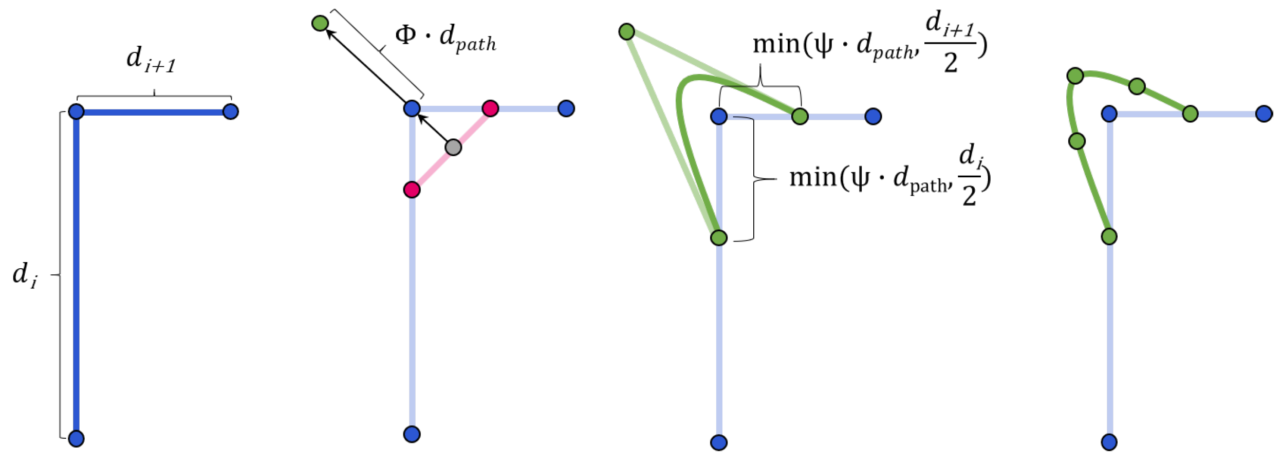
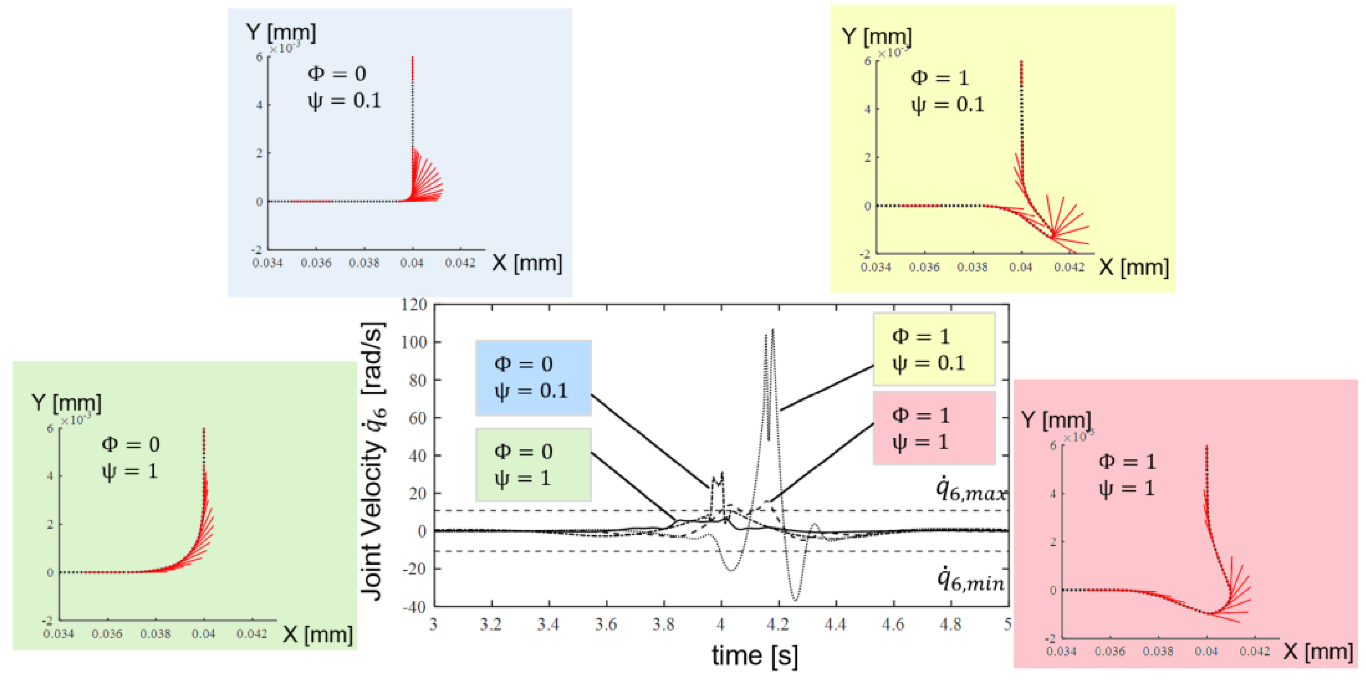
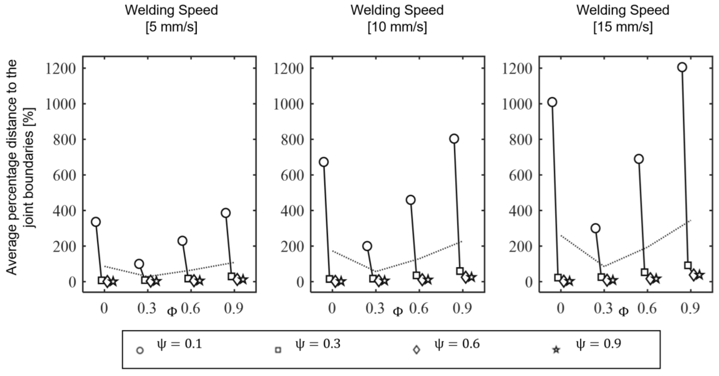
For this reason, the concept of smoothing in combination with an additional stretching of the path in the corners was investigated. It is explained in Figure 2 diagrammatically. It was shown that, for a specific robot, there is an optimal compromise between executability by the robot and optimal coverage of the slice by the calculated path [10]. Figure 3 shows four different smoothing () and stretching () parameter sets and their effect on the 6th axis joint velocity of the Kuka KR6 while following the corner for a constant path velocity at 10 mm/s. High smoothing has a positive effect, but the executability always depends on the desired constant printing speed. If this speed is increased, even a suitable smoothing can no longer ensure complete execution of the trajectory by the robot. This was tested using Design of Experiments. The smoothing and stretching parameters and the path velocity were systematically changed. The distance to the joint velocity limits were investigated. Figure 4 shows the positive effect of the smoothing but also an increasing negative influence on path velocity. This motivates the developments of the trajectory planner within this work.
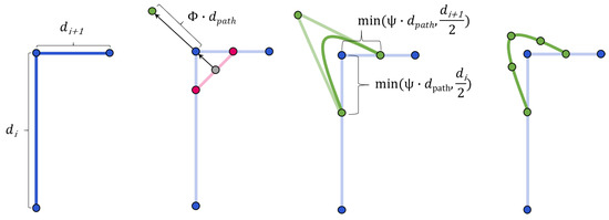
Figure 2.
Concept of smoothing and stretching of welding path presented by [10].
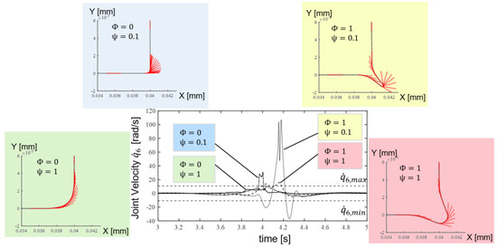
Figure 3.
Influence of different smoothing and stretching parameters on the robot joint values along the execution (here, the 6th joint of Kuka KR6).
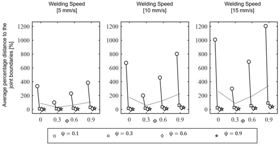
Figure 4.
Design of Experiment results of different smoothing parameters.
The terms path and trajectory are often used synonymously in the literature, although there is a difference. A path describes poses that can be represented in both joint angle space and cartesian space. These poses must be followed by the manipulator’s Tool Center Point (TCP) as it moves. Accordingly, a path is a purely geometric description of the motion. The trajectory is a path supplemented by a time law [17]. For example, it is reasonable for a WAAM process to specify a constant welding speed. Since a definition of the entire geometric path is too complex, a reduced number of parameters must be specified. Typically, these are extreme poses and intermediate poses. The definition of the motion-time law does not have to be determined at every point, but the total time of the trajectory as well as the limits of velocity and acceleration are still taken into account.
Furthermore, it is possible to assign a defined velocity or acceleration to poses. On this basis, a time sequence is generated that describes the position and orientation of the TCP of the robot over time depending on the constraints that apply. Since the movement of the manipulator takes place in joint space, a suitable inverse-kinematic algorithm is needed to transform the Cartesian poses into joint angles. Defining collision objects and path poses is easier in Cartesian space than in joint space. However, planning motions near singularities or with redundant degrees of freedom turns out to be difficult in Cartesian space. In such cases, it is easier to specify poses in joint angle space [17].
3. Materials and Methods
OM-WAAM mainly describes the fusion of two different technologies, i.e., robotics and arc welding. Importantly, both processes must be well synchronised and controlled so that the desired quality criteria can be fulfilled. Therefore, in this section, construction and preparation of robotic arm and welding system are introduced. Furthermore, the used trajectory optimization algorithm is introduced.
3.1. Robotic Hardware and Software Interface
The entire process preparation was programmed and implemented based on C++ and Python libraries. In the experimental setup, robots, welding head and sensors were integrated into the execution process. The Robot Operating System (ROS) provides a framework that allows all robots, sensors, manufacturing processes, databases and algorithms to communicate continuously. Furthermore, ROS provides direct access to visualization and user interfaces. This facilitates the handling of process execution and is used for research operations. To start a welding process, a component in STL file format has to be selected within the user interface. The file name is stored as a parameter on the central ROS parameter server (Figure 5). Thereupon, parameters can be set simultaneously, which become relevant on the level of the algorithms. Subsequently, the process preparation can be triggered. The handler coordinates the process and the transfer of the calculation results between slicer, manufacturing planning, path planning, and trajectory planning. The planning results are prepared for visualization and can be displayed in the Rviz Plugin component. Subsequently, the execution of a manufacturing process can be started. The execution control coordinates the collision-free movements between the print trajectories as well as the integration of the welding head during the welding trajectories. The control of the robot is implemented by the ROS moveGroup interface (Figure 5). The movement of the robot and the printing process can additionally be visualized in the Rviz Plugin Robot.
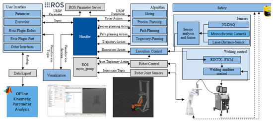
Figure 5.
Hardware Interface of the Multidirectional Additive Manufacturing.
The experimental setup for the OM-MDAM consisted of an industrial robot with 6 degrees of freedom, an end effector, and a welding head, which was mounted on an adjustable frame in a fixed position. A Kuka KR6 was used as the robot. With its balanced workspace and a maximum reach of 901.5 mm, the robot offers freedom in path and trajectory planning. The repeatability of ±0.03 mm provided the required accuracy for a precise manufacturing process. The maximum payload of 6 kg was sufficient for components printed from steel on a steel end effector. Figure 6 shows the test setup, during the execution of a multidirectional print test of the Fused Deposition Modelling process or welding process. The positioning in the working space of the robot of the print head was possible due to the three linear axes.

Figure 6.
Robotic setup constructed at the IGMR Institute.
3.2. End Effector
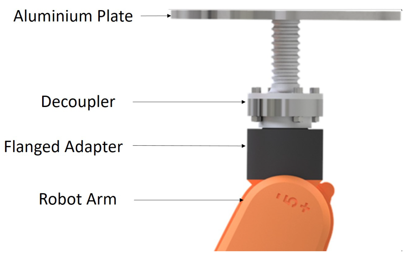
Special requirements are defined for an end effector that can be used for welding. The end effector must be sufficiently rigid to withstand any distortion stresses that may occur. A ground cable must be attached to the end effector, and the robot must be protected from electrical currents and heat. For this purpose, a 4-piece structure was chosen. Therefore, a particular end effector was constructed and can be seen in Figure 7 to fulfil the requirements. An aluminum plate was attached to the robot via an intermediate element, a decoupler, and the flange adapter. The aluminum plate was equipped with holes to establish a ground connection. In addition, the slotted holes were used to clamp a substrate plate to the aluminum plate. One challenge, especially for use on the KUKA KR6, was to minimize the weight. For this purpose, the aluminum plate was designed round and was provided with pockets to save material. The intermediate element was attached to the aluminum plate, which was essentially intended to build up distance to the flange of the robot and enable the use of decoupling. Additional notches were used to increase the surface area in order to dissipate additional heat. The decoupling was implemented from iglidur®X (plastic) or glass ceramic. The materials increased the electrical resistance and were temperature resistant in each case. Adjacent components were screwed exclusively to the decoupling.
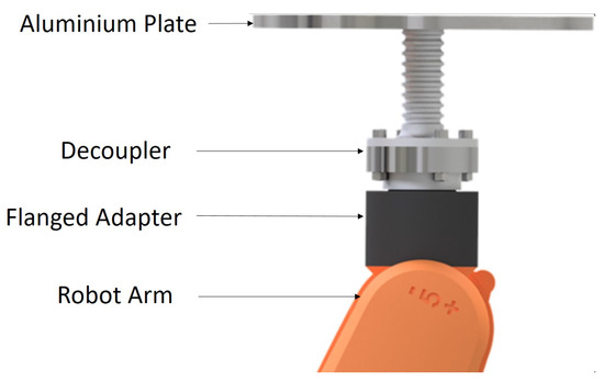
Figure 7.
End effector used in the context of this work.
3.3. Gas Metal Arc Welding (GMAW) for WAAM
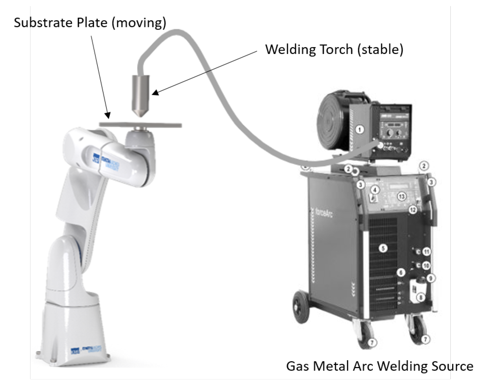
Welding is a process of joining of metals or plastics with the aid of heat, pressure, or both, with or without addition of filler material with a similar melting point. From a simulation perspective, WAAM is similar to multipass and multilayer welding processes. As discussed, several arc welding processes are suitable for application in WAAM. In particular, plasma welding is also used in order to fabricate components with high performance materials [18]. External wire-feeding in TIG welding gives the advantage of energy and material separation during the process, compared to GMAW. For first investigations of the kinematic setup with a real welding process, the collision risk of the endless wire electrode is associated with significantly lower costs than with the use of a tungsten electrode in TIG welding. By considering the anticipated process variant, a GMAW process setup was constructed and deployed in the robotic WAAM system. In Figure 8, the fundamental components of the WAAM process are described.

Figure 8.
GMAW based WAAM process with pure object manipulation.
3.4. Synchronisation of Both Robotic and Welding Process
The Phoenix 522 RC coldArc welding machine from EWM Hightech Welding GmbH was utilized. The MIG/MAG standard welding process was used under shielding gas EN ISO 14175-M21-ArC-18 (18% CO, 82% Argon) and EN ISO 14341-A G 3Si1 as wire electrode with a diameter of 1.2 mm. The material for the substrate plates was low-alloyed structural steel (S235JR) with 15 × 15 × 4 mm dimension. The welding process must also be controlled synchronously with the robot motion. Accordingly, a serial interface to an Arduino was integrated into the ROS environment for the welding device. The Arduino communicated directly with the 19-pin automation interface of the welding machine. This controlled the start and end of the process. Welding parameters (wire and welding speed, current/voltage, and pulse rate) were manually configured at the welding machine before starting the welding process. However, the implemented interface also allows continuous variation of welding parameters directly from the ROS system.
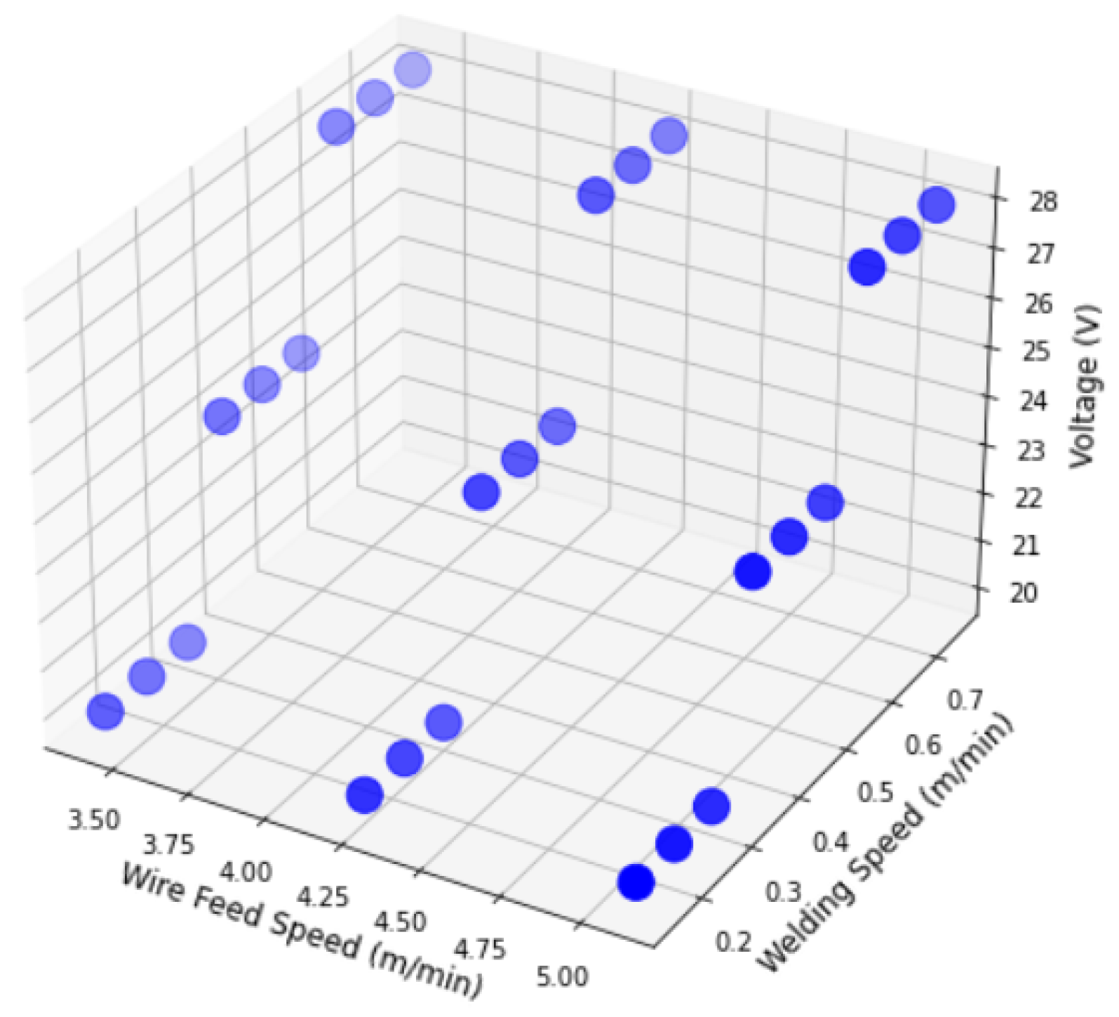
As a first step, the parametric boundary must be known for the WAAM process in order to perform further experiments within it. Therefore, a few pre-experiments were carried out by performing single layer depositions. Alongside, cross-sectional geometries such as height and width of the weld beads were also measured through the medium of metallographic imaging. In Figure 9, selected welding parameters for the pre-experiments and 27 experimental steps are displayed. Thereafter, if necessary, the parameter range can be shortened more by selecting a feasible weld bead geometry range. For instance, a geometry of weld beads with more than 4 mm width would bear the risk of the weld pool burning through the substrate plate. Therefore, the parameter-sets, which produce a bead geometry that is not desirable, can be avoided, and so the working range can be shortened. In case of a wall thickness of more than 4 mm, multipass path planning can be programmed, e.g., two parallel beads of the same width. After all, an interpolation algorithm will be developed to fill the experimental gaps and increase the parameter space of relation between weld parameters and geometry.
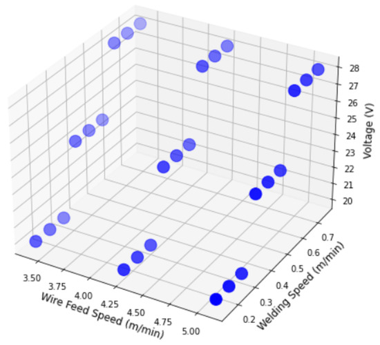
Figure 9.
GMA-Welding Parameter Range and Experimental plan.
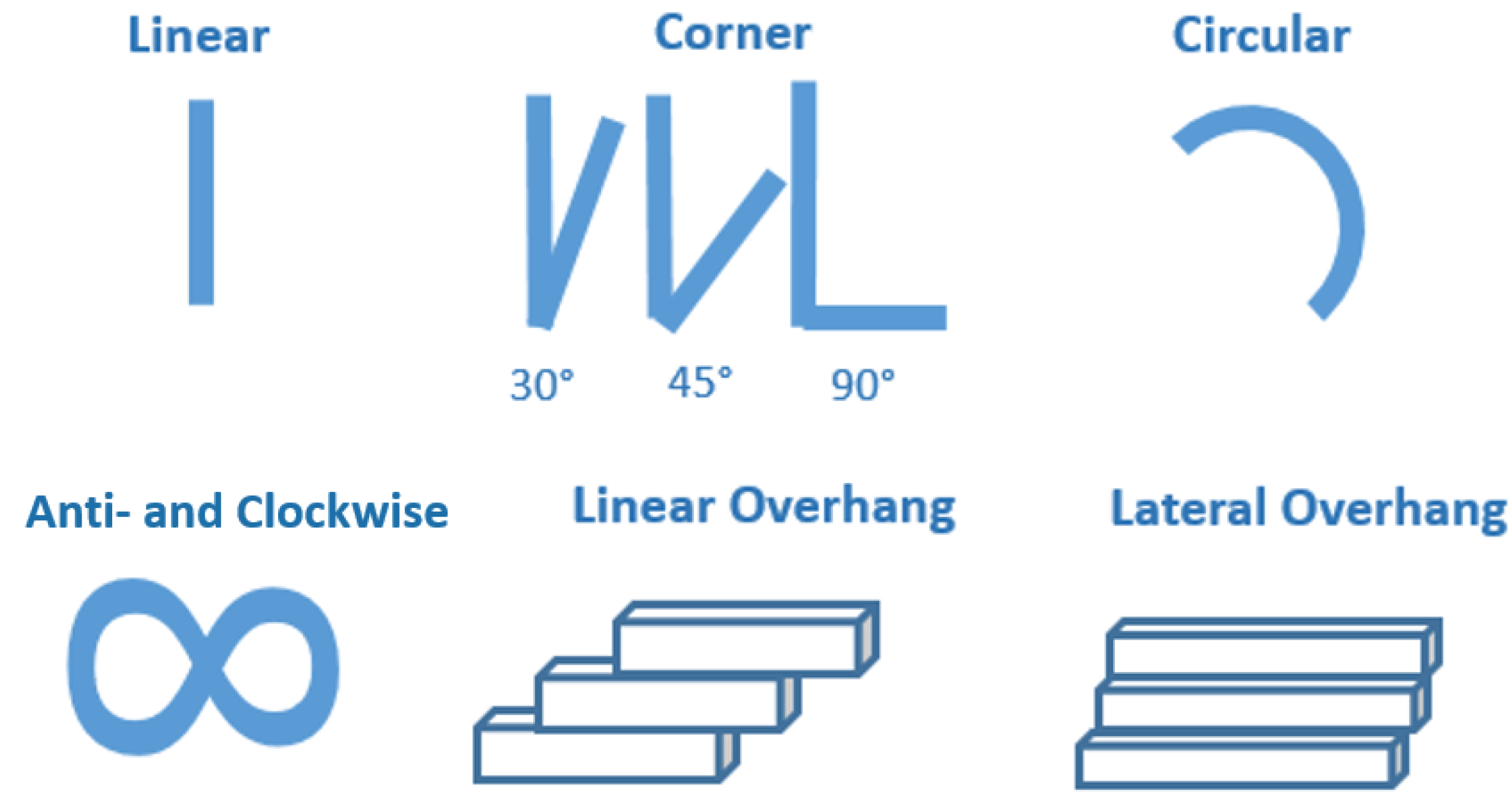
After experimenting with single layer welding with object manipulation, it was also essential to assess the ability of the whole synchronised system with additive material depositions. In addition, different trajectories were also tested in order to develop parameter optimisation strategies. As the KUKA robot was limited to actuate up to 6 kg and by considering the weight of the end effector fixture, substrate plate, and ground cable, 5 layers were decided to be manufactured within the experiments. In Figure 10, complex paths are shown with which the ability of the system could be tested for OM-MDAM. To work with them, parameters from single layer experiments were used.

Figure 10.
Experimental cases (paths) for OM-MDAM.
3.5. Trajectory Optimization
The requirements for a trajectory planner for OM-MDAM can be divided into five areas. Necessary criteria for the feasibility of the welding process are ensuring that the joint limits and joint velocity limits of the robot are respected. The characteristics of the planned paths and the associated large movements of the robot TCP (or the individual robot joint) within short time intervals impose high demands on compliance with joint limits, joint velocity limits, and joint acceleration limits. To meet component tolerances, planned path segments must be traversed continuously with minimal spatial deviation.
According to the robot limits and to minimize negative effects in the welding process, acceleration and jerk should be minimized. If the trajectory is executable, the ideal print result is predominantly in the foreground. Trajectory planning has a direct influence on this. Acceleration and jerk can also be minimized with respect to the reference system of the weld path in order to avoid negative effects on the liquid weld pool. Furthermore, the orientation of the welding head has a direct influence. The orientation of the path poses should be understood as both the direction of the wire feed and the angle of inclination of the weld head to the printing plane. The orientations can be functionally related to the path curvature by means of tests, for example. The path speed can also be linked and optimized with the path curvature and in combination with other welding parameters from a welding engineering point of view. These requirements can be met by varying different tools and influencing variables (optimization variables). If motions cannot be executed within joint velocity limits, the time periods between path support points can be stretched or compressed. While the overall duration of the process has little influence, a path speed that is as constant as possible in the object coordinate system must be maintained for a suitable print result. By specifically influencing the orientations, the welding result can be affected and, at the same time, positive influence can be exerted on compliance with joint limits and joint velocity limits. The same applies to changing the positions of the path support points. The initial trajectory solution, which is calculated before optimization, also has a major influence. This already defines areas in the joint angle space and thus configurations in which the robot will execute the process even after an optimization. A continuous course, without configuration changes and at a distance from the joint limits, can already be taken into account here. Starting from an initial trajectory solution, the optimization was performed. The initially calculated trajectory was used for the optimization by means of an Sequential Quadratic Programming algorithm and the library NLopt. References regarding the exact algorithm implemented can be found in [19,20]. For the optimization, a segmentation of the path into straight line and curve segments was used. The straight line segments were omitted, and only the curve segments were considered for the optimization. This step was justified on the basis of the larger joint movements. These can result in high speeds and accelerations and can lead to an execution stop if the kinematic limits of the industrial robot are exceeded. The curve segments were optimized with the following objective function:
The aim of the optimization is on the one hand to reduce the accelerations in the joint angles. Furthermore, the path or printing velocity should be as specified and constant. This is modeled by the deviation of an initial time span to the optimized time span . The execution of the trajectory should continue to follow the given path poses. The weighting, divided into individual positions or orientations, can be set separately. By means of a percentage influence factor , welding-specific correlations can also be included in the process. In the example shown, the influence of the path curvature on the path velocity was included. The influence factor allows the adjustment of the desired initial time spans depending on the path curvature . The solution space within which the objective function is optimized is defined by the optimization variables. For OM-MDAM, the time span is a way to influence path or printing velocity. Here, the time span was defined within a lower and upper bound:
Furthermore, deviations of position and orientation of path poses can be allowed. These are also constrained by maximum and minimum deviations: . To ensure feasibility by the robot, constraints were defined in the joint angle space as follows:
- Joint angle limits:
- Joint velocity limits:
- Joint acceleration limits:
At each iteration step, calculations in Cartesian space must be performed to evaluate the constraints and the objective function. This necessitates the regular transfer of the partial solutions from the joint angle space to the Cartesian space using a forward kinematic algorithm.
4. Results & Discussion
4.1. First Welding Results
As discussed in the previous section, single layer and multilayer experiments were carried out to acquire significant knowledge-based information such as the relationship between parameters and bead geometry, robotic maneuverability, and quality of deposition. In Figure 11, multi-layer weld beads are shown. The parameters used for the experiments in Figure 11 are give below in the Table 1. Single layer experiments were performed to record as well as to identify a possible working range according to the size of bead cross-section. From experiments with single layer linear depositions, it was found that the beads produced with higher voltage, such as in this case 28 V, have large width, i.e., more than 11 mm. This is not implementable as it introduces a large amount of heat into the substrate plate. This was how the working range was validated and shortened from the bead geometry perspective.
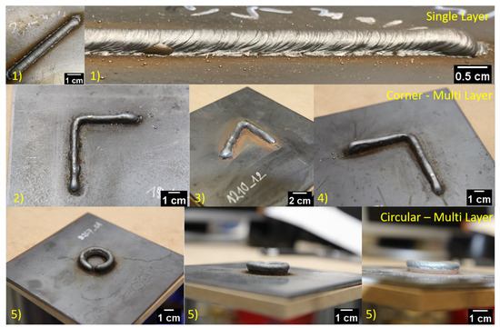
Figure 11.
Single- and Multiilayer trajectories built using WAAM With Pure Object Manipulation.

Table 1.
List of parameters used for the experiments in Figure 11.
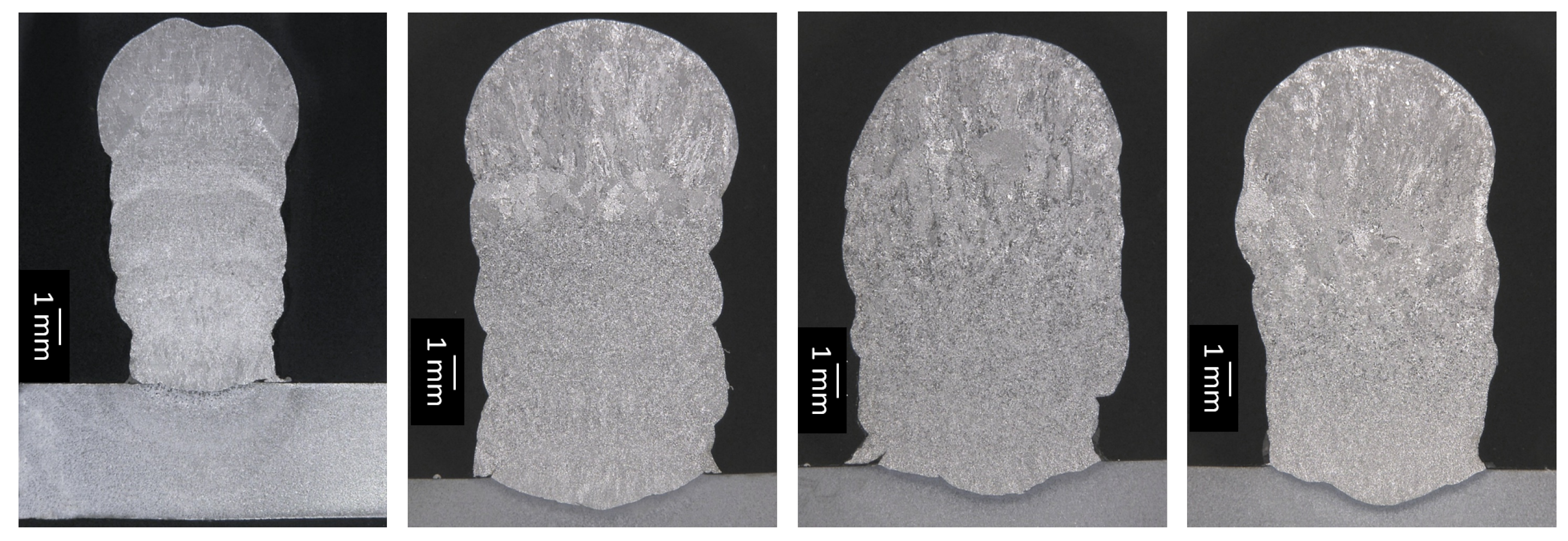
Performing visual inspection, it can be confirmed that the both the processes were synchronised to perform WAAM with 6D multidirectional object manipulation. Despite visual inspection, in order to estimate the quality of process, macrographic cross sections were analysed. In Figure 12, an asymmetric cross-section width was found because of the varying time interval between each layer. From these results, the robotic as well as welding parameters can be optimised to solve equivalent problems.
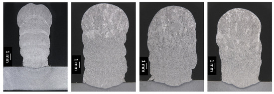
Figure 12.
Macrographic images to assess consistency of multilayer deposition.
4.2. Trajectory Optimization Results
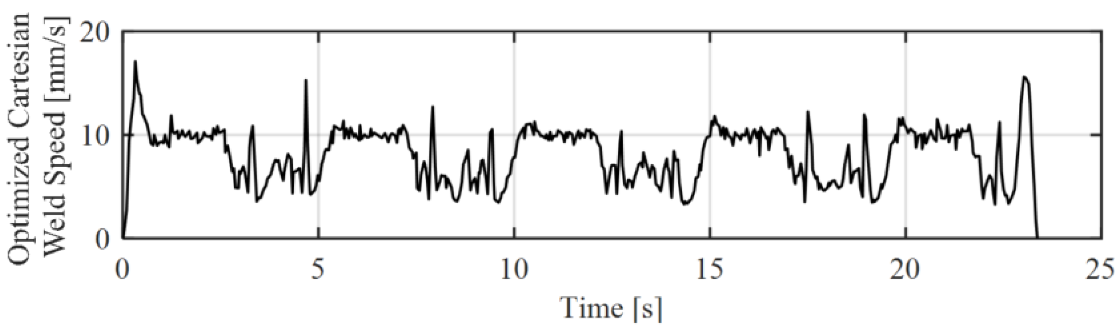
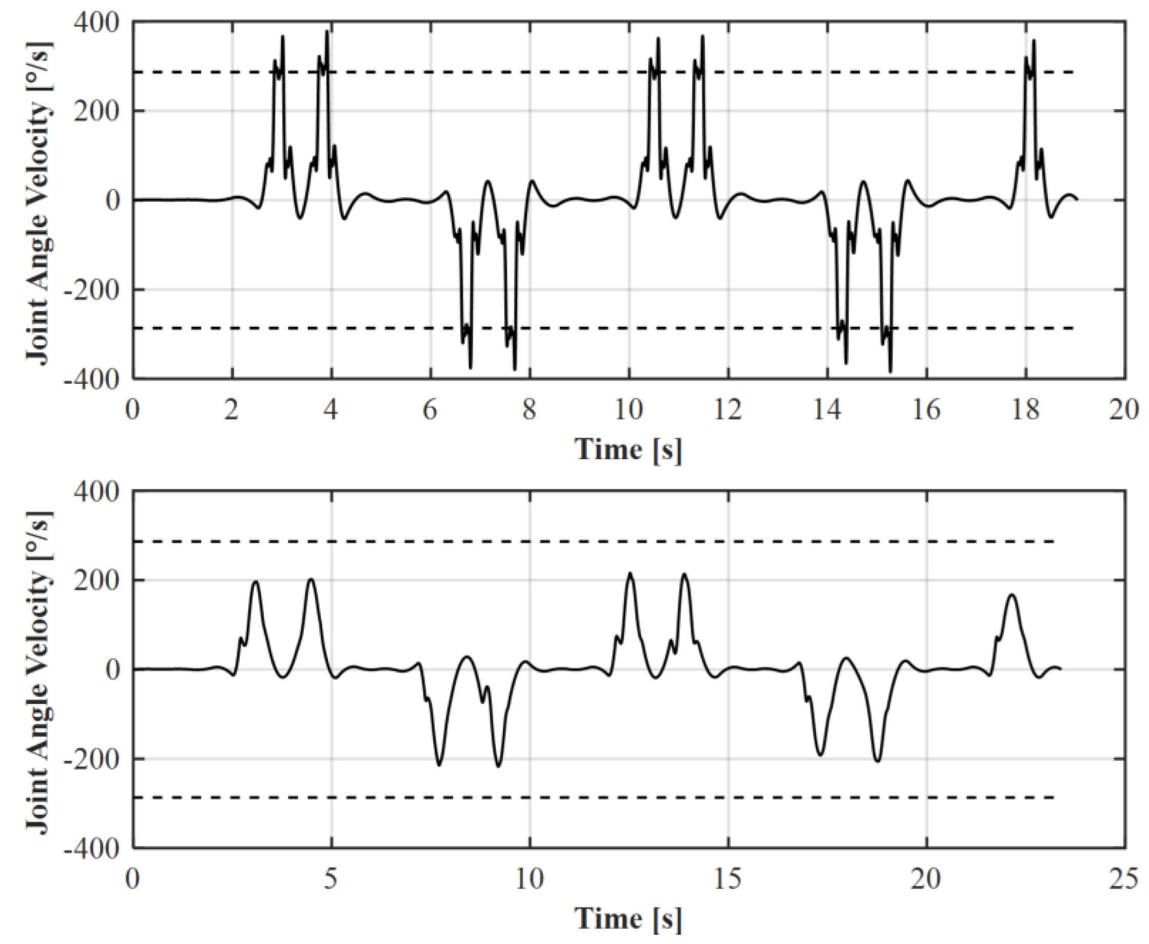
It was shown that the robot executability can be ensured if the selected path velocity leads to joint velocities that are not executable by the robot. For this purpose, the path velocity was reduced at the corresponding sections. It should be mentioned that this reduction in the speed in the curved sections can have negative influences on the welding result. If welding parameters are not varied at the same time, material accumulation will occur. Figure 13 shows a changing path velocity while executing a narrow zigzag path with path velocity of 10 mm/s after optimization. Figure 14 shows the corresponding joint velocity of the 6th axis of Kuka KR6 before and after optimization. It can be shown that the maximum joint velocity was pushed under the joint limits.
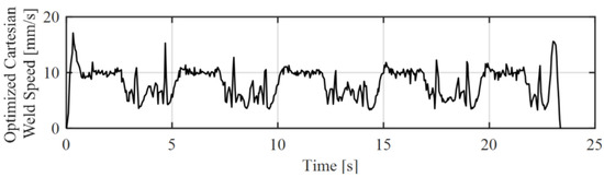
Figure 13.
Resulting Cartesian Path Speed after trajectory optimization.
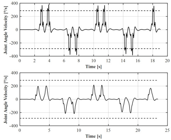
Figure 14.
Change in joint velocity of 6th axis before (top) and after (bottom) trajectory optimization.
Furthermore, the first experiments showed that the path velocity can be increased depending on the path curvature. The increase in the velocity is only possible up to the limits of the maximum joint velocities of the robot. Consequently, it must be started with a reduced initial path velocity. The optimization algorithm is designed in such a way that future experimental results on the combination of process and kinematic parameters will also allow simultaneous variation.
5. Conclusions
In order to commence a pure object manipulated WAAM process, a Gas Metal Arc welding process was constructed and synchronised with a robotic manipulator. Moreover, it was practically found feasible to accompany welding machine control algorithms with a robotic software environment. A tailored path and trajectory planning was implemented. The execution of complex multidirectional weld paths was thus made possible. After analysing the decisive results of the experiments, the risks associated with the GTAW welding process are considerably lesser with the help of current kinematic algorithms. Therefore, GTAW processes can be replaced by GMAW due to the advantages in WAAM processes. The replacement would require additional experiments to parametrize the process. It would not be necessary to re-establish the process parameter boundaries again for the new welding process. In addition, a stable and fixed torch was found to be technically advantageous for the integration of multiple sensors around it. Therefore, WAAM processes with pure object manipulation can be further researched in the direction of automatic process monitoring and controlling by deploying sensor-hardware in the system.
Author Contributions
Conceptualization, L.O., S.M. and M.S.; methodology, K.P. and M.S.; software, T.N. and J.W.; validation, K.P., L.O. and M.S.; investigation, K.P., M.S., T.N. and J.W.; writing—original draft preparation, K.P. and M.S.; writing—review and editing, R.S. and L.O.; visualization, K.P. and M.S.; supervision, R.S. and M.H.; project administration, R.S. and M.H.; advisory board, U.R. and B.C. All authors have read and agreed to the published version of the manuscript.
Funding
The research was funded by the German Research Foundation (DFG), Grant Id: 442454814.
Data Availability Statement
The data presented in this study are available on request from the corresponding author. The data are not publicly available due to the complex integration of the algorithms into an overall process that is not part of this publication. The pure algorithms are not executable without connection to other algorithms. However, the entire software project can be shared on request.
Acknowledgments
All presented investigations were conducted at RWTH Aachen University. For the sponsorship and the support, we wish to express our gratitude to German Research Foundation (DFG).
Conflicts of Interest
The authors declare no conflict of interest.
Abbreviations
The following abbreviations are used in this manuscript:
| WAAM | Wire Arc Additive Manufacturing |
| GMAW | Gas Metal Arc Welding |
| GTAW | Gas Tugsten Arc Welding |
| TIG | Tungsten Inert Gas |
| TCP | Tool Center Point |
| MDAM | Multidirectional Additive Manufacturing |
| OM-MDAM | Multidirectional Additive Manufacturing by Object Manipulation |
| DFG | German Research Foundation |
| ISF | Welding and Joining Institute of RWTH Aachen University |
| IGMR | Institute of Mechanism Theory, Machine Dynamics and Robotics of |
| RWTH Aachen University | |
| MDPI | Multidisciplinary Digital Publishing Institute |
| JMMP | Journal of Manufacturing and Material Science |
References
- Wahsh, L.M.; ElShater, A.E.; Mansour, A.K.; Hamdy, F.A.; Turky, M.A.; Azzam, M.O.; Salem, H.G. Parameter Selection for Wire Arc Additive Manufacturing (WAAM) Process. In Proceedings of the Materials Science and Technology 2018 (MS&T18), Columbus, OH, USA, 14–18 October 2018. [Google Scholar] [CrossRef]
- Ford, S.; Despeisse, M. Additive manufacturing and sustainability: An exploratory study of the advantages and challenges. J. Clean. Prod. 2016, 137, 1573–1587. [Google Scholar] [CrossRef]
- Thompson, M.K.; Moroni, G.; Vaneker, T.; Fadel, G.; Campbell, R.I.; Gibson, I.; Bernard, A.; Schulz, J.; Graf, P.; Ahuja, B.; et al. Design for Additive Manufacturing: Trends, opportunities, considerations, and constraints. CIRP Ann. 2016, 65, 737–760. [Google Scholar] [CrossRef] [Green Version]
- Reisgen, U.; Stein, L. Fundamentals of Joining Technology Welding, Brazing and Adhesive Bonding: Welding, Brazing and Adhasive Bonding; Fachbuchreihe Schweißtechnik, DVS Media: Düsseldorf, Germany, 2016; Volume Band 161. [Google Scholar]
- Yuan, L.; Pan, Z.; Ding, D.; Yu, Z.; van Duin, S.; Li, H.; Li, W.; Norrish, J. Fabrication of metallic parts with overhanging structures using the robotic wire arc additive manufacturing. J. Manuf. Process. 2021, 63, 24–34. [Google Scholar] [CrossRef]
- Ding, D.; Pan, Z.; Cuiuri, D.; Li, H. A tool-path generation strategy for wire and arc additive manufacturing. Int. J. Adv. Manuf. Technol. 2014, 73, 173–183. [Google Scholar] [CrossRef] [Green Version]
- Ding, D.; Pan, Z.; Cuiuri, D.; Li, H. A practical path planning methodology for wire and arc additive manufacturing of thin-walled structures. Robot. Comput.-Integr. Manuf. 2015, 34, 8–19. [Google Scholar] [CrossRef] [Green Version]
- Hascoët, J.Y.; Querard, V.; Rauch, M. Interests of 5 axis toolpaths generation for Wire Arc Additive Manufacturing of aluminum alloys. J. Mach. Eng. 2017, 17, 51–65. [Google Scholar]
- Reisch, R.; Hauser, T.; Kamps, T.; Knoll, A. Robot Based Wire Arc Additive Manufacturing System with Context-Sensitive Multivariate Monitoring Framework. Procedia Manuf. 2020, 51, 732–739. [Google Scholar] [CrossRef]
- Schmitz, M.; Wiartalla, J.; Gelfgren, M.; Mann, S.; Corves, B.; Hüsing, M. A Robot-Centered Path-Planning Algorithm for Multidirectional Additive Manufacturing for WAAM Processes and Pure Object Manipulation. Appl. Sci. 2021, 11, 5759. [Google Scholar] [CrossRef]
- Frazier, W.E. Metal Additive Manufacturing: A Review. J. Mater. Eng. Perform. 2014, 23, 1917–1928. [Google Scholar] [CrossRef]
- Michel, F.; Lockett, H.; Ding, J.; Martina, F.; Marinelli, G.; Williams, S. A modular path planning solution for Wire + Arc Additive Manufacturing. Robot. Comput.-Integr. Manuf. 2019, 60, 1–11. [Google Scholar] [CrossRef]
- Ma, G.; Zhao, G.; Li, Z.; Xiao, W. A Path Planning Method for Robotic Wire and Arc Additive Manufacturing of Thin-Walled Structures with Varying Thickness. IOP Conf. Ser. Mater. Sci. Eng. 2019, 470, 012018. [Google Scholar] [CrossRef]
- Nguyen, L.; Buhl, J.; Bambach, M. Multi-bead Overlapping Models for Tool Path Generation in Wire-Arc Additive Manufacturing Processes. Procedia Manuf. 2020, 47, 1123–1128. [Google Scholar] [CrossRef]
- Reisgen, U.; Mann, S.; Oster, L.; Lozano, P.; Sharma, R. Study on Workpiece and Welding Torch Height Control for Polydirectional WAAM by Means of Image Processing. In Proceedings of the 2019 IEEE 15th International Conference on Automation Science and Engineering (CASE), Vancouver, BC, Canada, 22–26 August 2019; pp. 6–11. [Google Scholar] [CrossRef]
- Yuan, L.; Ding, D.; Pan, Z.; Yu, Z.; Wu, B.; van Duin, S.; Li, H.; Li, W. Application of Multidirectional Robotic Wire Arc Additive Manufacturing Process for the Fabrication of Complex Metallic Parts. IEEE Trans. Ind. Inform. 2020, 16, 454–464. [Google Scholar] [CrossRef]
- Siciliano, B.; Sciavicco, L.; Villani, L.; Oriolo, G. Robotics: Modelling, Planning Furthermore, Control; Advanced Textbooks in Control and Signal Processing Series; Springer: London, UK, 2009. [Google Scholar]
- Liberini, M.; Astarita, A.; Campatelli, G.; Scippa, A.; Montevecchi, F.; Venturini, G.; Durante, M.; Boccarusso, L.; Minutolo, F.M.C.; Squillace, A. Selection of Optimal Process Parameters for Wire Arc Additive Manufacturing. Procedia CIRP 2017, 62, 470–474. [Google Scholar] [CrossRef]
- Kraft, D. A Software Package for Sequential Quadratic Programming; Deutsche Forschungs- und Versuchsanstalt für Luft- und Raumfahrt Köln: Cologne, Germany, 1988. [Google Scholar]
- Kraft, D. Algorithm 733: TOMP–Fortran modules for optimal control calculations. ACM Trans. Math. Softw. (TOMS) 1994, 20, 262–281. [Google Scholar] [CrossRef]


Publisher’s Note: MDPI stays neutral with regard to jurisdictional claims in published maps and institutional affiliations. |
© 2021 by the authors. Licensee MDPI, Basel, Switzerland. This article is an open access article distributed under the terms and conditions of the Creative Commons Attribution (CC BY) license (https://creativecommons.org/licenses/by/4.0/).