Abstract
In this study, we investigated the formation of a protective coating on a face-centered cubic high-entropy alloy (HEA). The coating was formed by a diffusion coating method. In the conventional diffusion coating method, the degradation of the mechanical properties of the base material owing to prolonged high-temperature treatment is a major issue. Therefore, we formed a ceramic layer using spark plasma sintering (SPS), which suppresses grain growth with rapid heating and enables fast, low-temperature processing. The objective of this study was to form borides on the surface of CoCrFeMnNi HEAs using the SPS method and to investigate their properties. A CoCrFeMnNi HEA prepared by the casting method was used as the base material, and a powdered mixture of B4C and KBF4 was used as the boron source. The analysis of the surfaces of the SPS-treated samples revealed the formation of M2B, MB, and Mn3B4-type borides on the HEA surface. The surface hardness was 2000–2500 HV owing to the formation of a ceramic layer on the HEA surface, and elemental analysis showed that certain elements exhibited characteristic diffusion behaviors.
1. Introduction
High-entropy alloys (HEA) are multi-component alloys obtained by blending five or more metal elements in equiatomic fractions (5–35%) [1]. The presence of many elements in HEA leads to the formation of a single-phase solid solution and not intermetallic phases. In contrast to conventional alloys, where atoms of the base metal are likely to be surrounded by atoms of the same element, all atoms are surrounded by atoms of different elements in HEA [2]. This causes lattice distortion owing to the different sizes of the surrounding atoms. Consequently, HEA exhibit unique properties, such as an excellent high-temperature strength, a high tensile strength, and extremely slow diffusion speeds [3,4]. In particular, HEA are attracting attention as a means of increasing the strength of corrosion-resistant parts and reducing costs by increasing the service life of chemical plant equipment [5]. Another reason for the interest in HEA is that they can be used for the additive manufucturing, which has been an active research area in recent years [6].
However, in the CoCrFeMnNi system, which is a typical face-centered cubic (FCC) HEA, the hardness is as low as, or lower than, those of general steel materials [7,8], which hinders its practical applications. To overcome these disadvantages, various studies have been conducted on HEA [9,10,11], including research on hardening by surface modification treatment, which has been actively pursued [12,13,14,15]. Physical vapor deposition (PVD) and chemical vapor deposition (CVD) are methods for coating hard layers on metal surfaces; however, if the adhesion between the metal substrate and the deposited layer is poor, the hardened layer may peel off during use, thereby causing serious issues [16,17]. Therefore, we focused on the fabrication of a hard layer with excellent adhesion by forming a graded intermediate zone. The diffusion coating method involves the formation of a hard layer by thermochemically diffusing various elements from the surface into the base material, which simultaneously react with it. Using this method, a hard layer with excellent adhesion can be formed. One of the diffusion coating methods is boronizing (boron immersion) treatment, which can form borides with an excellent hardness and wear resistance [18,19,20,21], and this could help overcome the aforementioned limitations associated with HEA. However, in conventional boronizing treatment, the deterioration of the mechanical properties of the base material owing to high temperatures and prolonged treatment is an issue that needs to be addressed [22,23]. Therefore, the use of spark plasma sintering (SPS), which enables fast, low-temperature treatment by rapidly heating the sample through the direct application of an electric current to the powder, might accelerate the reaction and solve the slow diffusion issue peculiar to HEA [24,25,26]. In addition, various studies have been carried out on the boride layer that forms from boronizing treatment on various materials, such as steel, but there are few reports on the formation of boride layers on HEA. In this study, we formed a boride layer on a HEA using the SPS method and evaluated the properties of the HEA boride layer.
2. Materials and Methods
2.1. Materials
HEA CoCrFeMnNi was used as the sample material in this study. A 250 g ingot of the sample material was produced using the gas-atomized powder with a nominal atomic composition of Co20Cr20Fe20Mn20Ni20. After weighing, the powder was placed in a clay–graphite crucible and melted at 1873 K under an argon atmosphere. The powder that was used as the boron source was prepared by mixing B4C (average particle diameter: 0.5 μm; purity: 99%) and KBF4 in a mass ratio of 9:1. The HEA samples were made by cutting 5 mm slices from a Φ32 mm ingot and then cutting them into quarters. Prior to boronizing, the sample was polished to a surface finish of 600 grit, ultrasonically degreased in acetone, and dried in air.
2.2. Boronizing via SPS
The boronizing experiments were conducted with an SPS unit (SPS-1020, Sumitomo Coal Mining Co., Ltd, Tokyo, Japan, present; Fuji Electronic Industrial Co., Ltd, Saitama, Japan). Each sample was enclosed in a punch and die (inner diameter of 25 mm; graphite) containing the B4C + KBF4 powder mixture. First, boron source powder (0.5 g) was placed in the die first, following which the substrates were placed, and finally, 1.5 g of boron source powder was placed to provide a sufficient boron source on both the upper and lower surfaces of the substrates. The chamber was then evacuated to a pressure less than 10 Pa, and a large-pulsed current was applied. The treatment was performed for 60 min and 180 min at temperatures of 973, 1073, and 1173 K. The applied pressure was 11 MPa, and the heating rate was 80 K min−1. Once the treatment was completed, the samples were cooled to room temperature inside a furnace. The treatment temperature was continuously monitored using a thermocouple.
2.3. Characterization
The phase structure at each surface after treatment was determined by analyzing its entire area using X-ray diffraction (XRD; RINT-2550V, RIGAKU, Osaka, Japan). The X-ray diffractometer was equipped with a Cu-Kα radiation source operated at 40.0 kV and 300 mA, and the samples were scanned at 40.0 deg min−1. Cross-sections of the samples were prepared by cutting them using a low-speed saw, embedding them in a conductive thermosetting resin, and polishing the exposed surface. The hardness values of the cross-sections of the treated samples were measured using a Vickers microhardness tester (PMT-X7A, Matsuzawa, Akita, Japan) under a load of 0.1 N. Five indentations were made on each sample, and a three-point average value (excluding both the maximum and minimum values) was reported as the hardness. The cross-sectional microstructural and compositional analyses of the treated samples were performed using electron probe microanalysis (EPMA: JXA-8230, JEOL, Tokyo, Japan). As a pretreatment for the analysis, the cross-sectional embedded specimens were buffed, electrolytically etched with 5% nitric acid, and then ultrasonically cleaned with acetone.
3. Results and Discussion
3.1. XRD
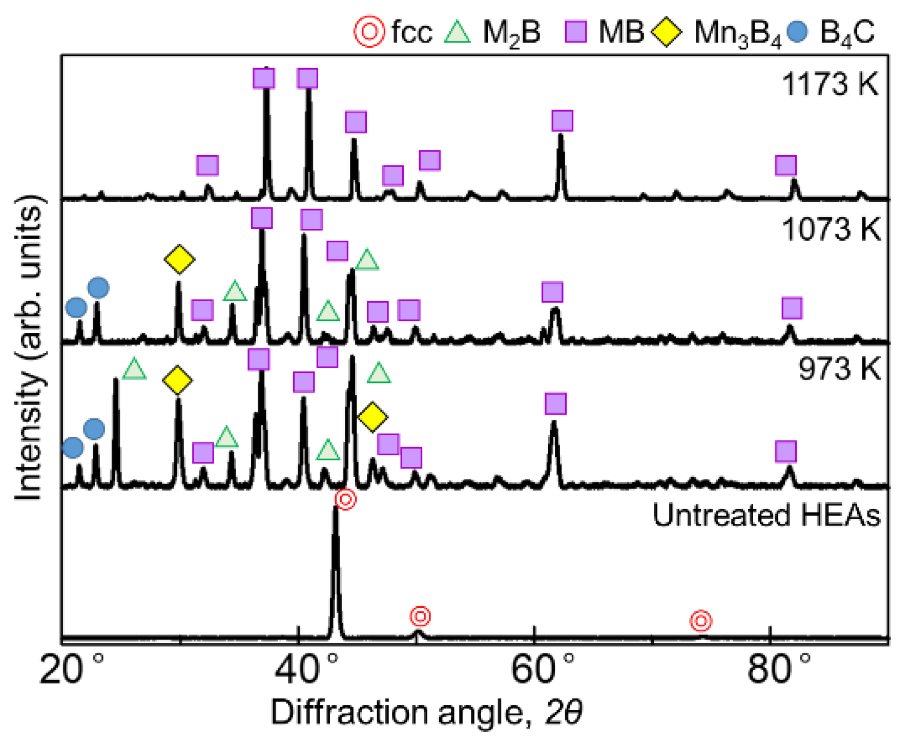
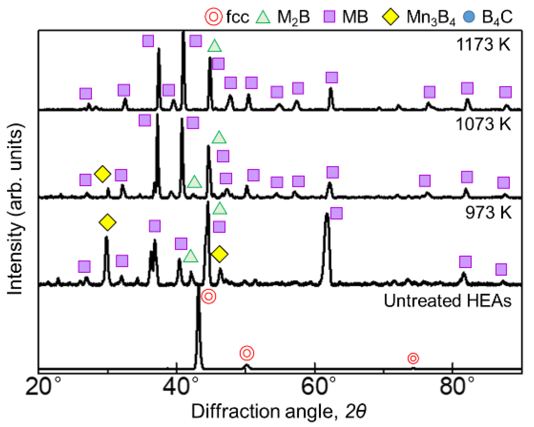
Figure 1 and Figure 2 show the results of XRD analysis of the sample surface after the boronizing treatment for 60 min and 180 min, respectively. Figure 1 shows diffraction lines from borides with the general formulas M2B, MB, and Mn3B4 as well as the boron source B4C at 973 and 1073 K for the 60 min treatment. At 1173 K, only the diffraction line of MB was identified. When the treatment time was 180 min, the borides formed at all temperatures were the same, but the presence of B4C, indicative of the seizure, was not identified. In the SPS method, when an electric current is applied to the powdered boron source, the current flows only to the surface of the B4C powder, which is not electrically conductive. Therefore, only the surface of the powder is heated, triggering mutual diffusion occurrences between the B4C powder and the sample. The B4C powder adhered to the surface of the sample, leaving B4C powder residue on the sample surface after the treatment at 973 and 1073 K. Accordingly, as the reaction time increased, the decomposition of the B4C powder increased to a point where its diffraction lines could no longer be identified. The MB-type borides formed when experimenting on the boronizing of the AlCoCrFeNi [27] and AlCoCrFeMnNiB HEA systems [28] were (Cr0.4Mn0.6)B (01-079-2851), (Fe0.4Mn0.6)B (01-079-2868), and (CrFe)B2 (01-079-2850), while the M2B-type boride formed was Ni2(Co0.67B0.33) (01-081-3360); consequently, we believe that similar complex borides are formed in this experiment.

Figure 1.
XRD patterns of the boronized samples obtained via treatment for 60 min at 973–1173 K.
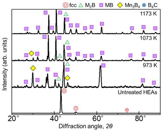
Figure 2.
XRD patterns of the boronized samples obtained via treatment for 180 min at 973–1173 K.
3.2. Cross-Sectional Hardness
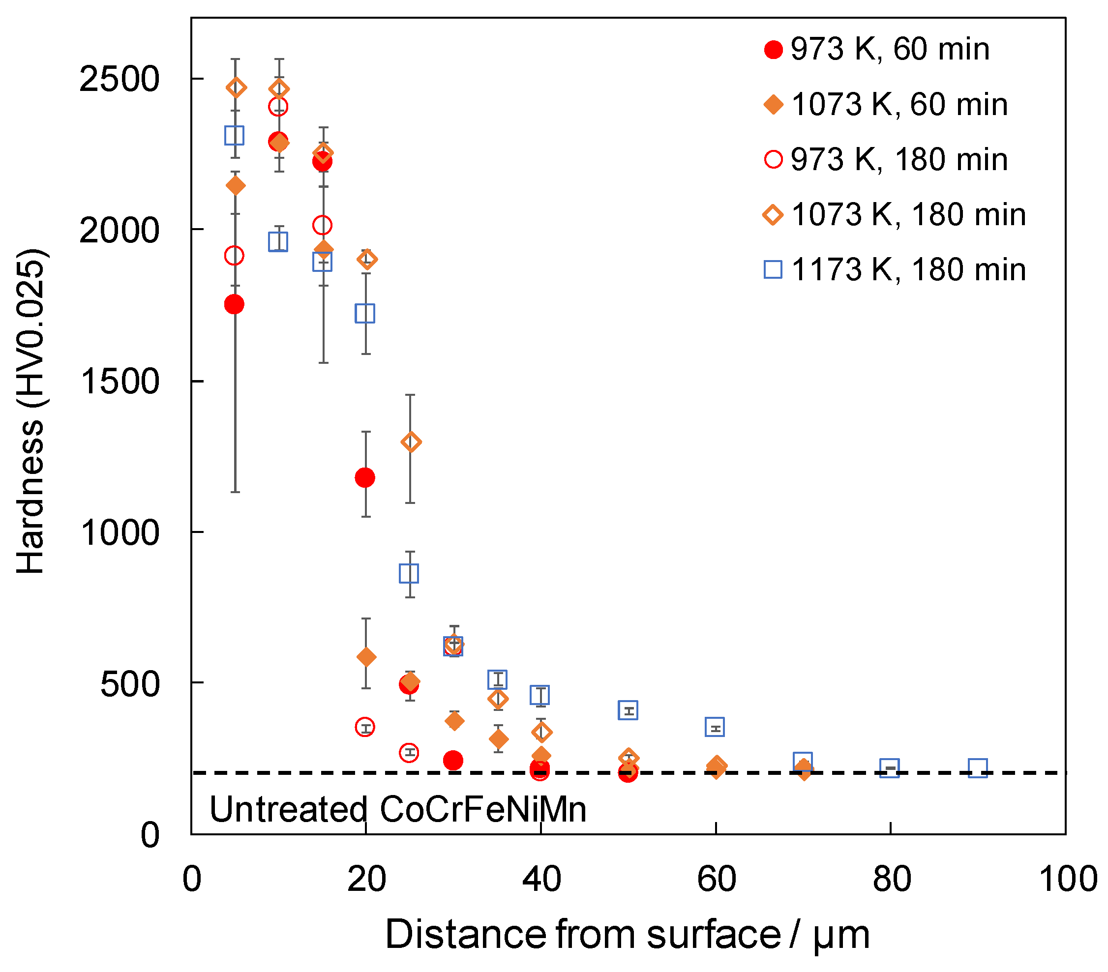
Figure 3 shows the cross-sectional hardness profile for each treatment condition. The samples that were boronized for 60 min at 1173 K were not tested because of non-uniformity in the thickness of their boride layers. For samples that were treated at 973 K, the hardness was higher at 10 µm from the surface than at 5 µm, indicating that interdiffusion between B4C and the sample did not occur sufficiently at 973 K. The coating at 5 µm from the surface was unstable because of the mixture of boride and non-boride near the surface. It is suggested that the unstable hardness of the upper surface at 973 K was improved by the treatment at temperatures above 1073 K because of the effect of increasing the treatment temperature. This is attributed to the accelerated reaction caused by the increase in the processing temperature. However, when the SPS method is used, the higher processing temperature is due to two specific effects: one is the higher Joule heat generated between the boron source powders, and the other is that the non-conductive B4C becomes conductive. Firstly, in the FAST method, which has a sintering mechanism similar to the SPS method, it is known that the Joule heat generated between the powders also increases as the current value increases [29]. Additionally, in the SPS method, the applied current increases as the processing temperature increases. Therefore, it is thought that the Joule heat generated between the boron source powders increases with an increase in the applied current as the processing temperature rises, causing the boronizing reaction to accelerate and the hardness to increase. Secondly, as the conductivity of B4C increased, the current applied to the boron source increased, suggesting that the reaction proceeded as the powder reached a higher state of activity. In addition, the hardness of the alloy increased with an increase in the treatment time at 1073 K. In conjunction with the results shown in Figure 1, it can be seen that after 60 min, B4C still remained on the surface and the reaction was still in progress; however, after 180 min, B4C was not detected, indicating that the reaction was complete and denser borides were formed, resulting in an increase in hardness. In the previously demonstrated boronizing of a AlCoCrFeMnNiB HEA [28], a hardened layer of approximately 2000 HV was obtained for a treatment for 240 min at 1173 K, and a hardened layer of approximately 20 µm was obtained for a treatment for 180 min at 1173 K. Both in this case and in the present study, similar thicknesses were obtained with similar treatment temperatures and short treatment times. These results indicate that the use of SPS accelerated the reaction and shortened the processing time. It has been observed that in the boronizing process using SPS, the boron source powder becomes active when an electric current is applied, and the reaction is accelerated owing to a decrease in the activation energy of the boronizing reaction [20,21]. In this study, the reaction was promoted in the same manner, and it can be considered that a boride layer of the same thickness could be obtained in a shorter time than that of the boronizing treatment using the general powder packing method.
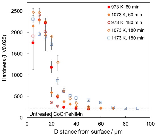
Figure 3.
Cross-sectional hardness profiles of boronized samples.
3.3. Elemental Analysis
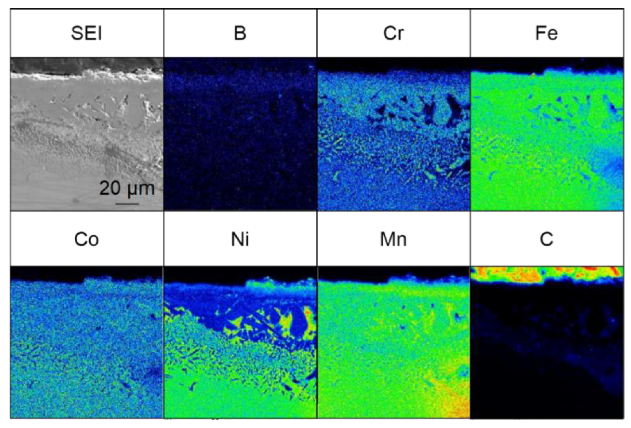
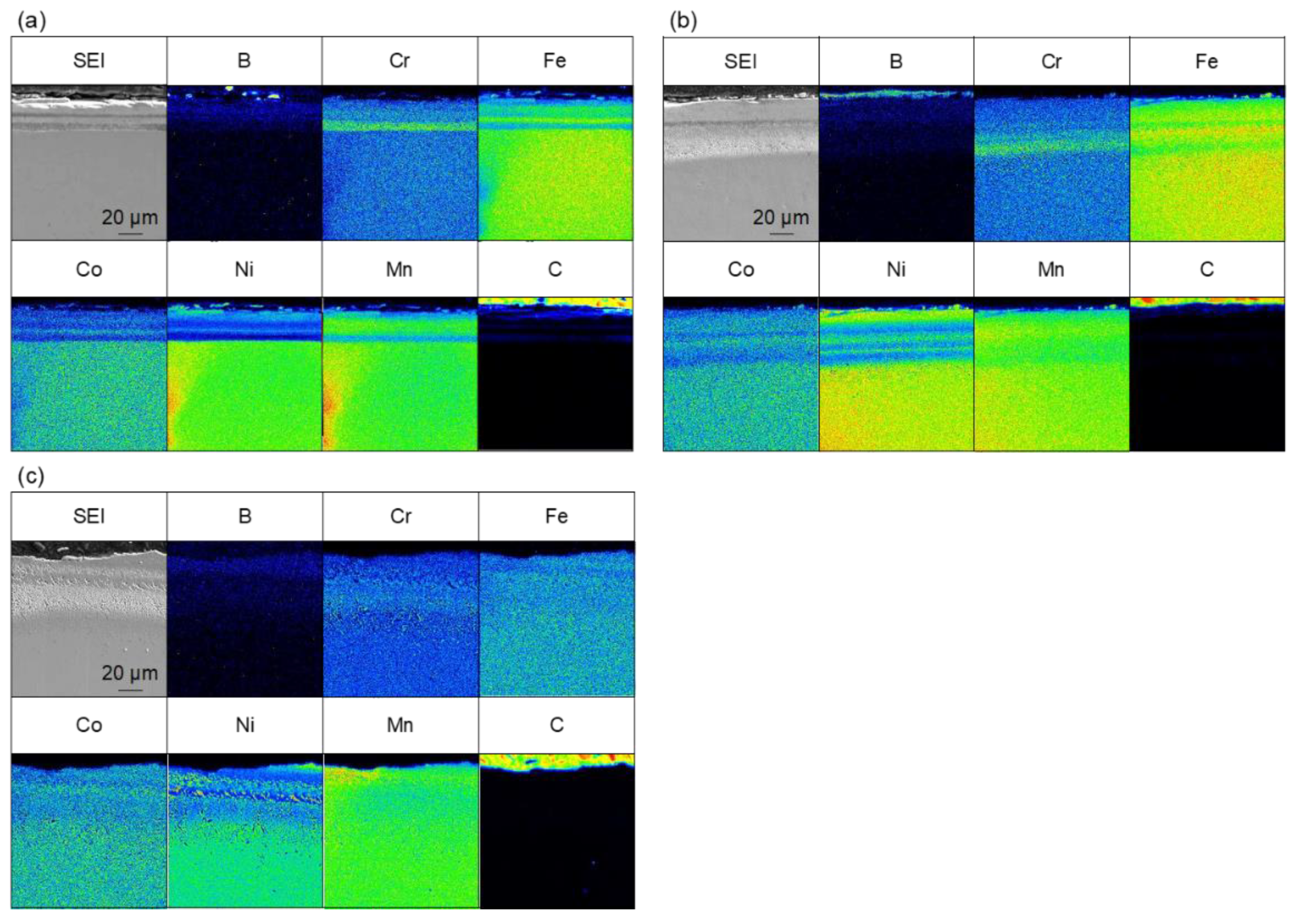
Figure 4 shows the results of the elemental analysis of the cross-section of the sample treated for 60 min at 973–1173 K. Boron-enriched regions of approximately 5 µm at 973 K, 18 µm at 1073 K, and 25 µm at 1173 K were observed; the thickness of the boron-enriched region increased with increasing temperature. In Figure 4, nickel enrichment was observed on the top of the boride layer at all treatment temperatures, and chromium enrichment was detected at the bottom of the boride layer for the treatments at 1073 and 1173 K. We believe that this segregation is due to the difference in the diffusion rate of each element in the boride layer. The diffusion rates of various elements in boride layers have been investigated [30], and it has been reported that the diffusion rate of Ni in the boride layer is extremely low, while the diffusion rates of other metals, such as Cr and Mn, are approximately the same as the growth rate of the boride layer. This suggests that as the boride layer grew, the Ni was left behind at the top of the layer because of its limited diffusion, whereas Cr and other elements diffused through the boride layer and were enriched at the bottom of the boride layer. The diffusion of carbon from the boron source powder does not occur during the boronizing treatment while using the conventional powder packing method; therefore, the observation of carbon diffusion into this sample (Figure 4) suggests that the diffusion of boron occurs by a decomposition of B4C when SPS is used as the boronizing method. In addition to the flat boride layer shown in Figure 4, precipitate-like regions were scattered throughout the layer in the case of the treatment for 60 min at 1173 K. The elemental analysis results for the precipitate-like regions are shown in Figure 5. The segregation of Ni, Cr, and carbon is especially noticeable. In the SPS method, the sample was enclosed in a graphite die, and the temperature was raised by Joule heating due to the application of a pulsed current; therefore, the higher the processing temperature, the higher the applied power. At the higher processing temperature (1173 K), a higher current and voltage were applied to the sample, which strengthened the effect of electric field diffusion and promoted the diffusion of boron and the faster growth rate of the boride layer. Therefore, the difference in the diffusion rate of the elements becomes more pronounced, and segregation is assumed to occur in the form of precipitates rather than layers.
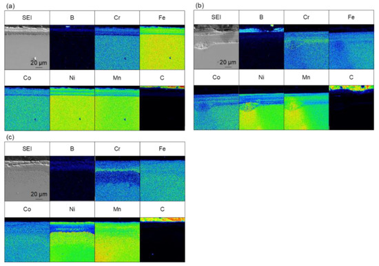
Figure 4.
Cross-sectional SEM images and EPMA elemental mapping images for samples that were boronized for 60 min at (a) 973 K, (b) 1073 K and (c) 1173 K.

Figure 5.
Cross-sectional SEM images and EPMA elemental mapping images for the precipitate region of samples that were boronized for 60 min at 1173 K.
Figure 6 shows the results of the elemental analysis of samples that were treated for 180 min at 973–1173 K. In the 180 min treatment, boron enrichment regions of thicknesses of approximately 16 µm at 973 K, 20 µm at 1073 K, and 18 µm at 1173 K were observed. The boride layer was the thickest for the 180 min at 973 K treatment, but there was no significant difference in the thickness of the boride layer in the case of treatments for 180 min at 973–1173 K. We also consider that the thickness of the boride layer did not change with the increasing treatment time at treatment temperatures above 1073 K because of the sluggish diffusion effect of HEAs. The diffusion rate decreases when an alloy reaches the composition of a HEA [31], which has been observed in studies on HEA boriding [13]. These results show that the boronizing reaction did not progress sufficiently after 60 min at 973 K, and the boride layer became thicker as the treatment time increased. On the other hand, at 1073 K and above the reaction progressed to some extent even after 60 min. We assume that the thickness of the boride layer did not change because the diffusion of new B atoms was slow owing to the low diffusion rate of HEAs. However, the results obtained in this study are insufficient to prove this; therefore, further investigation is required. Boron diffusion regions were also observed at 1073 and 1173 K. As shown in Figure 5, the precipitate-like regions observed for the treatment for 60 min at 1173 K were not observed for the treatment for 180 min at 1173 K, and the boride layer was uniform. This is hypothesized to be due to the diffusion of segregated elements as the treatment time increased.
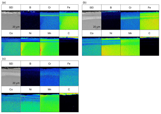
Figure 6.
Cross-sectional SEM images and EPMA elemental mapping images for samples that were boronized for 180 min at (a) 973 K, (b) 1073 K, and (c) 1173 K.
4. Conclusions
In this study, borides were simultaneously formed on the surface of a CoCrFeMnNi HEA via SPS. The properties and microstructure of the treated samples were investigated using XRD, cross-sectional hardness tests, and EPMA. The following findings were obtained:
- (1)
- A modified layer consisting of M2B, MB, and Mn3B4 can be fabricated on a CoCrFeMnNi HEA surface under all treatment conditions using the SPS method.
- (2)
- The boronized samples showed improved hardness compared to those of the CoCrFeMnNi HEA substrate. The hardness near the upper surface tended to increase as the treatment temperature and time increased.
- (3)
- The thickness of the boronized layer increased with the increasing treatment time at 973 K but did not change significantly at 1073 and 1173 K when the treatment time was varied.
Author Contributions
H.N. and A.N. conceived and designed the experiments and wrote the paper. H.N. performed the experiments and analyzed the data. A.N. directed the research and contributed to the discussion and interpretation of the results. All authors have read and agreed to the published version of the manuscript.
Funding
This work was supported by JSPS KAKENHI Grant Number 21K04723.
Institutional Review Board Statement
Not applicable.
Informed Consent Statement
Not applicable.
Data Availability Statement
Not applicable.
Acknowledgments
The authors wish to express their gratitude to Toru Maruyama, Kansai University, for suppling cast ingot samples of CoCrFeMnNi HEA.
Conflicts of Interest
The authors declare no conflict of interest.
References
- Yeh, J.W.; Chen, S.K.; Lin, S.J.; Gan, J.Y.; Chin, T.S.; Shun, T.T.; Tsau, C.H.; Chang, S.Y. Nanostructured high-entropy alloys with multiple principal elements: Novel alloy design concepts and outcomes. Adv. Eng. Mater. 2004, 6, 299–303. [Google Scholar] [CrossRef]
- Eißmann, N.; Klöden, B.; Weißgärber, T.; Kieback, B. High-entropy alloy CoCrFeMnNi produced by powder metallurgy. Powder Metall. 2017, 60, 184–197. [Google Scholar] [CrossRef]
- Yeh, J.W. Recent progress in high entropy alloys. Ann. Chim. Sci. Mat. 2006, 31, 633–648. [Google Scholar] [CrossRef]
- Li, Z.; Pradeep, K.G.; Deng, Y.; Raabe, D.; Tasan, C.C. Metastable high-entropy dual-phase alloys overcome the strength–ductility trade-off. Nature 2016, 534, 227–230. [Google Scholar] [CrossRef] [PubMed]
- Kuwabara, K.; Ogoshi, K.; Otsubo, Y.; Chen, M.; Fujieda, T. Additive manufacturing of high entropy alloys. Materia 2018, 57, 328–332. [Google Scholar] [CrossRef] [Green Version]
- Qiu, Z.; Yao, C.; Feng, K.; Li, Z.; Chu, P.K. Cryogenic deformation mechanism of CrMnFeCoNi high-entropy alloy fabricated by laser additive manufacturing process. Int. J. Lightweight Mater. Manuf. 2018, 1, 33–39. [Google Scholar] [CrossRef]
- Schuh, B.; Mendez-Martin, F.; Völker, B.; George, E.P.; Clemens, H.; Pippane, R.; Hohenwarter, A. Mechanical properties, microstructure and thermal stability of a nanocrystalline CoCrFeMnNi high-entropy alloy after severe plastic deformation. Acta Mater. 2015, 96, 258–268. [Google Scholar] [CrossRef] [Green Version]
- Kashaev, N.; Ventzke, V.; Stepanov, N.; Shaysultanov, D.; Sanin, V.; Zherebtsov, S. Laser beam welding of a CoCrFeNiMn-type high entropy alloy produced by self-propagating high-temperature synthesis. Intermetallics 2018, 96, 63–71. [Google Scholar] [CrossRef]
- Chen, S.; Oh, H.S.; Gludovatz, B.; Kim, S.J.; Park, E.S.; Zhang, Z.; Ritchie, R.O.; Yu, Q. Real-time observations of TRIP-induced ultrahigh strain hardening in a dual-phase CrMnFeCoNi high-entropy alloy. Nat. Commun. 2020, 11, 826. [Google Scholar] [CrossRef] [Green Version]
- Nakajo, H.; Nishimoto, A. Producing CrFeCoNiSi-based high entropy alloy by spark plasma sintering. Mater. Trans. 2021, 62, 1231–1238. [Google Scholar] [CrossRef]
- Eißmann, N.; Mühle, U.; Gaitzsch, U.; Walther, G.; Weißgärber, T.; Kieback, B. Precipitation hardening of high entropy alloy CoCrFeMnNi containing titanium. J. Alloy. Compd. 2021, 857, 157610. [Google Scholar] [CrossRef]
- Nishimoto, A.; Fukube, T.; Maruyama, T. Microstructural, mechanical, and corrosion properties of plasma-nitrided CoCrFeMnNi high-entropy alloys. Surf. Coat. Technol. 2019, 376, 52–58. [Google Scholar] [CrossRef]
- Cengiz, S. Effect of refractory elements on boronizing properties of the CoCrFeNi high entropy alloy. Int. J. Refract. Hard Met. 2021, 95, 105418. [Google Scholar] [CrossRef]
- Zhang, L.J.; Jiang, Z.K.; Zhang, M.D.; Fan, J.T.; Liu, D.J.; Yu, P.F.; Li, G.; Liua, R.P. Effect of solid carburization on the surface microstructure and mechanical properties of the equiatomic CoCrFeNi high-entropy alloy. J. Alloys Compd. 2018, 769, 27–36. [Google Scholar] [CrossRef]
- Karimoto, T.; Nishimoto, A. Plasma-nitriding properties of CoCrFeMnNi high-entropy alloys produced by spark plasma sintering. Metals 2020, 761, 10. [Google Scholar] [CrossRef]
- Kameoka, S.; Motonishi, S.; Uchida, H. Damage processes and substrate surface design for CVD diamond films. Surf. Coat. Technol. 2003, 169-170, 316–320. [Google Scholar] [CrossRef]
- Yin, X.; Gotman, I.; Klinger, L.; Gutmanas, E.Y. Formation of titanium carbide on graphite via powder immersion reaction assisted coating. Mater. Sci. Eng. A 2005, 396, 107–114. [Google Scholar] [CrossRef]
- Sahin, S.; Meric, C. Investigation of the effect of boronizing on cast irons. Mater. Res. Bull. 2002, 37, 971–979. [Google Scholar] [CrossRef]
- Petrova, R.S.; Suwattananont, N.; Samardzic, V. The effect of boronizing on metallic alloys for automotive applications. J. Mater. Eng. Perform. 2008, 17, 340–345. [Google Scholar] [CrossRef]
- Karimoto, T.; Nishimoto, A. Simultaneous boronizing and carburizing of titanium via spark plasma sintering. Mater. Trans. 2019, 60, 2378–2391. [Google Scholar] [CrossRef]
- Nishimoto, A.; Kubo, T. Boronizing of AISI 316L stainless steel using spark plasma sintering technique. Defect Diffus. Forum 2020, 405, 3–10. [Google Scholar] [CrossRef]
- Hoshiyama, Y.; Li, X.; Dong, H.; Nishimoto, A. Characterization of hot-steam oxidation tested chromosiliconized heat-resistant austenitic stainless steel. Mater. Trans. 2012, 53, 1090–1093. [Google Scholar] [CrossRef] [Green Version]
- Sizov, I.; Mishigdorzhiyn, U.; Leyens, C.; Vetter, B.; Fuhrmann, T. Influence of thermocycle boroaluminising on strength of steel C30. Surf. Eng. 2014, 30, 129–133. [Google Scholar] [CrossRef]
- Badica, P.; Crisan, A.; Aldica, G.; Endo, K.; Borodianska, H.; Togano, K.; Awaji, S.; Watanabe, K.; Sakka, Y.; Vasylkiv, O. ‘Beautiful’ unconventional synthesis and processing technologies of superconductors and some other materials. Sci. Technol. Adv. Mater. 2011, 12, 013001. [Google Scholar] [CrossRef] [Green Version]
- Badica, P.; Aldica, G.V.; Burdusel, M.; Borodianska, H.; Sakka, Y.; Vasylkiv, O. Challenges of nanostructuring and functional properties for selected bulk materials obtained by reactive spark plasma sintering. Jpn. J. Appl. Phys. 2014, 53, 05FB22. [Google Scholar] [CrossRef]
- Nagasawa, R.; Asayama, Y.; Nakayama, T. Acceleration of metal-atom diffusion in electric field at metal/insulator interfaces: First-principles study. Jpn. J. Appl. Phys. 2018, 57, 04FB05. [Google Scholar] [CrossRef] [Green Version]
- Karakaş, M.S.; Günen, A.; Çarboğ, C.; Karac, Y.; Demir, M.; Altınay, Y.; Erdoğan, A. Microstructure, some mechanical properties and tribocorrosion wear behavior of boronized Al0.07Co1.26Cr1.80Fe1.42Mn1.35Ni1.10 high entropy alloy. J. Alloy. Compd. 2021, 886, 161222. [Google Scholar] [CrossRef]
- Günen, A. Tribocorrosion behavior of boronized Co1.19Cr1.86Fe1.30Mn1.39Ni1.05Al0.17B0.04 high entropy alloy. Surf. Coat. Technol. 2021, 421, 1274426. [Google Scholar] [CrossRef]
- Meng, B.; Zhang, Z.Y.; Ma, L.Y.; Wan, M. Effect of sintering temperature on microstructure and mechanical properties of Inconel 718 superalloy prepared by micro-FAST. Mater. Sci. Eng. A 2022, 836, 142733. [Google Scholar] [CrossRef]
- Litoria, A.K.; Figueroa, C.A.; Bim, L.T.; Pruncu, C.I.; Joshi, A.A.; Hosmani, S.S. Pack-boriding of low alloy steel: Microstructure evolution and migration behaviour of alloying elements. Philos. Mag. 2020, 100, 353–378. [Google Scholar] [CrossRef]
- Tsai, M.H.; Yeh, J.W. High-entropy alloys: A critical review. Mater. Res. Lett. 2014, 2, 107–123. [Google Scholar] [CrossRef]

Publisher’s Note: MDPI stays neutral with regard to jurisdictional claims in published maps and institutional affiliations. |
© 2022 by the authors. Licensee MDPI, Basel, Switzerland. This article is an open access article distributed under the terms and conditions of the Creative Commons Attribution (CC BY) license (https://creativecommons.org/licenses/by/4.0/).