Article

Influence of the L-PBF Process Atmosphere on the Microstructure and Tensile Properties of AISI 318LN Duplex Stainless Steel

Institute for Materials Applications in Mechanical Engineering, RWTH Aachen University, Augustinerbach 4, 52062 Aachen, Germany
*
Author to whom correspondence should be addressed.
J. Manuf. Mater. Process. 2022, 6(2), 32; https://doi.org/10.3390/jmmp6020032
Submission received: 9 February 2022 / Revised: 5 March 2022 / Accepted: 9 March 2022 / Published: 10 March 2022
(This article belongs to the Special Issue Advances in Metal Additive Manufacturing/3D Printing)

Abstract

:
Duplex stainless steels (DSSs) have excellent mechanical properties, owing to their austenitic-ferritic microstructure. The phase equilibrium strongly depends on solidification conditions and chemical composition, where elemental nitrogen significantly stabilizes the austenitic phase. When DSSs are processed by laser powder bed fusion (L-PBF) under an argon atmosphere, the rapid cooling rates result in an undesirable fully ferritic microstructure. To better understand the microstructure formation, this study examined the influence of the L-PBF process atmosphere on the porosity, microstructure, and mechanical properties of DSS AISI 318LN. Gaseous argon and nitrogen were used as a protective atmosphere, and specimens were analyzed in the as-built and post-processed conditions via optical and electron microscopy, electron backscatter diffraction, and tensile testing. Specimens processed under a nitrogen atmosphere showed a lower initial density in the as-built conditions, and tended to form more lack-of-fusion and gas pores compared to specimens processed under argon. The different defect types in nitrogen-processed specimens were still present after solution-annealing and quenching, leading to a 13% lower tensile strength and 43% lower elongation at fracture. Differences in phase equilibrium caused by the process atmosphere could not be established. All differences in porosity can be minimized by hot isostatic pressing, thus resulting in comparable mechanical properties of argon- and nitrogen-processed specimens.

1. Introduction

Interest in additive manufacturing (AM) for industrial applications has increased among the research community over the past several years. AM allows for direct production, from CAD data, of highly complex structures and components that otherwise could not be machined through conventional manufacturing techniques [1]. Laser powder bed fusion (L-PBF) is of special interest because it is among the most promising AM processes for the production of metallic components with very high accuracy [2]. L-PBF is a well-established process and manufacturing route for stainless steels (SSs). The most commonly used types of SS in L-PBF are austenitic grades, such as AISI 316L (DIN X2CrNiMo17-12-2, material no. 1.4404) and precipitation-hardening martensitic AISI 630 (DIN X5CrNiCuNb17-4-4, material no. 1.4548), whereas duplex stainless steels (DSSs), such as AISI 318LN (DIN X2CrNiMoN22-5-3, material no. 1.4462) and AISI F53 (DIN X2CrNiMoN25-7-4, material no. 1.4410), have rarely been investigated [3]. DSSs have higher strength than fully austenitic SS, and greater impact toughness than fully ferritic steel, as well as excellent corrosion resistance against intergranular, pitting, and crevice corrosion. These outstanding properties arise from the duplex microstructure comprising nearly equal phase fractions of ferrite and austenite. However, DSSs are also prone to embrittlement caused by undesirable precipitates, such as carbides, nitrides, and σ- and χ-phases [4], thus indicating the importance of L-PBF parameters, solidification conditions, and subsequent thermal post-processing [5,6,7,8]. When processed via L-PBF, DSSs tend to solidify predominantly in a ferritic microstructure, whereas small amounts of austenite precipitate along the grain boundaries in the form of Widmanstätten plates [6]. This finding has been attributed to the rapid solidification of molten material, with typical cooling rates between 104 K s−1 and 106 K s−1 in the L-PBF process [2,9]. Subsequent solution-annealing and quenching (SA + Q) treatment leads to the precipitation of secondary austenite along the grain boundaries [10]. The obtainable phase equilibrium between austenite and ferrite strongly depends on the solution-annealing temperature, and can range from 40:60%-vol. to 50:50%-vol. for a temperature range between 950 °C and 1100 °C [8]. A loss of austenite-stabilizing elements—such as nitrogen or carbon, owing to vaporization during the L-PBF process—markedly influences the phase equilibrium and, therefore, decreases the obtainable austenite phase fraction to well below 40%-vol. [5].
The substantial influence of alloying elements on phase equilibrium and solidification in DSSs is well known, particularly for nitrogen [11]. When cooling from the liquid phase, DSS begins to solidify into a fully delta-ferritic microstructure. After full solidification and slow cooling, in contrast to the high cooling rates in L-PBF, diffusion-controlled solid-state precipitation of austenite begins. The phase fraction of austenite gradually increases with declining temperatures, and ultimately reaches a maximum stable fraction after quenching [12]. The stability of the austenitic and ferritic phases depends on the chemical composition. Elements such as Cr, Mo, Si, and W stabilize the ferritic phase, whereas elements such as Ni, Mn, N, and C stabilize the austenitic phase. The effectiveness of these elements can be expressed according to the chromium equivalent for ferrite-stabilizing elements and the nickel equivalent for austenite-stabilizing elements [13,14].
Ni eq   = Ni + 30 × C + 30 × N + 0.5 x × Mn
Cr eq   = Cr + Mo + 1.5 × Si + 0.5 × Nb
Because nitrogen has a factor of 30 in the nickel equivalent, this element is important in the austenite phase fraction and equilibrium. Therefore, L-PBF-induced local or global variation in composition results in microstructural inhomogeneity.
Furthermore, nitrogen has major effects on the mechanical properties of DSS, owing to strengthening effects caused by solid–solution strengthening and nitrogen-enhanced grain size strengthening [15]. The positive influence of nitrogen as an alloying element in steels was first reported by Frehser et al. [16], and also applies to steels processed via L-PBF [17,18,19].
To prevent the loss of nitrogen due to vaporization during the AM process, the shielding gas can be changed from standard argon to gaseous nitrogen, as described by Bermejo et al. for laser metal deposition of DSS AISI 318LN [20]. The same strategy can be applied to the L-PBF process, although the nitrogen concentration in specimens has not been the main focus of prior studies, and L-PBF of DSS has not been investigated under a nitrogen atmosphere. Pauzon et al. investigated the effect of L-PBF process gas on the properties of austenitic AISI 316L SS [21]; they observed no loss of elemental nitrogen when gaseous argon, nitrogen, and helium were used as the process gas, and maximal nitrogen concentrations within the specimens when nitrogen was used as the process gas. However, the nitrogen concentration was not found to be correlated with better mechanical properties, because no differences were observed between specimens processed under argon and nitrogen atmospheres in tensile tests. Similarly, no differences in porosity could be observed, regardless of the process gas [22]. Studies on the influence of the process gas on the properties of L-PBF-processed AlSi10Mg and AlSi12 have revealed little-to-no influence on microstructure, porosity, or mechanical properties [23,24,25]. However, Dai et al. reported a substantial difference in melt pool fluctuation behavior, with a decreased tendency for keyhole defect formation when argon was used [26]. Dong et al. reported a higher initial density and higher nitrogen concentrations in specimens when nitrogen was used as the process gas for the L-PBF of tungsten, and mechanical properties surpassing the values for specimens processed under argon [27]. Pauzon et al. have also reported on the influence of the process gas during L-PBF of Inconel 718, observing a nitrogen loss for all specimens, but a lower loss with high-purity nitrogen [28,29].
This study aimed at investigating process-gas-induced differences in AISI 318LN DSS processed under argon and nitrogen protective atmospheres with L-PBF. The investigations included high-resolution microstructural characterization by microscopy and electron backscatter diffraction, chemical analysis with special consideration of argon and nitrogen loss or pick-up, and static–mechanical testing via hardness and tensile testing. Because the phase fractions of austenite and ferrite are directly influenced by the nitrogen content, and are highly important in achieving the outstanding properties of DSSs, two subsequent post-processing routes for as-built AISI 318LN specimens were chosen: a single solution-annealing and quenching process, and an additional densification process via hot isostatic pressing before solution-annealing and quenching.

2. Materials and Methods
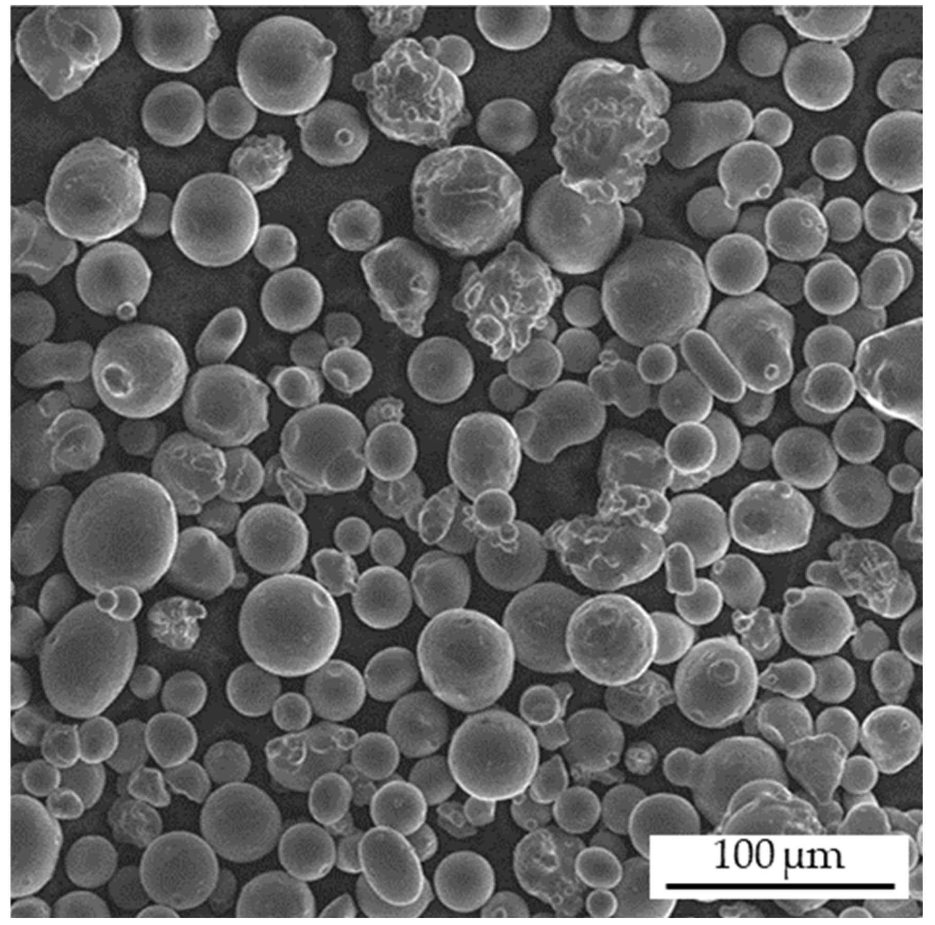
2.1. Material

In this study, gas-atomized AISI 318LN (DIN X2CrNiMoN22-5-3, material no. 1.4462) DSS steel powder was used. The atomizing process was conducted under a nitrogen atmosphere, and the powder was supplied by Deutsche Edelstahlwerke GmbH (Krefeld, Germany). The chemical composition of the powder (Table 1) was measured through optical emission spectroscopy with a SPECTROMAXx LMX07 instrument (SPECTRO Analytical Instruments GmbH, Kleve, Germany), whereas carbon and nitrogen contents were measured with a LECO CS300 (LECO Instrument GmbH, Moenchengladbach, Germany) CS analyzer as well as a Bruker GALILEO G8 (Bruker Corp., Billerica, MA, USA) ONH analyzer. The elemental composition according to the EN 10088-3 standard [30] indicated a powder composition within the defined ranges. The argon content in virgin powder and bulk specimens was measured with a Trace GC 600 (Thermo Fisher Scientific, Waltham, MA, USA) quadrupole mass analyzer at Bodycote Specialist Technologies Deutschland GmbH, according to the Swedish SS 118000:2018 standard [31]. The sample mass for argon measurements was 0.5–1.0 g, and the lower limit of detection was 0.049 ppm. The argon content was determined as the ratio between the detected argon mass and the specimen mass. In Figure 1, a scanning electron microscopy (SEM) image of the used powder is depicted. The powder particles were nearly spherical in shape, and very few satellites were observed. The desired particle size distribution of d10 = 26 µm, d50 = 39 µm, and d90 = 53 µm was achieved by sieving and determined using a Partica LA-950 particle size distribution analyzer (Horiba Ltd., Kyoto, Japan). The uniform particle size distribution is shown in Figure 2.

2.2. L-PBF Processing and Specimen Production

A Realizer SLM 100 machine (Realizer GmbH, Borchen, Germany) equipped with a pulsating ytterbium fiber laser with a wavelength λ = 1070 ± 2.5 nm and a maximum laser power of 200 W was used for the specimen production. Nitrogen 5.0 and argon 5.0, with a purity of 99.999%, were used as the protective atmosphere and to flush the build chamber, with a fluctuating excess pressure between 15–30 mbar above ambient pressure. The specimens were built with a layer thickness of 50 µm, a build plate preheating temperature of 200 °C, and a stripe scanning strategy, with a stripe width of 2.7 mm and stripe overlap of 0.1 mm. Each subsequent layer was rotated by 90°, while the interlayer time was approximately 45 s. Further parameters were selected according to a previous study using the same L-PBF machine [7]. A hatch distance of 100 µm, a laser power of 175 W, an exposure time ts of 36 µs, and a point distance dp of 40 µm were used, whereas the scan velocity, defined by dp and ts, was 1111 m/s. Round cylinders with a diameter of 10 mm and a height of 65 mm were produced for tensile testing in a vertical standing position, with the specimens’ rotating axis along the Z-axis of the L-PBF machine. The final shape of the tensile specimens was achieved by machining.

2.3. Microstructural Analysis

For microstructural analysis and hardness testing, additional cubic samples with an edge length of 10 × 10 mm2 were cut vertically along the axis of the build direction, as well as perpendicularly to the build direction. The surface was then ground and polished. Light optical microscopy on unetched specimens was used to determine the relative density through quantitative image analysis. For this purpose, 42 images of the whole polished area of one specimen were taken at a magnification of 200× and stitched together. The stitched image was then binarized and processed by greyscale separation, with a threshold value of 148 in the software ImageJ [32]. The porosity was then determined by the proportion between black pixels (pores) and white pixels (material) in the total area of the specimen’s cross-section. For each condition, eight samples were considered (corresponding to a 10 × 10 mm2 investigated area) and analyzed, thus resulting in a mean value and corresponding standard deviation. The pore circularity was analyzed with the circularity plugin in ImageJ, wherein a value of 1.0 indicates a perfectly round circle. The circularity is defined as followed:
circularity = 4 ×   π   × area perimeter 2
Electron backscatter diffraction (EBSD) scans and concentric backscattered (CBS) images were recorded with a Helios NanoLab DualBeam instrument (Thermo Fisher Scientific, USA). The acceleration parameters were set to 15 kV and 5.5 nA, and the step size for EBSD measurement was 0.6 µm, with an image resolution of 400 µm × 400 µm. The EBSD analysis was performed with TSL OIM Data Collection 7 and OIM Analysis 7 (EDAX, AMETEK, Mahwah, NJ, USA). For the identification of phases and evaluation of phase fractions, fcc austenite (a = 3.65 Å), bcc ferrite (a = 2.87 Å), and tetragonal σ-phase (a = 9.17 Å, c = 4.741 Å) were considered.

2.4. Post-Processing by Solution-Annealing and Hot Isostatic Pressing

Because of the fully ferritic solidification in the as-built (AB) condition, and the substantial influence of subsequent annealing on the desired austenitic/ferritic duplex microstructure and mechanical properties, specimens for mechanical testing were subjected to two post-processing routes. One set of specimens was solution-annealed in an oven under a nitrogen protective atmosphere at 1080 °C and for a dwell time of 1 h, and then quenched in water. The annealing temperature was chosen according to the chemical composition of the AB specimens and thermodynamic equilibrium calculations by using Thermo-Calc [33] with the TCFE9 database. The second set of specimens was additionally hot isostatic pressed before solution-annealing and quenching in water (HIP + SA + Q). The HIP densification at a pressure of 100 MPa applied by argon 5.0, a dwell time of 3 h, and a temperature of 1150 °C was followed by furnace cooling without pressure. The additional solution-annealing and quenching process, as described for the SA + Q specimens after HIP, was conducted in order to fully dissolve unwanted brittle phases, such as carbides, nitrides, and σ- and Χ-phases formed because of the slow cooling in the HIP vessel.

2.5. Tensile and Hardness Testing

Quasi-static tensile tests were performed on a ZwickRoell Zmart Pro (ZwickRoell AG, Ulm, Germany) with a testing velocity of 0.06 mm/s, according to DIN EN ISO 6892-1:2020-06 [34]. The specimen geometry was a type B 4 × 20 according to DIN 50125:2021-08 [35], and was obtained by machining of cylinders with a 2 mm allowance in the conditions SA + Q and HIP + SA + Q. The load was applied vertically and parallel to the building axis, i.e., in the “weakest” direction [36]. Four specimens were tested for each heat treatment condition and process gas, and the overall mechanical properties were determined as an average of all specimens per group.
Vickers hardness testing (HV10) was conducted on AB, SA + Q, HIP, and HIP + SA + Q specimens, in accordance with DIN EN ISO 6507-1:2018.07 [37]. The indentations were placed on cross-sections on the vertically cut specimens.

2.6. Specimen Nomenclature

In the Results and Discussion section, specimens are categorized according to the L-PBF process gas used—e.g., argon and nitrogen—as well as the specimen heat treatment conditions. The specimen designation consists of the process gas followed by the condition, e.g., Ar_SA + Q for specimens processed under an argon protective atmosphere in the solution-annealed and quenched condition.

3. Results and Discussion

3.1. Influence of Process Atmosphere on Porosity

The AISI 318LN steel powder was processed by L-PBF under an argon and nitrogen protective atmosphere, and characterized in terms of porosity, pore size distribution, and pore circularity. The porosity evolution over the entire process chain for both gases is depicted in Figure 3. The L-PBF under an argon atmosphere resulted in highly dense specimens with an initial porosity of 0.23 ± 0.09% in the Ar_AB condition. No cracks were observed. The achieved density was similar to that reported by Hengsbach et al. [5], and slightly lower than that reported by Papula et al. [8]. The subsequent densification process by HIP further decreased the porosity to 0.06 ± 0.02% for the Ar_HIP condition, which remained constant after final solution-annealing and quenching for Ar_HIP + SA + Q specimens with a porosity of 0.07 ± 0.03%. This finding is in line with those from previous studies by Kunz et al. [7]. In contrast, specimens processed under a nitrogen atmosphere showed a higher initial porosity of 1.18 ± 1.01% in the N2_AB condition. Notably, the standard deviation was substantially higher than that for the Ar_AB specimens, thus indicating a more unstable L-PBF process and an unevenly distributed porosity. After HIP, the porosity decreased to 0.08 ± 0.03%, thus leading to an alignment between the Ar_HIP and N2_HIP specimens. Further solution-annealing did not influence the porosity, which remained nearly constant at 0.09 ± 0.04% in the N2_HIP + SA + Q condition.
Further differences in the initial porosity between Ar_AB and N2_AB specimens became evident through a comparison of the circularity and size of pores and, thus, the type of porosity. The differentiation between gas pores and lack-of-fusion (LOF) pores can be indicated by circularity, because gas pores tend to be more spherical than irregularly formed LOF pores [3,38]. Figure 4 shows the cumulative percentage of the observed pore circularity within one representative specimen, wherein a value of 1.00 indicates a perfectly spherical pore. Pores in the N2_AB specimens tended to be more irregularly formed, with a mean circularity of 0.91, compared to pores in the Ar_AB specimens, with a mean circularity of 0.96. The lower increase in the graph and narrower standard deviation of pore circularity of 0.09 for Ar_AB specimens, compared to the standard deviation of 0.14 for N2_AB specimens, clearly indicated a greater number of nearly spherical pores. Therefore, we concluded that N2_AB specimens tend to have more LOF pores. A possible explanation for the differences in porosity formation is the differences in melt pool fluctuations, as described by Dai et al. [26].
Figure 5 shows the measured pore sizes in the AB condition. The specimens built under nitrogen had a high proportion of large pores > 50 µm, representing LOF pores. Furthermore, N2_AB specimens also showed more pores with a size of ~5 µm than Ar_AB specimens. Therefore, N2_AB specimens tended to form many large and irregularly shaped LOF pores, as well as many small gas pores. This finding was evident in a comparison of microsections of specimens built under an argon and nitrogen protective atmosphere, as shown in Figure 6. The representative N2_AB specimen exhibited very large and irregular pores, as well as small gas pores, whereas the Ar_AB specimen showed gas pores in only a small-to-medium size range.

3.2. Influence of Process Atmosphere on Grain Structure and Orientation

No significant differences in microstructure were observed according to the use of nitrogen and argon as a process gas for the L-PBF-processed AISI 318LN, as shown in the etched light optical microscopy microsections in Figure 7a,b. This finding was consistent with those of Boes et al., who investigated the influence of the process gas on a fully austenitic SS with increased C and N content [19]. All specimens exhibited a columnar, strongly hierarchical, and near-epitaxial grain growth, with elongated grains along the build direction, in the AB condition. The width of the melt tracks approximately corresponded to the hatch distance, with little-to-no expansion into neighboring melt tracks, thus indicating no significant mutual influence and resolidification between single tracks.
Figure 8 shows CBS SEM images of a single melt-track for Ar_AB and N2_AB specimens. At this higher magnification, the epitaxial and columnar grain growth was more evident. Grains began to form at the elliptical melt track boundary, indicated by white lines, and showed high directionality with respect to the center of the melt pool, as indicated by white arrows. Fine circular precipitations were visible within the microstructure, and formed primarily just below the melt pool boundary when argon was used. EDX measurements indicated the presence of oxides in the form of white and black precipitates. These oxides were likely to be spinel-phase (MnCr2O4) and rhodonite-type (MnSiO3) oxides, as described by Iams et al. [39]. However, owing to the small sizes of the precipitates and poor measurement quality, EDX results are not presented herein, and the types of precipitates could not be determined.
The grain size distribution for all conditions is depicted in Figure 9. For Ar_AB and N2_AB specimens, the distribution was not uniform, and showed strong scattering over the entire grain size range. The average grain size for Ar_AB specimens was 10.6 µm, whereas N2_AB specimens exhibited an average grain size of 8.9 µm. Because of the solution-annealing and quenching process, recrystallization occurred along the grain boundaries and inside existing grains. The average grain size was thus refined to an average of 3.7 µm for Ar_SA + Q and 4.2 µm for N2_SA + Q specimens, thus leading to a more uniform and near-Gaussian distribution. An additional HIP process for the HIP + SA + Q condition led to grain coarsening because of the dwell time at elevated temperatures, thus leading to an average grain size of 9.7 µm for Ar_HIP + SA + Q and 8.1 µm for N2_HIP + SA + Q specimens. The grain orientation in the X–Y-plane is shown via inverse pole figure (IPF) maps. The microstructure in this orientation was directly affected by the scan strategy. Because of the 90° rotation of the scanning direction between each layer, the microstructure in the AB condition showed a chessboard-like pattern, as depicted in Figure 10a and Figure 11a. The precipitation of fine-dispersed new grains along prior grain boundaries after solution-annealing and quenching was clearly evident, as shown in Figure 10b and Figure 11b, as was the previously described grain coarsening due to the HIP process, as shown in Figure 10c and Figure 11c. The precipitation of new grains is indicated with white arrows.
EBSD phase mapping for both process gases in the AB, SA + Q, and HIP + SA + Q conditions was performed to investigate the influence on the austenite and ferrite phase fractions. The results for specimens processed under an argon atmosphere are depicted in Figure 12a–c. Because of the rapid cooling and solidification in the L-PBF process, DSS AISI 318LN built under argon solidified to be fully ferritic, as described in previous studies [5,7,8]. The subsequent solution-annealing process resulted in the diffusion-controlled precipitation of secondary austenite along the prior grain boundaries. An austenite phase fraction of 42%-vol. was determined, whereas an additional HIP process before solution-annealing and quenching resulted in an austenite phase fraction of 43%-vol. Similar results were achieved when nitrogen was used as a process gas, as shown in Figure 13. In contrast to the Ar_AB specimens, a small phase fraction of 1%-vol. austenite was measured along the grain boundaries. However, this very small phase fraction did not appear to be substantial. Further post-processing of N2_AB specimens resulted in an austenitic phase at 40%-vol. in the SA + Q condition and 43%-vol. in the HIP + SA + Q condition. Therefore, no significant difference between argon- and nitrogen-processed specimens was established.

3.3. Influence of the Process Atmosphere on Nitrogen and Argon Content

Figure 14 shows the nitrogen and argon content in specimens for the SA + Q and HIP + SA + Q conditions. Specimens processed under a nitrogen atmosphere rather than an argon atmosphere exhibited higher nitrogen content. In the SA + Q condition, the difference was 0.1351 wt.% for N2_SA + Q specimens and 0.1326 wt.% for Ar_SA + Q specimens, whereas the difference in the HIP + SA + Q condition was 1345 ± 14 ppm for N2_HIP + SA + Q specimens and 0.1287 wt.% for Ar_HIP + SA + Q specimens. Comparison of these values with the initial measured nitrogen content of 0.15 wt.% for virgin AISI 318LN powder, as depicted by the dashed line, indicated that all bulk specimens exhibited a loss in nitrogen content. Overall, the difference between argon and nitrogen as the process gas did not appear to be substantial. However, a tendency toward higher retained nitrogen content for specimens built under a nitrogen protective atmosphere was visible, and is plausible [21,22].
A marked difference in argon content was observed—the nitrogen-built specimens exhibited no argon at all, whereas the specimens built under an argon protective atmosphere showed an argon content between 0.10 ± 0.02 ppm in the HIP + SA + Q and 0.15 ± 0.03 ppm in the SA + Q conditions, thus indicating argon pick-up during the L-PBF process. The powder was gas-atomized under a nitrogen atmosphere and was free of argon before processing; therefore, the L-PBF process was the only plausible source of argon through which pick-up might have occurred. This phenomenon is well established, and argon contents of over 0.50 ppm can lead to a significant decrease in the toughness of DSS [40,41,42]. However, these results also indicate the difficulties in measuring very small amounts of argon just above the lower limit of detection of 0.049 ppm. The sample weight for these measurements was between 0.5 and 1.0 g; therefore, the distribution of pores with argon entrapped inside the specimens substantially influenced the results. This aspect might also explain why the measured argon content was lower in the HIP + SA + Q condition than the SA + Q condition.

3.4. Influence of Process Atmosphere on Static–Mechanical Properties

The results of Vickers microhardness testing are shown in Table 2. In the initial AB condition, the hardness value for Ar_AB specimens of 355 HV10 ± 11 HV10 was similar to the 358 HV10 ± 10 HV10 obtained for N2_AB specimens. No difference between process gases was observed in any of the subsequent post-processing steps. In the SA + Q condition, the hardness decreased to 250 HV10 ± 6 HV10 for Ar_SA + Q specimens, and to 248 HV10 ± 3 HV10 N2 + SA + Q specimens. A single HIP process on AB specimens, as well as a combined HIP and solution-annealing process—as in the HIP + SA + Q condition—led to a further decrease in hardness, with similar results. The hardness decreased to 234 HV10 ± 3 HV10 for Ar_HIP + SA + Q specimens, and to 236 HV10 ± 3 HV10 for N2_HIP + SA + Q specimens. This decrease in hardness caused by thermal post-processing is known for all types of L-PBF materials, and is attributed to a substantial decrease in dislocation density, recrystallization, and grain growth [43,44].
To investigate whether differences existed in the mechanical properties when using nitrogen and argon as the L-PBF process gases for AISI 318LN, we performed tensile tests. Because a fully ferritic microstructure was observed in the AB condition, as opposed to the desired austenitic and ferritic duplex microstructure, tests were conducted after post-processing. Representative stress–strain responses for samples built with both gases in both post-treatment conditions are depicted in Figure 15, and all average results of the tensile experiments are presented in Table 3. As indicated by the representative stress–strain curves, all specimens in the SA + Q condition failed relatively early, with a uniform elongation Ag of 6.6 ± 1.3% for Ar_SA + Q specimens and 3.0 ± 1.2% for N2_SA + Q specimens. This finding correlated with the severe LOF porosity and high amount of total porosity within the initial N2_AB specimens. After the maximum load was reached, pores opened and appeared on the surface of the specimens, thus leading to a more rapid decrease in the specimen cross-section than that observed for specimens built under an argon atmosphere. Beyond the difference in porosity, this different plastic behavior was also attributed to the slightly higher amount of austenite phase in the Ar_SA + Q specimens. An additional HIP process for the HIP + SA + Q condition led to an alignment of plastic behavior and a substantial increase in Ag to 22.8 ± 0.4% for Ar_HIP + SA + Q and 23.2 ± 1.0% for N2_HIP + SA + Q specimens. This increase in uniform elongation and elongation at fracture due to the HIP densification is already known for L-PBF samples of AISI 316L [45,46,47]. However, a study by Kunz et al. [7] on the influence of HIP on L-PBF-processed AISI 318LN did not show similar results. A clear difference between both process gases was determined for the yield strength Rp0.2 and ultimate tensile strength Rm in the SA + Q condition, because Ar_SA + Q specimens showed results of 531.9 ± 7.6 MPa and 692.2 ± 20.6 MPa, respectively, as compared with the N2_SA + Q results of 488.0 ± 20.9 MPa and 603.7 ± 48.8 MPa, respectively. The difference became particularly evident through a comparison of the standard deviation, which was twice as high for specimens built under an argon atmosphere. The additional HIP process for the HIP + SA + Q condition led to a decrease in Rp0.2 to 500.1 ± 3.5 MPa for Ar_HIP + SA + Q and 495 ± 6.3 MPa for N2_HIP + SA + Q specimens, whereas Rm increased to 724.9 ± 2.1 MPa and 728.5 ± 2.2 MPa, respectively. Overall, no clear differences were determined after HIP, and all results showed substantial improvement, as indicated by the markedly decreased standard deviation. The results for both Rm and Rp0.2 surpassed the requirements in DIN EN 10088-3:2014 [30], and were in line with the findings of Kunz et al., Köhler et al., and Papula et al. [7,8,10].

4. Conclusions

In this study, the influences of argon and nitrogen as process gases for the L-PBF process on the porosity, microstructure, and tensile properties of AISI 318LN DSS were investigated. The following conclusions can be drawn on the basis of all analyses:
  • Specimens processed under a nitrogen protective atmosphere have a lower density in the as-built condition. The predominant form of porosity in these specimens is large and irregularly formed LOF pores. The use of nitrogen leads to higher retained nitrogen concentrations. Specimens processed under an argon atmosphere form more spherical gas pores due to argon pick-up during the L-PBF process. The difference in density is aligned to higher values by a densification process via HIP. The density remains constant upon additional solution-annealing and quenching;
  • A fully ferritic microstructure is achieved in the as-built condition when argon is used as a process gas. A small phase fraction of austenite in the range of 1% is achieved when nitrogen is used. The differences in grain size and orientation between specimens processed under argon and nitrogen are negligible;
  • The main influencing factor on tensile strength in the solution-annealed and quenched condition is porosity. Specimens processed under nitrogen show a lower density compared to specimens processed under argon, thus resulting in lower ultimate tensile and yield strength, as well as elongation. HIP neglects the influence of porosity on static–mechanical properties. The remaining argon content of 1 ppm in specimens processed under an argon protective atmosphere does not alter the mechanical properties or elongation.

Author Contributions

M.M.: conceptualization, writing—original draft preparation, investigation, and visualization; S.H.: writing—review and editing; C.B.: supervision and resources; A.K.: conceptualization, writing—review and editing, supervision, and resources. All authors have read and agreed to the published version of the manuscript.

Funding

This research was funded by the Deutsche Forschungsgemeinschaft (DFG, German Research Foundation)—grant number 431968665.

Data Availability Statement

The data presented in this study are available on request from the corresponding author.

Acknowledgments

The authors would like to acknowledge the support of the DFG.

Conflicts of Interest

The authors declare no conflict of interest.

References

  1. Herzog, D.; Seyda, V.; Wycisk, E.; Emmelmann, C. Additive manufacturing of metals. Acta Mater. 2016, 117, 371–392. [Google Scholar] [CrossRef]
  2. DebRoy, T.; Wei, H.L.; Zuback, J.S.; Mukherjee, T.; Elmer, J.W.; Milewski, J.O.; Beese, A.M.; Wilson-Heid, A.; De, A.; Zhang, W. Additive manufacturing of metallic components—Process, structure and properties. Prog. Mater. Sci. 2018, 92, 112–224. [Google Scholar] [CrossRef]
  3. Haghdadi, N.; Laleh, M.; Moyle, M.; Primig, S. Additive manufacturing of steels: A review of achievements and challenges. J. Mater. Sc. 2021, 56, 64–107. [Google Scholar] [CrossRef]
  4. Gunn, R.N. Duplex Stainless Steels: Microstructure, Properties and Applications; Abington: Cambridge, UK, 1997. [Google Scholar]
  5. Hengsbach, F.; Koppa, P.; Duschik, K.; Holzweissig, M.J.; Burns, M.; Nellesen, J.; Tillmann, W.; Tröster, T.; Hoyer, K.-P.; Schaper, M. Duplex stainless steel fabricated by selective laser melting—Microstructural and mechanical properties. Mater. Des. 2017, 133, 136–142. [Google Scholar] [CrossRef]
  6. Davidson, K.; Singamneni, S. Selective Laser Melting of Duplex Stainless Steel Powders: An Investigation. Mater. Manuf. Processes 2016, 31, 1543–1555. [Google Scholar] [CrossRef]
  7. Kunz, J.; Boontanom, A.; Herzog, S.; Suwanpinij, P.; Kaletsch, A.; Broeckmann, C. Influence of hot isostatic pressing post-treatment on the microstructure and mechanical behavior of standard and super duplex stainless steel produced by laser powder bed fusion. Mater. Sci. Eng. A 2020, 794, 139806. [Google Scholar] [CrossRef]
  8. Papula, S.; Song, M.; Pateras, A.; Chen, X.-B.; Brandt, M.; Easton, M.; Yagodzinskyy, Y.; Virkkunen, I.; Hänninen, H. Selective Laser Melting of Duplex Stainless Steel 2205: Effect of Post-Processing Heat Treatment on Microstructure, Mechanical Properties, and Corrosion Resistance. Materials 2019, 12, 2468. [Google Scholar] [CrossRef] [PubMed] [Green Version]
  9. Technology and Challenges in Additive Manufacturing of Duplex Stainless Steels. Biointerface Res. Appl. Chem. 2021, 12, 1110–1119. [CrossRef]
  10. Köhler, M.L.; Kunz, J.; Herzog, S.; Kaletsch, A.; Broeckmann, C. Microstructure analysis of novel LPBF-processed duplex stainless steels correlated to their mechanical and corrosion properties. Mater. Sci. Eng. A 2021, 801, 140432. [Google Scholar] [CrossRef]
  11. Hertzman, S.; Charles, J. On the effect of nitrogen on duplex stainless steels. Rev. Metall. 2011, 108, 413–425. [Google Scholar] [CrossRef]
  12. Knyazeva, M.; Pohl, M. Duplex Steels: Part I: Genesis, Formation, Structure. Metallogr. Microstruct. Anal. 2013, 2, 113–121. [Google Scholar] [CrossRef] [Green Version]
  13. Patra, S.; Agrawal, A.; Mandal, A.; Podder, A.S. Characteristics and Manufacturability of Duplex Stainless Steel: A Review. Trans. Indian Inst. Met. 2021, 74, 1089–1098. [Google Scholar] [CrossRef]
  14. Brandi, S.D.; Schön, C.G. A Thermodynamic Study of a Constitutional Diagram for Duplex Stainless Steels. J. Phase Equilib. Diffus. 2017, 38, 268–275. [Google Scholar] [CrossRef]
  15. Park, Y.-H.; Lee, Z.-H. The effect of nitrogen and heat treatment on the microstructure and tensile properties of 25Cr–7Ni–1.5Mo–3W–xN duplex stainless steel castings. Mater. Sci. Eng. A 2001, 297, 78–84. [Google Scholar] [CrossRef]
  16. Frehser, J.; Kubisch, C. Metallurgie und Eigenschaften unter hohem Druck erschmolzener stickstoffhaltiger Stähle. Berg-Hüttenmännische Mon. 1963, 11, 369–380. [Google Scholar]
  17. Becker, L.; Röttger, A.; Boes, J.; Weber, S.; Theisen, W. Processing of a newly developed nitrogen-alloyed ferritic-austenitic stainless steel by laser powder bed fusion—Microstructure and properties. Addit. Manuf. 2021, 46, 102185. [Google Scholar] [CrossRef]
  18. Boes, J.; Röttger, A.; Becker, L.; Theisen, W. Processing of gas-nitrided AISI 316L steel powder by laser powder bed fusion—Microstructure and properties. Addit. Manuf. 2019, 30, 100836. [Google Scholar] [CrossRef]
  19. Boes, J.; Röttger, A.; Theisen, W. Microstructure and properties of high-strength C + N austenitic stainless steel processed by laser powder bed fusion. Addit. Manuf. 2020, 32, 101081. [Google Scholar] [CrossRef]
  20. Valiente Bermejo, M.A.; Thalavai Pandian, K.; Axelsson, B.; Harati, E.; Kisielewicz, A.; Karlsson, L. Microstructure of laser metal deposited duplex stainless steel: Influence of shielding gas and heat treatment. Weld. World 2021, 65, 525–541. [Google Scholar] [CrossRef]
  21. Pauzon, C.; Leicht, A.; Klement, U.; Forêt, P.; Hryha, E. Effect of the Process Gas and Scan Speed on the Properties and Productivity of Thin 316L Structures Produced by Laser-Powder Bed Fusion. Metall. Mater. Trans. A 2020, 51, 5339–5350. [Google Scholar] [CrossRef]
  22. Pauzon, C.; Hryha, E.; Forêt, P.; Nyborg, L. Effect of argon and nitrogen atmospheres on the properties of stainless steel 316 L parts produced by laser-powder bed fusion. Mater. Des. 2019, 179, 107873. [Google Scholar] [CrossRef]
  23. Ch, S.R.; Raja, A.; Nadig, P.; Jayaganthan, R.; Vasa, N.J. Influence of working environment and built orientation on the tensile properties of selective laser melted AlSi10Mg alloy. Mater. Sci. Eng. A 2019, 750, 141–151. [Google Scholar] [CrossRef]
  24. Rakesh, C.S.; Priyanka, N.; Jayaganthan, R.; Vasa, N.J. Effect of build atmosphere on the mechanical properties of AlSi10Mg produced by selective laser melting. Mater. Today Proc. 2018, 5, 17231–17238. [Google Scholar] [CrossRef]
  25. Wang, X.J.; Zhang, L.C.; Fang, M.H.; Sercombe, T.B. The effect of atmosphere on the structure and properties of a selective laser melted Al–12Si alloy. Mater. Sci. Eng. A 2014, 597, 370–375. [Google Scholar] [CrossRef] [Green Version]
  26. Dai, D.; Gu, D. Effect of metal vaporization behavior on keyhole-mode surface morphology of selective laser melted composites using different protective atmospheres. Appl. Surf. Sci. 2015, 355, 310–319. [Google Scholar] [CrossRef]
  27. Dong, J.; Liu, S.; Chen, H.; Li, D.; Zhang, T.; Chen, C.; Zhou, K. Effect of atmosphere on the microstructure and properties of additively manufactured tungsten. Mater. Sci. Technol. 2020, 36, 1988–1996. [Google Scholar] [CrossRef]
  28. Pauzon, C.; Markström, A.; Dubiez-Le Goff, S.; Hryha, E. Effect of the Process Atmosphere Composition on Alloy 718 Produced by Laser Powder Bed Fusion. Metals 2021, 11, 1254. [Google Scholar] [CrossRef]
  29. Traore, S.; Schneider, M.; Koutiri, I.; Coste, F.; Fabbro, R.; Charpentier, C.; Lefebvre, P.; Peyre, P. Influence of gas atmosphere (Ar or He) on the laser powder bed fusion of a Ni-based alloy. J. Mater. Processing Technol. 2021, 288, 116851. [Google Scholar] [CrossRef]
  30. DIN EN 10088-3:2014-12; Nichtrostende Stähle_- Teil_3: Technische Lieferbedingungen für Halbzeug, Stäbe, Walzdraht, Gezogenen Draht, Profile und Blankstahlerzeugnisse aus Korrosionsbeständigen Stählen für Allgemeine Verwendung. Deutsche Fassung EN_10088-3:2014; Beuth Verlag GmbH: Berlin, Germany, 2014.
  31. SS 118000:2018; Powder Metallurgy—Hot Isostatic Pressing—Argon Detection Using Gas Chromatography and mass Spectrometry Techniques. Swedish Institute for Standards: Stockholm, Sweden, 2018.
  32. Schindelin, J.; Arganda-Carreras, I.; Frise, E.; Kaynig, V.; Longair, M.; Pietzsch, T.; Preibisch, S.; Rueden, C.; Saalfeld, S.; Schmid, B.; et al. Fiji: An open-source platform for biological-image analysis. Nat. Methods 2012, 9, 676–682. [Google Scholar] [CrossRef] [Green Version]
  33. Andersson, J.-O.; Helander, T.; Höglund, L.; Shi, P.; Sundman, B. Thermo-Calc & DICTRA, computational tools for materials science. Calphad 2002, 26, 273–312. [Google Scholar]
  34. DIN EN ISO 6892-1:2020-06; Metallische Werkstoffe_-Zugversuch_-Teil_1: Prüfverfahren bei Raumtemperatur (ISO_6892-1:2019); Deutsche Fassung EN_ISO_6892-1:2019. Beuth Verlag GmbH: Berlin, Germany, 2019.
  35. DIN 50125:2021-08; Prüfung Metallischer Werkstoffe_- Zugproben. Beuth Verlag GmbH: Berlin, Germany, 2021.
  36. Carassus, H.; Morvan, H.; Haugou, G.; Guerin, J.-D.; Sadat, T.; Guerard, S.; Markiewicz, E. On the effects of build orientation, strain rate sensitivity and sample thickness on the mechanical behavior of 316l Stainless Steel manufactured by Selective Laser Melting. EPJ Web Conf. 2021, 250, 5009. [Google Scholar] [CrossRef]
  37. DIN EN ISO 6507-1:2018-07; Metallische Werkstoffe_-Härteprüfung nach Vickers_-Teil_1: Prüfverfahren (ISO_6507-1:2018); Deutsche Fassung EN_ISO_6507-1:2018. Beuth Verlag GmbH: Berlin, Germany, 2018.
  38. Martin, A.A.; Calta, N.P.; Khairallah, S.A.; Wang, J.; Depond, P.J.; Fong, A.Y.; Thampy, V.; Guss, G.M.; Kiss, A.M.; Stone, K.H.; et al. Dynamics of pore formation during laser powder bed fusion additive manufacturing. Nat. Commun. 2019, 10, 1987. [Google Scholar] [CrossRef] [PubMed] [Green Version]
  39. Iams, A.D.; Keist, J.S.; Giannuzzi, L.A.; Palmer, T.A. The Evolution of Oxygen-Based Inclusions in an Additively Manufactured Super-Duplex Stainless Steel. Metall. Mater. Trans. A 2021, 52, 3401–3412. [Google Scholar] [CrossRef]
  40. Broeckmann, C. Hot Isostatic Pressing: HIP’17; Hot Isostatic Pressing; Materials Research Forum LLC.: Millersville, PA, USA, 2019; pp. 169–181. [Google Scholar]
  41. Kaletsch, A.; Qin, S.; Herzog, S.; Broeckmann, C. Influence of high initial porosity introduced by laser powder bed fusion on the fatigue strength of Inconel 718 after post-processing with hot isostatic pressing. Addit. Manuf. 2021, 47, 102331. [Google Scholar] [CrossRef]
  42. Kunz, J.; Herzog, S.; Kaletsch, A.; Broeckmann, C. Influence of initial defect density on mechanical properties of AISI H13 hot-work tool steel produced by laser powder bed fusion and hot isostatic pressing. Powder Metall. 2021, 65, 1–12. [Google Scholar] [CrossRef]
  43. Shiyas, K.A.; Ramanujam, R. A review on post processing techniques of additively manufactured metal parts for improving the material properties. Mater. Today Proc. 2021, 46, 1429–1436. [Google Scholar] [CrossRef]
  44. Peng, X.; Kong, L.; Fuh, J.Y.H.; Wang, H. A Review of Post-Processing Technologies in Additive Manufacturing. J. Manuf. Mater. Processing 2021, 5, 38. [Google Scholar] [CrossRef]
  45. Lavery, N.P.; Cherry, J.; Mehmood, S.; Davies, H.; Girling, B.; Sackett, E.; Brown, S.; Sienz, J. Effects of hot isostatic pressing on the elastic modulus and tensile properties of 316L parts made by powder bed laser fusion. Mater. Sci. Eng. A 2017, 693, 186–213. [Google Scholar] [CrossRef] [Green Version]
  46. Liverani, E.; Lutey, A.H.A.; Ascari, A.; Fortunato, A. The effects of hot isostatic pressing (HIP) and solubilization heat treatment on the density, mechanical properties, and microstructure of austenitic stainless steel parts produced by selective laser melting (SLM). Int. J. Adv. Manuf. Technol. 2020, 107, 109–122. [Google Scholar] [CrossRef]
  47. Kluczyński, J.; Śnieżek, L.; Grzelak, K.; Oziębło, A.; Perkowski, K.; Torzewski, J.; Szachogłuchowicz, I.; Gocman, K.; Wachowski, M.; Kania, B. Hot isostatic pressing influence on the mechanical properties of selectively laser-melted 316L. Bull. Pol. Acad. Sci. Tech. Sci. 2020, 68, 1413–1424. [Google Scholar]
Figure 1. SEM-micrograph of AISI 318LN powder particles.
Jmmp 06 00032 g001
Figure 2. Particle size distribution of AISI 318LN powder.
Jmmp 06 00032 g002
Figure 3. Porosity evolution of AISI 318LN along the L-PBF process chain.
Jmmp 06 00032 g003
Figure 4. Cumulative percentage of pore circularity in the AB condition for specimens produced under an argon and nitrogen protective atmosphere.
Jmmp 06 00032 g004
Figure 5. Histogram of pore size in the AB condition for specimens produced under an argon and nitrogen protective atmosphere.
Jmmp 06 00032 g005
Figure 6. Representative microsections with indicated porosity types in the AB condition under an (a) argon atmosphere or (b) nitrogen atmosphere. BD: building direction.
Jmmp 06 00032 g006
Figure 7. Microstructure of AB L-PBF-processed AISI 318LN under an (a) argon atmosphere or (b) nitrogen atmosphere. BD: building direction.
Jmmp 06 00032 g007
Figure 8. CBS SEM micrographs of single melt tracks of AB L-PBF-processed AISI 318LN under an (a) argon atmosphere and (b) nitrogen atmosphere. BD: building direction.
Jmmp 06 00032 g008
Figure 9. Evolution of AISI 318LN grain size along the L-PBF process chain.
Jmmp 06 00032 g009
Figure 10. IPF maps of L-PBF AISI 318LN processed under an argon protective atmosphere: (a) AB condition, (b) SA + Q condition, (c) HIP + SA + Q condition. BD: building direction.
Jmmp 06 00032 g010
Figure 11. IPF maps of L-PBF AISI 318LN processed under a nitrogen protective atmosphere: (a) AB condition, (b) SA + Q condition, (c) HIP + SA + Q condition. BD: building direction.
Jmmp 06 00032 g011
Figure 12. EBSD phase maps of L-PBF AISI 318LN processed under an argon protective atmosphere: (a) AB condition, (b) SA + Q condition, (c) HIP + SA + Q condition. BD: building direction.
Jmmp 06 00032 g012
Figure 13. EBSD phase maps of L-PBF AISI 318LN processed under a nitrogen protective atmosphere: (a) AB condition, (b) SA + Q condition, (c) HIP + SA + Q condition. BD: building direction.
Jmmp 06 00032 g013
Figure 14. (a) Nitrogen and (b) argon content of L-PBF-processed AISI 318LN under an argon and nitrogen atmosphere.
Jmmp 06 00032 g014
Figure 15. Representative stress–strain curves for L-PBF-processed AISI 318LN under argon and nitrogen protective atmospheres in the SA + Q and HIP + SA + Q conditions.
Jmmp 06 00032 g015
Table 1. Chemical composition of AISI 318LN powder and the corresponding material standard in wt%.
Combustion AnalysisOptical Emission Spectroscopy
ElementCNSiMnPSCrMoNiFe
Powder in this study0.020.150.701.100.010.0121.302.505.00Bal.
EN 10088-3<0.030.10–0.22<1.00<2.00<0.035<0.01521.00–23.002.50–3.504.50–6.50Bal.
Table 2. Vickers hardness values (HV10) of L-PBF-processed AISI 318LN in the conditions AB, SA + Q, HIP, and HIP + SA + Q.
GasCondition
ABSA + QHIPHIP + SA + Q
Argon (HV10)355.1 ± 11.4249.9 ± 6.1237.3 ± 2.8234.4 ± 3.1
Nitrogen (HV10)358.1 ± 9.6247.6 ± 3.2237.4 ± 6.4235.9 ± 2.8
Table 3. Results of quasi-static tensile testing of L-PBF-processed AISI 318LN under a nitrogen and argon atmosphere.
GasConditionRm [MPa]Rp0.2 [MPa]Ag [%]A [%]
ArgonSA + Q692.2 ± 20.6 531.9 ± 7.6 6.6 ± 1.39.8 ± 1.3
HIP + SA + Q724.9 ± 2.1500.1 ± 3.522.8 ± 0.438.0 ±0.5
NitrogenSA + Q603.7 ± 48.8488.0 ± 20.93.0 ± 1.25.6 ± 1.8
HIP + SA + Q728.5 ± 2.2495.2 ±6.323.2 ± 1.037.2 ± 0.5
Publisher’s Note: MDPI stays neutral with regard to jurisdictional claims in published maps and institutional affiliations.

