Article

High Precision Nut Threading Using Real-Time Tapping Torques Monitoring

1
Department of Mechanical and Electro-Mechanical Engineering, National Sun Yat-Sen University, Kaohsiung 80424, Taiwan
2
Department of Mechanical Engineering, Otto-von-Guericke University Magdeburg, 39106 Magdeburg, Germany
3
Department of Computer Science and Information Engineering, Nanhua University, Chiayi 62248, Taiwan
*
Author to whom correspondence should be addressed.
J. Manuf. Mater. Process. 2022, 6(6), 149; https://doi.org/10.3390/jmmp6060149
Submission received: 21 October 2022 / Revised: 14 November 2022 / Accepted: 19 November 2022 / Published: 21 November 2022

Abstract

:
With the increasing demand for safety and automatically locking nuts, it’s important to guarantee a consistent nut quality. Traditionally, a floating tapping machine has been used for high-speed production, but it has unstable thread quality because of the existing gap between the tap and nuts holder. To overcome this problem, a stable tapping machine must be considered for tapping high precision threaded nuts and the tapping process must be monitored in real-time for the internal threads quality to reduce the inspection time. First, this article used the relative movement between a nut and its tap to establish the dimensionless tapping material removal rate. Furthermore, for creating the tapping torque curve of a specific nut, a few nuts were tapped to obtain the maximum value and variation of the tapping torque at various tapping speeds. Then, based on the differences in the hole sizes, chamfer depths, and material nature, the quality assurance range can be constructed as a real-time monitoring model for high precision thread manufacturing. To demonstrate the feasibility of the proposed procedure, tapping for carbon steel, alloy steel, and titanium alloy nuts was performed and the monitored tapping torques matched the nut quality classification of Japanese Industrial Standards (JIS).

1. Introduction

In automobile assembly plants, where a large number of fasteners should be locked, often manual locking results in improper locking due to uneven torque that can cause structural damage [1]. Most of the existing technologies use machine vision to improve the recognition ability of robotic arms and increase the alignment precision of nuts and screws. However, poor nut concentricity or unstable thread quality may also require more assembly time for the robotic arm to identify the locking points of nuts and screws [2]. Therefore, the nut quality should be consistent so that the robotic arm can perform auto-locking smoothly. So, for improving the quality of nuts, the precision of internal threads [3,4,5] also needs to improve.
In the manufacturing process of high-precision nuts, there are requirements for the quality of a blanking nut [6], such as the roundness and cylindricity of the hole [7,8] and the parallelism, flatness, and concentricity of the hexagonal shape. For example, if the concentricity of a nut is poor, the triangle formed by the center line of each side will become too large. As a result, the holding mold for tapping cannot be held properly. In addition, if the center of the hole is not in the triangle, thread misalignment may occur. To remove the above concerns, high precision nut manufacturing is urgently needed especially for nut tapping, since it can extend the tap life [9] and facilitate auto-locking.
Tapping is a continuous thread cutting process in which a blanking nut is sequentially cut by the cutting edges of a tap. After a single, complete tapping process, we can obtain the integrated thread. Because the rough and fine cutting processes can be continuously preformed in a single tapping process, it can cut a large number of chips [10]. If the chips are not removed properly, it can result in high pressure, cause poor thread quality, and/or damage the tap. Because the diameter and pitch for a specific tap are fixed, the relative linear movement and rotation between the blanking nut and the tap must be well controlled for obtaining a good tapping. Since the tapping speed and tapping torque are affected by the type of tap [11], the number of threads [12] at the front end of a tap, number of tap grooves [13], tap surface coating material [14], type and material of the nut [15], size of the nut lower hole [16], cutting oil, and chips, such tapping parameters must be also considered.
For producing high-precision threads efficiently, the tapping characteristic relating to thread quality and the life of the taps need be monitored in real-time. In the past, many research works have been proposed to monitor tool life and machine health by vibration signal or cutting force in real-time [17,18,19,20,21,22,23,24,25]. Some of the articles presented the computational methods for characterizing cutting vibration [17,18] and forces [19] to detect tool wear [20] and forecast life [21]. Recently, the machine learning techniques [22] and the neural network [23] were introduced to predict tool life and the quality [24,25]. However, using those methods needs to correct and analyze a great deal of manufacturing data to ensure the relationship between cutting characteristics and quality.
To improve tapping efficiency and quality to meet Japanese Industrial Standards (JIS) nuts classification, this study proposed a tapping process with real-time monitoring to overcome difficulties encountered in traditional tapping methods. In a single tapping process, the maximum tapping torque occurs when the bottoming cross section of the tap enters the nut so that the maximum tapping torque can be found. Then, the tapping torque gradually decreases when the front end of the tap leaves the nut [26]. Thus, to ensure the quality of a threaded nut, the tapping phenomenon and processes mentioned above must be monitored in real-time. So, in this article, using the relative movement between a nut and its tap can establish the dimensionless tapping material removal rate that has similar behavior to the dynamic characteristic mentioned above. For obtaining the maximum value and variation of the tapping torque, a few nuts can be threaded with various tapping parameters. Combining the dimensionless tapping material removal rate with the maximum value and variation of torque can create the quality assurance range to meet JIS nuts classification. To demonstrate the feasibility of the proposed procedure, nuts made from carbon steel, alloy steel, and titanium alloy were threaded, and the monitored tapping torques matched the nuts’ JIS quality classification. Eventually, this mode which used small batches of nuts to synthesize with the material rate curve could be applied quickly in different thread manufacturing processes.

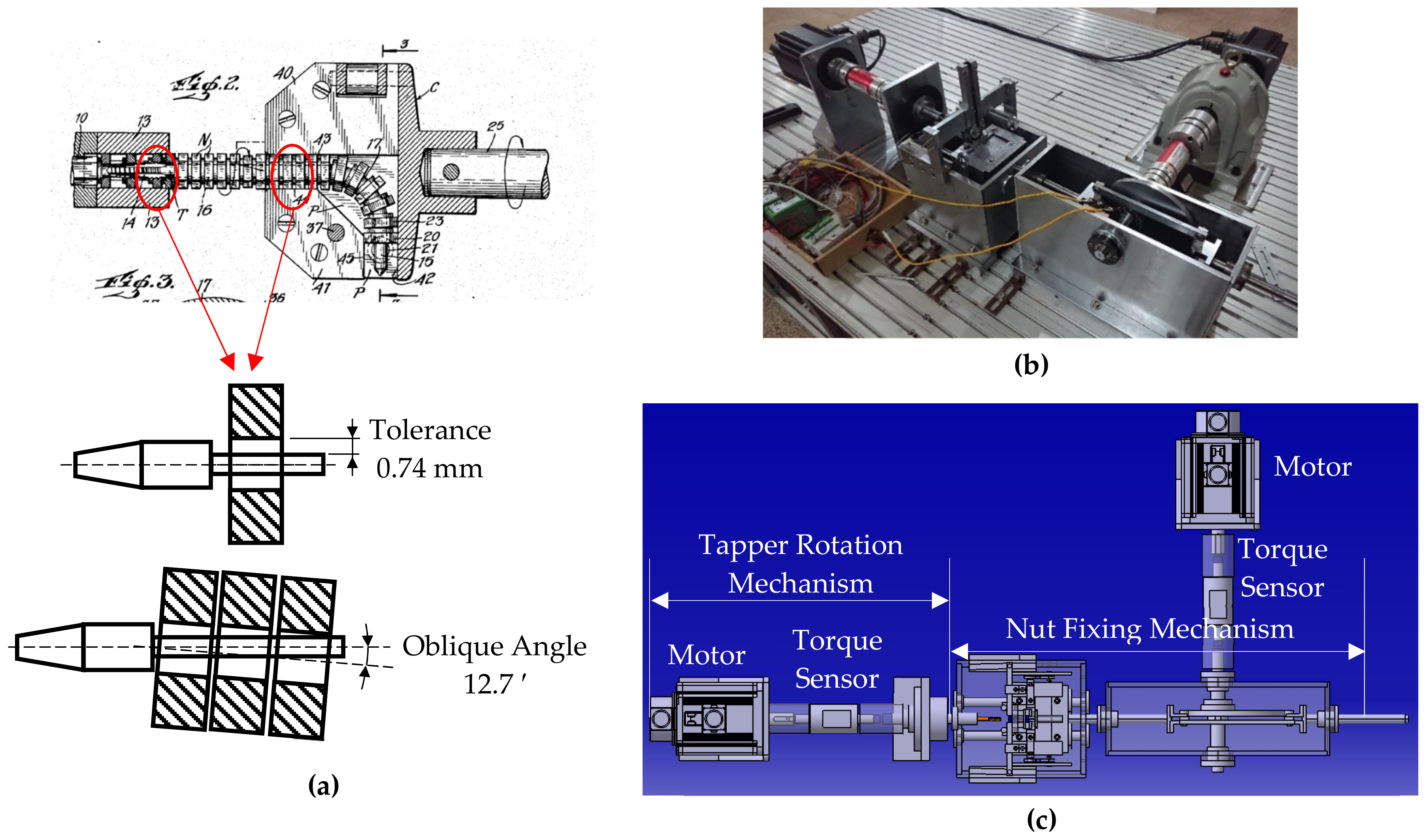
2. Design of a Fixed Tapping Machine for High Precision Tapping

Conventional floating tapping machines are suitable for high-speed production. As shown in Figure 1a for floating tapping, the back-end sleeve drives the tap to rotate continuously and the nut rotation is limited. Since the nut can move forward as the tap rotates and moves across the tap shank, continuous tapping can be achieved. Also, a series of tapped nuts on the tap shank can support tap rotation. Due to the gap between the shank and the hole of the nut, it is difficult to maintain the nut quality using floating tapping. For example, if a M8 × 1.25 nut with a hole size of ϕ 6.84 mm is to be threaded by a tap with a shank having a diameter of ϕ 6.1 mm and length of 200 mm, there is a gap of 0.74 mm between the nut and the tap. Thus, the shank can incline 12.7 arc minutes in the whole row of nuts which can lead to an enlarged tapped hole during the tapping process. Additionally, when the tap rotates, the rigidity of a tap with a long shank will become insufficient. Therefore, it will make the tapped threads misaligned. In such a case, for an M8 tap the torsional deformation is up to 6.2° and may cause deformation of the tapped thread. In addition, when the nut enters the thread of the tap, the shank will shake and affect the tapping precision. Moreover, since the tap and shank are welded together, high-precision welding must be conducted to avoid weld misalignment between the tap and its shank.
Another type of tapping machine is called the reciprocating tapping machine. In the tapping process, the tap moves forward and back in tapping a nut. This requires high-precision control of rotation and linear movement. During the tapping process, the tap often passes completely through the nut. When the tap moves back, the nut may be re-tapped, damaging the thread. Additionally, during the forward and back tapping steps, if the tapping speed is not the same as the rotation speed, partial threads will be produced. Reciprocating tapping machines are suitable for producing large threads in small batches with low production speeds. In this study, based on the concept design [27], a fixed tapping machine was built to achieve high-precision tapping with a highly rigid machine structure.

2.1. Design of the Fixed Tapping Machine

As shown in Figure 1b, the fixed machine has a tap clamp to hold the tap without welding. It has high torsional rigidity when the tap rotates; thus, it can produce high quality internal threads and is suitable for mass production. During the tapping process, the nut holding mold on the nut fixing mechanism limits the nut rotation, and the nut moves forward and back based on the forward and reverse rotations of the tap. This improves the rigidity of the tap clamp so that the tap can avoid shaking while rotating. Using the fixed tapping machine can increase the nut precision in producing threads and remove the problem that floating tapping machines cannot hold the tap stably. Additionally, without using a clamp to fix the nut, the machine uses the mold to limit the nut rotation. In the tapping process, the rotation drives the nut to move, and the drive mechanism drives the mold to move forward and back through the tap. Hence, the machine does not require precision control. This design can make the rotatory motion of the tap independent from the linear motion of the nut and facilitate the center line alignment of the nut and tap.
In consideration of a rigid tapping design, the blanking nut hole and six-axis concentricity of the mold must be concerned with enabling the high-rigidity mechanism to improve precision, stability, cutting speed, and production speed. The tapping machine with a torque sensor made by KTR company is used in this study, as shown in Figure 1c. The recommended cutting speed for alloy steel AISI-4140 nuts is from 5 to 8 m/min, and the maximum tapping torque is from 3.77 to 4.56 Nm [15]. We used a speed of 23 m/min to form threads for 750 nuts. The maximum tapping torque was 4.36 Nm, with a variation of 0.43 Nm and a coefficient of variation of 9.87%. The test results indicated that the equipment can produce relatively stable JIS I (first class) precision threads and that the fixed tapping machine had sufficient rigidity even though the cutting speed was increased by a factor of >2. Table 1 presents the differences of characteristics among floating, reciprocating, and fixed tapping machines.

2.2. Design of the Fixed Tapping Machine

The nut tapping procedure can be divided into five processes: feeding, tapping, reversing, retracting, and discharging. Figure 2 presents a schematic of each process. In the feeding process, the nut is pushed to the tap after unloading, and only the tap rotation creates torque. In the tapping process, the nut enters the tap and starts cutting, removing chips, and bottoming tapping. In the reversing process, the nut remains on the last cutting edge of the tap, and the tap rotates in the reverse direction. In the retracting process, the nut exits the tap. Because there is no cutting edge in the reverse direction of the tap, the torque is created by the friction between the nut and tapped threads. In the discharging process, the nut moves away from the tap, and the untapped nut pushes the tapped nut forward.
In this study, we used torque to monitor the quality of internal threads and used differential geometry to calculate the material removal rate during the relative movement of nuts and taps. We performed experiments on small batches of nuts of certain material nature and cutting speed to determine the tapping torque and establish the upper and lower bounds for thread quality monitoring. In tapping process II, when the torque was not within the bounds range, we checked the thread quality, forged-nut precision, and tap wear. We also monitored the torque in other stages to ensure the stability of the tapping machine.

3. Calculation of Material Removal Rate

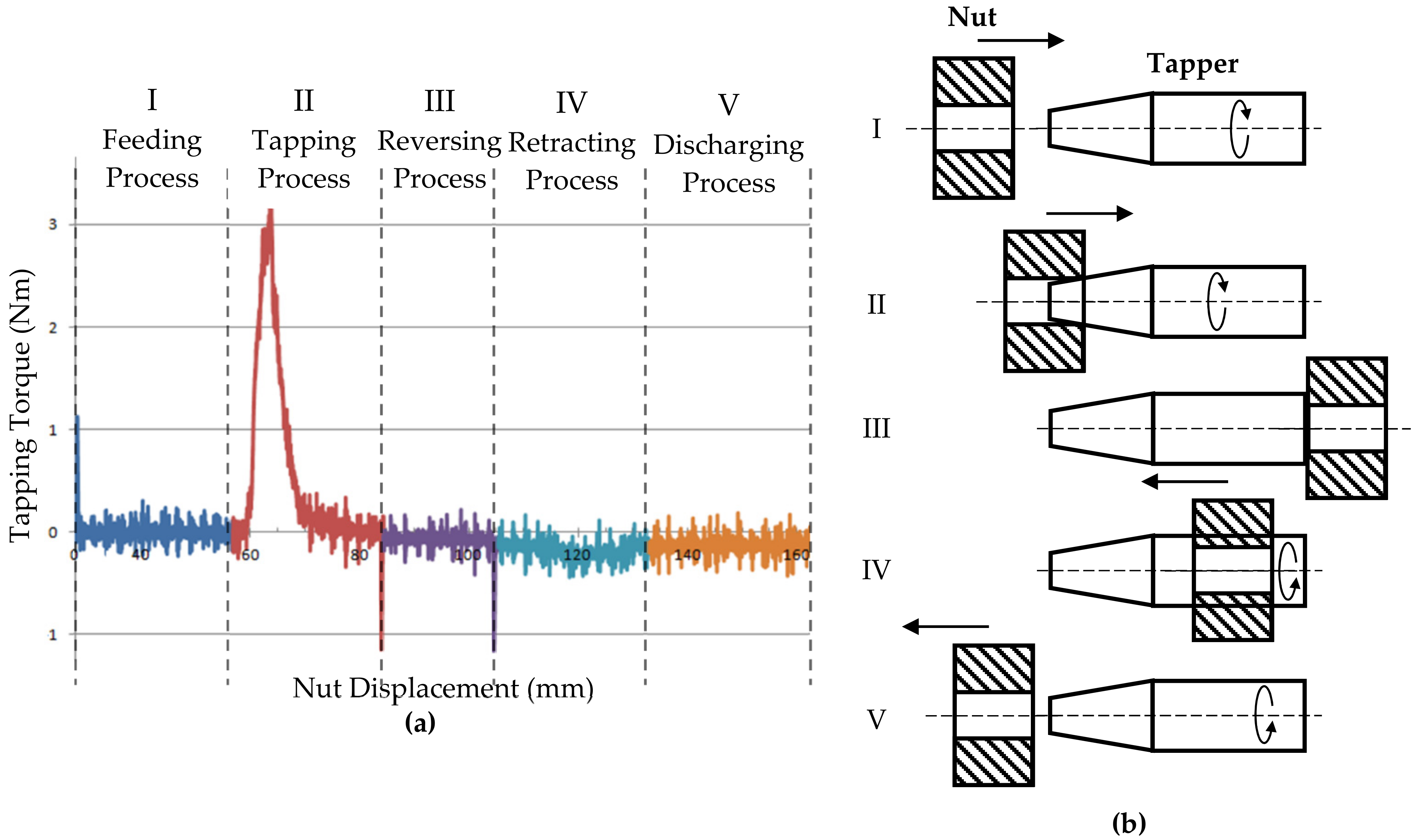
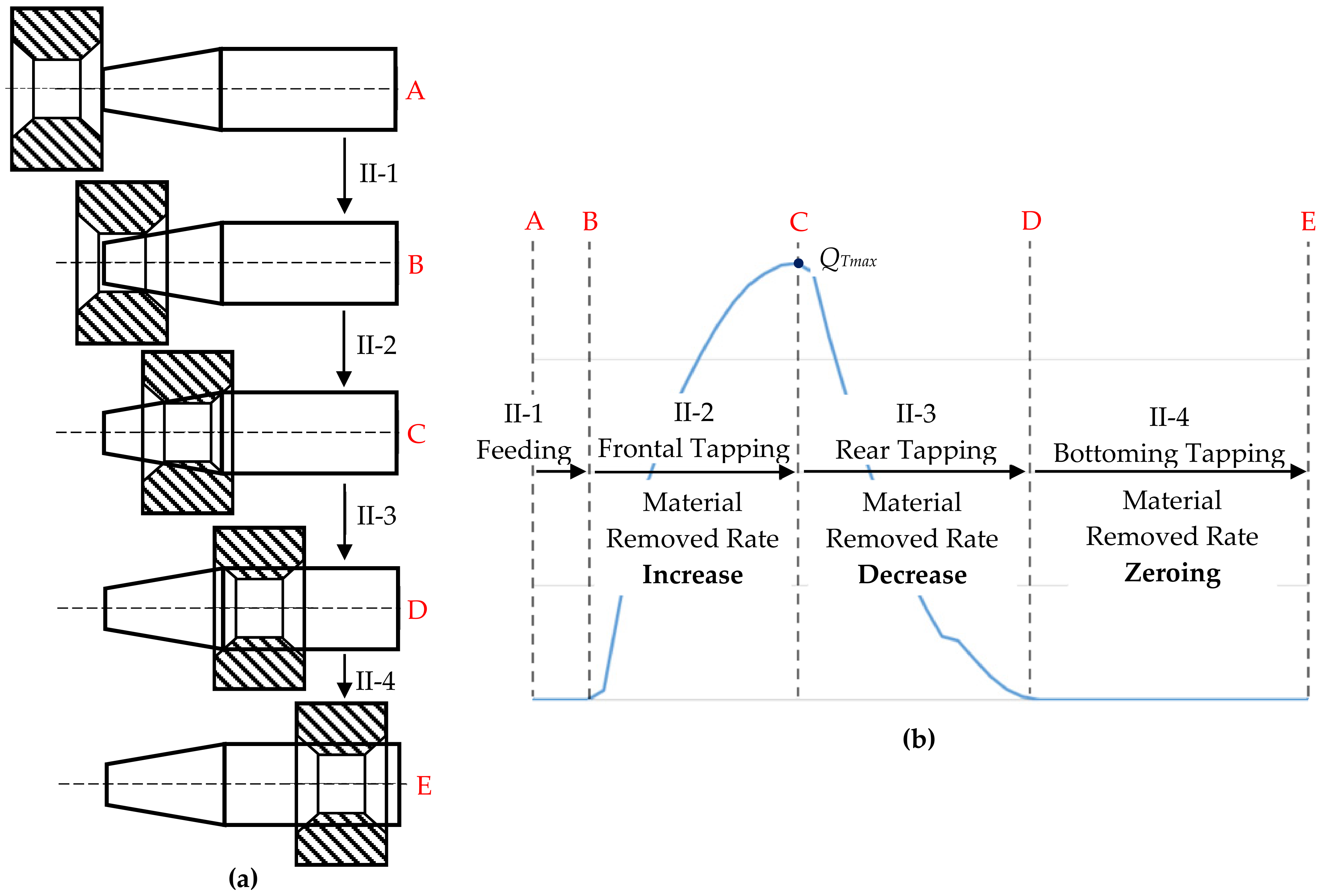
3.1. Material Removal Rate Curve

In this study, the number of grooves, taper angle, and taper length of the tap, and the thickness, hole diameter, and internal chamfer of the blanking nut were considered, as shown in Figure 3a,b. The material removal rate was calculated to establish the cutting stage for tapping process II shown in Figure 2a. We divided the cutting stage into four stages, as shown in Figure 4a. From position A to B, the nut and tap overlap, and the internal chamfer of the nut does not touch the taper; thus, there is no cutting. This is the feeding area in tapping process II-1. From position B to C, the hole of the nut touches the tap; thus, cutting occurs and the material removal amount increases. This is the front cutting area in tapping process II-2. From position C to D, the nut starts to enter the bottoming tapper area; thus, the material removal amount decreases. This is the back cutting area in tapping process II-3. Position D to E is the tapping range without cutting. The variation in the material removal rate in the tapping stage was calculated according to these four stages, as shown in Figure 4b.
In this study, the relative positions of the nut and tap were used to calculate the material removal rate. There were nine parameters: the thread pitch (p), thickness (h), forged hole diameter (dH), internal chamfer depth (hc) of a nut, number of grooves (NG), taper length (LT), tap length (L), maximum diameter (Dmax), and minimum diameter (Dmin) of the tap. First, we used the number of grooves and the number of teeth to determine the total number of cutting edges. Then, we calculated the position angle ( θ i ) of cutting edge on tapper.
θ i = ( i     1 )   ·   Δ θ ,
Here, Δ θ represents the groove angle (shown in Figure 3c) as Δ θ = 2 π / N G and i represents the position of the cutting edge i = 1 ~ I o . Note that Io describes the total number of cutting edges for the nut thickness and tap length as I o = [ ( h + L T ) / p ] + 1 .
Calculating the axial movement (zi) at the position of the groove should be
z i = θ i   ·   p   /   2 π ,
Using the axial movement and the position of the cutting edge, calculating the axial movement (xi) of the nut obtained
x i = ( i 1 )   ·   z i ,
Then, we used the axial movement to determine the nut radius (rni) at the cutting position.
r n i = d c   / 2     z i   ·   tan ( π / 3 ) ,   x i     h C                    d H   / 2 ,   h C   <   x i     h     h C    d c / 2     [ x n   ( h h C ) ]   ·   tan ( π / 3 ) ,   h     h C   <   x i     h ,
Here, dc denotes the minimum diameter of the bearing surface of the nut.
Subsequently, we calculated the tap radius at the current position. First, we determined the distance of the cutting edge (xj).
x j = x i     (   j     1 )   ·   z i ,
Here, j describes the position of the cutting edge within the nut thickness area j = 1 ~ J o , and J o represents the number of cutting edges of the nut thickness area J o = ( h / p ) + 2 .
The distance between two neighboring cutting edges determines the radius (Rti) of the cutting edge.
R t i = D m i n   / 2 + x j   ·   tan   α ,   x j     L T            D m a x   / 2 ,   L T   <   x j     L            0 ,   L   <   x j ,
Here, α represents the taper angle as α = tan 1 [ ( D m a x   / 2     D m i n / 2 ) / L T ] .
Subsequently, we calculated the area of the thread occupied by the nut and tap for each intercept. The area of the equilateral triangle of the nut thread is given as
A n u t = a   ·   h / 2 = 1 2 · 2   ·   h n u t tan π / 3 ·   h n u t = h n u t 2 tan π / 3 ,
where h n u t represents the height of the nut thread as h n u t = D m a x   /   2 -   r n i . The area of the equilateral triangle of the tap thread is given as
A T = a   ·   h / 2 = 1 2 · 2   ·   h T tan π / 3 ·   h T = h T 2 tan π / 3 ,
where h T represents the height of the tap thread h T = D m a x / 2     R t i . Therefore, the area of the nut removed by the tap (the cutting area of a single pitch) is
A i = A n u t   -   A T = ( D m a x / 2   r n i ) 2 tan ( π / 3 )     ( D m a x / 2   r t i ) 2 tan ( π / 3 ) ,
As for the cutting amount Δ A i , it can be found by subtracting the cutting area of the previous tooth from the cutting area of the current tooth as
Δ A i = A i     A i 1 ,
Therefore, when i was calculated for all the cutting edges, we can determine the cutting amount of each pitch at each cutting edge. Assuming that the cutting areas (zj) of the cutting edges within the nut thickness during the movement of the nut, we can determine the total cutting area (CAj) of each feeding nut as
C A j = z i = z m i n z m a x Δ A i ,
Note that the nut thickness range is z j     [   z m i n ,   z m a x ) , where z m a x = z i , z m i n = z m a x     h .
Finally, we used the total cutting area of each feeding nut (CAj), cutting speed (vc), and metal density (ρ) to determine the material removal amount ( Q T ) as
Q T = C A j   ·   v c   ·   ρ   ·   10 3 ,
Note that the units of Q T , CAj, v c , and ρ are g/min, mm2, m/min, and g/mm3, respectively.
As a result, the material removal rate ( Q T ) divided by the maximum material removal rate ( Q T m a x ) is the dimensionless ratio ( q T ) as
q T = Q T   /   Q T m a x ,

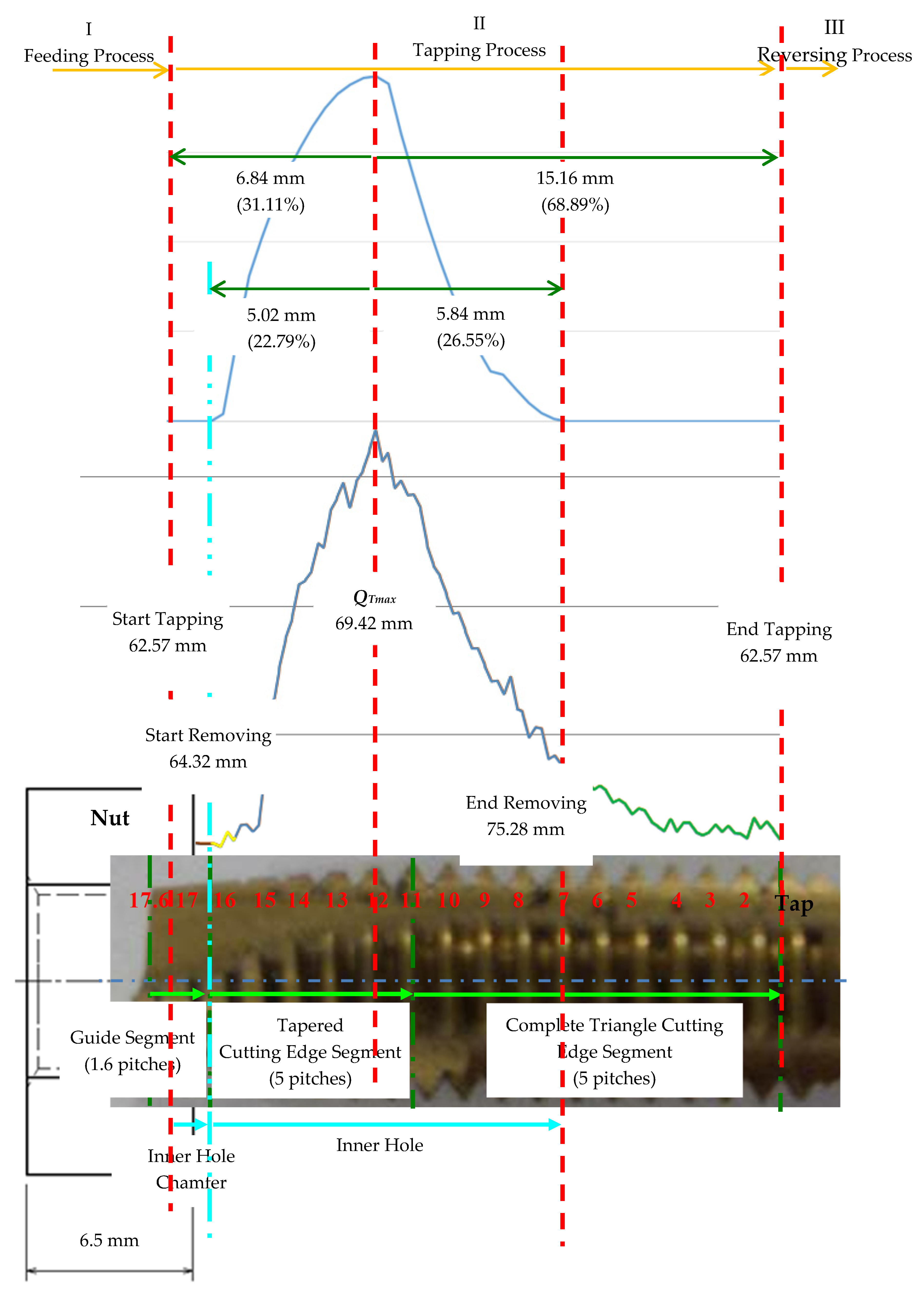
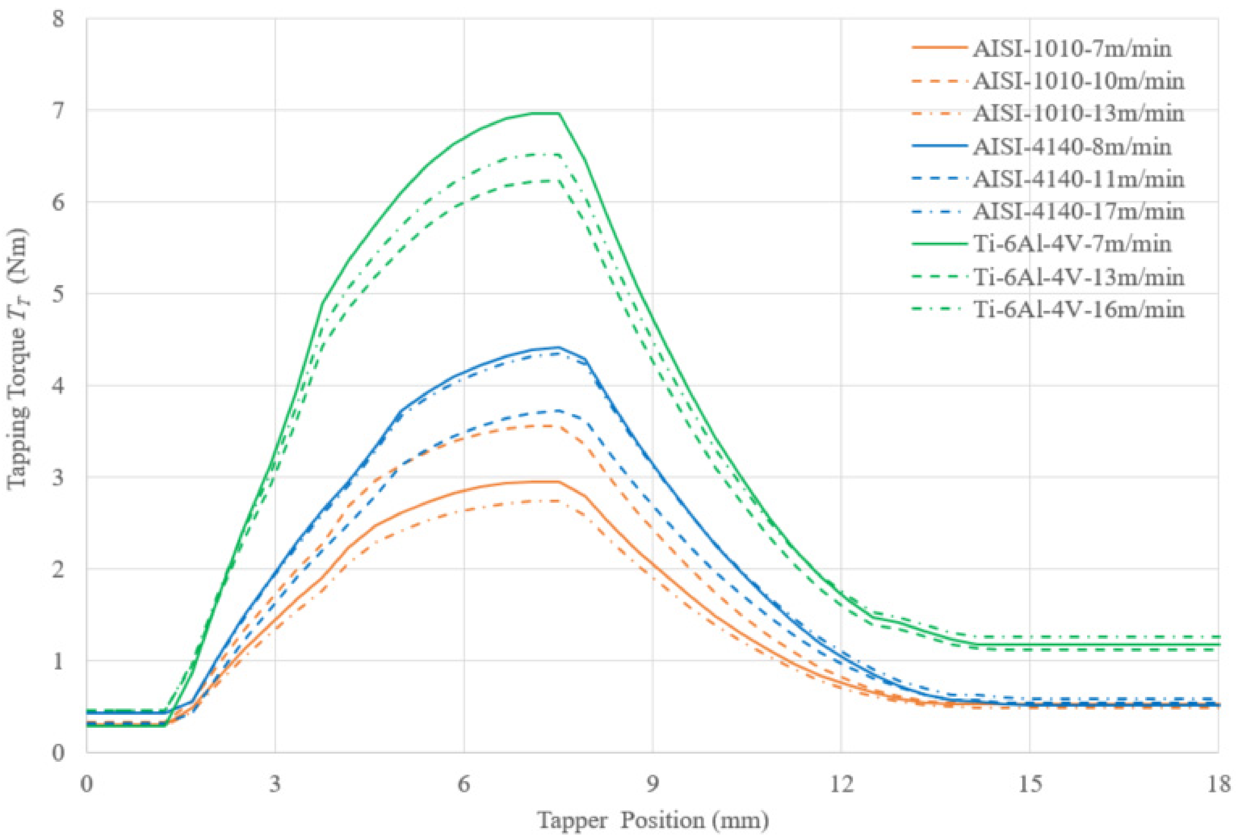
3.2. Observation of Material Removal Rate Curve and Tapping Torque

Figure 5 shows the comparison of the material removal rate curve and the measured tapping torque. In the frontal tapping stage, the nut was cut by the tap without the full teeth area; thus, the material removal rate increased. In the rear tapping stage, the nut entered the tapping range with full teeth; thus, the material removal rate decreased. The curves of the material removal rate and the measured torque have the same geometric feature.

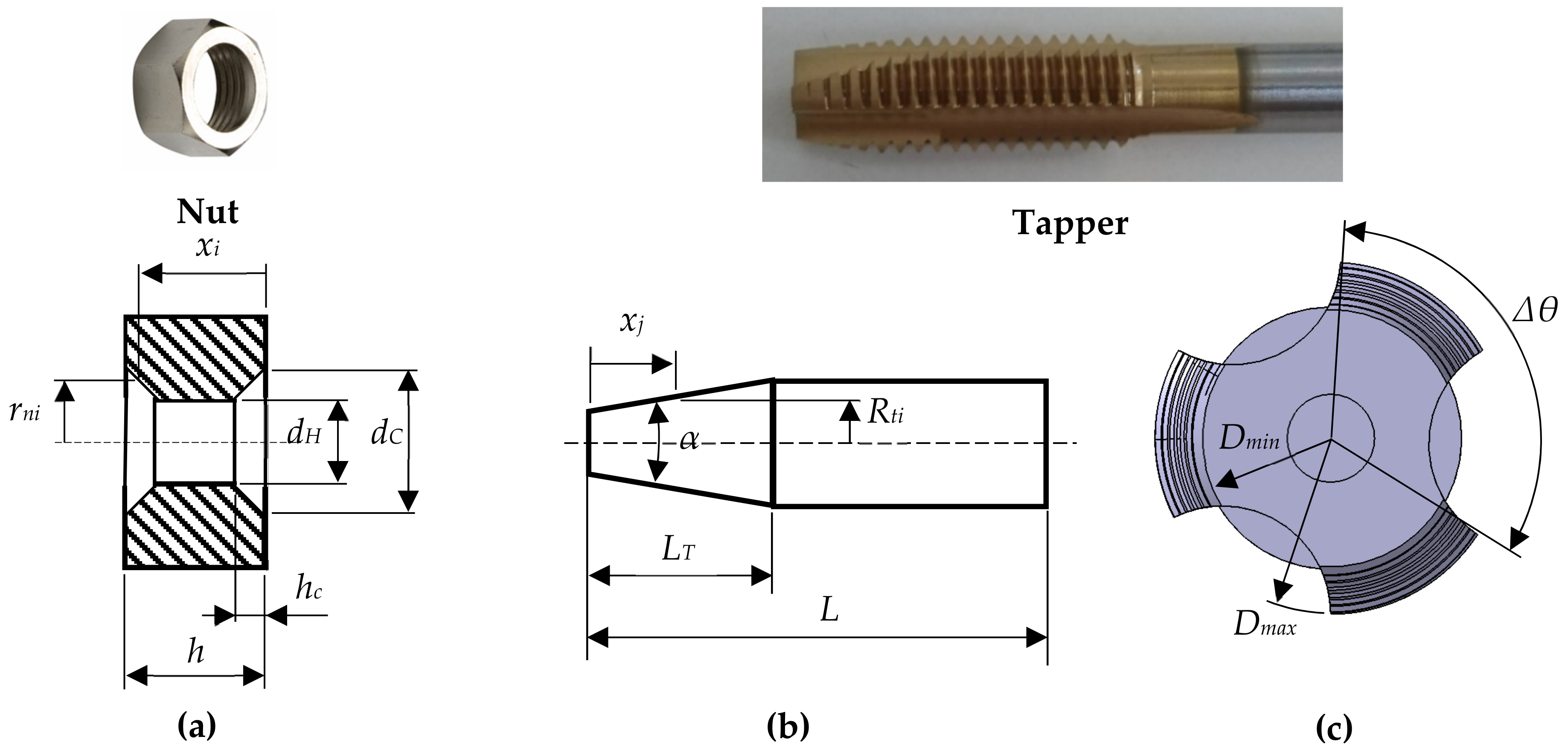
3.3. Effects of Geometric Parameters of Nuts and Taps on Material Removal Rate

The hole size of a blanking nut is the main factor affecting the precision of nut threads; thus, we used different hole sizes and analyzed their effects on material removal amounts. The class of threads is mainly influenced by the hole size. The nut chamfer and the taper length of the tap can affect the maximum tapping torque and its position. In this study, M8 nuts were used as a size example to analyze the effects of the hole size, chamfer angle, and taper length on the tapping process. The parameters of the nuts are presented in Table 2.

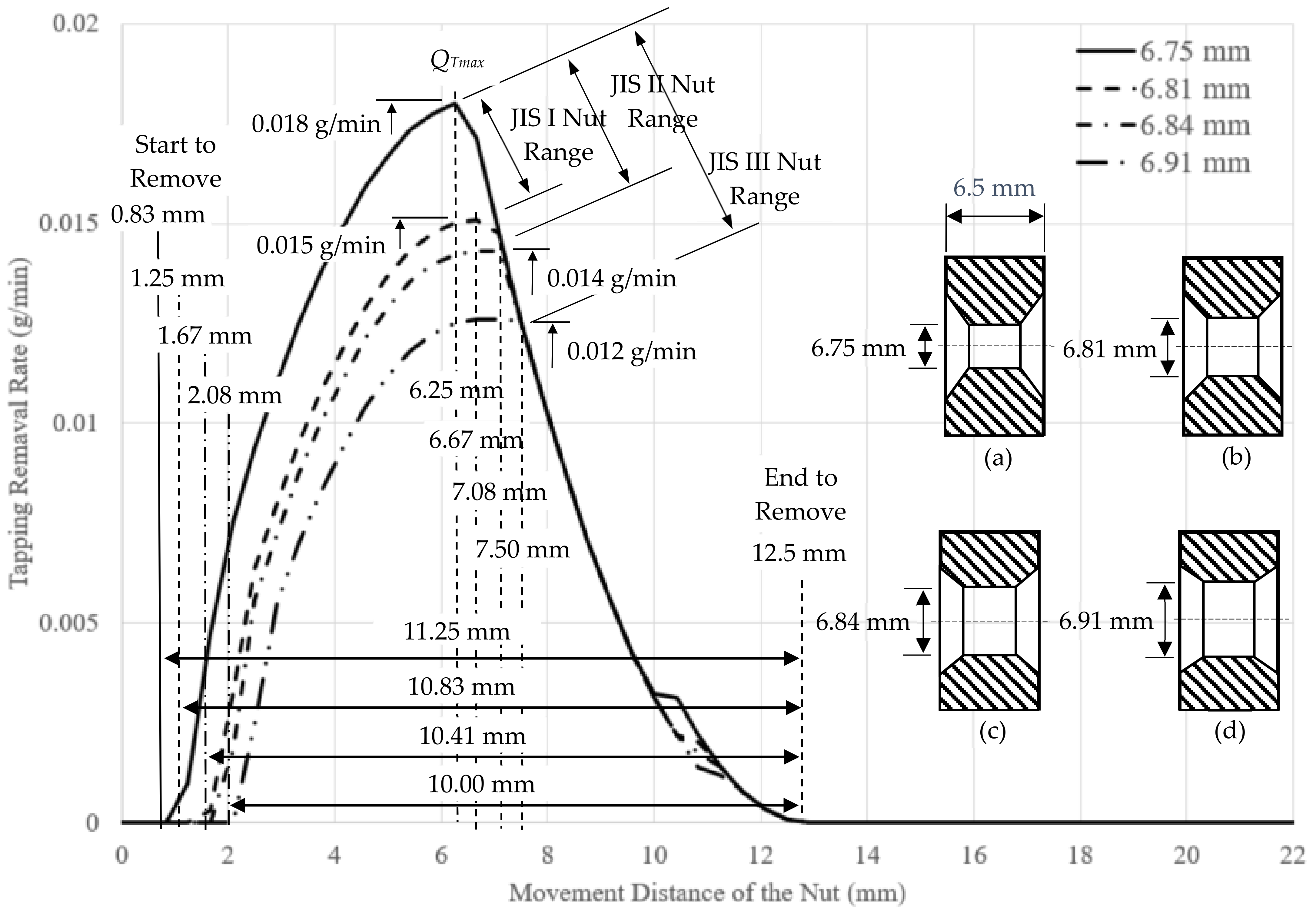
3.3.1. Influence of Hole Size of Nuts

According to the tapping manual [15], the recommended hole size for JIS I is between 6.75 and 6.81 mm, the recommended hole size for JIS II is between 6.75 and 6.84 mm, and the recommended hole size for JIS III is between 6.75 and 6.91 mm. In this observation here, the nut and tap parameters listed in Table 2 were used to compute the material removal amount given in Equation (12) for different hole sizes of 6.75, 6.81, 6.84, and 6.91 mm (dH). The results are shown in Figure 6. We can see that the four tapping ranges and the chamfer depths are identical; thus, the four end points of the material removal amounts are at the same point. However, because the hole size is different, the starting point of the nut touching the tap is different. For a larger hole, the nut touches the tap more slowly, the tapping starts later, and the material amount is smaller. Because we used the same tap for tapping these four different holes, the four calculated material removal amounts in the rear tapping range were about the same.
Observing the computer maximum material removal amount for different hole sizes, as shown in Figure 6, we can see that the nut with a hole size of 6.75 mm has the maximum material removal amount of 0.0180 g/min. Since the hole size of 6.81 mm is the upper limit of a JIS I nut, the maximum material removal amount was reduced by approximately 16.24%, as shown in Figure 6. Hence, if the change of the material removal amount in the tapping process was <16.24%, the nut can be deemed as a JIS I nut. In a similar way, the hole sizes corresponding upper limits of JIS II and JIS III nuts, their maximum material removal amounts were reduced by about 20.54% and 30.13%, respectively. Given a JIS class blanking nut, if the change rate of the material removal amount is over the calculated limit, the precision of the tapped threads will become worse.
Taking a glance at Figure 6 for a larger nut hole, we can find that the cutting started later. Also, a higher precision blanking nut has a narrower nut hole range. Therefore, the approaching distance just before tapping can be used for monitoring.

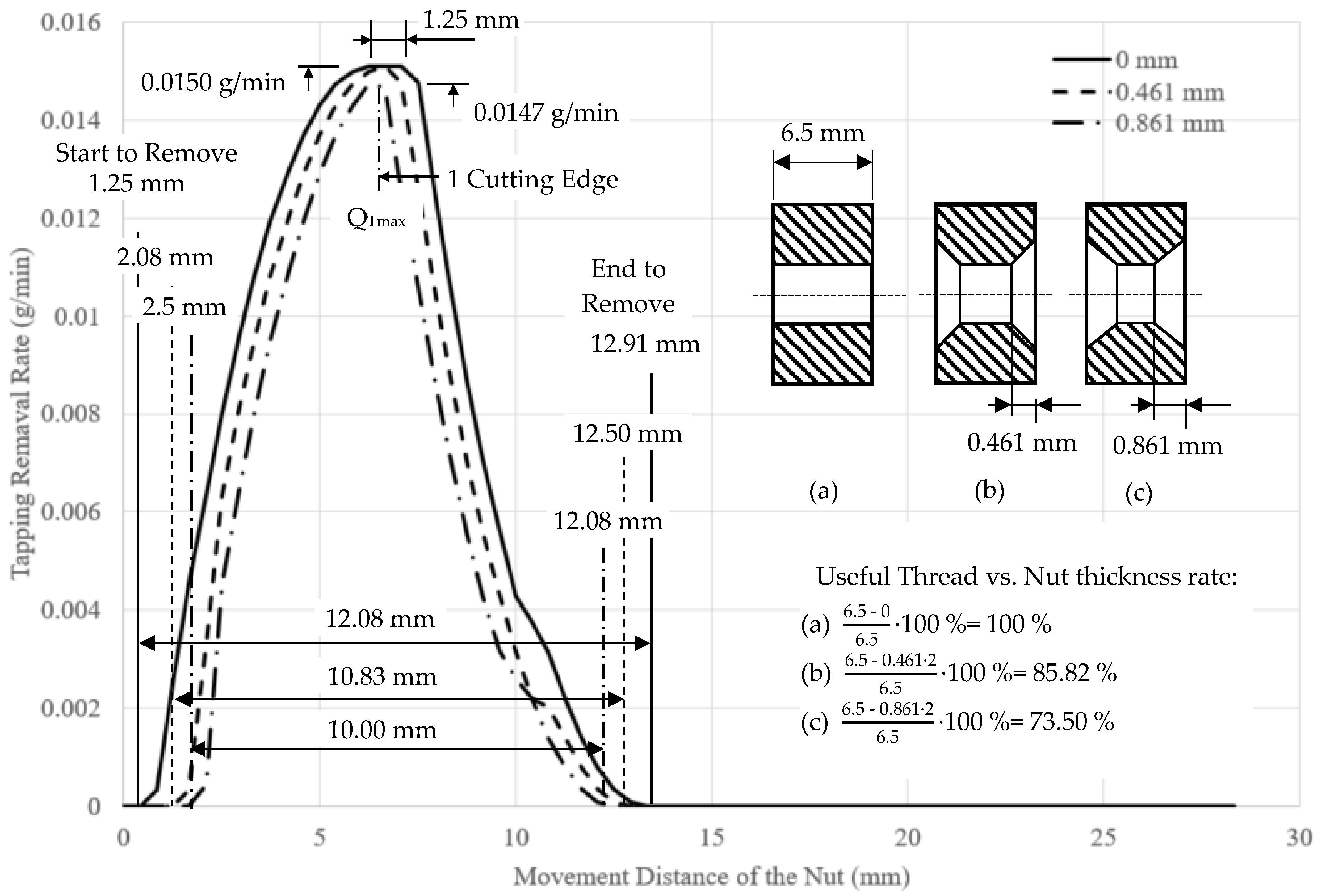
3.3.2. Influence of Chamfer Depth of Nuts

In tapping processes, the tap is guided by the nut chamfer. Usually, the effective threads are >80% of the thickness of the nut. Since during the process of blanking nuts often has the problems of a deep punch and/or a large punch force, these can cause an excessive or abnormal chamfer depth which can affect the material removal amount. In this observation, we performed the analysis by fixing the hole size of the nut and the tap size as well as setting the chamfer depth to 0, 0.461, and 0.861 mm. The results shown in Figure 7 indicate that a larger chamfer angle corresponded to a smaller cutting zone and tapping started more slowly and ended faster.
In the tapping process, a deeper chamfer corresponded to a smaller effective thread area and material removal amount. As shown in Figure 7, when there was no chamfer, the thickness of the effective threads was identical to that of the nut, and the nut movement range accompanying the material removal was 12.08 mm. Similarly, when the chamfer depth was 0.461 mm, the nut movement range accompanying the material removal was reduced to 10.83 mm. As for the chamfer depth of 0.861 mm, the nut movement range accompanying the material removal was reduced to 10 mm. As a result, the nut movement range accompanying the material removal can be used for monitoring whether the nut chamfer is normal or not.

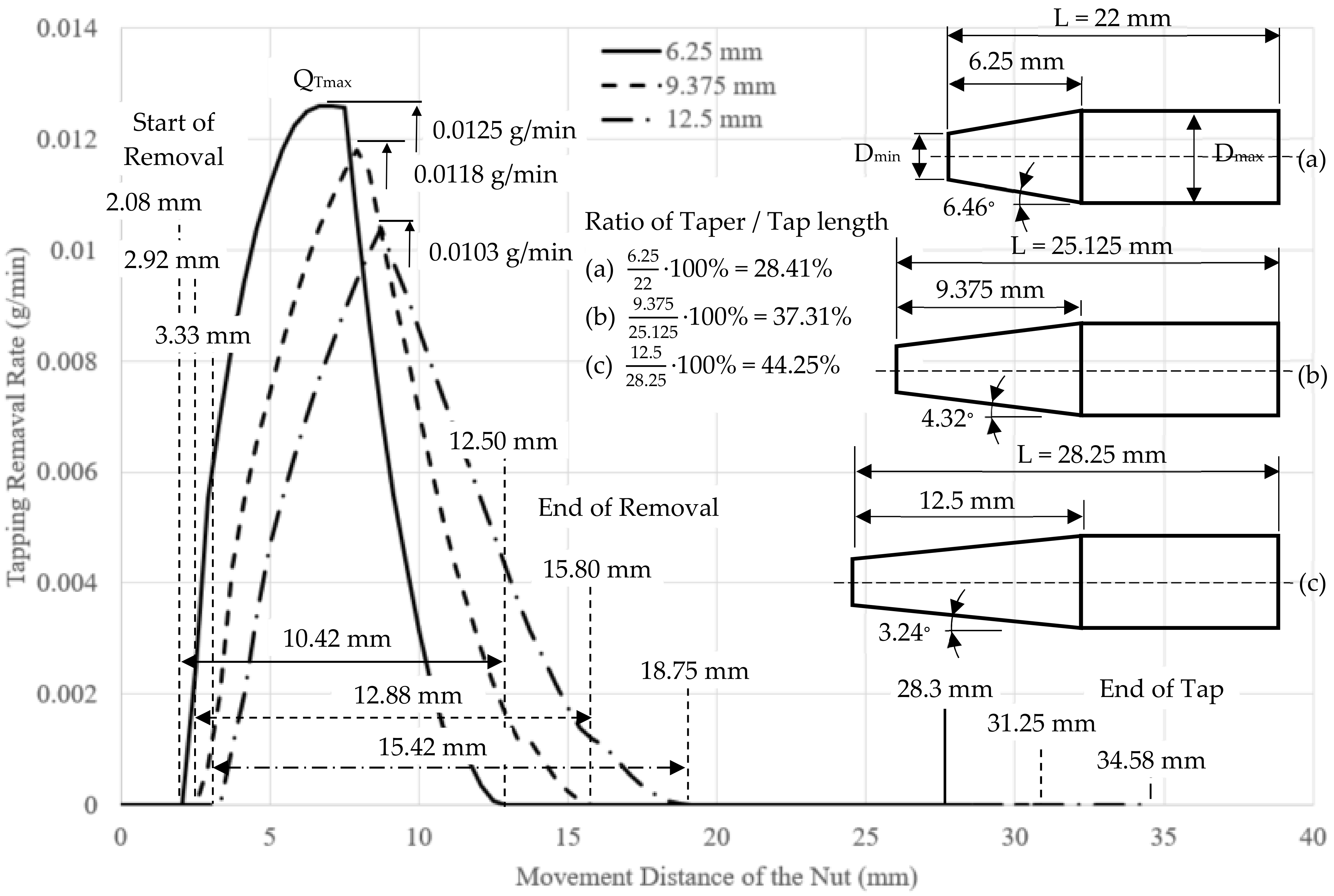
3.3.3. Influence of Taper Angle of Tap

The maximum tapping torque usually occurs near the last two teeth before bottoming tapping starts. In this region, due to the large tapping torque with the maximum material removal amount during tapping, usually severe tap wear also occurs. Therefore, it is necessary to exactly identify the position with the maximum material removal amount. Selecting a proper tap can increase the range accompanying the material removal and reduce the maximum material removal amount so that the tap life can be extended. As shown in Figure 8, when the taper angle decreased, the maximum tapping removal rate decreased. In addition, the tapping start point and end point were delayed, and the cutting area was enlarged.

4. Experiment and Verification

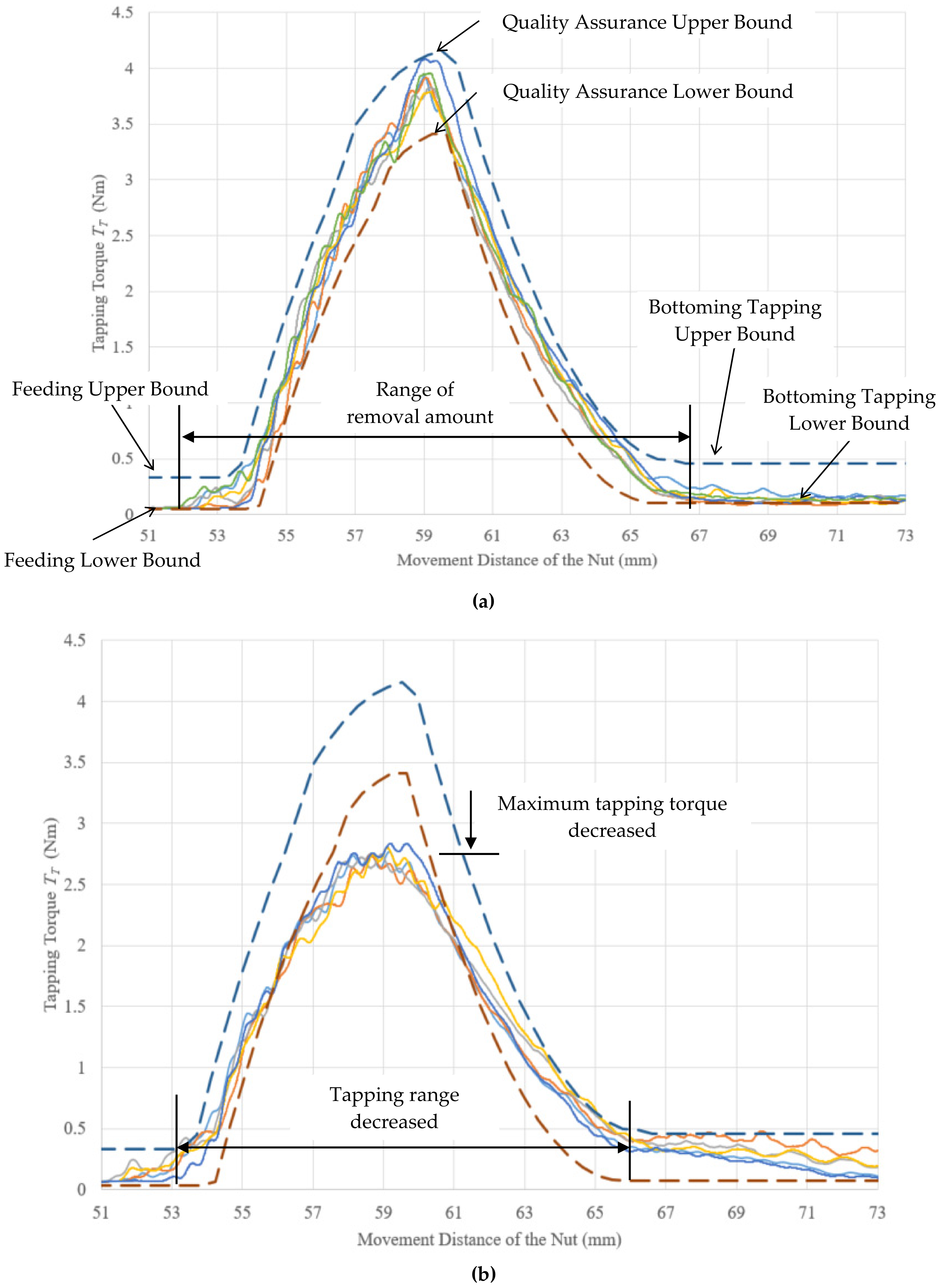
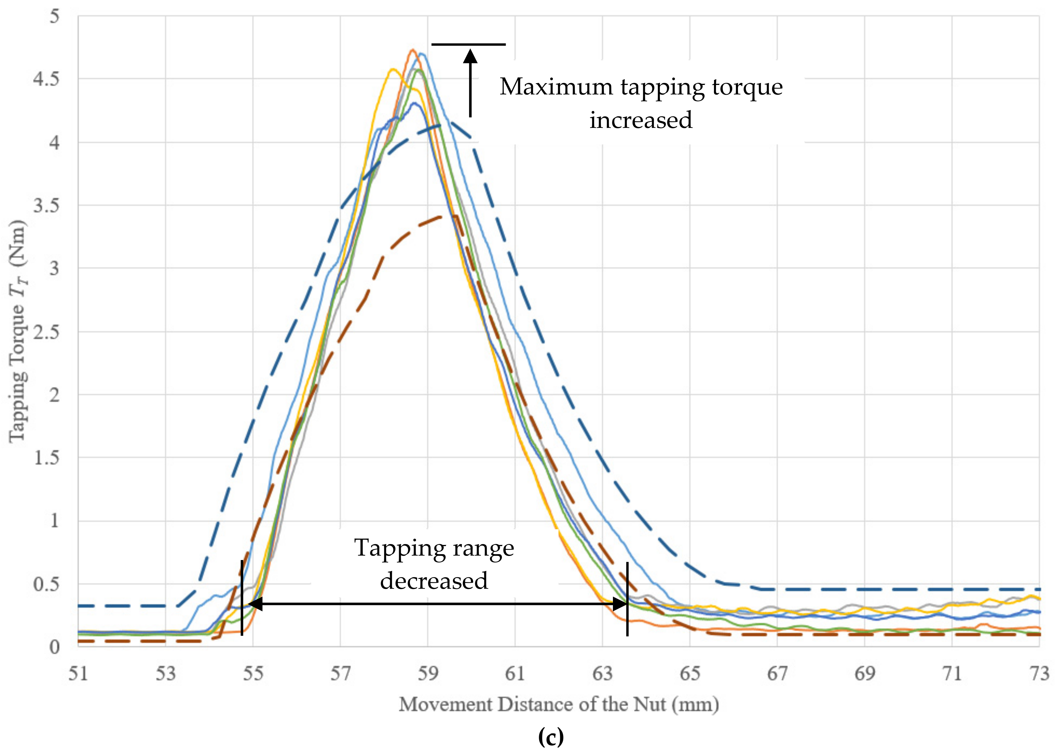
4.1. Establishment of Quality Assurance Module

In this study, 30 nuts that had hole sizes from 6.75 to 6.81 mm, made of AISI-1010, AISI-4140, and Ti-6Al-4V were tapped by different cutting speeds to obtain their corresponding maximum tapping torques. According to the measured data and feature engineering analysis, we obtained the average of maximum tapping torque (   T ¯ m a x ) and its standard deviation for different materials and cutting speeds, as shown in Figure 9. Then, we substituted the maximum tapping torque into the dimensionless material removal rate curve ( q T ) to obtain the tapping torque curve ( T T ) as
T T = q T ·   T ¯ m a x   ,
Note that the units of T T and   T ¯ m a x are Nm. The result of the tapping torque curve for different materials and cutting speeds is shown in Figure 10.

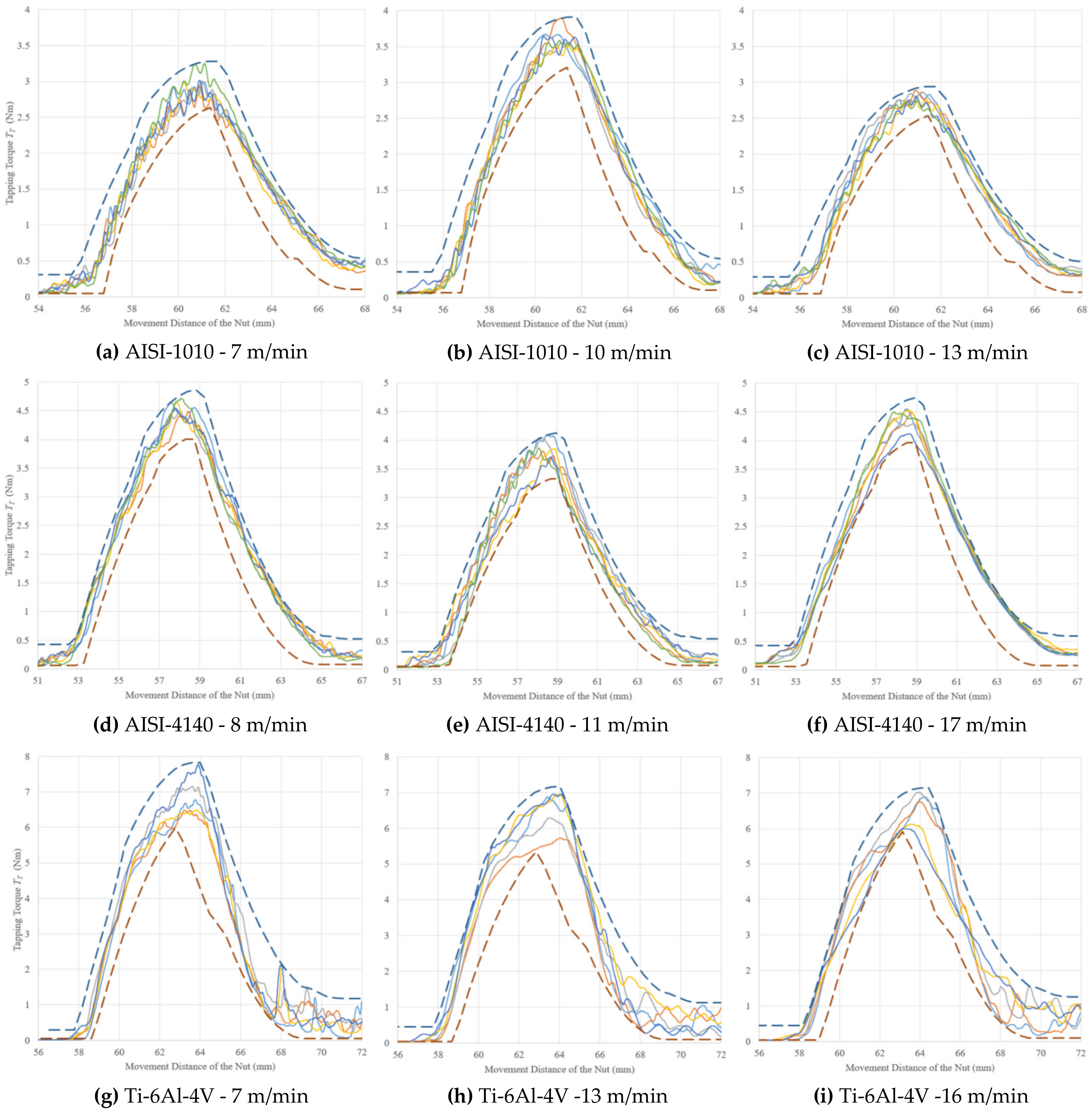
4.2. Experimental Verification

To demonstrate the feasibility of the proposed monitoring scheme for nut tapping quality assurance in real-time, the tapping for AISI-4140 nuts with a cutting speed of 14 m/min was used as an example. We used the aforementioned 30 nuts to determine the upper and lower bounds of the tapping torque, as shown in Figure 10. Using Section 3.1 with Table 3, we could calculate the upper bound ( q T u b ) and lower bound ( q T l b ) of the dimensionless material removal rate curve. The quality assurance range could be obtained as
T q a r     q T l b   ·   (   T ¯ m a x   1 N i N (   T m a x i     T ¯ m a x   ) )   ,   q T u b   ·   (   T ¯ m a x + 1 N i N (   T m a x i     T ¯ m a x   ) ) ,
where, N denotes the number of tapping tests and T maxi is the maximum tapping torque of each test. The units of T maxi and T qar are Nm.
Then, another 200 nuts with hole sizes from 6.75 to 6.81 mm were tapped. As shown in Figure 11a, the results indicate that the tapping torques of the 200 nuts were within the quality assurance range and match the nut quality classification of JIS I. Then, another 10 nuts with hole sizes from 6.81 to 6.85 mm were tapped. The torques were below the lower bound of the quality assurance range, and all the resulting nuts belonged to JIS II classification, as shown in Figure 11b. Since the maximum diameter of the tap was worn down after many tapping processes, the tapping range decreased. As the cutting angle of each edge increased, the maximum tapping torque increased too, as shown in Figure 11c.
To demonstrate the feasibility of the proposed monitoring scheme for nut tapping quality assurance in real-time, three different nut materials (AISI-1010, AISI-4140, and Ti-6Al-4V) and three tap sizes were used, as shown in Table 3. We tested 1000 nuts and monitored the tapping torques with the quality assurance range established by using the aforementioned method. The torques of the 1000 nuts were within the range corresponding to classification of JIS I. For simplicity, we plotted five tapping torques for each nut materials at a fixed tapping speed, as shown Figure 12a–i. The figures indicated that the tapping nuts for the AISI-1010 and AISI-4140 were relatively stable and each nut material had a relatively narrow torque range. The Ti-6Al-4V nuts were tapped with more difficultly and had a wider torque range. The yield strength of the Ti-6Al-4V nuts was 880 MPa, which is higher than those of the AISI-1010 and AISI-4140 nuts (365 and 675 MPa, respectively), and the Ti-6Al-4V nuts also had a larger tapping torque.

5. Discussion and Analysis

  • Effects of blanking nuts and tap parameters on material removal rate
The analysis of the material removal rate indicated that a hole size between 6.75 and 6.91 mm, thickness, chamfer depth between 0 and 0.861 mm of the nut, a taper angle between 3.24° and 6.46°, and the taper length affected the tapping torque, as shown in Figure 6, Figure 7 and Figure 8. When the hole size increases, the range of the material removal rate narrows, and the maximum material removal rate decreases. With an increase in the chamfer depth, the range of the material removal rate decreased, but its influence on the maximum material removal rate was insignificant.
2.
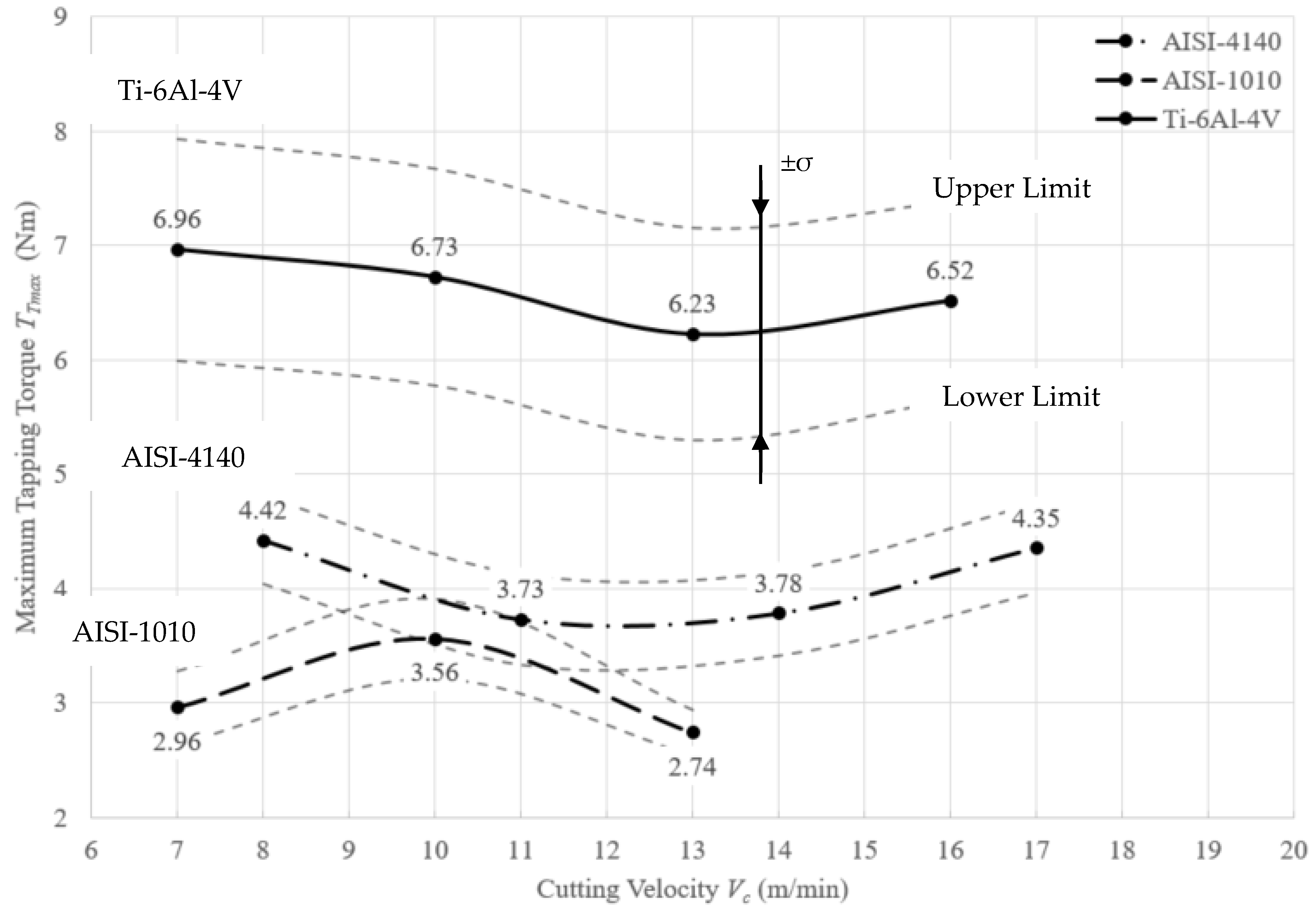
Establishing a nut quality assurance range to monitor thread quality and test three different materials
In this study, nuts made from different materials, AISI-1010, AISI-4140, and Ti-6Al-4V, were used and 1000 nuts in each material were tested. The quality assurance range with different cutting speed were established by using the aforementioned method. The torques of the 1000 nuts were within the range corresponding to the classification of JIS I, as shown Figure 12a–i.
3.
Influence of blanking nuts on tap life
Generally, an increase in the tapping speed may cause fast tool wear. When the maximum tapping torque gradually increases or the tapping range accompanying the material removal decreases, the maximum diameter of the tap decreases due to wear and/or the cutting angle of each edge increases, as shown Figure 11.
4.
Machine health monitoring
The stability of the machine is the most important factor in thread quality monitoring. It is also important to control the rigidity of the tap and the concentricity of the blanking nut. To guarantee the center alignment of the tap, the torque in feeding process I could be used to detect assembly deviations of a tap with its holder during the forward and reverse rotation in the feeding and discharging stages. In the reversing process III, the tap and nut are stopped. So, if the torque is too large, there may be a problem with bearings of the tap holder.

6. Conclusions

In this study, we used a fixed tapping machine in the nut tapping process to ensure the stability of the machine, obtain high quality JIS I internal threads, and monitor the quality of the tapping process and machine health. The quality assurance process of internal threads of nuts mainly includes the following steps:
1. Obtaining the material removal rate curve: Using the hole size, thickness, and chamfer depth of a blanking nut, the taper angle and length of the tap, and the geometric relationship of the relative movement of the nut and tap determined the material removal rate curve. The tapping material removal rates derived in this manuscript are suitable for different nut sizes.
2. Measuring the maximum torque and its variation: Using small batches of nuts to test the material of the nuts, cutting speed, and nature of the tap obtained the maximum tapping torque and its variation.
3. Determining the tapping torque and its upper and lower bounds for thread quality assurance: After confirming the specifications of the tap and nut, the tapping torque curve can be calculated by using the maximum tapping torque and its variation. Then, the quality assurance range can be constructed by the upper and lower bounds of the torque curve according to the tolerance of the blanking nut hole and its chamfer depth. When the tapping torque is within the quality assurance range, the thread quality can be classified as JIS I. When the tapping torque is too small, the nut hole diameter may be too large.
4. Experimental verification: Tapping 1000 nuts verified the quality assurance range for different cutting speeds and materials. All of the torques of the tapped nuts were in the quality assurance range and they matched the nut quality classification of JIS I. The test indicated that the nuts in the JIS II torque range matched the quality classification of JIS II. This quality assurance range can be applied to the automatic high precision tapping process and only requires eight characteristic points (one point from the feeding stage, six points from the tapping stage, and one point from the bottoming tapping stage). The quality assurance range can monitor the precision of internal threads, which can shorten the tapping process of high-quality internal threads and facilitate the digitization of the monitoring process.

Author Contributions

Conceptualization, D.-M.T. and G.-S.H.; methodology, T.-C.L.; software, J.-W.P.; validation, T.-C.L.; formal analysis, M.S.; investigation, J.-W.P. and M.S.; resources, D.-M.T.; data curation, M.S.; writing—original draft preparation, T.-C.L.; writing—review and editing, D.-M.T. and G.-S.H.; supervision, D.-M.T.; project administration, J.-W.P. All authors have read and agreed to the published version of the manuscript.

Funding

This research has been supported by grants 106-2218-E-110-003-MY3, 109-WGEF-A0-800-012, 111-2221-E-110-037, 111-2927-I-110-504 and 111-2218-E-110-004 from the Ministry of Science and Technology, Taiwan and DAAD project ID: 57602200 from the Deutscher Akademischer Austauschdienst, Germany.

Data Availability Statement

The authors attest that all data for this study are included in the paper.

Acknowledgments

The authors wish to acknowledge that Ministry of Science and Technology, Taiwan supported this research. We also thank the anonymous reviewers for providing critical comments and suggestions that improved the manuscript.

Conflicts of Interest

There are no conflict of interest.

References

  1. Nassar, S.A.; Housari, B.A. Study of the Effect of Hole Clearance and Thread Fit on the Self-loosening of Threaded Fasteners. ASME J. Mech. Des. 2007, 129, 586–594. [Google Scholar] [CrossRef]
  2. Jiang, K.; Liu, Z.; Wang, Y.; Tian, Y.; Zhang, C.; Zhang, T. Effects of Different Friction Coefficients on Input Torque Distribution in the Bolt Tightening Process based on the Energy Method. ASME J. Tribol. 2022, 144, 071203. [Google Scholar] [CrossRef]
  3. JIS B 0205-4:2001; ISO General Purpose Metric Screw Threads—Part 4: Basic Dimensions. Japanese Industrial Standard/Japanese Standards Association: Tokyo, Japan, 2001.
  4. ISO 261; ISO General Purpose Metric Screw Threads—General Plan. ISO: Geneva, Switzerland, 1973.
  5. ISO 8839; Mechanical Properties of Fasteners—Bolts, Screws, Studs and Nuts Made of Non-ferrous Metals. ISO: Geneva, Switzerland, 1986.
  6. Lin, E.Y.; Chen, J.C.; Lin, T.C.; Tsay, D.M.; Lien, J.J. Development and Application of Smart Tapping Machine Nut Forming Inspection. In Proceedings of the 16th International Conference on Automation Technology (AUTO), Taipei, Taiwan, 22–24 November 2019. [Google Scholar]
  7. ISO 965-1:1998; ISO General-Purpose Metric Screw Threads—Tolerances—Part 1: Principles and Basic Data. ISO: Geneva, Switzerland, 1998.
  8. Jun, M.G.; Araujo, A.C. Modeling of the Thread Milling Operation in a Combined Thread/Drilling Operation: Thrilling. Int. J. Mach. Tools Manuf. 2014, 87, 16–26. [Google Scholar] [CrossRef]
  9. Kardes, N.; Altintas, Y. Mechanics and Dynamics of the Circular Milling Process. ASME J. Manuf. Sci. Eng. 2007, 129, 21–31. [Google Scholar] [CrossRef]
  10. Anna, C.A.; Guillaume, F.; Gérard, P. Analytical and Experimental Investigations on Thread Milling Forces in Titanium Alloy. Int. J. Mach. Tools Manuf. 2013, 67, 28–34. [Google Scholar]
  11. NORTH-AMERICAN-TOOL-CATALOG. North American Tool 2019. pp. 106–108. Available online: https://www.technitoolinc.com/wp-content/uploads/2021/06/NORTH-AMERICAN-TOOL-CATALOG.pdf (accessed on 18 November 2022).
  12. DRILLING THREADING TOOLS. OSG 2021. pp. 834–845. Available online: https://osg.icata.net/iportal/CatalogViewInterfaceStartUpAction.do?method=startUp&mode=PAGE&catalogId=138540000&pageGroupId=1&volumeID=OSGDCS01&designID=OSGD01 (accessed on 18 November 2022).
  13. Zoltan, D.; Yusuf, A.; Gabor, S. The Effect of Serration on Mechanics and Stability of Milling Cutters. Int. J. Mach. Tools Manuf. 2010, 50, 511–520. [Google Scholar]
  14. Firat, K. An Experimental Study on Cutting Forces in the Threading and the Cut Turning with Coated and Uncoated Grades. ASME J. Manuf. Sci. Eng. 2010, 132, 041012. [Google Scholar]
  15. Gultekin, U.; Ihsan, K. The Effects of Cutting Conditions on the Cutting Torque and Tool Life in the Tapping Process for AISI 304 stainless steel. Mater. Technol. 2016, 50, 275–280. [Google Scholar]
  16. YAMAWA GENERAL CATALOG [JIS,ANSI,DIN]. YAMAWA 2022. pp. 1152–1160. Available online: https://yamawa.meclib.jp/2022-2023_en/book/index.html#target/page_no=1 (accessed on 18 November 2022).
  17. Balázs, T.; Tibor, S. Real-time Determination of Cutting Force Coefficients without Cutting Geometry Restriction. Int. J. Mach. Tool. Manuf. 2011, 51, 871–879. [Google Scholar]
  18. Uhlmann, E.; Holznagel, T.; Clemens, R. Practical Approaches for Acoustic Emission Attenuation Modelling to Enable the Process Monitoring of CFRP. Machining. J. Manuf. Mater. Process. 2022, 6, 118. [Google Scholar] [CrossRef]
  19. Wang, S.-M.; Lee, C.-Y.; Gunawan, H.; Tu, R.-Q. Intelligent Air Cutting Monitoring System for Milling Process. Appl. Sci. 2022, 12, 4137. [Google Scholar] [CrossRef]
  20. Marinescu, I.; Axinte, D. An Automated Monitoring Solution for Avoiding an Increased Number of Surface Anomalies during Milling of Aerospace Alloys. Int. J. Mach. Tool. Manuf. 2011, 51, 349–357. [Google Scholar] [CrossRef]
  21. Asadzadeh, M.Z.; Eiböck, A.; Gänser, H.P.; Klünsner, T.; Mücke, M.; Hanna, L.; Teppernegg, T.; Treichler, M.; Peissl, P.; Czettl, C. Tool damage state condition monitoring in milling processes based on the mechanistic model goodness-of-fit metrics. J. Manuf. Process. 2022, 80, 612–623. [Google Scholar] [CrossRef]
  22. Alexandra, S.; Christopher, S. Indirect Tool Condition Monitoring Using Ensemble Machine Learning Techniques. ASME J. Manuf. Sci. Eng. 2022, 145, 011006. [Google Scholar]
  23. Drouillet, C.; Karandikar, J.; Nath, C.; Journeaux, A.C.; Mansori, M.E.; Kurfess, T. Tool Life Predictions in Milling Using Spindle Power with the Neural Network Technique. J. Manuf. Process. 2016, 22, 161–168. [Google Scholar] [CrossRef]
  24. Uhlmann, E.; Holznagel, T.; Schehl, P.; Bode, Y. Machine Learning of Surface Layer Property Prediction for Milling Operations. J. Manuf. Mater. Process. 2021, 5, 104. [Google Scholar] [CrossRef]
  25. Hakan, D.; Alaattin, K. Experimental Investigation of Hole Quality in Drilling of Additive Manufacturing Ti6Al4V Parts Produced by Hole Features. J. Manuf. Process. 2022, 79, 745–758. [Google Scholar]
  26. Pierre, S.; Florestan, M.; Jean, G. Analytical Study of Maximal Tapping Torque During Forming Screw Process. J. Mater. Process. Technol. 2011, 211, 212–221. [Google Scholar]
  27. Tsay, D.M.; Hwang, G.S.; Lin, T.C.; Chen, W.M. Automatic Nut Tapping Equipment. U.S. Patent No. 11141806 B2, 12 October 2021. [Google Scholar]
  28. Henry, C.T.; Elizabeth, N.J. Nut Tapping Machine. U.S. Patent No. 2356100, 22 May 1943. [Google Scholar]
Figure 1. Two types of tapping machine: (a) Floating tapping machines [28]; (b) Prototype of fixed tapping machine; (c) Structure of fixed tapping machine.
Jmmp 06 00149 g001
Figure 2. Nut tapping process: (a) Tapping torque for each process; (b) Action schematic of each process.
Jmmp 06 00149 g002
Figure 3. Parameters: (a) nut; (b) side view of tapper; (c) front view of tapper.
Jmmp 06 00149 g003
Figure 4. The material removal rate for tapping process II: (a) the relative movement of a nut and its tap; (b) four stages in tapping process II.
Jmmp 06 00149 g004
Figure 5. The characteristics of the material removal rate curve and the measured tapping torque.
Jmmp 06 00149 g005
Figure 6. The tapping removal amount in different hole size: (a) 6.75 mm; (b) 6.81 mm; (c) 6.84 mm; (d) 6.91 mm.
Jmmp 06 00149 g006
Figure 7. The tapping removal amount in different chamfer depth: (a) 0 mm; (b) 0.461 mm; (c) 0.861 mm.
Jmmp 06 00149 g007
Figure 8. The material removal amount in different taper length: (a) 6.25 mm; (b) 9.375 mm; (c) 12.5 mm.
Jmmp 06 00149 g008
Figure 9. Maximum tapping torque for different materials and cutting speeds.
Jmmp 06 00149 g009
Figure 10. Tapping torque curves for different materials and cutting speeds.
Jmmp 06 00149 g010
Figure 11. Quality assurance module for AISI-4140 and 14 m/min: (a) JIS I range; (b) JIS II range; (c) tapper wear. (The solid line is the tapping torque measured by real-time monitoring. The dotted line is the calculation of the quality monitoring curve).
Jmmp 06 00149 g011aJmmp 06 00149 g011b
Figure 12. AISI-1010, AISI-4140, and Ti-6Al-4V in different cutting speeds with quality assurance range.
Jmmp 06 00149 g012
Table 1. The differences among floating, reciprocating, and fixed tapping machines.
Tapping Machine TypeTapping MovementNut MovementCharacteristics
FloatingUnidirectional rotationLinearly forward
  • Insufficient torsional rigidity
  • JIS II thread
  • High production speeds
ReciprocatingBidirectional rotation and Linearly forward and backwardFixed
  • Sufficient torsional rigidity
  • JIS I thread
  • Easily re-tapped
  • Low production speeds
FixedBidirectional rotationLinearly
forward and backward
  • Sufficient torsional rigidity
  • JIS I thread
  • No re-tapped
Table 2. The parameters of the nut and tap.
ParameterSymbolValue
NutPitchp1.25 mm
Thicknessh6.5 mm
Hole diameterdH6.75 mm
Internal chamfer depthhc0.461 mm
TapNumber of groovesNG3
Taper lengthLT6.25 mm
Tap lengthL22 mm
Maximum diameterDmax7.964 mm
Minimum diameterDmin6.547 mm
Table 3. The parameters of tap and nut for three different materials.
Nut materialAISI-1010AISI-4140Ti-6Al-4V
Tap manufacturerNachiP-BeckP-Beck
Number of grooves (nG)333
Tap length (L)222222
Taper length (LT)6.256.756.35
Maximum diameter (Dmax)7.968.158.03
Minimum diameter (Dmin)6.546.476.57
Taper angle (°)6.487.096.55
upper boundlower boundupper boundlower boundupper boundlower bound
Punch hole diameter (dH)6.756.816.756.816.756.81
Internal chamfer depth (hc)0.2610.650.2610.650.2610.65
Density ρ (g/mm3)7.877.854.43
Publisher’s Note: MDPI stays neutral with regard to jurisdictional claims in published maps and institutional affiliations.

