Abstract
Improving scientific knowledge around the manufacturing of nanocomposites is key since their performance spreads across many applications, including those in meso/micro products. Powder metallurgy is a reliable process for producing these materials, but usually, machining postprocessing is required to achieve tight tolerances and quality requirements. When processing these materials, cutting force evolution determines the ability to control the microcutting operation toward the successful surface and part quality generation. This paper investigates cutting force and part quality generation during the micromilling of A356/Al2O3 aluminum nanocomposites produced via powder metallurgy. A set of micromilling experiments were carried out under various process parameters on nanocomposites with different nano-Al2O3 reinforcements (0–12.5 vol.%). The material’s ductility, internal porosity, and lack of interparticle bonding cause the cutting force generation to be irregular when nanoparticle reinforcements were absent or small. Reinforcement ratios higher than 2.5 vol.% strongly affect the cutting process by regularizing the milling force generation but lead to a proportionally increasing average force magnitudes. Hardening due to nano-reinforcement positively affects cutting mechanisms by reducing the plowing tendency of the cutting process, resulting in better surface quality. Therefore, a threshold on the nano-Al2O3 particles’ volumetric loadings enables an optimal design of these composite materials to support their micromachinability.
1. Introduction
Metal matrix composites (MMCs) reinforced with additional hard particles produced via powder metallurgy (PM) show superior properties. The latest advancement of the research area is represented by the use of nanoparticles that allow for better performances with respect to micro reinforcements [1]. However, the production of MMCs is near net shape; parts often require additional machining operations such as drilling, milling, or deburring. PM is difficult for micro feature generation; therefore, micromachining can be considered an enabling technology that further widens the applicability of these innovative materials. In many cases, sintered PM parts are not perfectly dense because sintering cannot completely remove the original porous powder–binder–air structure. This resulting porosity can deteriorate the mechanical properties and machinability [2]. Hard reinforcement particles play a crucial role in the strength of MMCs as an obstacle to the movements of dislocations, creating resistance for deformation and providing strength [3]. This strengthening mechanism carried by the hard particles reduces machinability. Therefore, when machining MMCs, an increased generation of cutting forces is seen with a consequent reduction in tool life due to the excessive cutting temperature [4]. In some cases, contrary results can occur due to the unique nature of the reinforcement particles. For instance, reinforcements such as graphene nanoflakes show a particular lubrication effect and reduce the friction between the tool and the workpiece [5]. On the other hand, reinforcing the PM parts with hard particles to provide desired properties also increases porosity by causing additional surface interactions between metal powders and reinforcement particles [6,7].
Due to the abundance of potential uses and advantageous physical characteristics like low weight and corrosion resistance, aluminum alloys are more often chosen as the matrix material for metallic matrix composites than other materials [4]. However, the machining of aluminum can be challenging, especially for powder metallurgy (PM) parts [8,9]. While reinforcing the aluminum with microparticles, the strength improves, but ductility drops [10]. However, this phenomenon could not be so effective for nanoparticle reinforcement. Nanoparticle reinforcement shows a preserving effect by controlling the decrease in ductility. Nano-Al2O3-reinforced A356 aluminum matrix composites show improved ductility with hardness, yield, and ultimate strength, which is attributable to the uniform distribution of nanoparticles and grain refinement of matrix material [11,12]. It is also known that aluminum alloys containing more than 10% Si has poor machinability. Additionally, alloys containing more than 5% Si do not provide bright surfaces as the bright machined surfaces [13]. Because the microstructure directly influences the micromachining mechanism, the MMCs are not completely homogeneous or isotropic [14]. When the microstructure is refined with finer grains, it is possible to improve the surface quality of the micromachined aluminum alloy components [15]. Other important parameters for the machining MMCs are the particles’ volume fraction and their distribution into the matrix. These features are also directly affected by the design and fabrication processes. If homogenous distribution of particles is achieved in the matrix, the desired physical or mechanical properties can be obtained. Otherwise, MMCs consist of regions with different mechanical and physical properties and cannot behave as isotropic materials. This key feature also has significant effects on the machinability of MMCs, such as excessive temperature, tool breakage/wear, and surface damage. Studies about machining or micromachining of MMCs mostly rely on experimental studies based on the comparison of different matrix materials, particle reinforcement ratios, and tool materials or combinations of them [16]. In addition to the workpiece material properties such as volume fraction of reinforcement particles [16,17], spindle speed and feed rates are also effective parameters on cutting forces when machining micro and nanocomposites [18,19]. During the micromachining of polymeric–metallic composite material used in metal additive manufacturing, a particular interaction between the micro tool cutting edge and the loading particles was discovered [20]. An analytical cutting-force modeling, in particular, was suggested to describe the effects of the cutting-edge radius when cutting composites with various particle diameters. Other authors studied the microcutting of soft metallic materials such as aluminum alloys. Campos et al., for example, presented a mechanistic cutting-force model adapted for the micromilling of an aluminum alloy [21]. They concluded that the cutting speed presented more influence than feed per tooth on the specific force confirmed via the mechanistic model. Liu et al. proposed a method for realizing the ductile regime machining by selecting the cutting parameters to improve the surface qualities of SiCp/Al MMCs [22]. The results indicate that the minimum chip thickness and feed per tooth are heavily affecting the generation of the machined surface by causing a matrix-coating effect or fracture of the particles. Increasing the feed per tooth increases the arithmetic mean of the surface roughness (Sa). In their other work, they pointed out that surface roughness is affected by the feed rate, and this can rely on the plowing effect of the Al matrix and the removal of the particle in a ductile regime [23]. Some studies report that the depth of the cut is also an influencing factor for cutting force, surface roughness, and tool wear [24]. The increasing volume fraction of nano-reinforcement particles raised cutting force magnitudes when SiC nanoparticle-reinforced Mg matrix composites were micromilled [17]. Often, these justifications are attributed to improved strength by adding harder micro and nanoparticles; however, there are also other comments about the machining of MMCs. Teng et al. proved that cutting forces for the machining of pure Mg alloy is larger than that of MMCs reinforced with nano-sized particles [25]. They based this phenomenon on improved ductility due to nanoparticles which provide less force to initiate plastic deformation. They also concluded that finer surface roughness could be generated by nanoparticle reinforcement due to their elastic recovery caused by the increased ductility. Moreover, there are numerical/mechanical modeling and simulation studies on the macro/micromachining of micro/nanocomposites. Pramanik et al. projected a mechanics model to predict cutting forces for aluminum-based SiC/Al2O3 micro-particle-reinforced MMCs [26]. They reported an agreement between predicted and experimental results for the total force generation mechanism based on the chip formation force, the plowing, and the particle fracture force. They also studied the machining behavior of MMCs with the help of finite element modeling simulations [27]. They found that the main reasons for particle fracture and debonding during the machining of MMC are the magnitude and the distribution of stress/strains in the material and the interaction of particles with the tool. They also reported that the feed rate parameter controls surface roughness. Teng et al. proposed a two-dimensional simulation study to simulate the micromachining process of Mg/SiC MMCs with consideration of the cutting-edge radius [28]. Their results showed that the particles restrict the progression of stress within the matrix, resulting in highly strained particle interfaces. Tool wear is also significant for the machining of the MMCs, as the tool will interact directly or indirectly with the reinforcement particles. While machining aluminum MMCs reinforced with microparticles, a build-up edge (BUE) can be formed on the cutting edge via material adherence due to friction, high temperature, and pressure [29]. While BUE formation during machining can cause tool wear by increasing the tool rake angle [30,31], only cutting parameters such as cutting speed, depth of cut, and feed rate can also be factors that increase tool wear [32]. Although several studies have been conducted on the micromilling of Mg matrix nanocomposites, there are still very limited studies about the micromilling of nanoparticle-reinforced aluminum matrix composites (5, 17, 18, and 25). In most studies, researchers focus on interpreting the cutting mechanism by measuring the cutting forces, tool life, and resulting surface characteristics. However, the related effects driven by the quantity of nanoparticle reinforcement are usually not discussed.
This present study wants to fill this lack by investigating the direct effects of nanoparticle reinforcements on the micromilling force and part quality generation in nano-reinforced MMCs. Micromilling experiments were conducted on different samples for a wide range of cutting parameters to understand the links between the cutting parameters setup and the nano reinforcement contained in the parts.
2. Materials and Methods
2.1. Workpiece Materials and Specimen Production
A356/Al2O3 nanocomposite samples with six reinforcement ratios (0–12.5 vol.%) produced via PM were used as workpiece materials for micromilling tests. A356 (LPW Technology Ltd., Runcorn, UK, APS: 46 µm, chemical composition: 7.5 Si (%wt.); 0.7 Mn; 0.4 Mg, 0.2 Fe; 0.2 N; 0.2 O; 0.15 Ti; 0.05 Cu; 0.1 Zn) and Al2O3 powders (Nanografi Inc., Jena, Germany, APS: 20 nm) were mechanically milled for 4 h in Fritsch planetary ball milling device with a single chamber (capacity: 225 mL). After mechanical milling, the powders were cold pressed (600 MPa) to produce green samples. The green samples were sintered at 565 °C for 1 h in a vacuum furnace. A total of six workpieces with different reinforcement ratios were manufactured. The microstructures of MMCs produced via powder metallurgy consist of primary alpha aluminum containing small silicon phases shaped like particles called eutectic structures (Figure 5). The dimensions of each cylindrical sample are 10 mm in diameter and 15 mm in length. Figure 1 represents the manufacturing route of the nanocomposite workpiece samples.
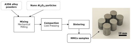
Figure 1.
Flowchart of the production process and the nanocomposite workpiece samples.
2.2. Machines, Tools, and Measurements
Precisa XB200h density measurement kit was used for the density measurement of the A356 alloy and the nanocomposite samples. Hardness tests were carried out on AFFRI VRSD 251 hardness tester. Brinell hardness method was applied to the samples with 31.5 kgf load for 5 s. The average value was calculated from five different measurements on each sample. Kern EVO 5-axis CNC micromachining center was used for the cutting experiments. Sandvik CoroMill Plura solid carbide end milling (R216.32-00530-AE05G 1620) tools with an edge radius of around 10 µm, a diameter of 0.5 mm, and a flute helix angle of 30 deg. were used for micromilling tests. Figure 2 shows the geometric properties of the micromilling tool. Schunk-Tribos clamping device was used as a tool holder.
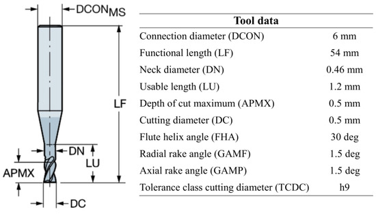
Figure 2.
The geometric properties of the micromilling tool.
Kistler 9317 Type B triaxial dynamometer, National Instruments NI 9234 Sound and Vibration Input Module, and NI 9171 USB DAQ module carrier were used to measure cutting forces. Figure 3 represents the experimental setup with the CNC machine, the force measurement system, and the workpiece fixture setup.
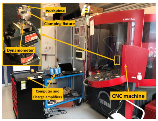
Figure 3.
Experimental setup, machines, and equipment.
2.3. Experimental Plan and Cutting Conditions
For full factorial experimental design, four factors were determined: Al2O3 reinforcement ratio (6 levels also represent the 6 workpiece material), feed/tooth (3 levels), axial depth of cut (2 levels), and radial depth of cut (2 levels). Spindle speed and cutting speed were kept constant at 30,000 rpm and 47 m/min. Table 1 provides the parameters of the design of the experiment. With two replications of each test, a total of 144 tests were executed.

Table 1.
Material and cutting process parameters adopted. Spindle speed: 30,000 rpm. Cutting speed: 47 m/min.
Due to the cylindrical shape of the MMC parts, a milling strategy in which the tool moves from the center to the outer surface was adopted. Face milling was applied to clean the top part surfaces, followed by the cutting tests with the variable conditions listed in Table 1. To generate better control of the cutting, a cylindrical pocket was applied at the center of the workpiece prior to the execution of the main cutting tests. Because of the limited surface area of the workpiece, this experimental study was divided into two sections, including 72 tests (12 for each material) conducted on the first floor using the first tool and 72 tests performed on the second floor using the second tool. After collecting experimental investigations on the first floor, face milling was applied to remove residuals, and the second floor was obtained. Further experiments were carried out on this second floor. Figure 4 shows a representation of the micromilling strategy. The experiments were conducted in random order, trying to prevent the possible effects of all the unmeasured external factors.
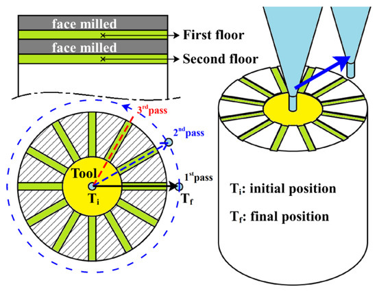
Figure 4.
Schematic representation of the conducted microcutting experiments on the cylindrical MMCs parts. The continuous blue arrow represents the tool trajectory.
2.4. Cutting Force Measurement and Tool Wear Analysis
Cutting forces were measured with an acquisition frequency of 17,067 Hz, but then low pass filtering at 1750 Hz was applied to the raw cutting force data via MATLAB software R2022a to avoid the unwanted effect given by the excitation of the main natural resonance of the dynamometer. The average of the root mean square value of the resultant force signal (rms(Fr)) is therefore computed, whereas the resultant forces (Fr) were calculated from the original triaxial cutting forces (Fx, Fy, and Fz). For each test, the entrance and exit regions of the cutting forces were ignored from the cutting force analysis. Analysis of variance (ANOVA) is applied to evaluate experimental results using Minitab software v21. The effects of four factors (reinforcement, feed per tooth, axial and radial depth of cut) on the response variable (average resultant cutting force) were determined statistically. To analyze the regularity of the cutting forces, the force signal was divided into five portions (not overlapped), and the difference in mean values of these portions of the signal was investigated. The standard deviation of these five portions was evaluated as the regularity of cutting forces during the micromilling of nanocomposites. A block factor was used in the cutting tool unit (one tool unit was used to machine one floor of the material, while the second tool was used for the second floor). The experiments were conducted in random order to prevent or minimize tool wear-related errors.
2.5. Surface Analysis and Burr Measurements
Mahr MarSurf CWM100 hybrid microscope (confocal and white light interferometer) was used with a 10 × NA0.5 lens to scan the roughness and the burrs of the samples. This lens setup was used to have full access to the cutting slots preventing limits due to the focal depth of the microscopes as typical with micromachined slots [33]. Each workpiece was fully scanned, and a circular surface profile for each slot was generated. The surface roughness data were collected in terms of average surface height Sa. SEM and an optical microscope were used for part integrity evaluation.
3. Results
3.1. This Density and Hardness
The composite powders can be considered ductile–brittle (A356-Al2O3) components. During mechanical milling of ductile–brittle components, the ductile metal powder particles are flattened via deformation (ball–powder–ball or ball–powder–wall), while brittle particles are fragmented. These brittle particles tend to be trapped within ductile particles. With further milling, the ductile powder particles are work hardened and refined via crimping/folding [34]. Such microstructural effects were also observed in the microstructures of the samples obtained in this study. Figure 5 shows the microstructures of workpiece materials (after sintering) with different reinforcement ratios subjected to the same mechanical milling route. With higher reinforcement ratios, ductile particles are deformed and refined with smaller and more complex forms. The analysis of the sintered parts conducted prior to cutting them allows us to confirm that the sintered part density decreases along with the nanoparticle reinforcement. In particular, the values of the A356 alloy and nanocomposite reinforced materials resulted as 96.13 ± 0.26 (A356), 96.30 ± 0.36 (2.5% reinforced), 93.93 ± 0.38 (5% reinforced), 90.40 ± 0.49 (7.5% reinforced), 88.74 ± 0.27 (10% reinforced) and 85.78 ± 1.47 (12.5% reinforced). A noticeable drop in density is found for reinforcements higher than 2.5%, and a total reduction of 10.77% is generated by adding 12.5 vol.% nano-Al2O3 reinforcement in the A356 matrix (Figure 5). The minor images in Figure 5, created by filtering the microstructure images by similar thresholds, highlight the pores (black) and their distribution.
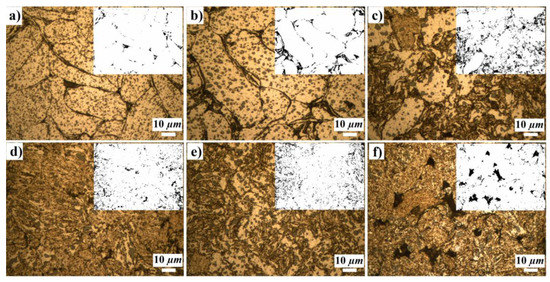
Figure 5.
Microstructures of the workpiece samples prior to cutting, (a) A356 Alloy, (b) A356/2.5 vol.% Al2O3, (c) A356/5 vol.% Al2O3, (d) A356/7.5 vol.% Al2O3, (e) A356/10 vol.% Al2O3, (f) A356/12.5 vol.% Al2O3 nanocomposite sample (The minor images on the upper right represent the pores and their distribution).
The decreased relative density of the sintered parts can be explained using different mechanisms in both the forming and the sintering stages. Regardless of their nano-Al2O3 content, the original powder particles are subjected to plastic deformation and formed in different shapes during mechanical milling. The particles can be repeatedly fractured, and the surface areas of these particles grow with deformation, which produces more voids/pores at the interconnection regions of the particles [34]. The sintering process cannot fill these regions, creating a residual porosity on the sintered parts. It has to be considered that the melting and sintering temperatures of Al2O3 nanoparticles are much higher than that of A356 alloy (almost four times the temperature difference); therefore, it is not possible to achieve the sintering of Al2O3 particles. However, the effect of the nano loading on the sinterability of these materials is very complex, and it is not discussed in the paper as our goal is to address the micromilling machinability only.
When adding the reinforcement, the compressibility of the powder particles becomes more limited. This is because the reinforcement increases the powder particles’ hardness. This hardening effect is caused by the strain hardening mechanism induced via the increased deformation that happens with increased nanoparticle volume fractions. The second mechanism that can be pointed out as a hardening effect is the Orowan mechanism; nanoparticles prevent dislocation movement during deformation and provide better resistance to deformation [6]. The lower powder compressibility, caused by the increased particle hardness, produces a substantially increased number of voids/pores at interconnection regions on the pressed compact. In case the sintering process cannot densify the material enough, the final relative density of the resulting material is affected.
The hardening caused by the nanoparticle reinforcement is quantified by measuring the sintered hardness on the parts. The hardness of the A356 alloy is measured as 41.7 HB, whilst the 12.5 vol.% nano-Al2O3 alloy produced a measurement of 69.3 HB (66.4% of the increase). The hardest parts are, however, represented by the 10% nanocomposite that showed a slightly bigger hardness of 12.5%. This can be due to the agglomeration of nano- Al2O3 particles that could have generated weaker bonding between nanoparticles, affecting their capacity to strengthen the original A356 matrix [11].
3.2. Cutting Mechanisms and Cutting Forces
A356 alloys and A356/2.5 vol.% Al2O3 nanocomposites have a microstructure that clearly consists of bigger and slightly deformed particles (Figure 5a,b). The particle (grain) boundaries are clearly noticeable. This evidence is linked to the presence of surface oxidation of the particles during mechanical milling. For this reason, the grain shows weak interconnection bonding. During the micromilling of A356 alloy and A356/2.5 vol.% Al2O3 nanocomposite, these grains are, in fact, not stable in their positions. When the tool contacts a grain, three different mechanisms can occur. On one side, grain particles could leave their positions because of weak bonding generating a total grain pull off. In other cases, when there is sufficient bonding, the particles remain in place and can be either cut/sliced or highly deformed (getting squeezed underneath the tool with no material removal generation) due to the plowing/rubbing effect. The onset of these different microcutting mechanisms is also conditionally affected by the presence of internal porosity. All these reasons contributed to making the micromachining cutting-force generation irregular. For other nanocomposites, a good interconnection/bonding between particles can be noticed in Figure 5c–f. This is supported by the higher deformation introduced via mechanical milling. During this last process, the presence of nanoparticles increases the friction and, in general, the interaction mechanism between the aluminum A356 powder grains by introducing larger shearing deformations during the mixing. It is shown that the increasing volume fraction of nano-Al2O3 provides better bonding between the particles. These increase the material hardness (see Section 3.1) and foster micromachinability by avoiding grain pull off and reducing the extension of plowing/rubbing effects. The contribution of the porosity on the part with the highest reinforcement is smaller than the contribution from grain pull off and plowing/rubbing mechanisms.
There is an apparent increasing effect of the nano loading on the cutting force generation; see Figure 6a. When machining the A356 alloy reinforced with nano-Al2O3 particles, the average resultant forces are clearly increased. This can be likely due to the strengthening mechanism of A356 matrix alloy via nanoparticle reinforcement. As nanoparticles improve the strength of the material, this will cause more resistance to shear deformation imposed by the machining process. Based on the average force values together with the regularity of the force generation, as depicted in Figure 6a, it is possible to split the materials into two clusters. Cluster A, composed of A356 alloy and A356/2.5 vol.% Al2O3 nanocomposite, and cluster B for the A356/5–12.5 vol.% Al2O3. The former group shows very irregular force profiles, while the latter present generally higher forces with a very regular and stable force generation. Although the hardness increases with the nanoparticle reinforcement in cluster B, the cutting force does not show a similar trend. After 5 vol.%, average cutting forces fluctuate with increasing reinforcement ratios. As for the effect of process parameters, the feed per tooth value affects the cutting forces in an almost linear way by increasing them consequently. This somehow highlights the special cutting behavior of this material, which does not show the typical strong nonlinear behavior of the average cutting power with the feed per tooth values. At the same time, there is an expected positive effect on the cutting forces of the axial and radial depth of the cut (Figure 6b). The former presents a proportional effect that agrees with the typical microcutting behaviors, whereas the latter presents a less impacting outcome. The ANOVA analysis in Table 2 indicates that all factors are statistically meaningful for average cutting forces.
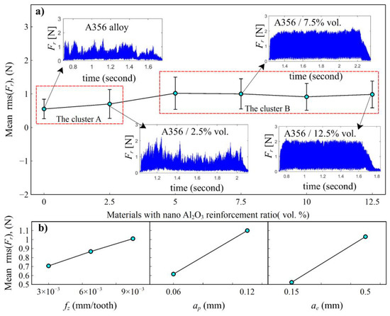
Figure 6.
Main effects plots of the average resultant cutting forces rms (Fr), (a) effect of the nano reinforcement ratio, (b) effects of the cutting parameters.
Table 2.
ANOVA table for the average resultant forces rms (Fr).
In order to provide deeper insight into the above-mentioned regularity of the cutting forces, a synthetic indicator is analyzed, consisting of the standard deviation of the average rms force values along the slot. If the rms keeps constant, the standard deviation is zero; otherwise, it increases. The signal in the central slot region is divided into five portions, and the standard deviation of the rms force value is extracted for each portion (Figure 7a). Entrance and exit regions were excluded since they involve the tool engagement and disengagement transients that kinematically affect force generation. According to the claims provided in the previous section, the quantitative analysis of the cutting forces’ regularity, shown in Figure 7a, reveals that the two clusters exist. Cluster A showed much more irregular micromilling forces compared to cluster B. These values represent the regularity or stability of cutting forces acquired during micromilling. The higher values mean the cutting forces are irregular for this test. The higher irregularity shown via cluster A is much higher, considering that lower magnitude average cutting forces occur in this cluster than in cluster B. The regularity of cutting forces is also affected by the process parameters. Each process parameter, feed/tooth, axial depth of cut, and radial depth of cut, affects the force regularity negatively. Lower parameter values result in more regular cutting forces (Figure 7b). ANOVA analysis indicates that factors, except for feed per tooth, are statistically meaningful for the regularity of cutting forces. When all factors are evaluated separately for each cluster, besides the great force regularity difference between the two clusters, the force regularity of cluster B was seen to be less affected by the reinforcement ratio and the process parameters with respect to cluster A (Figure 8a,b). On the other hand, the axial and radial depth of cut were statistically significant for cluster A and cluster B (Table 3).
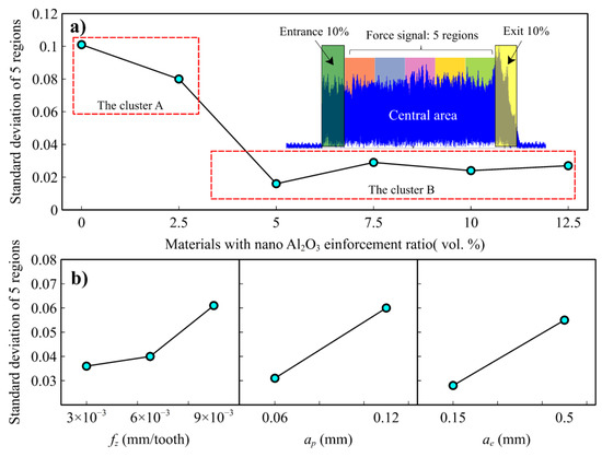
Figure 7.
Main effect plots of the regularity (standard deviation) of the resultant cutting force values, (a) effect of the nano reinforcement ratio, (b) effects of the cutting parameters.
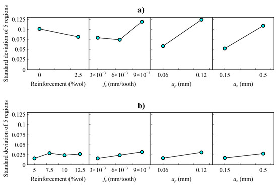
Figure 8.
Main effect plots of the regularity (standard deviation) of the resultant cutting force values. The analysis is split into (a) cluster A (A356 alloy and A356/2.5 vol.% Al2O3, (b) cluster B (A356/5–12.5 vol.% Al2O3).
Table 3.
ANOVA table for the regularity of the resultant cutting force.
This evidence regarding the regularity of the cutting forces can be given by systematic changes in the workpiece material homogeneity as well as a systematic change in the underlying cutting mechanisms. Since microstructural analysis confirms that there is no clear evidence of material inhomogeneity along the radial coordinate of the workpieces, as a function of increased nano reinforcement, the regularization of the cutting forces can be related to a systematic change in the cutting process itself.
3.3. Tool Wear Analysis
On one side, there are no doubts that the tools’ performance is directly influenced by the mechanical properties of the material and the volume fraction of nanoparticles, but on the other, the conducted micromachining tests revealed only a negligible impact on the tool wear. Given the limited cutting length carried out in the tests, a clear identification of the effect of the loading ratio on the tool wear was not possible. Figure 9 shows the SEM analysis of the tool wear after micromilling of the first (by tool-1) and second floors (by tool-2) of the workpieces. Although this kind of wear assessment could not quantify the rounding on the cutting-edge radius, the resulting images indicate that beyond the residual material sticking to the tool edge (see point A, Figure 9) and environmental debris (contamination, point C, Figure 9), negligible tool wear occurred during the conducted micromilling tests of MMCs.
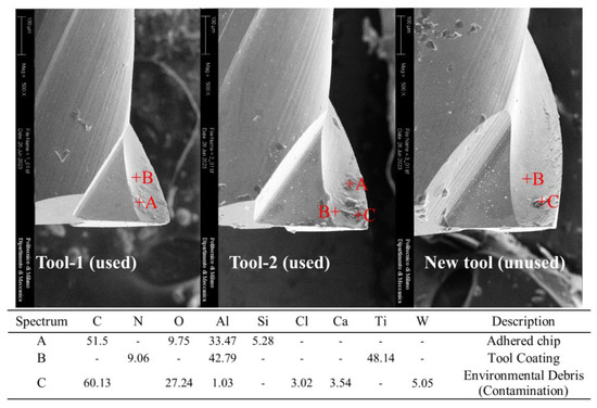
Figure 9.
Tool wear inspection (“Fresh tool” refers to a brand-new tool, and “Run” indicates the cumulated number of cutting passes carried by the tool).
3.4. Surface and Burr Formation Analysis
The generated surfaces and machining burrs are analyzed via microscope imaging (Figure 10). A considerable burr formation has occurred when micromilling cluster A (A356 and A356/2.5% vol. Al2O3), and the greatest burrs are noticed on A356 alloy (see Figure 10a). The burr formation was intensely observed in the entry wall of the tool cutting edge (left wall in the SEM images). A burr in the form of side bulging has occurred because of uncut chip accumulation on the tool entrance wall. Serrated burrs, rarely including shear bands, were formed on the tool exit edge. In materials with higher nano-reinforcement ratios, small, serrated burrs occurred in both walls with burr heights that decreased significantly with increasing reinforcement ratio. Since cluster A is composed of softer materials, increased burr, and surface worsening behaviors are linkable to a variation in the cutting tendency to develop plowing/rubbing mechanisms [14]. The nature of the micro deformation during plowing/rubbing is known to contribute significantly to increase cutting forces, burr formation, and worsening surface quality [35,36]. Harder materials tend to undergo lower plastic deformation and lower flow toward the feed direction. Despite an increased grain pull-off tendency with a consequent material pile up, an additional mechanism that can explain the burr results in the cluster A data, no available direct observations are collected to support this claim. Cluster B showed better slot quality characteristics with a much smaller burr formation (Figure 10c,d), and burrs get smaller for increased reinforcement ratios (the best results were observed on the A356/12.5% vol. Al2O3). It is also noticeable that the cutting parameters affect the burr formation but in a more limited way compared with the effects of nano reinforcement (Figure 10e). The lower feed rates, i.e., the lower the chip thicknesses, the lower the burrs, which is in agreement with the previous literature [37].
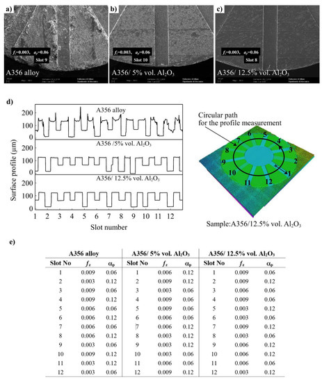
Figure 10.
Burr formation on the top surfaces of the workpieces, (a) SEM images of slot 9 on A356 alloy, (b) slot 10 on A356/5% vol. Al2O3, (c) slot 8 on A356/12.5% vol. Al2O3, (d) surface profiles of selected workpieces, (e) the cutting conditions of selected workpieces.
Figure 11 shows the mean effect plots of the Sa values concerning the reinforcement ratio and process parameters. Similar to the burr results, cluster A showed higher surface roughness than cluster B (Figure 11a). This quantitative evidence supports that nanoparticle reinforcement can alter the chip generation mechanisms, limiting the plowing/rubbing contributions and providing better surface qualities. While the surface roughness values were comparably high in A356 alloy, it was observed that the values decreased approximately three times with 5% vol. Al2O3 nano reinforcement. Figure 11b–d also supports the improvement of surface quality by indicating and comparing the 3D surface topographies of slot surfaces (A356 alloy, A356/5% vol., and A356/12.5% vol. Al2O3).
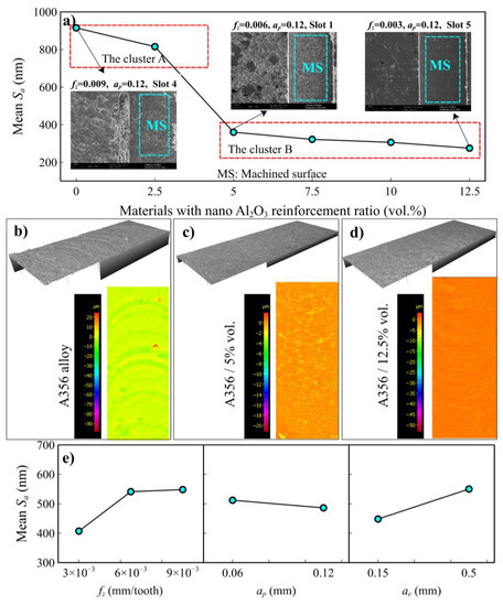
Figure 11.
(a) Mean effect plots of Sa (Average height of surface area) values versus reinforcement ratio, (b) 3D surface roughness images of slot 4 on A356 alloy, (c) slot 1 on A356/5% vol. Al2O3, (d) slot 5 on A356/12.5% vol. Al2O3, (e) main effect plots of Sa values versus process parameters.
As for the effects of machining parameters (Figure 11), the surface roughness increased with the increase in feed per tooth and decreased negligibly with the increase in the axial depth of the cut. ANOVA analysis given in Table 4 indicates that the depth of cut does not significantly affect surface quality. In addition, it was observed that the increase in the radial depth of the cut increased the surface roughness. The radial depth of the cut is also related to the contact time, and with that effect, there could have been a dynamic response of tool deflection. Different bending or deflection can produce different vibrations and different surface responses. But also, without bending, it would be some different chip evacuation/generation. When the clusters are focused individually (Figure 12), ANOVA analysis (Table 4) proves that reinforcement ratio does not have a statistical role on the surface roughness values. However, there are significant differences between the cluster, which is dominated by a change in the plowing/rubbing mechanism for all factors and levels. For cluster B, only feed per tooth is statistically significant on the surface roughness. The regularity of cutting forces and the surface quality results seem similar in trend (Figure 7 vs. Figure 11). This can be interpreted as the force regularity is highly related to surface quality. When these results are evaluated together, the nanocomposite material A356/10% vol. Al2O3 produces better surface quality and lower cutting forces. With that characteristic, this material served the optimum micromilling performance.
Table 4.
ANOVA table for the average surface roughness (Sa) values.
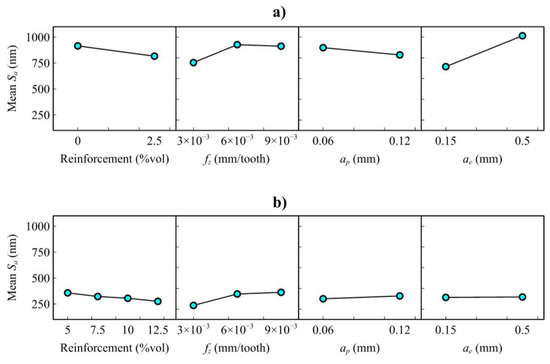
Figure 12.
Mean effect plots of Sa, (a) cluster A (A356 alloy and A356/2.5 vol.% Al2O3) and (b) cluster B (A356/5–12.5 vol.% Al2O3).
4. Conclusions
This study investigates the micromilling performance of a class of innovative A356/Al2O3 nanocomposite materials produced via the powder metallurgy route. By controlling the experiments throughout the entire process chain, from the production of the material to machining operations and post-processing measurements, this study allowed the generation of cross-processes knowledge that is required for developing real industrial applications with such pioneering materials. The carried multi-factorial experimental analysis included cutting forces and part quality indicators analysis and allowed us to quantify the effects of varying nano reinforcement loadings and cutting process parameters on the micro-cutting process.
The main finding of this work consists of the evidence that a threshold of the nano Al2O3 reinforcement content exists, namely the 5% vol. nano Al2O3, that allows a burr-free cutting process which is fundamental to enhancing the micromachinability of this ductile class of aluminum alloy materials. Passing this threshold with higher ceramic reinforcement ratios allows better surface quality with reduced burr and pile-up formations on the parts by regularizing cutting forces and cutting stability. The surface quality improved more than two times with the higher reinforcement ratios of ceramic reinforcement. Despite the higher volume fraction, which results in further internal porosity and slightly higher cutting forces, finer surface roughness was obtained via more regular cutting regimes. With the increase in the cutting force values, the regularity of cutting forces increased approximately fivefold. The absence or small contents of nanoparticle reinforcement can produce very dense but softer MMC parts that are easier to cut (lower cutting forces) but with a worse result in micromilling surface finishing and slot quality.
Incorporating nano reinforcement has proven to enhance cutting performance while promoting superior surface quality. The increased cutting forces present a higher effort required for the tool, but a heightened level of control over potential damage and breakage offsets this. No perceptible wear was observed in the cutting tool after 72 experiments in which tool wear was sequentially examined. The result is a cutting process that not only performs better but also results in a smoother and more refined surface finish due to the presence of nanoparticles. Further research could not only focus on the quantitative analysis of the effect of the tool’s wear mechanism but also encompass a comprehensive study of the same focus. In addition, future studies should be aimed at altering the sintering conditions and exploring the impact of various production parameters, such as sintering cycles and mechanical milling conditions, to gain a deeper understanding of the underlying mechanisms.
Author Contributions
Conceptualization, T.S., P.P., T.T., D.Ö. and M.A.; methodology, T.S., P.P., T.T., D.Ö. and M.A.; software, T.S. and P.P.; validation, T.S., P.P., T.T., D.Ö. and M.A.; formal analysis, T.S., P.P., T.T., D.Ö. and M.A.; investigation, T.S., P.P., T.T., D.Ö. and M.A.; resources, T.T., D.Ö. and M.A.; data curation, T.S., P.P., T.T., D.Ö. and M.A.; writing—original draft preparation, T.S. and P.P.; writing—review and editing, T.S., P.P., T.T., D.Ö. and M.A.; visualization, T.S. and P.P.; supervision, D.Ö. and M.A.; project administration, D.Ö. and M.A.; funding acquisition, T.S. and M.A.; All authors have read and agreed to the published version of the manuscript.
Funding
The authors express their gratitude to the Karabük University Research Fund for the financial support towards Project Number: FIR-2020-2314.
Data Availability Statement
The data presented in this study are available on request from the corresponding author.
Conflicts of Interest
The authors declare no conflict of interest.
References
- Raj, P.; Biju, P.L.; Deepanraj, B.; Menachery, N. A Systematic Review on Characterization of Hybrid Aluminium Nanocomposites. Mater. Today Proc. 2022, 72, 2139–2150. [Google Scholar] [CrossRef]
- Francois, C.; Poirier, J.P.; Trudel, Y. Enhancing Machinability of P/M Materials. J. Manuf. Mater. Process. 1994, 103, 193–199. [Google Scholar]
- Safari, J.; Akbari, G.H.; Delshad Chermahini, M. The Effect of Reinforcement Content and Milling Time on Microstructure and Mechanical Properties of Al-10Mg/XAl2O3 Nanocomposites. Mater. Sci. Eng. A 2013, 569, 86–91. [Google Scholar] [CrossRef]
- Gururaja, S.; Ramulu, M.; Pedersen, W. Machining of MMCs: A Review. Mach. Sci. Technol. 2013, 17, 41–73. [Google Scholar] [CrossRef]
- Na, H.B.; Xu, L.H.; Han, G.C.; Liu, S.K.; Lu, L.H. Machinability Research on the Micro-Milling for Graphene Nano-Flakes Reinforced Aluminum Alloy. Metals 2019, 9, 1102. [Google Scholar] [CrossRef]
- Ezatpour, H.R.; Torabi Parizi, M.; Sajjadi, S.A.; Ebrahimi, G.R.; Chaichi, A. Microstructure, Mechanical Analysis and Optimal Selection of 7075 Aluminum Alloy Based Composite Reinforced with Alumina Nanoparticles. Mater. Chem. Phys. 2016, 178, 119–127. [Google Scholar] [CrossRef]
- Rahimian, M.; Parvin, N.; Ehsani, N. Investigation of Particle Size and Amount of Alumina on Microstructure and Mechanical Properties of Al Matrix Composite Made by Powder Metallurgy. Mater. Sci. Eng. A 2010, 527, 1031–1038. [Google Scholar] [CrossRef]
- Chambers, A.R. The Machinability of Light Alloy MMCs. Compos. Part A Appl. Sci. Manuf. 1996, 27, 143–147. [Google Scholar] [CrossRef]
- Sankar, B.R.; Umamaheswarrao, P. Multi Objective Optimal Scheme for Machinability Aspects of Al6061-SiCp Metal Matrix Composite during End Milling—A Hybrid Approach. Mater. Today Proc. 2020, 21, 1260–1264. [Google Scholar] [CrossRef]
- Milan, M.T.; Bowen, P. Tensile and Fracture Toughness Properties of SiCp Reinforced Al Alloys: Effects of Particle Size, Particle Volume Fraction, and Matrix Strength. J. Mater. Eng. Perform. 2004, 13, 775–783. [Google Scholar] [CrossRef]
- Mazahery, A.; Abdizadeh, H.; Baharvandi, H.R. Development of High-Performance A356/Nano-Al2O3 Composites. Mater. Sci. Eng. A 2009, 518, 61–64. [Google Scholar] [CrossRef]
- Sunar, T.; Özyürek, D. Effect of Al2O3 nanoparticles as reinforcement on the wear properties of A356/Al2O3 nanocomposites produced by powder metallurgy. J. Tribol. 2022, 144, 081701. [Google Scholar] [CrossRef]
- Asm, I. Machining of Aluminum Alloys. In ASM Handbook; ASM International: Almelle, The Netherlands, 1989; Volume 16, pp. 761–804. [Google Scholar]
- Rodrigues, A.R.; Jasinevicius, R.G. Machining Scale: Workpiece Grain Size and Surface Integrity in Micro End Milling. In Microfabrication and Precision Engineering, 2nd ed.; Davim, J.P., Ed.; Woodhead Publishing: Sawston, UK, 2017; pp. 27–68. [Google Scholar]
- Popov, K.; Dimov, S.; Pham, D.T.; Minev, R.; Rosochowski, A.; Olejnik, L.; Richert, M. The Effects of Material Microstructure in Micro-Milling. In 4M 2006—Second International Conference on Multi-Material Micro Manufacture, 2nd ed.; Menz, M., Dimov, S., Fillon, B., Eds.; Elsevier Ltd.: Amsterdam, The Netherlands, 2006; pp. 127–196. [Google Scholar]
- Joel, J.; Anthony Xavior, M. Optimization on Machining Parameters of Aluminium Alloy Hybrid Composite Using Carbide Insert. Mater. Res. Express 2019, 6, 116532. [Google Scholar]
- Liu, J.; Li, J.; Xu, C. Cutting Force Prediction on Micromilling Magnesium Metal Matrix Composites with Nanoreinforcements. J Micro Nanomanuf. 2013, 1, 011010. [Google Scholar] [CrossRef]
- Li, J.; Liu, J.; Xu, C. Machinability Study of Sic Nano-Particles Reinforced Magnesium Nanocomposites During Micro-Milling Processes. In Proceedings of the International Manufacturing Science and Engineering Conference, Erie, PA, USA, 2–3 July 2010; pp. 391–398. [Google Scholar]
- Premnath, A.A.; Alwarsamy, T.; Rajmohan, T. Experimental Investigation and Optimization of Process Parameters in Milling of Hybrid Metal Matrix Composites. Mater. Manuf. Process. 2012, 27, 1035–1044. [Google Scholar] [CrossRef]
- Parenti, P.; Cazzani, A.; Annoni, M. Cutting force modelling in green machining of polymer-based metallic feedstock. J. Mater. Process. Technol. 2023, 312, 117825. [Google Scholar] [CrossRef]
- Campos, F.d.O.; Mougo, A.L.; Araujo, A.C. Study of the Cutting Forces on Micromilling of an Aluminum Alloy. J. Brazilian Soc. Mech. Sci. Eng. 2017, 39, 1289–1296. [Google Scholar] [CrossRef]
- Liu, J.; Cheng, K.; Ding, H.; Chen, S. Realization of Ductile Regime Machining in Micro-Milling SiCp/Al Composites and Selection of Cutting Parameters. Proc. Inst. Mech. Eng. Part C 2019, 233, 4336–4347. [Google Scholar] [CrossRef]
- Liu, J.; Cheng, K.; Ding, H.; Chen, S.; Zhao, L. An Investigation of the Influence of Phases’ Removal Ways on Surface Quality in Micro Milling SiCp/Al Composites. Procedia CIRP 2018, 71, 59–64. [Google Scholar] [CrossRef]
- Jeyakumar, S.; Marimuthu, K.; Ramachandran, T. Prediction of Cutting Force, Tool Wear and Surface Roughness of Al6061/SiC Composite for End Milling Operations Using RSM. J. Mech. Sci. Technol. 2013, 27, 2813–2822. [Google Scholar] [CrossRef]
- Teng, X.; Huo, D.; Wong, W.L.E.; Sankaranarayanan, S.; Gupta, M. Machinability investigation in micro-milling of Mg based MMCs with nano-sized particles. In Magnesium Technology; Springer International Publishing: Cham, Switzerland, 2017; pp. 61–69. [Google Scholar]
- Pramanik, A.; Zhang, L.C.; Arsecularatne, J.A. Prediction of Cutting Forces in Machining of Metal Matrix Composites. Int. J. Mach. Tools Manuf. 2006, 46, 1795–1803. [Google Scholar] [CrossRef]
- Pramanik, A.; Zhang, L.C.; Arsecularatne, J.A. Machining of Metal Matrix Composites: Effect of Ceramic Particles on Residual Stress, Surface Roughness and Chip Formation. Int. J. Mach. Tools Manuf. 2008, 48, 1613–1625. [Google Scholar] [CrossRef]
- Teng, X.; Huo, D.; Chen, W.; Wong, E.; Zheng, L.; Shyha, I. Finite Element Modelling on Cutting Mechanism of Nano Mg/SiC Metal Matrix Composites Considering Cutting Edge Radius. J. Manuf. Process. 2018, 32, 116–126. [Google Scholar] [CrossRef]
- Manna, A.; Bhattacharayya, B. A Study on Machinability of Al/SiC-MMC. J. Mater. Process. Technol. 2003, 140, 711–716. [Google Scholar] [CrossRef]
- Manna, A.; Bhattacharayya, B. Influence of Machining Parameters on the Machinability of Particulate Reinforced Al/SiC-MMC. Int. J. Adv. Manuf. Technol. 2005, 25, 850–856. [Google Scholar] [CrossRef]
- Afsharhanaei, A.; Rebaioli, L.; Parenti, P.; Annoni, M. Finite element modeling of micro-orthogonal cutting process with dead metal cap. Proc. Inst. Mech. Eng. Part B 2018, 232, 1351–1361. [Google Scholar] [CrossRef]
- Yousefi, R.; Kouchakzadeh, M.A.; Rahiminasab, J.; Kadivar, M.A. The Influence of SiC Particles on Tool Wear in Machining of Al/SiC Metal Matrix Composites Produced by Powder Extrusion. Adv. Mater. Res. 2011, 325, 393–399. [Google Scholar] [CrossRef]
- Baruffi, F.; Parenti, P.; Cacciatore, F.; Annoni, M.; Tosello, G. On the application of replica molding technology for the indirect measurement of surface and geometry of micromilled components. Micromachines 2017, 8, 195. [Google Scholar] [CrossRef]
- Suryanarayana, C. Mechanical Alloying and Milling. Prog. Mater. Sci. 2001, 46, 1–184. [Google Scholar] [CrossRef]
- Sun, X.; Cheng, K. Chapter 2—Micro-/Nano-Machining through Mechanical Cutting. In Micromanufacturing Engineering and Technology, 2nd ed.; Qin, Y., Ed.; William Andrew: Norwich, NY, USA, 2015; pp. 35–58. [Google Scholar]
- Thakre, A.A.; Soni, S. Modeling of Burr Size in Drilling of Aluminum Silicon Carbide Composites Using Response Surface Methodology. Eng. Sci. Technol. Int. J. 2016, 19, 1199–1205. [Google Scholar] [CrossRef]
- Chen, J.P.; Gu, L.; He, G.J. A Review on Conventional and Nonconventional Machining of SiC Particle-Reinforced Aluminium Matrix Composites. Adv. Manuf. 2020, 8, 279–315. [Google Scholar] [CrossRef]


Disclaimer/Publisher’s Note: The statements, opinions and data contained in all publications are solely those of the individual author(s) and contributor(s) and not of MDPI and/or the editor(s). MDPI and/or the editor(s) disclaim responsibility for any injury to people or property resulting from any ideas, methods, instructions or products referred to in the content. |
© 2023 by the authors. Licensee MDPI, Basel, Switzerland. This article is an open access article distributed under the terms and conditions of the Creative Commons Attribution (CC BY) license (https://creativecommons.org/licenses/by/4.0/).