Article

Influence of Sheet Covers on Filling Behavior in Electrochemical Joining of Additively Manufactured Components

Institute for Product Development and Machine Elements, Technical University of Darmstadt, Otto-Berndt-Straße 2, 64287 Darmstadt, Germany
*
Author to whom correspondence should be addressed.
J. Manuf. Mater. Process. 2023, 7(5), 157; https://doi.org/10.3390/jmmp7050157
Submission received: 31 July 2023 / Revised: 18 August 2023 / Accepted: 23 August 2023 / Published: 25 August 2023

Abstract

:
This paper focuses on the electrochemical joining of additively manufactured components using simulation-based and experimental methods. The study investigates the influence of cover screens on the filling behavior of the joining zone. Experimental methods involving additive manufacturing and electroplating are combined with simulation models to provide a realistic representation of the joining process. The results show a good agreement between the simulated and experimental findings, indicating the applicability of the simulation model. The parameter study reveals that higher cover factors result in a decrease in the excess material ratio, indicating reduced material deposition outside the joining zone. The filling time required to completely fill the joining zone is influenced by both the cover size and the opening angle of the joining zone. The optimal parameter combinations depend on whether the filling time or the excess material volume is to be minimized. Cavity formation within the joining zone was identified as a critical factor affecting the completeness of the filling. The study provides insights into the influence of cover screens on the electrochemical joining process and offers guidance for optimizing the design of the joining zone.

1. Introduction

Additive manufacturing (AM) has gained significant attention in recent years due to its potential for creating complex geometries, reducing material waste, and shortening production times [1]. In order to fully exploit this potential, rules and methods are currently being developed that are referred to as the design for additive manufacturing. These include, for example, the systematic linking of knowledge about additive manufacturing with the development process using the design pattern matrix [2] or the methods developed in recent years for differentiated design in additive manufacturing. Differential design describes the design principle of breaking down components into individual parts [3]. These methods can be divided into manual [4], interactive [5,6], and automatic [7] methods according to the degree of human influence on component separation. Reasons for using a differential design are, for example, the reduction in manufacturing costs [6], modularization of the product [8], or simply that the component dimensions exceed the build space dimensions of the manufacturing machine [8,9]. However, the joining of the separated components required after fabrication is not considered sufficiently or at all in these methods. The challenge is to effectively join these additively manufactured components, ensure their structural integrity, and maintain the desired mechanical properties. Particularly challenging is the joining of additively manufactured metal components, which can be produced by the laser-based powder bed fusion (L-PBF) process, for example. Many joining techniques investigated in the literature are limited to simple joining geometries, which are easily accessible. However, complicated and inaccessible joining zone geometries occur, for example, in components separated by differential design methods [6].
Several research papers have explored joining techniques for additively manufactured metal components. Gill et al. conducted a study focusing on the rework and repair of metal parts produced through L-PBF and electron beam powder bed fusion (EB-PBF). They found that gas tungsten arc welding (GTAW) and friction stir welding (FSW) are feasible joining techniques for these additively manufactured components. These methods have shown potential in providing reliable joining capabilities and preserving the integrity of the metal parts [10]. Hassanin et al. investigated the joining process of additively manufactured parts made of Ti6Al4V and AlSi10Mg. The study identified linear friction welding and friction stir welding as suitable techniques for joining these specific materials. These processes exhibited the potential to create strong bonds between dissimilar metals, ensuring the structural integrity of the joined components [11]. Yuce et al. conducted a comprehensive review of the scientific research concerning the joining techniques of dissimilar materials, including mechanical joining, clinching, self-pierce riveting, friction welding, and laser welding [12]. Furthermore, Hinojos et al. explored the feasibility of joining Inconel 718 with 316L Stainless Steel using electron beam melting (EBM). The study demonstrated that the EBM process can achieve high-quality metallurgical joints while minimizing thermal damage to the surrounding material [13].
All the joining processes described above have in common that the joining zone between the components to be joined must be simple and easily accessible for auxiliary tools. Electrochemical joining is proving to be a promising approach, especially for components with complex geometries. In this joining process, also known as galvanic joining, metal ions are deposited on the surface of the joining zone of the metal components to be joined in order to produce a material bond. Due to the nature of the process, the joining process can, thus, take place at several points at the same time, which enables complicated joining, such as the joining of additively manufactured metal lattice structures. In addition, the joining process is, to some extent, independent of the geometry of the joining zone, since the material is deposited on all non-insulated areas exposed to the electrolyte and no further auxiliary tools are required. However, the edges of the joining zone are exposed to a higher current intensity than in the center of the joining zone, resulting in higher material deposition at the edge [14,15,16]. Rudolph et al. investigated the influence of V-shaped joining zone geometry on layer formation during the electrochemical joining of additively manufactured specimens made of AlSi10Mg by the L-PBF process. Key findings include the description of the impact of the opening angle on layer uniformity through the introduction of a ratio of layer thickness in the middle and the edges of the joining zone, as well as the importance of shaping geometry for achieving desired contours. In order to reduce excessive material accumulation at the edges of the joining zone, the use of cover screens is proposed and experimentally investigated. It was shown that the electrochemical joining process can be positively influenced by the use of cover screens, leading to significantly reduced material deposition beyond the edge of the joining zone and a relocation of the material agglomeration from the edges towards the direction to the center of the joining zone, as is shown in Figure 1. Thus, the uniformity of the layer thickness distribution is improved compared to the specimen without a cover [17]. Rudolph et al. also investigated the tensile strength and causes of failure for specimens fabricated by the L-PBF process from AlSi10Mg and electrochemically joined with nickel and with copper, respectively. The tensile strength for specimens joined with nickel is 127.4 MPa and for specimens joined with copper is 83.2 MPa. The causes of failure include delamination in the zinc layer, which is necessary as an intermediate layer for the electroplating of aluminum base materials [14].
Simulation-based methods have proven useful in predicting and optimizing manufacturing processes, including additive manufacturing [18] and electrodeposition processes [19,20,21]. In this study, we aim to investigate the influence of cover screens on the filling behavior of the joining zone during the electrochemical joining of additively manufactured components using simulation-based techniques. For the experimental studies, polymer components electroplated with copper are used instead of L-BPF fabricated metal components. These are significantly less complicated and less expensive to manufacture and fulfill the same purpose, since only geometric influences on the filling behavior are to be investigated. The purpose of this research is twofold: (1) to expand our understanding of the impact of cover screen parameters on filling behavior and (2) to provide recommendations for optimizing the design of the joining zone, ultimately leading to improved quality and performance of the joined components.

2. Materials and Methods

The following section describes the governing equations and the simulative and experimental methods used.

2.1. Governing Equations

The governing equations are described in detail in the literature [21]. In the following, only the equations required for the model are presented. The electrochemical systems consist of electrically conductive media, which can be classified into electrodes and the electrolyte. Electrodes transmit current via electrons and are mostly made of metal. The electrolyte transfers current by transporting charged ions and, in many cases, consists of a salt solution in water. In the electrolyte, the net current density is described as the sum of the currents of all ions [22]:
i l = F i z i N i .
Here, i l is the vector of current density (A/m 2 ) in the electrolyte, F is for Faraday’s constant (C/mol), and N i for the flux of the species (mol/(m 2 s)) with a charge number z i . The Nernst–Planck equation governs the ion flux in an ideal electrolyte solution, incorporating diffusion, migration, and convection as the first, second, and third terms, respectively, to account for the flux of the solute species [22]:
N i = D i c i z i u i F c i Φ l + c i u ,
where c i is the concentration of ion i (mol/m 3 ), D i is its diffusion coefficient (m 2 /s), u i is its mobility (s·mol/kg), Φ l is the electrolyte potential, and u is the velocity vector (m/s). In addition, the current conservation is valid considering a general electrolyte current source term:
· i l = Q l .
The general treatment of electrochemical theory is usually too complex to be practical. If it is assumed that one or more of the terms in Equation (2) are negligible, the equations can be simplified and linearized. Assuming good electrolyte mixing and high electrolyte concentration, two assumptions are made: First, the electrolyte is assumed to be electroneutral, thereby eliminating the convective contribution to the current density in Equation (2). Second, the variations in the electrolyte composition are assumed to be negligible, thereby eliminating the diffusive contribution to the current density in Equation (2) and allowing the treatment of ionic strength as constant. Substituting Equation (2) into Equation (1) and neglecting the diffusive and convective terms yields Ohm’s law for the current density in the electrolyte:
i l = σ l Φ l .
Here, σ l denotes the conductivity of the electrolyte, which is constant within the electrolyte under the above assumptions. The anode and cathode are made of copper, as it is comparatively easy to deposit from aqueous electrolytes. Their current–voltage relationship also follows Ohm’s law:
i s = σ s Φ s
with current conservation
· i s = Q s ,
which acts as a boundary condition for the simulation. Copper is dissolved at the dissolution electrode (anode):
C u ( s ) C u 2 + + 2 e
while on the deposition electrode, (cathode) copper is deposited:
C u 2 + + 2 e C u ( s )
In addition to maintaining the current in the electrodes and electrolyte, the interface between the electrode and electrolyte must also be considered. Here, too, the current must be maintained. The current transfer between the electrode and electrolyte takes place via an electrochemical reaction, where the reaction rate depends, among other things, on the activation overpotential that occurs at the interface. The activation overpotential η corresponds to the difference between the actual potential difference and the equilibrium potential E e q :
η = Φ s Φ l E e q .
A simplified electrode kinetic model is assumed for both electrodes. The linearized Butler–Volmer model establishes a linear relationship between the overpotential and the reaction current density of the electrode [22]:
i l o c = i 0 ( α a + α c ) F R T η .
In the linear Butler–Volmer equation for the reaction above, i l o c stands for the local charge transfer current density, i 0 for the exchange current density, and α a for the anodic and α c for the cathodic charge transfer coefficient. R is the universal gas constant and T the temperature. This equation describes the case where the charge transfer of an electron is the rate-determining step in the net charge transfer reaction. The deposition electrode is grounded and an electric potential of 0.5 V is applied to the dissolution electrode. All other boundaries are insulating:
n · i l = 0
n · i s = 0
where n denotes the normal vector to the boundary. Due to the copper deposition at the cathode, the electrode boundary moves during the time-dependent simulation. The molar flux of copper N C u (mol/(m 2 · s)) across the electrodes is described by Faraday’s law [22]:
N C u = ν C u i l o c n F .
The stoichiometric coefficients for copper ν C u are one for both electrode reactions, and the number of electrons n is two. The deposition velocity v d e p , which is directed in the normal direction of the electrode in the electrolyte domain, can be calculated from the molar flux, density, and molar mass of copper:
v d e p = M C u N C u ρ C u .

2.2. Simulation Model

The FE software Comsol Multiphysics and its Electrodeposition Module are used to simulate the process, see Table 1 for the simulation parameter used. Based on the assumptions made, a secondary current distribution with deformed geometry is modeled. A 0.8 mol/L CuSO 4 and 0.8 mol/L H 2 SO 4 solution with a conductivity σ l of 0.115 Ω 1 cm 1 is chosen as the electrolyte, with H 2 SO 4 acting as the supporting electrolyte due to its high proton conductivity. The model is based on the work of Deconinck [23].
The geometry of the electrolyte domain is modeled parametrically to allow automated parametric studies. The model is two-dimensional and consists of a dissolving and a depositing electrode. Only the electrolyte region (light gray) is modeled in geometry; see Figure 2. In the previous work, the joining zone between the two components was designed in the shape of a wedge with an opening angle of α in order to allow the joining zone to be filled and, thus, create a material bond [17].
The anode has a width of 40 mm, and the distance between the surface of the specimens and the anode is 20 mm. The joining zone has a depth of 3 mm; the joining zone width is geometrically determined by the opening angle α . To study the influence of the sheet cover, its shape is geometrically subtracted from the electrolyte domain. The cover has a thickness of 2 mm, and the edges of the cover are insulated. The cover factor X describes how far the cover protrudes into the joining zone. With a cover factor of one, the joining zone is completely covered, while with a cover factor of zero, the cover ends exactly at the edge of the joining zone.
For mesh generation, the predefined setting “finer” was used, which is associated with a maximum element size of 1.48 mm. The results show that only the local resolution of the mesh at the surface of the joining zone has a relevant influence on the calculation. For the surface of the joining zone and for the edges of the cover adjacent to the joining zone, the maximum element size of the mesh was reduced to 0.05 mm to allow sufficient resolution of the relevant area.
Material deposition within the joining zone leads to the need for deformation of the mesh over time. For this purpose, the deformed electrode function integrated in Comsol Multiphysics is used. Through this function, the mesh is deformed and smoothed according to the electrolytic deposition. For large deformations, this can lead to errors in the mesh and singularities in the calculation. For this reason, the function for automatic remeshing is activated as soon as the mesh quality falls below a defined value. The mesh quality is expressed by the ratio of length to width of the elements. For a regular mesh, this value is approximately one; see Figure 3. Due to the deformation of the mesh as a result of electrochemical material deposition, the ratio can assume significantly smaller values. The limit value of the ratio for remeshing is chosen to be 0.1, which is a typical limit value.

2.3. Experimental Methods
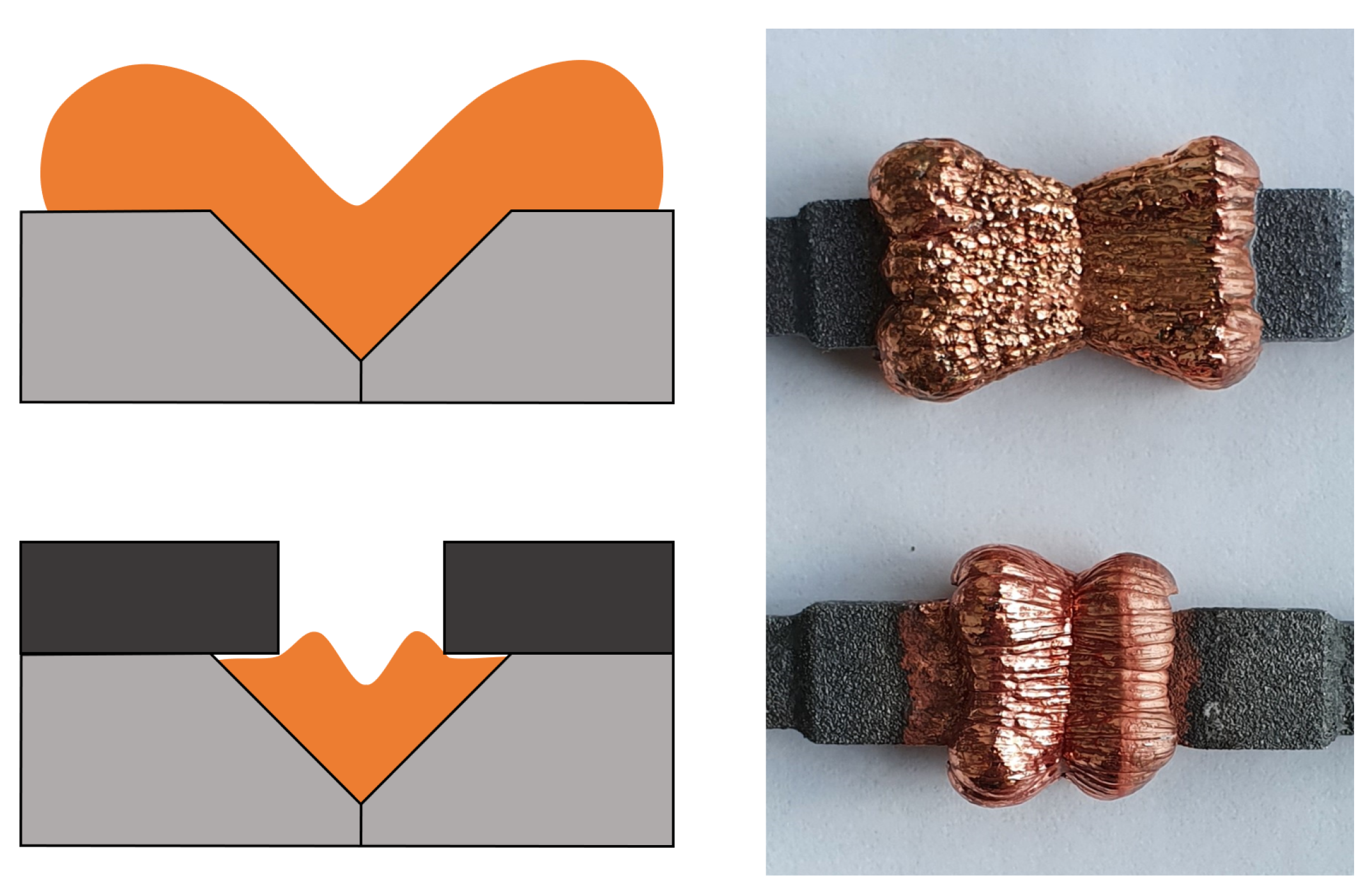
Electrochemical joining is a process for joining additively manufactured metal components. However, the production of metal components is significantly more complex and expensive than the production of polymer components by additive processes. Based on Schork’s approach [24], the requirements for the prototype to be tested were, therefore, determined. The objective of the investigation carried out here is limited to the influence of the geometry of the cover and the joining zone on the filling behavior. In addition, the complexity of the specimens was further reduced by not splitting them into two components to be joined. The type of initial contact of the components to be joined (point contact, line contact, or surface contact) will be investigated in the future work and should be excluded from consideration here. It is to be expected that the type of contact also has an influence on the distribution of the current density and, thus, on the joint. Since the mechanical properties of the joint are not of interest at this stage, the specimens for the experimental investigations are produced by a combination of the additive stereolithography process (SLA/MSLA) and an electroplating pre-coating with copper. This allows the geometry of the joining zone to be reproduced and, at the same time, provides the metallic surface of the cathode necessary for electrodeposition. Figure 4 shows an example of one of the specimens, each of which consists of the base body and the cover. The base body is shown on the left, and the base body including the cover is on the right. The specimens are designed parametrically and are determined by the opening angle α and the cover factor X. The parameter values are geometrically engraved for clear differentiation of the specimens.
The specimens and cover plates are fabricated on an Anycubic Photon Mono X MSLA printer (Shenzhen Anycubic Technology Co., Ltd., Shenzhen, China). The XY resolution is 50 µm and the selected layer height is also 50 µm. The cover plates must be made of an electrically insulating material, so plastic is ideal for this. The material used is Siraya Tech Fast Resin (Siraya Tech, San Gabriel, CA, USA) for both, which enables comparatively simple fabrication with high precision and low shrinkage. After the completion of the printing process, the specimens are separated from the build platform and cleaned in isopropanol. After drying, they are cured for six minutes in a UV curing chamber at room temperature. Figure 5 shows the preparation process of the specimens. To make the specimens electrically conductive, they are coated with a copper conductive paint and then dried for 24 h at room temperature (a). They are then electroplated with copper for 15 min at a current density of 200 A/m 2 and rinsed in deionized water (b). The corresponding cover plate is placed on the prepared specimen (c) and fixed with insulating tape (d).
The specimens are then electroplated with copper for 48 h at a current density of 200 A/m 2 . The Tifoo brand bright copper electrolyte is used as the electrolyte. The distance between the specimens surface and the copper anode is 20 mm. To ensure good mixing of the electrolyte, the stirring function of the electroplating equipment remains switched on for the full duration. The plating process takes place at room temperature, which was 25 °C at the time of the experiments. As soon as the coating process is completed, the specimens are rinsed with deionized water and dried. The time at which the joining zone is completely filled can only be estimated for the experimental investigations. For this reason, predicting the required filling time by simulating the process is another objective of the investigation. Subsequently, the relevant joining zone area is separated from the overall specimen by means of a wet cutting grinder and embedded in epoxy resin. After the resin has cured, the specimens are ground down to half of the joining zone. Sandpaper with increasingly finer grit is used for this purpose, with the finest sandpaper having a grit of 2400. The prepared specimens are then examined under the Axioplan light microscope from Zeiss with an integrated Axiocam 105 color camera, and micrographs are taken. Fusion 360 CAD-Software is used to evaluate the micrographs and determine the profile line. The images are loaded, calibrated, and oriented to the CAD-Geometry of the specimens. The profile line is traced and interpolated using the Sketch function. The determined profile is exported and can be imported and evaluated in MATLAB.
One of the objectives of the investigations is to determine which combination of the parameters cover factor and opening angle leads to the most uniform deposition and low material excess. To evaluate this, the excess ratio Φ E is introduced. This relates the cross-sectional area of the excess material A e and that of the joining zone material A j (see Figure 6) and is formed as follows:
Φ E = A e + A j A j
Thus, it represents the ratio of the total deposited cross-sectional area and the cross-sectional area of the joining zone. If Φ E is equal to one, the whole material is deposited only in the joining zone. The excess ratio is only calculated when the joining zone is completely filled without cavities.

3. Results

Figure 7 shows an example comparison of the experimental and simulated results based on the specimens with an cover factor of 0 (left) and 0.25 (right) for an opening angle of 110° after a joining time of 48 h. The measured profile line is shown in black and the simulation result in blue. The initial geometry of the joining zone is shown in orange. The results of the simulation show a great agreement with the experimentally determined profiles.
The deviation in the measured and simulated curve at the edges of the cover is probably due to the secondary current distribution used in the simulation. Compared to the models that do not neglect convection and diffusion within the electrolyte, this leads to a more uniform material deposition. In addition, a slight asymmetry can be seen, which is probably due to a slight skewing of the specimens within the electrolyte bath. The most important factor for calculating the total time required to completely fill the joining zone is the deposition height at the bottom of the joining zone. Here, all simulations show good agreement with the measured values. With some combinations of the parameters cover factor and opening angle, cavities are formed within the joining zone, which prevent complete filling (see Figure 8). In the simulation, this behavior is manifested by a termination of the calculation at the time of cavity formation. The coalescence of the deposited material results in a separation of the electrolyte domain into two regions. However, no boundary conditions can be assigned to the newly formed region within the calculation process, which is why the calculation is aborted and an error message is output. The calculated data are also stored for this case, which allows us to determine the time at which the cavity formation starts. However, solutions containing a cavity are excluded for further consideration and no excess ratio is determined. For use as a joining process, it must be possible to fill the joining zone completely.
Figure 9 gives an overview of the parameter combinations investigated by the simulation. The red dots represent the combinations where cavities were formed, and the green dots represent the combinations where the joining zone could be completely filled. Regardless of the cover factor, cavity formation always occurred for an opening angle of 70°. Interestingly, high cover factors ( X 0.6 ) ensure that cavities are avoided for an opening angle of 80°. From an opening angle of 90°, cavities no longer occur regardless of the cover factor.
In Figure 10, the convergence behavior of the time-dependent solver is depicted. The underlying data are output by default by Comsol Multiphysics for each simulation. The graph illustrates the reciprocal of the step size as a function of time steps during the simulation of the filling behavior. This simulation was performed with a cover factor of 0.2 and an opening angle of 90°. In the transient simulation, a discrete solution representing the time behavior of the electrochemical processes is calculated. This solution is deemed valid once it meets the predefined error limits. The graph reveals that the reciprocal of the step size begins at an elevated value, indicating a smaller initial time step. As the simulation advances, the time step size progressively increases. Notably, there are instances where the value surges, followed by a sharp decline. Such occurrences mark the points where remeshing is necessitated due to the degradation in mesh quality from significant mesh deformations.
Figure 11 shows the results of the parameter study, excluding the combinations in which cavities are formed. The left graph shows the described excess ratio ϕ E as a function of the cover factor X and the opening angle α . It can be clearly seen that the excess ratio decreases with larger values for the cover factor and converges towards one. The maximum value for the excess ratio occurs with a cover factor of zero and an opening angle of 90°. For this combination, the excess ratio has a value of 4.33, which means that more than four times the amount of material must be deposited than would be necessary to completely fill the joining zone. The lowest value of ϕ E can be found for X = 0.7 and α = 110 , where it is 1.1. For this combination, only 10% more material than necessary must be deposited. It should be noted that there is no significant relationship between ϕ E and α . In contrast to the cover factor, the opening angle, therefore, has no significant influence on the excess ratio.
The right graph shows the filling time t F , which is required to completely fill the joining zone, as a function of the cover factor and the opening angle. For use as a joining process, the aim is to achieve a minimum filling time without the formation of cavities. It was shown that the filling time required decreases in principle with higher cover factors. However, the filling time required increases slightly again for high cover factors, so that a local minimum can be identified for each opening angle. In contrast to the excess ratio, the filling time shows a clear dependence on the opening angle. The smaller the opening angle, the shorter the time required to fill the joining zone. This can be explained by the higher material volume required for larger opening angles at constant joining zone depth.
Table 2 shows the minimum values of the excess factor ϕ E and the filling time t F for the respective opening angles α . While the excess ratio is almost constant at its minimum value of ϕ E = 1.1 with a cover factor of X = 0.7 , the global minimum of the filling time is found at an opening angle of α = 80 and a cover factor of X = 0.6 . For this parameter combination, the excess ratio is 1.21.

4. Discussion

By analyzing the parameter combinations of cover factor X and opening angle α , important insights into the filling behavior of the joining zone were obtained. The excess material ratio ϕ E , which represents the ratio of the total deposited cross-sectional area to the cross-sectional area of the joining zone, was used as a measure of the relative excess material deposition. It was found that higher cover factors resulted in a decrease in the excess ratio, indicating that less material is deposited outside the joining zone. This reduces the amount of post-processing required for the joining process and increases resource efficiency. Furthermore, the coverage factor and opening angle influence the time t F required to completely fill the joining zone. The optimum values for opening angle and cover factor depend on whether the filling time or the excess material volume is to be minimized. This conflict of objectives must be considered and resolved on an application-specific basis.
The combination of experimental investigations and simulation-based techniques proved to be effective for studying the electrochemical joining process. The experimental fabrication of specimens using additive manufacturing and electroplating allowed a realistic representation of the geometry of the joining zone. The simulation model, which considered factors such as current density, electrode kinetics, and current transfer at the electrode–electrolyte interface accurately predicted the filling behavior and supported the interpretation of the experimental results. Nevertheless, discrepancies between the simulated and experimentally determined profiles occurred at the edges of the joining zone. This is probably due to the underlying secondary current distribution of the simulation, which neglects the diffusion and convection processes within the electrolyte. It is possible that the covers prevent sufficient mixing of the electrolyte within the joining zone region, making diffusion processes relevant. In addition, a simplified linearized relationship between the overpotential and the electrode reaction current density was assumed in the model. The nonlinear Butler–Volmer relationship could further improve the prediction of the behavior in the edge regions. To investigate this, an extended simulation model is currently being worked on that will be able to further improve the prediction performance of the model.
Cavity formation within the joining zone was identified as a critical factor influencing the completeness of the filling. Both the experimental investigations and the simulations showed that cavity formation occurs for certain parameter combinations, leading to incomplete filling. In the simulations, cavity formation leads to termination of the computational process. The goal of the further research is to represent the cavity formation in the simulation. For practical application as a joining process, it is crucial that the joining zone can be completely filled without cavities forming. Those parameter combinations where cavity formation occurred were identified and serve as a guideline for future users.
As the joining zone complexity increases, so does the complexity of the cover geometry. Further studies are needed to investigate how these complex geometries can be manufactured and assembled. Integration of the cover into the geometry of the joining zone is also conceivable if it is appropriately isolated. For the sake of simplicity and comparability, the wedge-shaped geometry of the joining zone was used here. The adaptation of the wedge shape to, for example, a parabolic or semicircular shape is possible. The filling behavior should also be simulatively investigable with the presented model.
It is worth noting that this study focused primarily on the filling behavior of the joining zone and did not investigate the mechanical properties of the joints. The further research could explore the mechanical characterization of the electrochemically joined components to assess the strength, durability, and reliability of the joints. In addition, the long-term performance and stability of the connected components under various operating conditions must be studied for practical applications.

Author Contributions

Conceptualization, M.N.; methodology, M.N. and K.R.; validation, M.N., K.R., and R.B.; investigation, M.N. and R.B.; resources, M.N.; data curation, M.N.; writing—original draft preparation, M.N.; writing—review and editing, R.B.; visualization, M.N.; supervision, E.K.; project administration, E.K. All authors have read and agreed to the published version of the manuscript.

Funding

We acknowledge support by the Deutsche Forschungsgemeinschaft (DFG—German Research Foundation) and the Open Access Publishing Fund of Technical University of Darmstadt.

Data Availability Statement

The data presented in this study are available on request from the corresponding author.

Conflicts of Interest

The authors declare no conflict of interest.

References

  1. Gibson, I.; Rosen, D.W.; Stucker, B. Additive Manufacturing Technologies: 3D Printing, Rapid Prototyping and Direct Digital Manufacturing, 2nd ed.; Springer: New York, NY, USA, 2015. [Google Scholar]
  2. Würtenberger, J.; Reichwein, J.; Kirchner, E. Using the potentials of additive manufacturing by a systematic linkage of the manufacturing process to product design. In DS 92: Proceedings of the DESIGN 2018 15th International Design Conference, Dubrovnik, Croatia, 21–24 May 2018; pp. 1465–1476. Available online: https://www.designsociety.org/publication/40551/USING+THE+POTENTIALS+OF+ADDITIVE+MANUFACTURING+BY+A+SYSTEMATIC+LINKAGE+OF+THE+MANUFACTURING+PROCESS+TO+PRODUCT+DESIGN (accessed on 30 July 2023).
  3. Krause, D.; Gebhardt, N. Methodische Entwicklung Modularer Produktfamilien; Springer: Berlin/Heidelberg, Germany, 2018. [Google Scholar] [CrossRef]
  4. Urbanic, R.J.; Hedrick, R. Fused Deposition Modeling Design Rules for Building Large, Complex Components. Comput.-Aided Des. Appl. 2016, 13, 348–368. [Google Scholar] [CrossRef]
  5. Jadoon, A.K.; Wu, C.; Liu, Y.J.; He, Y.; Wang, C.C.L. Interactive Partitioning of 3D Models into Printable Parts. IEEE Comput. Graph. Appl. 2018, 38, 38–53. [Google Scholar] [CrossRef] [PubMed]
  6. Reichwein, J.; Kirchner, E. Part orientation and separation to reduce process costs in additive manufacturing. Proc. Des. Soc. 2021, 1, 2399–2408. [Google Scholar] [CrossRef]
  7. Ilinkin, I.; Janardan, R.; Majhi, J.; Schwerdt, J.; Smid, M.; Sriram, R. A decomposition-based approach to layered manufacturing. Comput. Geom. 2002, 23, 117–151. [Google Scholar] [CrossRef]
  8. Reichwein, J.; Rudolph, K.; Geis, J.; Kirchner, E. Adapting product architecture to additive manufacturing through consolidation and separation. Procedia CIRP 2021, 100, 79–84. [Google Scholar] [CrossRef]
  9. Deka, A.; Behdad, S. Part Separation Technique for Assembly-Based Design in Additive Manufacturing using Genetic Algorithm. Procedia Manuf. 2019, 34, 764–771. [Google Scholar] [CrossRef]
  10. Gill, M.; Terry, E.; Abdi, Y.; Hawkes, S.; Rindler, J.; Schick, D.; Ramirez, A.; Herderick, E.D. Joining Technologies for Metal Additive Manufacturing in the Energy Industry. JOM 2020, 72, 4214–4220. [Google Scholar] [CrossRef]
  11. Hassanin, A.E.; Velotti, C.; Scherillo, F.; Astarita, A.; Squillace, A.; Carrino, L. Study of the solid state joining of additive manufactured components. In Proceedings of the 2017 IEEE 3rd International Forum on Research and Technologies for Society and Industry (RTSI), Modena, Italy, 11–13 September 2017; pp. 1–4. [Google Scholar] [CrossRef]
  12. Yuce, C.; Karpat, F.; Yavuz, N.; Doğan, O. A review on advanced joining techniques of multi material part manufacturing for automotive industry. Int. J. Mech. Prod. Eng. 2015, 3, 1–5. [Google Scholar]
  13. Hinojos, A.; Mireles, J.; Reichardt, A.; Frigola, P.; Hosemann, P.; Murr, L.E.; Wicker, R.B. Joining of Inconel 718 and 316 Stainless Steel using electron beam melting additive manufacturing technology. Mater. Des. 2016, 94, 17–27. [Google Scholar] [CrossRef]
  14. Rudolph, K.; Noack, M.; Hausmann, M.; Kirchner, E.; Babaei, P. Electroplating as an Innovative Joining Method for Laser Additive Manufactured Components Made of AlSi10Mg. In Innovative Product Development by Additive Manufacturing 2021; Lachmayer, R., Bode, B., Kaierle, S., Eds.; Springer International Publishing: Cham, Switzerland, 2023; pp. 167–180. [Google Scholar] [CrossRef]
  15. Dini, J.W.; Johnson, H.R. Joining by electroplating. Met. Eng. Quart. 1974, 14, 6–12. [Google Scholar]
  16. Yang, Y.; Chen, H.; Li, M. Dissimilar copper-aluminum joint processed by low-temperature nickel electroplating. J. Mater. Process. Technol. 2017, 242, 68–76. [Google Scholar] [CrossRef]
  17. Rudolph, K.; Kübler, M.; Noack, M.; Kirchner, E. Influence of joining zone geometry on material distribution in electrochemically produced component joints in additive manufacturing. In Innovative Product Development by Additive Manufacturing; Lachmayer, R., Bode, B., Kaierle, S., Eds.; Springer International Publishing: Berlin/Heidelberg, Germany, 2022; pp. 31–46. [Google Scholar] [CrossRef]
  18. Baiges, J.; Chiumenti, M.; Moreira, C.A.; Cervera, M.; Codina, R. An adaptive Finite Element strategy for the numerical simulation of additive manufacturing processes. Addit. Manuf. 2021, 37, 101650. [Google Scholar] [CrossRef]
  19. Braun, T.M.; Josell, D.; John, J.; Moffat, T.P. Simulation of Copper Electrodeposition in Through-Hole Vias. J. Electrochem. Soc. 2020, 167, 13510. [Google Scholar] [CrossRef]
  20. Shourije, S.M.J.S.; Bahrololoom, M.E. Comparison of effects of simulated electric field interference and presence of a barrier in the nickel electroplating process to experimental data. Trans. IMF 2020, 98, 303–313. [Google Scholar] [CrossRef]
  21. Mahapatro, A.; Kumar Suggu, S. Modeling and simulation of electrodeposition: Effect of electrolyte current density and conductivity on electroplating thickness. Adv. Mater. Sci. 2018, 3, 1000143. [Google Scholar] [CrossRef]
  22. Wittstock, G. Lehrbuch der Elektrochemie: Grundlagen, Methoden, Materialien, Anwendungen; Wiley-VCH GmbH: Weinheim, Germany, 2023. [Google Scholar]
  23. Deconinck, J. Mathematical modelling of electrode growth. J. Appl. Electrochem. 1994, 24, 212–218. [Google Scholar] [CrossRef]
  24. Schork, S.; Kirchner, E. Defining requirements in prototyping: The holistic prototype and process development. In DS 91: Proceedings of NordDesign 2018, Linköping, Sweden, 14–17 August 2018; Available online: https://www.designsociety.org/publication/40953/Defining+Requirements+in+Prototyping (accessed on 30 July 2023).
Figure 1. Influence of the usage of cover screens in joining by electroplating, based on [17].
Jmmp 07 00157 g001
Figure 2. Electrolyte regions without cover (left) and with cover (right).
Jmmp 07 00157 g002
Figure 3. Undeformed mesh.
Jmmp 07 00157 g003
Figure 4. Specimen geometry.
Jmmp 07 00157 g004
Figure 5. Specimens preparation. (a) Coated with conductive paint. (b) Electroplated with copper. (c) Cover attached. (d) Cover fixed with insulating tape.
Jmmp 07 00157 g005
Figure 6. Excess ratio.
Jmmp 07 00157 g006
Figure 7. Comparison of the experimental and simulation results. Orange: Initial geometry of the joining zone. Blue: Simulation results. Black: Measured profile line.
Jmmp 07 00157 g007
Figure 8. Cavity formation. Orange: Initial geometry of the joining zone. Blue: Simulation results. Black: Measured profile line.
Jmmp 07 00157 g008
Figure 9. Cavity formation parameter combinations. Red dots: Cavity formation. Green: No cavity formation.
Jmmp 07 00157 g009
Figure 10. Convergence behavior.
Jmmp 07 00157 g010
Figure 11. Results of the parameter study. (Left): Excess ratio Φ E , (right): Filling time t F . Yellow and orange represent high values and blue low values respectively.
Jmmp 07 00157 g011
Table 1. Simulation key parameters.
DescriptionSymbolValueUnit of Measurement
TemperatureT293.15K
Electrolyte conductivity σ l 0.115S/cm
Density copper ρ C u 8960kg/m 3
Molar mass copper M C u 0.06355kg/mol
External electric anode potential ϕ s , e x t 0.5V
Exchange current density i 0 25A/m 2
Anodic transfer coefficient α a 1-
Cathodic transfer coefficient α c 1-
Number of participating electronsn2-
Table 2. Minimum values of the excess ratio Φ E and the filling time t F , as well as the corresponding cover factors X for all investigated opening angles α .
Opening Angle70°80°90°100°110°
min ( Φ E ) [ X ] NaN1.11 [0.7]1.11 [0.7]1.10 [0.7]1.10 [0.7]
min ( t F ) [ X ] NaN46.12 h [0.6]49.35 h [0.4]54.28 h [0.6]58.45 h [0.6]
Disclaimer/Publisher’s Note: The statements, opinions and data contained in all publications are solely those of the individual author(s) and contributor(s) and not of MDPI and/or the editor(s). MDPI and/or the editor(s) disclaim responsibility for any injury to people or property resulting from any ideas, methods, instructions or products referred to in the content.

