Article

Investigating Workpiece Deflection in Precise Electrochemical Machining of Turbine Blades

1
Manufacturing Technology Institute—MTI, RWTH Aachen University, Campus-Boulevard 30, 52074 Aachen, Germany
2
Fluid Mechanics and Institute of Aerodynamics (AIA), RWTH Aachen University, Wüllnerstr. 5a, 52062 Aachen, Germany
3
JARA Center for Simulation and Data Science, RWTH Aachen University, Seffenter Weg 23, 52074 Aachen, Germany
*
Author to whom correspondence should be addressed.
J. Manuf. Mater. Process. 2024, 8(4), 138; https://doi.org/10.3390/jmmp8040138
Submission received: 6 June 2024 / Revised: 22 June 2024 / Accepted: 25 June 2024 / Published: 28 June 2024

Abstract

:
Precise electrochemical machining (PECM) is being used increasingly to produce turbine blades (high-pressure compressors) from difficult-to-machine materials such as Inconel. However, the challenges associated with PECM are particularly pronounced for filigree workpieces characterized by high aspect ratios and thin-walled geometries. The need for high-pressure flushing within the working gap to renew the electrolyte poses a dilemma because it induces unwanted deflection in these thin-walled structures. This problem is intensified by the mechanical oscillation of the tool applied to promote flushing efficiency. The superposition of mechanical tool oscillation and turbulent flushing, which exacerbate fluid–structure interaction, has been identified as the essential cause of workpiece deflection. The aim of this paper is to present an experimental setup coupled with numerical methods to better investigate the phenomenon of workpiece deflection during PECM. In the first part of this work, a novel tool system for investigating the phenomenon of workpiece deflection in PECM is presented. The tool system combines typical PECM tool–workpiece arrangements for double-sided machining and a unique electrolytic mask that provides optical access to the working gap, allowing in situ measurements. After validating the tool system by experimental tests, the workpiece deflection is investigated using high-speed imaging. In a next step, analytical studies of the flushing conditions during machining operations are carried out. These investigations are followed by a structural investigation of the workpiece to improve the understanding of the deflection behavior of the workpiece. In addition, the effect on the blade tip caused by the continuously decreasing moment of inertia of the blade due to their thinning during machining is analyzed.

1. Introduction

1.1. State-of-the-Art

Modern fifth generation state-of-the-art high-pressure compressors (HPC) for turbojet engines feature integral design due to improved performance requirements such as a weight reduction of about 30% [1], higher fuel efficiency, improved thrust as well as cleaner and quieter operation [2,3,4]. This integral design (blade-integrated disks, blisks for short) has made ground in the field of modern civil engine concepts. To meet the above-mentioned evolving requirements (e.g., higher fuel efficiency), high strength Ni-based alloys such as Inconel are being used in conjunction with intricate blade geometries to enhance aerodynamic performance [3]. At the same time, the precision and surface finishing requirements for these components are constantly increasing, pushing established processes such as milling to their technological and economic limits [5].
Electrochemical machining (ECM) has emerged as the preferred technology for the production of such complex components due to its combination of a high material removal rate, minimal tool wear and the absence of thermally or mechanically damaged rim zones. The mechanism of material removal is anodic dissolution, which is determined by Faraday’s laws of electrolysis [6,7,8]. To further enhance the technological advantages of ECM, a specialized variant of the process known as precise electrochemical machining (PECM) is used in the final stages. In this variant, the tool is subjected to mechanical oscillations, with electricity applied only in short pulses when the working gap is at its minimum width. This approach significantly improves the flushing properties and allows higher current densities, resulting in an exceptional surface finish and form accuracy [9,10].
Recent studies have demonstrated the promise of a model-based approach to the typically time- and cost-intensive ECM process and cathode design for the stationary process variant (ECM) [11,12]. However, the transient nature of the PECM process adds complexity to the modelling, particularly with respect to the multi-physical interactions within the working gap. Effective modelling and simulation of the multiphase flow, coupled with its highly unsteady nature, requires the use of transient numerical methods or significant simplifications. Such numerical simulations for the sinking ECM variant have been presented [13,14,15]. The deformation of the workpiece due to fluid–structure interactions (FSIs) induced by turbulent flushing and tool oscillation has been observed, especially in high aspect ratio components such as turbine blades. This results in shape deviations or short circuits. A common strategy to overcome these challenges is to reduce the tool oscillation frequency and fluid pressure to stabilize the process, but at the expense of the available technological potential [16]. To investigate the effect of FSIs on workpiece deflection, Jiang et al. used a strain gauge mounted at the root of a blade in a typical PECM setup [17]. On the left side of the blade, the placement of the strain gauge in their setup limited the achievable working gap on that side to s90-left = 0.3 mm. On the right side, the working gap was varied in the range s90-right = 0.1–0.5 mm in 0.1 mm increments, allowing both symmetrical and asymmetrical working gap arrangements to be investigated. They observed that the blade tip deflected by up to 0.03mm. Considering the relatively small aspect ratio of their workpiece (ARJiang = 39 for the height to thickness), higher deflections for next generation turbine engines (ARFricke ≈ 100 [2]) will be anticipated.
An additional consideration for enhancing the machining precision of PECM involves addressing the evolution of gas bubbles within the transient working gap. This downstream gas accumulation inevitably results in varying material removal rates. Kunieda et al. and Saxena et al. observed the working gap in a near-ECM condition with transparent electrodes [18,19,20]. Building upon these observations, Saxena et al. recommended employing short pulse-on times combined with low duty cycles (τ < 1%) to suppress gas bubble evolution and consequent local material removal deviations. However, when comparing duty cycles across different process variants (τECM = 100% or τPECM = 15–40%), it becomes evident that this approach significantly impacts productivity. Consequently, other means to mitigate the issue of gas bubbles without sacrificing productivity should be followed. To this end, Tchoupe et al. studied the evolution of gas bubbles under transient conditions in a near PECM scenario, discovering that the bubbles tend to agglomerate after diffusion before flowing as a lump of several small bubbles [21]. Expanding on their research using an upscaled working gap based on dynamic similarity, Tchoupe et al. investigated the vertical penetration depth of seeded bubbles downstream in ECM [22]. In a similar experimental setup, Klink et al. observed that the narrowing of the working gap in PECM tends to compress gas bubbles [23].

1.2. Scope of This Paper

In the previous section, the potential of the PECM process for the production of next generation blisks and the challenges faced by the process were outlined. Various studies aimed at understanding and mitigating various adverse effects on the process were mentioned. In the first section of this paper, an experimental setup developed to study the phenomena of workpiece deflection in PECM for an industrial machine with double-sided machining is presented. The tool system enables the optical in situ measurement of workpiece deflection during machining. Later, the applicability of the novel cathode and blade is validated by means of experimental trials. Following this, experimental investigations of the workpiece deflection caused by the electrolyte flushing is carried out. High-speed images of the working gap under machining conditions are taken and analyzed using image processing methods. The deflection amplitude and frequency are then presented.
In the second section of this work, analytical investigations of the flushing conditions during machining are performed. The objective is to understand the flow regime of the electrolyte within the working gap during the machining process. In order to better explain the deflection of filigree workpieces during machining, a clear understanding of their elastostatics is essential. In this regard, an initial structural analysis of the blade is conducted to enhance understanding of its oscillation under diverse conditions, such as oscillating pressure distributions of the electrolyte. The involved numerical discretization and the specification of boundary conditions for the analysis, including initial conditions, are presented. The resultant oscillation amplitude and frequency, determined via fast-Fourier transformation of the blade tip displacement, are presented. Furthermore, numerical investigations are conducted to understand how the thinning of the workpiece over time during machining affects its deflection amplitude.
The overall objective of this work is to better understand the phenomena of workpiece deflection during PECM. Further, it presents a new, knowledge-based approach to investigate the problem of workpiece deflection. Detailed understanding of the behavior and the various influencing factors is essential for the development of more efficient and deterministic methods to select the necessary parameters for the production of a target geometry based on the initial workpiece (c.f. Figure 1). In addition, a deterministic model allows a shift from the currently used knowledge-based and iterative approaches, which are costly and time-consuming.

2. Experimental Investigation of Blade Deflection in ECM

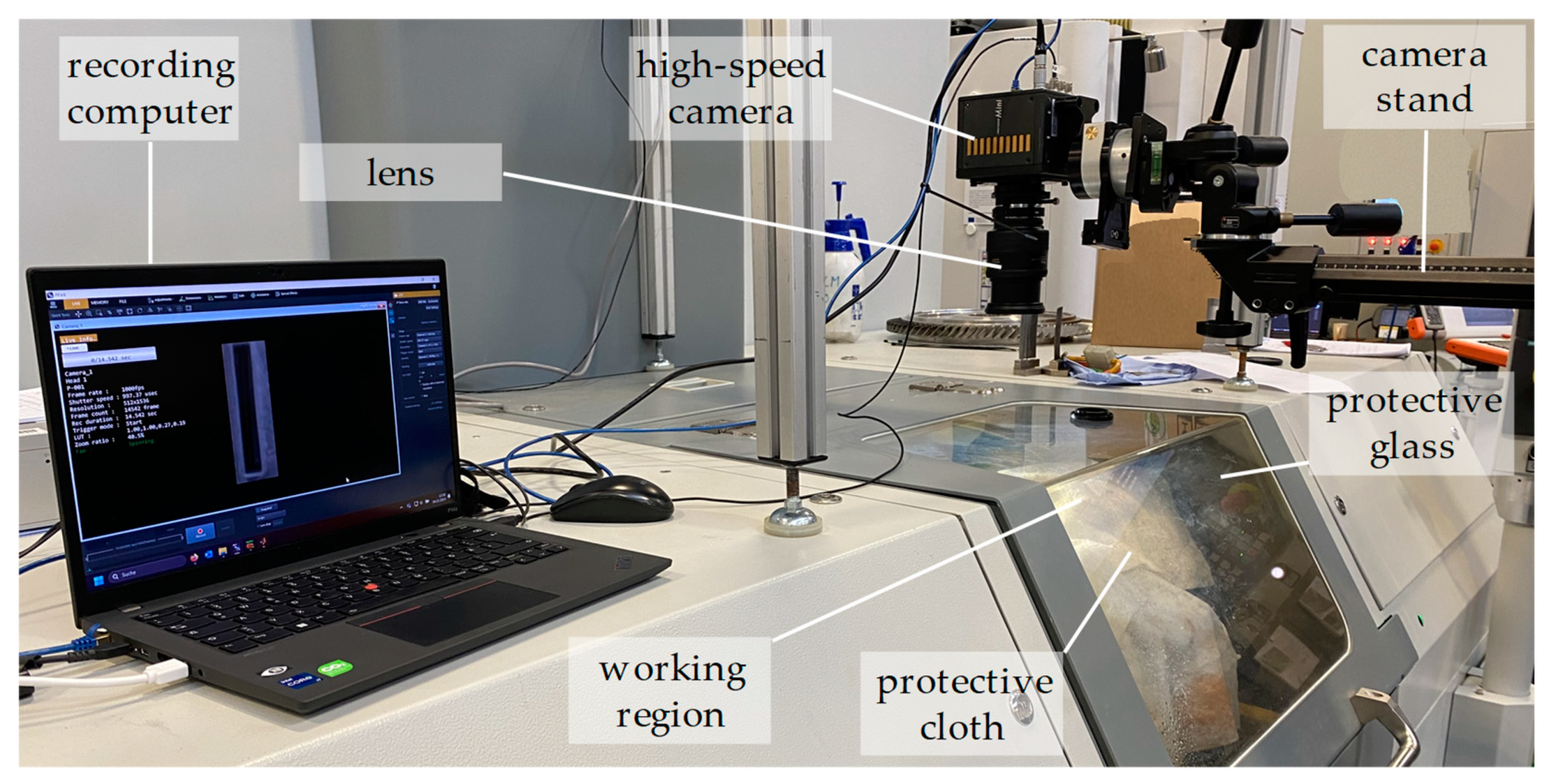
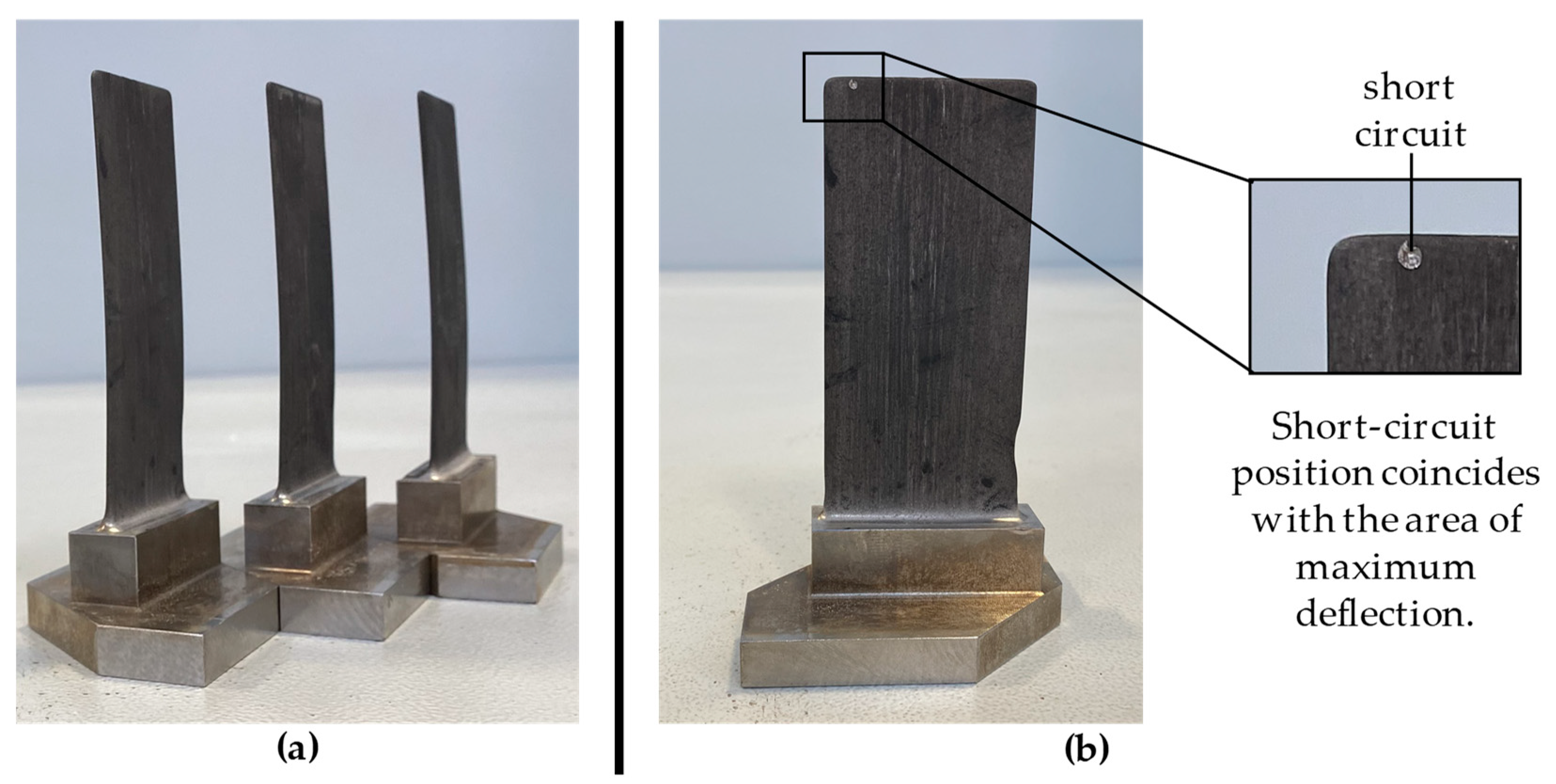
2.1. Reference Blade Geometry and Experimental Setup

From a manufacturing standpoint, high-pressure compressor blades hold particular significance due to their heightened manufacturing complexity when compared to components in other engine subsystems. This complexity arises from the integrated design of the blades and the machining process, which involves a single-piece fabrication. Furthermore, these components exhibit intricate geometry, characterized by long, slender geometries with high twists and varying cross-sections aimed at minimizing weight. Additionally, high-pressure compressor blades often utilize Ni-based alloys, chosen for their superior mechanical strength and thermal resistance. The very desired mechanical strength of these alloys presents challenges for the conventional machining process.
To comprehensively explore the production challenges associated with state-of-the-art aero-engine blade-integrated discs, the Fraunhofer Institute for Production Technology IPT has designed a generic blade geometry through analytical calculations and a literature review [2]. Even though the blade geometry cannot be found in an actual turbine engine, the Institute of Aerodynamics, Aachen (AIA) has investigated the aerodynamic feasibility of the design and therefore validated its realism. However, the twist of the blade and resulting twisted cathodes, along with intricate masks for electrolyte flow, create a tool system that prevents convenient optical access to the blade, rendering optical in situ measurement approaches impractical. Consequently, a blade, as illustrated in Figure 2a, was developed that matches the blade presented by Fricke et al. [2] by size and involves a less pronounced tilt.
The blade blank is machined from a stainless-steel type 1.4305, a readily machinable austenitic steel. The initial thickness of the blade blank was chosen to be tstart = 3 mm and is to be machined to a final thickness of tfinal = 1 mm. The tool geometry is the negative geometry of the final cathode geometry and is machined from a 1.4401 type steel. The tool system consists of a polyoxymethylene (POM) mask with optical access to the working gap during machining and a fitting grip to the PECM machine tool EMAG PO 100 SF. This is shown in Figure 2b. While the two cathodes mounted on the x-axes move toward the anode, the anode remains stationary in the middle. The electrolyte is fed to the cathode on one side where the narrow slit distributes the electrolyte along the tip of the blade. The electrolyte is guided by the cathodes from tip to toe and flushes freely at the root of the blade in the working area of the machine.
A FASTCAM Mini WX100 equipped with a 2048 by 2048 monochrome sensor was used for the video recordings. The videos were recorded at a frame rate of 1000 fps with an exposure time of 997 µs. To optimize the recording process (maximize the recording time and minimize the data writing time to the computer memory), the recording area was limited to 512 by 1536 pixels. To achieve close-up focusing, a 24–85 mm lens was used in conjunction with a 20 mm extension tube positioned between the camera body and the lens. While this configuration allowed for closer focusing, it resulted in a narrow focal plane concentrated at the lateral edge of the blade. The camera was securely mounted on an external stative to eliminate any vibration from the machine tool. With sufficient ambient light, no external light source was required for the shot. A protective cloth was used to reduce electrolyte splash and provide unobstructed optical access to the working gap. The overall setup is shown in Figure 3.

2.2. Experimental Results

2.2.1. Machining Results

Figure 4a shows the machined blades using the above-described tool system. Flow grooves typical to ECM parts can be observed on both surfaces of the workpiece as can be seen in Figure 4b. The flow grooves aligned with the electrolyte flushing direction. Throughout the refinement of the technology applied to the specified blade, instances occurred where the tool contacted the blade as shown in Figure 4b. The consistent factor in these occurrences was the location, always at the tip of the blades. These contacts occurred towards the conclusion of the machining process when the thickness of the workpiece approached its final thickness. The reduced thickness at this stage is characterized by a diminished moment of inertia, resulting in reduced stiffness against excitation forces such as flushing and tool oscillation. It should be mentioned that these contacts necessitate tool reconditioning, which is a characteristic cause of production downtimes in industrial application. Considering the point of contact, it appears evident that it corresponds to the location of maximum deflection of the blade.

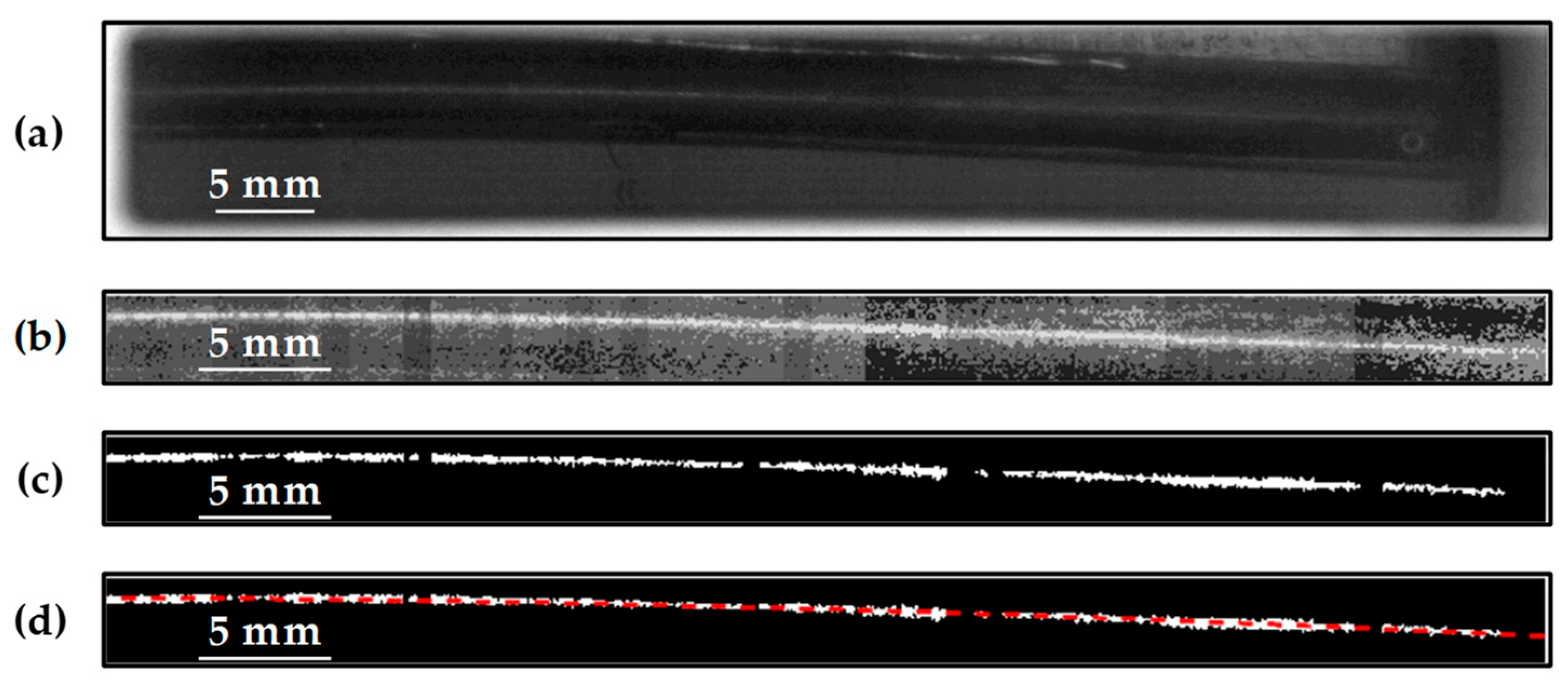
2.2.2. High-Speed Recordings

To better understand and characterize this observation, the high-speed recording setup shown above was employed. Figure 5a shows a frame of the raw image sequence acquired by the high-speed camera with the workpiece at rest, i.e., devoid of any excitation (p = 0 bar, fmech = 0 Hz). As can be seen in the figure, the camera is focused on the frontal edge of the blade, which reflects enough light and hence enables tracking of the workpiece. This approach enables the investigation of lateral deflection while assuming no torsional deflection. Figure 5b–d show the evaluation methodology for a setup with electrolyte flushing pressure p = 8 bar without tool oscillation (fmech = 0 Hz) for a blade of thickness t = 3 mm and working gap s90 = 0.5 mm on each side. The evaluation is carried out using MATLAB (R2023a)®.
After defining a suitable region of interest (ROI) covering the blade and pixel calibration, the frame’s contrast was enhanced. This enhancement was performed segment wise by slicing the ROI into smaller pieces due to the observed variation in light intensity along the length of the blade, caused by reflections from various sources (cf. Figure 5b). Each segment of the ROI was converted to binary using a locally computed threshold to extract the edge of the blade (Figure 5c). The full edge of the blade is then reconstructed and smoothened using a second-order polynomial fitting, represented by the dotted red line on the extracted edge as shown in Figure 5d. By evaluating recordings over 10 s, a maximum deflection of the blade tip was evaluated to be ∆h = 0.3 mm. Given the reduced working gaps of PECM in the range s90 < 0.1 mm, such substantial deflections will inevitably lead to contact between the tool and the workpiece. Figure 6 illustrates the blade tip position over time using the above-described methodology. From the figure, it is evident that electrolyte flow induces a dynamic deflection of the blade. From the observed triangular progression, it becomes apparent that the chosen frame rate of f = 1000 frs should be increased to capture the movement with a higher temporal resolution. This will require incorporating a light source to the setup for an improved illumination of the working over the resulting reduced shutter speed. The reduced shutter speed will also improve the overall image quality and hence mitigate some artefacts such as plateaus observed. By performing fast-Fourier transformations (FFTs), the dominant frequency of the blade tip was found to be ftip ≈ 97.6 Hz.
The above-described tool system and the corresponding machined blades and the evaluation of the workpiece deflection for an exemplary stage are shown as proof of concept. The deflection for various stages can be realized by using similar investigations using the corresponding workpiece thickness. Additionally, the investigations can be extended to workpieces of different heights. Such investigations are necessary to identify critical combinations of flushing parameters with workpiece characteristics.

3. Numerical Investigation of the Workpiece Deflection

3.1. Theoretical Analysis of the Electrolyte Flow

The electrolyte flow in the machining gap is driven by the pressure provided by the ECM machine. This pressure difference relative to ambient pressure is usually set by the operator based on previous experience and adjusted using trial and error to achieve the desired results. The chosen pressure results in a flow rate depending on geometrical properties of the machining gap and material properties of the electrolyte. Since in the traditional process design no focus is put on the flow conditions in the machining gap, the flow rate is not displayed by the machine and cannot be easily measured. The flow rate, however, is the main determining factor of the flow conditions that heavily influence the quality and efficiency of the machining process. The grade of turbulence in the flow depends on the Reynolds number Re, which is defined for channel flow by
R e = ρ   u ¯   H μ
with the fluid density ρ , the mean flow velocity u ¯ , the channel height H and the dynamic viscosity μ . To determine the Reynolds number in the ECM process, the geometry of the machining gap is treated as a steady, fully developed channel flow. Channel flow is defined as a flow between two infinite, parallel walls. Thus, flow-development effects and the influence of the gap edges are ignored in this analysis. This assumption is justified since the aspect ratio of the machining gap is typically very large, in the order of 100 to 10,000. Furthermore, the pressure drop in the electrolyte is assumed to completely occur in the machining gap, corresponding to a frictionless electrolyte delivery to the machining gap. This is justified by the fact that the restriction of the flow is much higher in the machining gap than in the remaining system due to the extremely small flow cross-section in the narrow gap.
A momentum balance of the fluid in the channel yields the following relation between the pressure drop and the counteracting wall shear stresses
p   H T = 2 τ w L T
with the pressure difference Δ p , the wall shear stress τ w , and the channel length L and width T in the flow and the lateral direction. Note that the channel width can be eliminated from this equation. The correlation between the wall shear stress and the Reynolds number depends on the flow state. For laminar flow, an analytical solution for the coefficient of friction C f for channel flows exists [24], p. 264
C f = τ w 1 2 ρ u ¯ 2 = 12 R e  
With this relation, eliminating τ w from the momentum balance (2) and solving for R e yields
R e = Δ p   H 3   ρ 12   L   μ 2
for laminar flow.
For turbulent flow states, the relation between the wall shear stress and the Reynolds number is determined by the friction Reynolds number R e τ and friction velocity u τ
R e τ = ρ   u τ   H 2   μ ,       u τ = τ w / ρ
For turbulent channel flows, an empirical relation between R e τ and R e is given by Pope [24], p. 279 as
R e τ 0.09   R e 0.88
Inserting these relations into the momentum balance (2) and solving for the Reynolds number leads to the following relation for turbulent flows
R e = Δ p   H 3   ρ 0.0648   μ 2   L 1.76
These two relations for the Reynolds number are only valid for either fully laminar or fully turbulent channel flow. Channel flows remain fully laminar for approx. R e < 1380 and fully turbulent for approx. R e > 1800 , while an intermittent regime exists in between [25].
With the provided Equations (4) and (7), the Reynolds number can be determined for the present case. If the flow regime is not known a priori, the applicability of each function can be tested by calculating the Reynolds number and checking if it corresponds to the regime of the relation. For the present geometry, with a machining gap of 0.5 mm on both sides of the blade, and a pressure difference of 8 bar, the laminar relation yields a Reynolds number of 89,605. This means the laminar relation is not applicable. The turbulent relation yields a Reynolds number of 12,654, confirming a fully turbulent flow state. The knowledge of the flow state is an essential prerequisite for numerical simulations of the electrolyte flow for the optimization of the process parameters of the PECM process. With this a priori estimation, appropriate turbulence modeling can be determined, and accurate flow boundary conditions can be applied.

3.2. Numerical Setup

As already mentioned above, besides the study of the electrolyte flow, it is essential to understand the elastostatics of the workpieces in order to better describe their deformation behavior during machining. To this end, the structural properties of the reference blade geometry are investigated using the finite element method (FEM) solver MFEM [26]. This open-source solver supports a wide range of numerical solution methods and mesh types [27]. A second-order FEM discretization is employed in combination with a two-stage, singly diagonal implicit Runge–Kutta (SDIRK) solution method. The blade is discretized by a tetrahedral mesh. A zero-displacement Dirichlet boundary condition is enforced at the blade base surface, while the remaining blade can oscillate freely. For the determination of the eigenfrequencies, a deformed state is specified as an initial condition leaving the blade to oscillate freely. The frequency spectrum of the oscillation is determined by a fast-Fourier transformation (FFT) of the displacement of the blade tip.
In addition to the identification of the blade eigenfrequencies, simulations are conducted that determine the reaction to asymmetric, oscillating pressure distributions of the electrolyte during machining. For these simulations, a perpendicular surface force with sinusoidal temporal distribution is applied to the blade surface. In Figure 7, the simulation mesh of the blade with a thickness of 3 mm is shown. The mesh consists of 86,202 volume elements with an approximate edge length of 1 mm.

3.3. Numerical Results

To better understand the oscillation of the blade during machining, the eigenfrequencies of the blade at different stages of the machining process are determined with numerical simulations. In Figure 8, the frequency spectra of the blade tip displacement for the various blade thicknesses are plotted. The dominant eigenfrequency representing the first mode of oscillation is clearly visible as the maximum with the lowest frequency in the spectrum of each machining stage. These eigenfrequencies are roughly proportional to the remaining blade thickness. This agrees with the analytical formula for the eigenfrequencies of a simple cantilever beam [28]. The main eigenfrequencies range from 273 Hz at 3 mm to 90 Hz at 1 mm for the present case, while typical mechanical oscillation frequencies in the PECM process range from approximately 20 to 50 Hz. This means that no resonant oscillation of the present blade geometry can be expected.
The reaction of the blade to asymmetric pressure distributions in the electrolyte that fluctuate with the mechanical oscillation frequency was determined by simulations as described in Section 3.1. The maximum tip displacement for the different blade thicknesses is plotted as a function of the exciting frequency in Figure 9a. Because the exciting force is kept constant, the thinner blade geometries exhibit a much larger tip displacement due to their lower stiffness. Since the absolute value of the resulting force due to the asymmetric electrolyte force depends on various process parameters and is not known at this stage, a relative comparison of the displacement magnitude is more meaningful than the direct comparison. For this relative comparison, the influence of the different blade stiffnesses is excluded by multiplying the absolute displacement with the moment of inertia of the individual blade geometries. Thus, the resulting relative displacement shows only the influence of oscillation frequency on the blades at the different machining stages.
In Figure 9b, the relative displacement is shown scaled to the displacement of the baseline configuration at the lowest oscillation frequency. The thinner blades also experience a stronger relative displacement and, additionally, show a stronger frequency dependence compared to thicker blades. For the thinnest blade, the displacement at the highest frequency is more than 80% larger than the baseline. This shows that the value of the mechanical oscillation frequency has a large impact on the blade oscillation even for forced oscillation regimes where the frequency does not approach the eigenfrequency of the workpiece.

4. Summary and Outlook

The phenomenon of workpiece deflection in PECM is still an area where scientific understanding is limited due to the lack of suitable experimental methods for its investigation and its physical complexity. Regarding the latter, the already highly challenging problem of PECM modelling needs to be extended to include the structural features of the workpiece. Additionally, there is no deterministic model for selecting the optimal parameters of the process for this manufacturing technology. To fill this gap and develop such a model, knowledge about the relation between flushing parameters and the workpiece deflection is required. To this end, a new tool system was developed that enables optical in situ examination of the working gap. The corresponding generic workpiece is chosen based on next generation blisks. After validation of the tool system through machining processes, optical investigations of the workpiece deflection were carried out. For this purpose, high-speed images of the workpiece were analyzed under the influence of electrolyte flushing. A maximum deflection of the tip of the blade of ∆h = 0.3 mm was recorded. These results clearly show that the workpiece deflection under the influence of various factors, such as electrolyte pressure, can be investigated with high accuracy using in situ optical measurements in PECM, which is the proof of concept.
To further improve the understanding of flushing flow, a theoretical analysis of the electrolyte flow was conducted. For this, the machining gap flow was modeled as a channel flow and formulas for the Reynolds number as a function of the material properties and the flushing pressure were derived for laminar and turbulent flow states. For the present experimental setups, a Reynolds number of 12,654 was calculated, indicating fully turbulent flow in the machining gap. The formulas allow an a priori estimation of the flow properties such as turbulence and mean velocity. The knowledge of these flow properties is essential for the accurate simulation with the appropriate turbulence modeling and the determination of applicable boundary conditions of the electrolyte flow and its interaction with the workpiece structure in real ECM applications.
In the next step, the structure of the present workpiece geometry was simulated using a finite element method. The blade was analyzed for different thicknesses that occur in the course of the machining process. The eigenfrequencies of the different blade configurations were determined and the influence of the mechanical oscillation frequency in the PECM process on the blade deflection was analyzed. It was found that the deflection increases the most for the thinnest blade that has a natural frequency closest to the maximum machining frequency. A maximum of an 80% increase in deflection was found compared to the baseline blade thickness before machining, after correcting for the reduced stiffness due to the decreased thickness. This indicates that the workpiece eigenfrequencies can have a major influence on the optimal process parameters for certain geometries for which the eigenfrequencies approach the mechanical oscillation frequencies of the machining process, even if the eigenfrequencies are not reached.
In the future, experimental investigation using the validated PECM tool system will be carried out with parameter variation to better understand the phenomenon of workpiece deflection due to FSI. The parameters to be varied include the workpiece thickness, the tool oscillation frequency and the flushing pressure. The influence of the working gap arrangement (asymmetrical) is also to be investigated. Knowledge of the influence of these parameters on the workpiece deflection as well as their elastostatics are indispensable in order to develop deterministic models for the selection of machining parameters that either ensure the lowest possible deflection or a defined movement of the blade with scope for compensating the movement (e.g., via electrical machining parameters). Therefore, the presented numerical analyses will be extended to formulate a clear relationship between the stiffness of the workpiece and its dynamic deflection during machining operations. Finally, to enhance the temporal resolution of the optical in situ measurements, the setup will be extended to incorporate an appropriate light source that will permit the recording of the gap phenomena with higher frame rates (>2000 frames per second).

Author Contributions

Conceptualization, E.T.S. and D.L.; methodology, E.T.S., D.L., M.M. and T.P.; software, D.L.; formal analysis, E.T.S. and D.L.; validation, E.T.S. and D.L.; investigation, E.T.S. and D.L.; resources, A.K. and W.S.; data curation, E.T.S. and D.L.; writing—original draft preparation, E.T.S., D.L. and T.P.; writing—review and editing, T.H., M.M., A.K. and W.S.; visualization, D.L. and E.T.S.; supervision, M.M. and T.H.; project administration, A.K. and W.S.; funding acquisition, A.K. and W.S. All authors have read and agreed to the published version of the manuscript.

Funding

The authors would like to thank the German Research Foundation Priority Program SPP2231-FLUSIMPRO “Simulation of the pulsed electrochemical machining (PECM) of thin-walled workpieces for turbomachinery component manufacture—SIMPECT”, project number 439915866, for funding this research.

Data Availability Statement

Data are contained within the article.

Conflicts of Interest

The authors declare no conflicts of interest. The funders had no role in the design of the study; in the collection, analyses, or interpretation of data; in the writing of the manuscript; or in the decision to publish the results.

References

  1. Xu, Z.; Liu, J.; Xu, Q.; Gong, T.; Zhu, D.; Qu, N. The tool design and experiments on electrochemical machining of a blisk using multiple tube electrodes. Int. J. Adv. Manuf. Technol. 2015, 79, 531–539. [Google Scholar] [CrossRef]
  2. Fricke, K.; Gierlings, S.; Ganser, P.; Venek, T.; Bergs, T. Geometry Model and Approach for Future Blisk LCA. IOP Conf. Ser. Mater. Sci. Eng. 2021, 1024, 12067. [Google Scholar] [CrossRef]
  3. Xu, Z.; Wang, Y. Electrochemical machining of complex components of aero-engines: Developments, trends, and technological advances. Chin. J. Aeronaut. 2021, 34, 28–53. [Google Scholar] [CrossRef]
  4. Gardam, G.E. The Removal of Electrodeposits of Nickel from Steel. Trans. IMF 1938, 14, 13–16. [Google Scholar] [CrossRef]
  5. Klocke, F.; Zeis, M.; Klink, A.; Veselovac, D. Technological and Economical Comparison of Roughing Strategies via Milling, EDM and ECM for Titanium- and Nickel-based Blisks. Procedia CIRP 2012, 2, 98–101. [Google Scholar] [CrossRef]
  6. McGeough, J.A. Principles of Electrochemical Machining; Chapman and Hall: London, UK, 1974; ISBN 9780412119705. [Google Scholar]
  7. Rajurkar, K.P.; Zhu, D.; McGeough, J.A.; Kozak, J.; de Silva, A. New Developments in Electro-Chemical Machining. CIRP Ann. 1999, 48, 567–579. [Google Scholar] [CrossRef]
  8. Speidel, A.; Bisterov, I.; Saxena, K.K.; Zubayr, M.; Reynaerts, D.; Natsu, W.; Clare, A.T. Electrochemical jet manufacturing technology: From fundamentals to application. Int. J. Mach. Tools Manuf. 2022, 180, 103931. [Google Scholar] [CrossRef]
  9. Rajurkar, K.P.; Kozak, J.; Wei, B.; McGeough, J.A. Study of Pulse Electrochemical Machining Characteristics. CIRP Ann. 1993, 42, 231–234. [Google Scholar] [CrossRef]
  10. Ebeid, S.J.; Hewidy, M.S.; El-Taweel, T.A.; Youssef, A.H. Towards higher accuracy for ECM hybridized with low-frequency vibrations using the response surface methodology. J. Mater. Process. Technol. 2004, 149, 432–438. [Google Scholar] [CrossRef]
  11. Ernst, A.; Heib, T.; Hall, T.; Schmidt, G.; Bähre, D. Simulation of the Tool Shape Design for the Electrochemical Machining of Jet Engine Vanes. Procedia CIRP 2018, 68, 762–767. [Google Scholar] [CrossRef]
  12. Fujisawa, T.; Inaba, K.; Yamamoto, M.; Kato, D. Multiphysics Simulation of Electrochemical Machining Process for Three-Dimensional Compressor Blade. J. Fluids Eng. 2008, 130, 081602. [Google Scholar] [CrossRef]
  13. van der Velden, T.; Ritzert, S.; Reese, S.; Waimann, J. A novel numerical strategy for modeling the moving boundary value problem of electrochemical machining. Numer. Meth Eng. 2023, 124, 1856–1882. [Google Scholar] [CrossRef]
  14. Zhang, A.; Xu, Z.; Lu, J.; Wang, Y. Improvement of blade platform accuracy in ECM utilizing an auxiliary electrode. Mater. Manuf. Process. 2020, 35, 951–960. [Google Scholar] [CrossRef]
  15. Chen, Y.; Fang, M.; Jiang, L. Multiphysics simulation of the material removal process in pulse electrochemical machining (PECM). Int. J. Adv. Manuf. Technol. 2017, 91, 2455–2464. [Google Scholar] [CrossRef]
  16. Rommes, B.; Lauwers, D.; Herrig, T.; Meinke, M.; Schröder, W.; Klink, A. Concept for the experimental and numerical study of fluid-structure interaction and gas transport in Precise Electrochemical Machining. Procedia CIRP 2021, 102, 204–209. [Google Scholar] [CrossRef]
  17. Jiang, X.; Li, Y.; Li, D.; Xu, Z. Influence of machining gap on both sides of blade in vibration-assisted pulsed electrochemical machining. Int. J. Electrochem. Sci. 2023, 18, 100125. [Google Scholar] [CrossRef]
  18. Saxena, K.K.; Arshad, M.H.; Reynaerts, D.; Kunieda, M. Gas Bubble Evolution during ECM Process can be suppressed by Pulse Parameters: High Speed Videographic Observations during Early Stages of Bubble Evolution. J. Electrochem. Soc. 2023, 170, 83502. [Google Scholar] [CrossRef]
  19. Shimasaki, T.; Kunieda, M. Study on influences of bubbles on ECM gap phenomena using transparent electrode. CIRP Ann. 2016, 65, 225–228. [Google Scholar] [CrossRef]
  20. Saxena, K.; Arshad, M.H.; Reynaerts, D.; Kunieda, M. Effect of pulse parameters on gas bubble evolution during ECM process: Experiments using high-speed videographic observations. In Proceedings of the 19th International Symposium on Electrochemical Machining Technology INSECT 2023 Proceedings, Saarbrücken, Germany, 13–14 November 2022; ZeMA, GmbH: Saarbrücken, Germany, 2023. [Google Scholar]
  21. Tchoupe Sambou, E.; Herrig, T.; Klink, A.; Lauwers, D.; Meinke, M.; Schröder, W. Analysis of bubble evolution in a channel flow with moving walls: An experimental analogy to precise electrochemical machining (PECM). In Proceedings of the 19th International Symposium on Electrochemical Machining Technology INSECT 2023 Proceedings, Saarbrücken, Germany, 13–14 November 2023; ZeMA, GmbH: Saarbrücken, Germany, 2023; pp. 43–49. [Google Scholar]
  22. Tchoupe, E.; Lauwers, D.; Heidemanns, L.; Herrig, T.; Klink, A.; Meinke, M.; Klaas, M.; Schröder, W. Optical in Situ Analysis of Gas Bubble Evolution in Electrochemical Machining Based on Similarity Theory Using Particle Image Velocimetry. Procedia CIRP 2023, 117, 257–262. [Google Scholar] [CrossRef]
  23. Klink, A.; Heidemanns, L.; Rommes, B. Study of the electrolyte flow at narrow openings during electrochemical machining. CIRP Ann. 2020, 69, 157–160. [Google Scholar] [CrossRef]
  24. Pope, S.B. Turbulent Flows; Cambridge University Press: Cambridge, UK, 2000; ISBN 9780521598866. [Google Scholar]
  25. Patel, V.C.; Head, M.R. Some observations on skin friction and velocity profiles in fully developed pipe and channel flows. J. Fluid Mech. 1969, 38, 181–201. [Google Scholar] [CrossRef]
  26. Kolev, T.; Dobrev, V. Modular Finite Element Methods (MFEM); Lawrence Livermore National Laboratory (LLNL): Livermore, CA, USA, 2010. [Google Scholar]
  27. Anderson, R.; Andrej, J.; Barker, A.; Bramwell, J.; Camier, J.-S.; Cerveny, J.; Dobrev, V.; Dudouit, Y.; Fisher, A.; Kolev, T.; et al. MFEM: A modular finite element methods library. Comput. Math. Appl. 2021, 81, 42–74. [Google Scholar] [CrossRef]
  28. Mukhopadhyay, M. Structural Dynamics; Springer International Publishing: Cham, Switzerland, 2021; ISBN 978-3-030-69673-3. [Google Scholar]
Figure 1. Concept of the decision model for precise electrochemical machining as proposed by Rommes et al. [17].
Jmmp 08 00138 g001
Figure 2. (a) Geometry of the conceived blade considered for the current investigation and (b) tool, workpiece and electrolyte mask arrangement with optical access for optical in situ measurements.
Jmmp 08 00138 g002
Figure 3. Image depicting the experimental setup on EMAG PO 100 SF alongside the high-speed recording setup.
Jmmp 08 00138 g003
Figure 4. (a) Machined blades with a final thickness of t = 1 mm and (b) instances of short circuits and their location.
Jmmp 08 00138 g004
Figure 5. (a) Configuration of the blade at rest position, (b) representation of the extracted blade edge, (c) extracted blade edge and (d) blade edge as red dotted line after reconstruction and smoothing.
Jmmp 08 00138 g005
Figure 6. Movement of the blade tip over time for a blade thickness of t = 3 mm, flushing pressure of p = 8 bar and no tool oscillation.
Jmmp 08 00138 g006
Figure 7. Tetrahedral simulation mesh for the blade with a thickness of 3 mm.
Jmmp 08 00138 g007
Figure 8. Frequency spectrum of the blade for three thicknesses. The shaded area marks the typical mechanical PECM frequencies of 20 to 50 Hz.
Jmmp 08 00138 g008
Figure 9. (a) Maximum absolute deflection of the blade at three thicknesses under cyclical load in the range of 20 to 50 Hz. (b) Relative maximum deflection of the blade scaled to the baseline configuration.
Jmmp 08 00138 g009
Disclaimer/Publisher’s Note: The statements, opinions and data contained in all publications are solely those of the individual author(s) and contributor(s) and not of MDPI and/or the editor(s). MDPI and/or the editor(s) disclaim responsibility for any injury to people or property resulting from any ideas, methods, instructions or products referred to in the content.

