

Shape Memory Polymers in 4D Printing: Investigating Multi-Material Lattice Structures


Abstract
1. Introduction
1.1. Four-Dimensional Printing
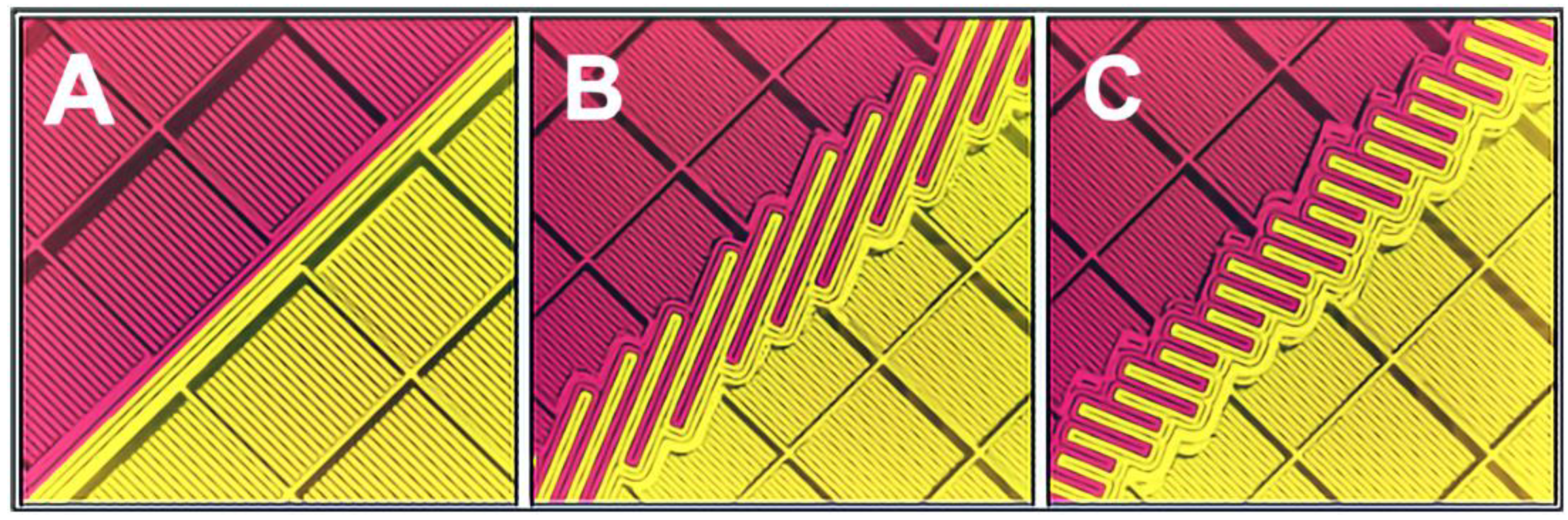
1.2. Interlocking Lattice Structures
1.3. Novelty and Significance
- What are the chemical, thermal, and mechanical properties of SMP TPU? It is important to characterize these properties before attempting to create ITIL due to the following two reasons: (a) to ensure that a regular 3D printer can be used to extrude an SMP TPU filament, and (b) to ensure that the properties of this material is compatible with that of PLA so that the properties of the ITIL are not compromised.
- What material properties of SMP TPU influence the shape memory characteristics of the printed samples? It is important to understand this as this characterization will dictate how the ITIL structure behaves.
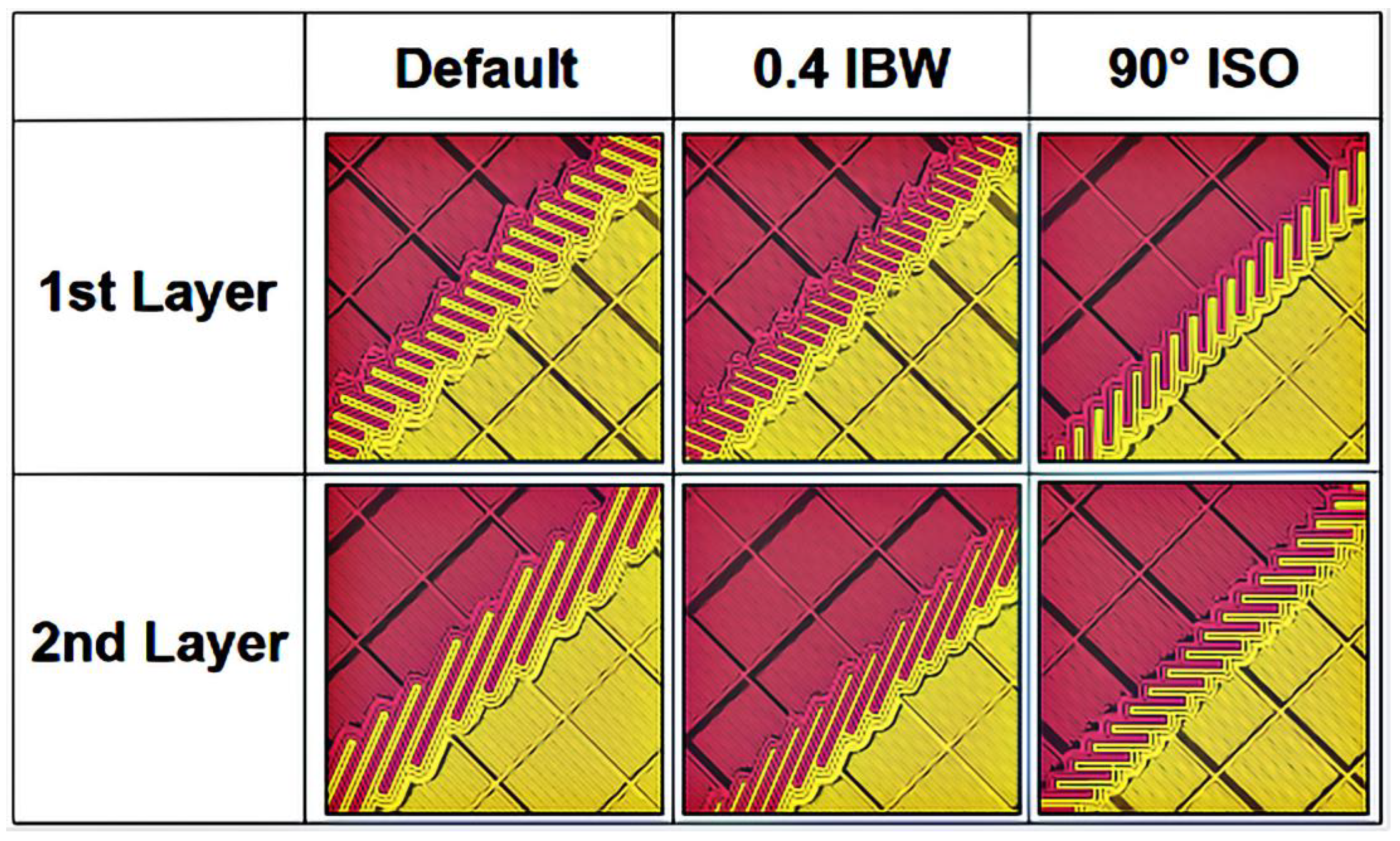
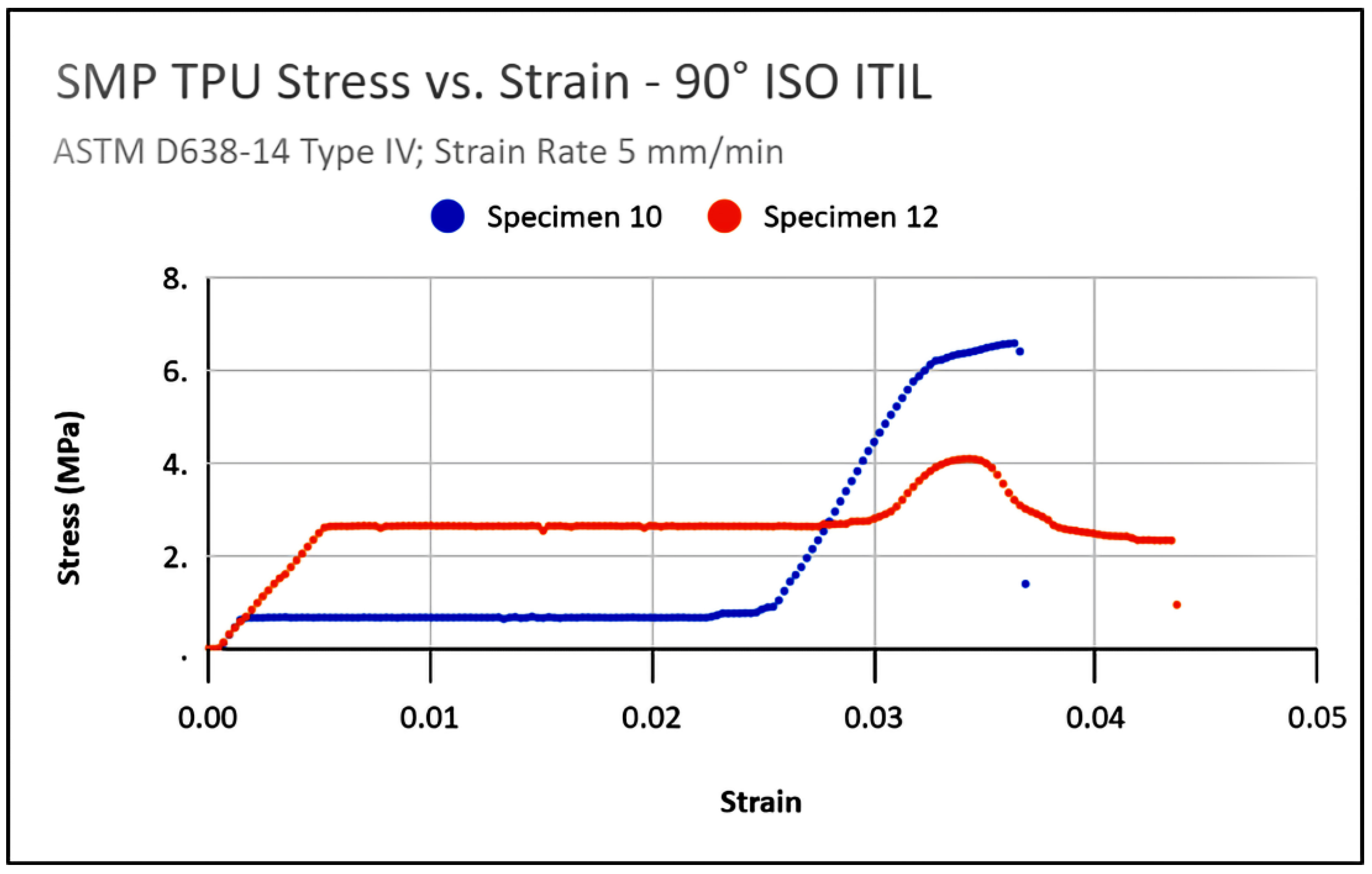
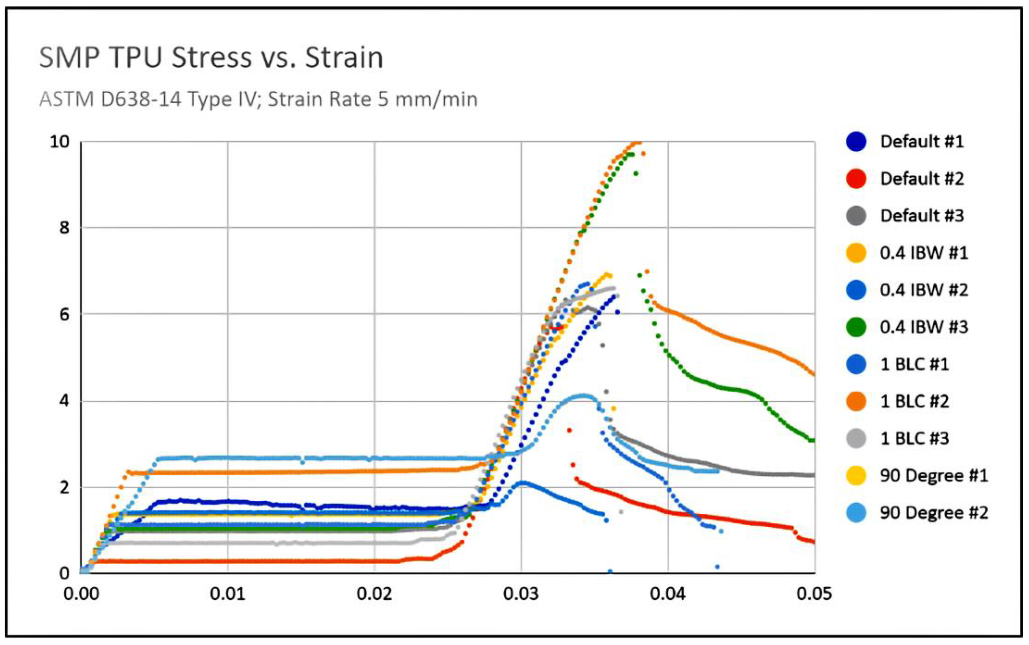
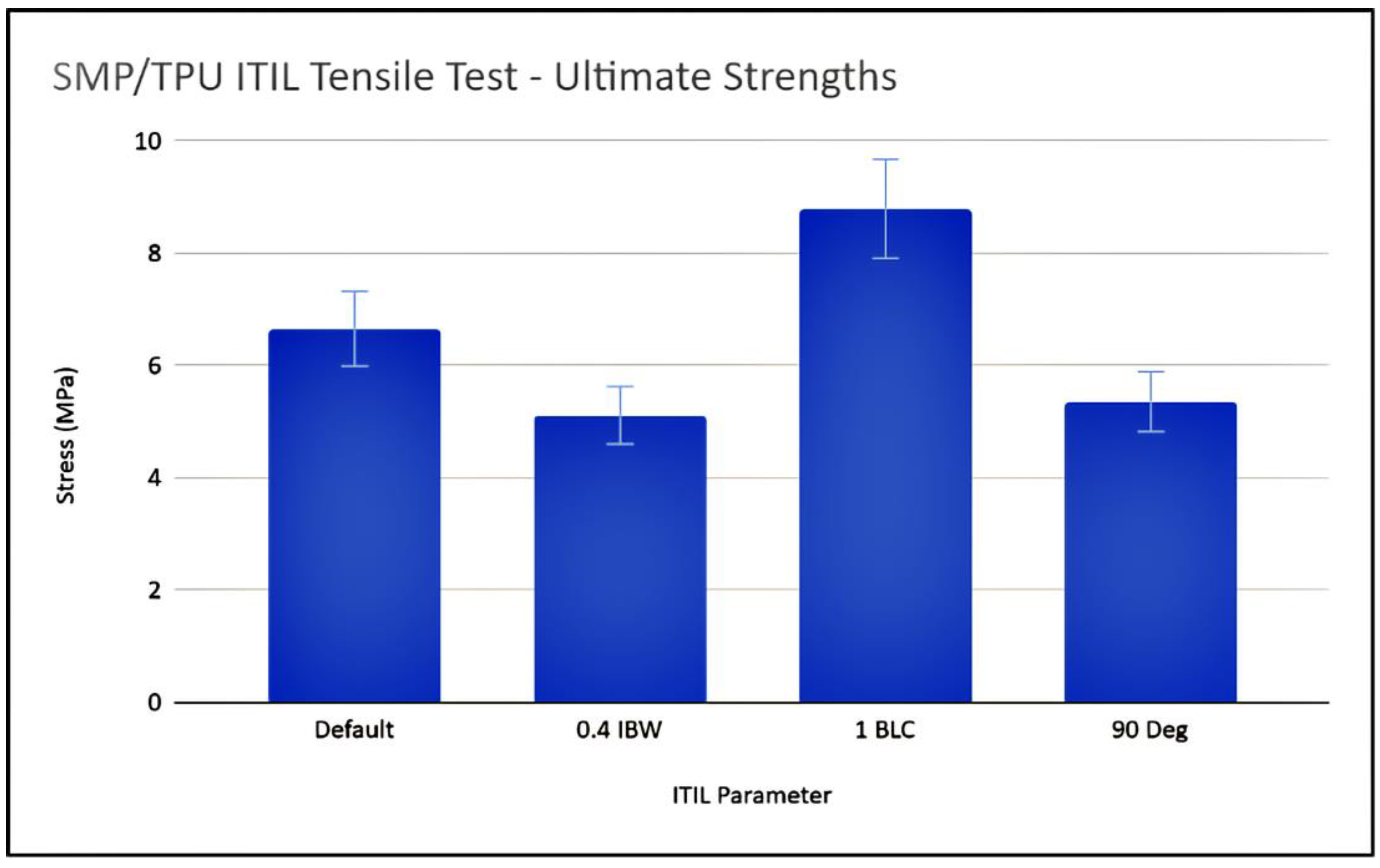
- What are the tensile and ultimate strengths of the parts printed using the ITIL technique with SMP TPU and PLA? How are these strengths affected by various slicer parameters?
2. Materials and Methods
2.1. Material Selection
2.2. Chemical Characterization
2.3. Thermal Characterization
2.4. Tensile Testing
3. Results and Discussion
3.1. Characterization of the SMP TPU
3.1.1. Chemical Characterization
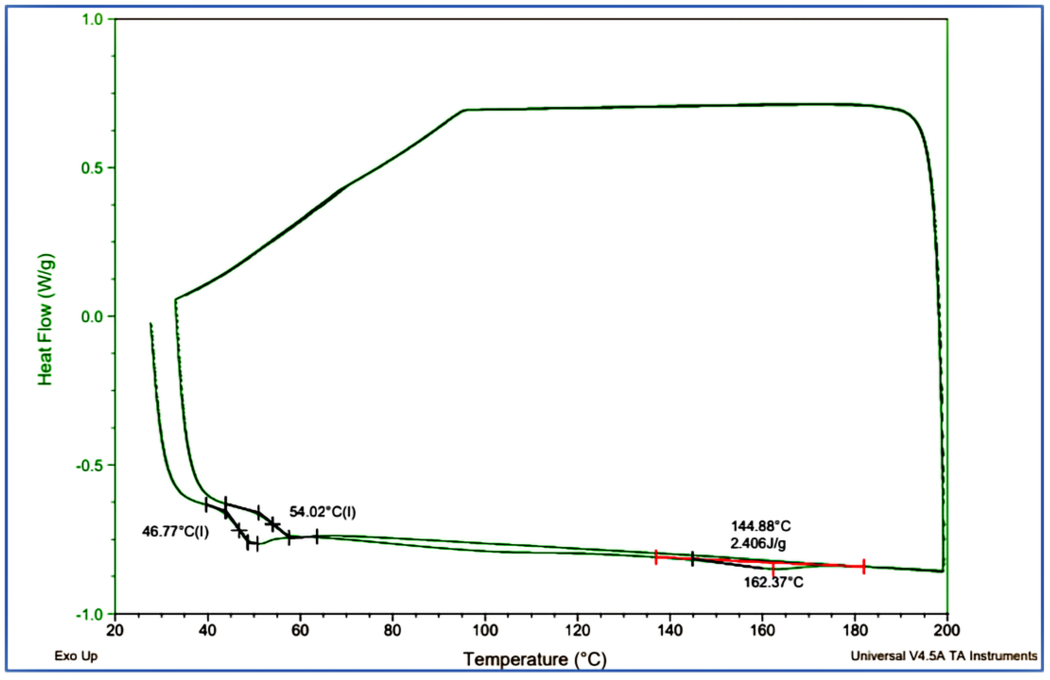
3.1.2. Differential Scanning Calorimetry (DSC)
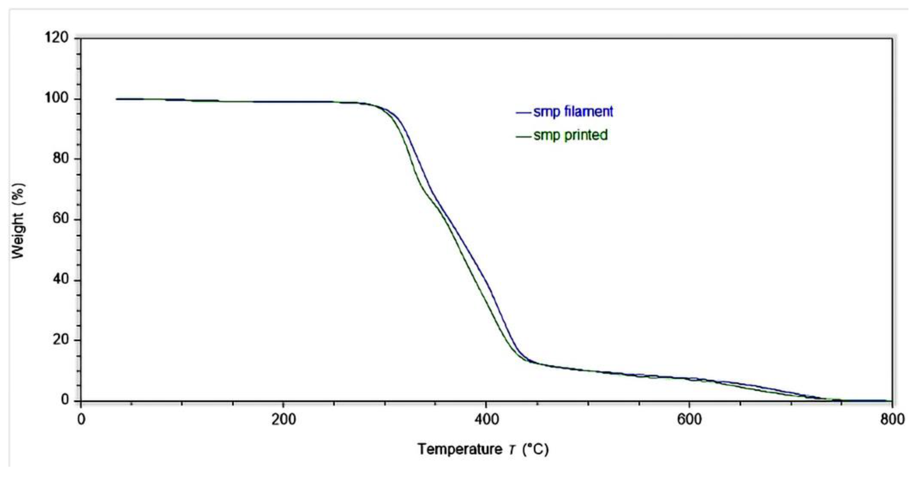
3.1.3. Thermogravimetric Analysis (TGA)
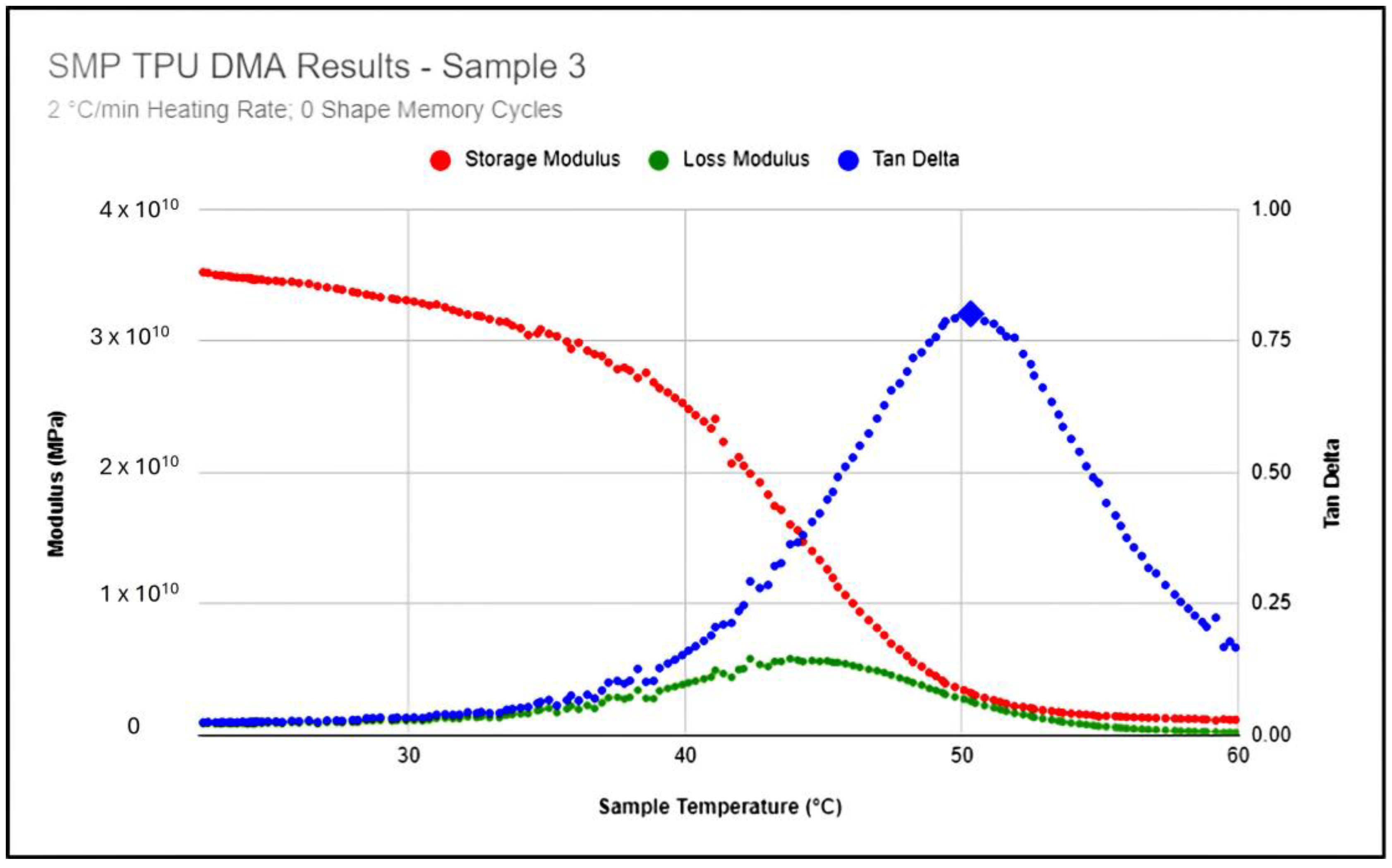
3.2. Dynamic Mechanical Analysis (DMA)
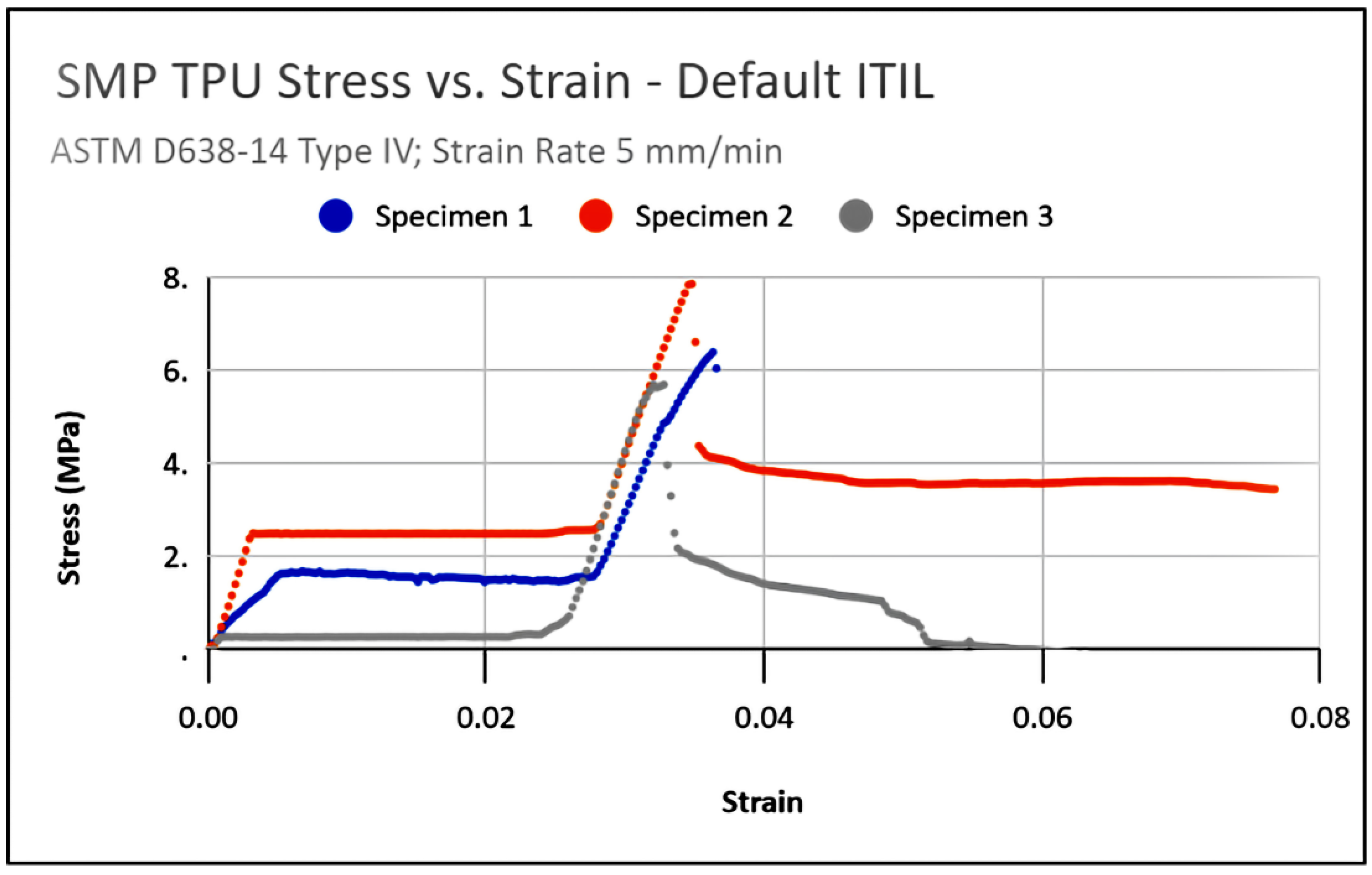
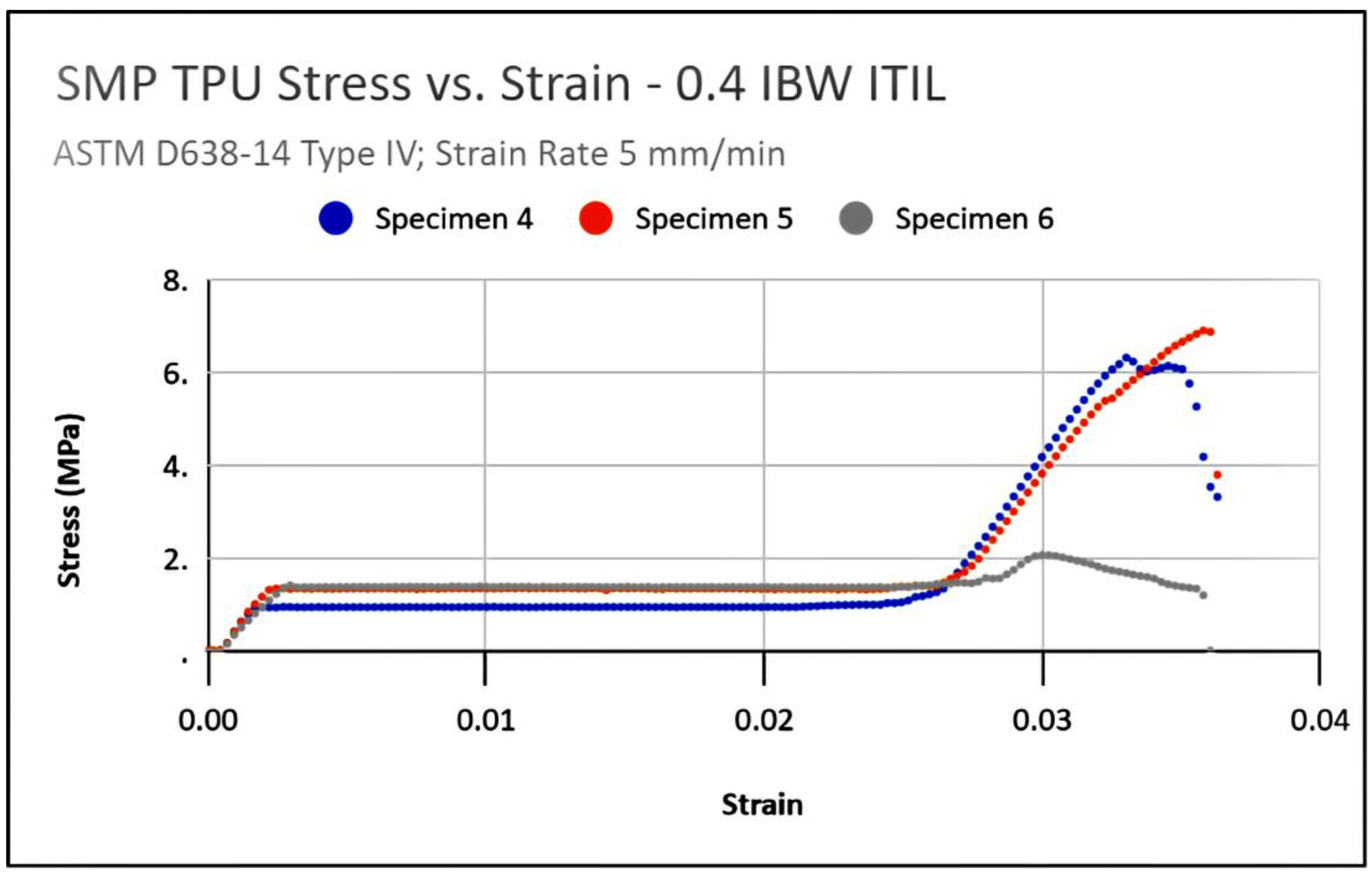
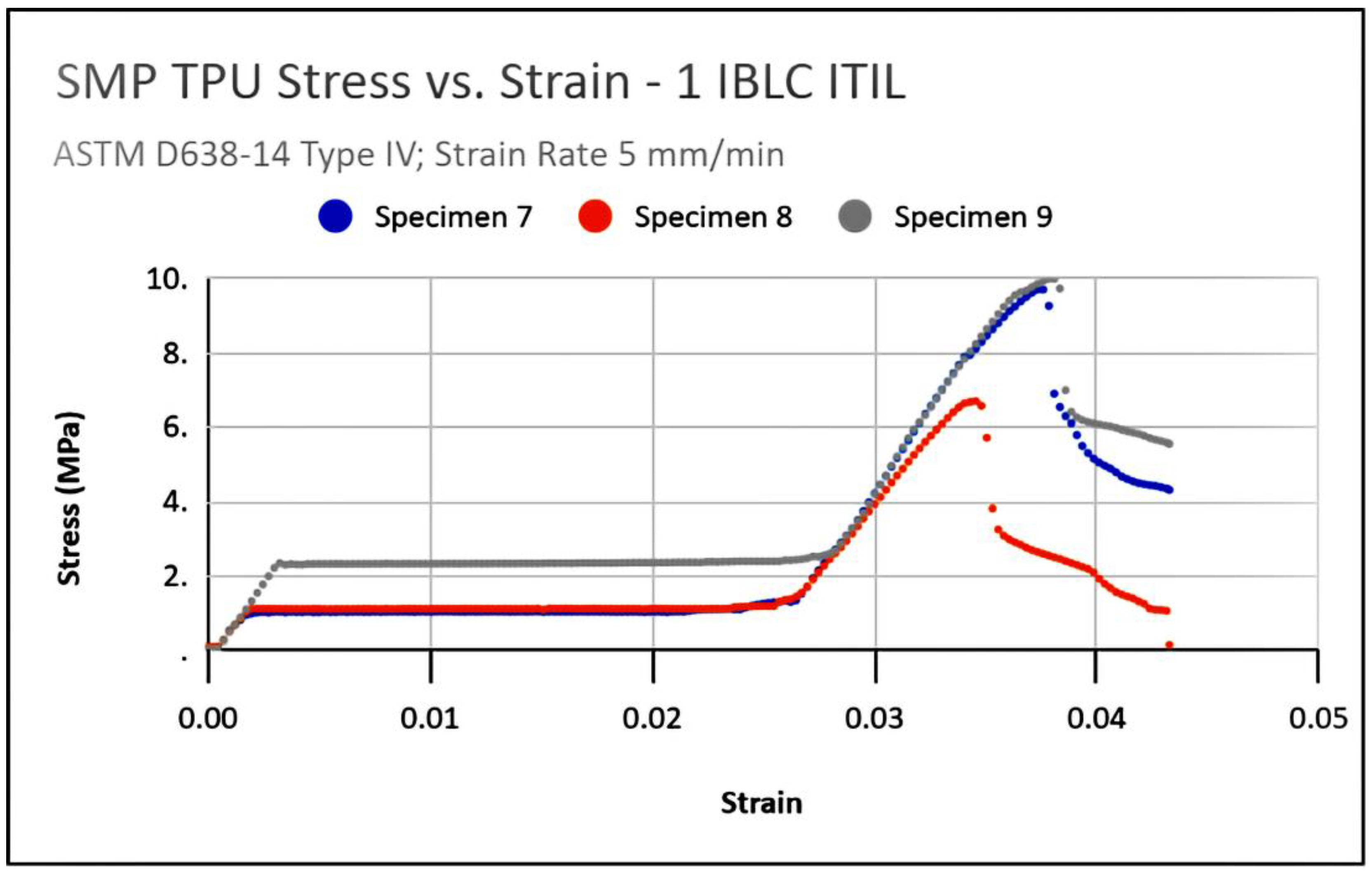
3.3. Interlocking Lattice Tensile Testing
4. Discussion
4.1. Classification of the Shape Change Effect
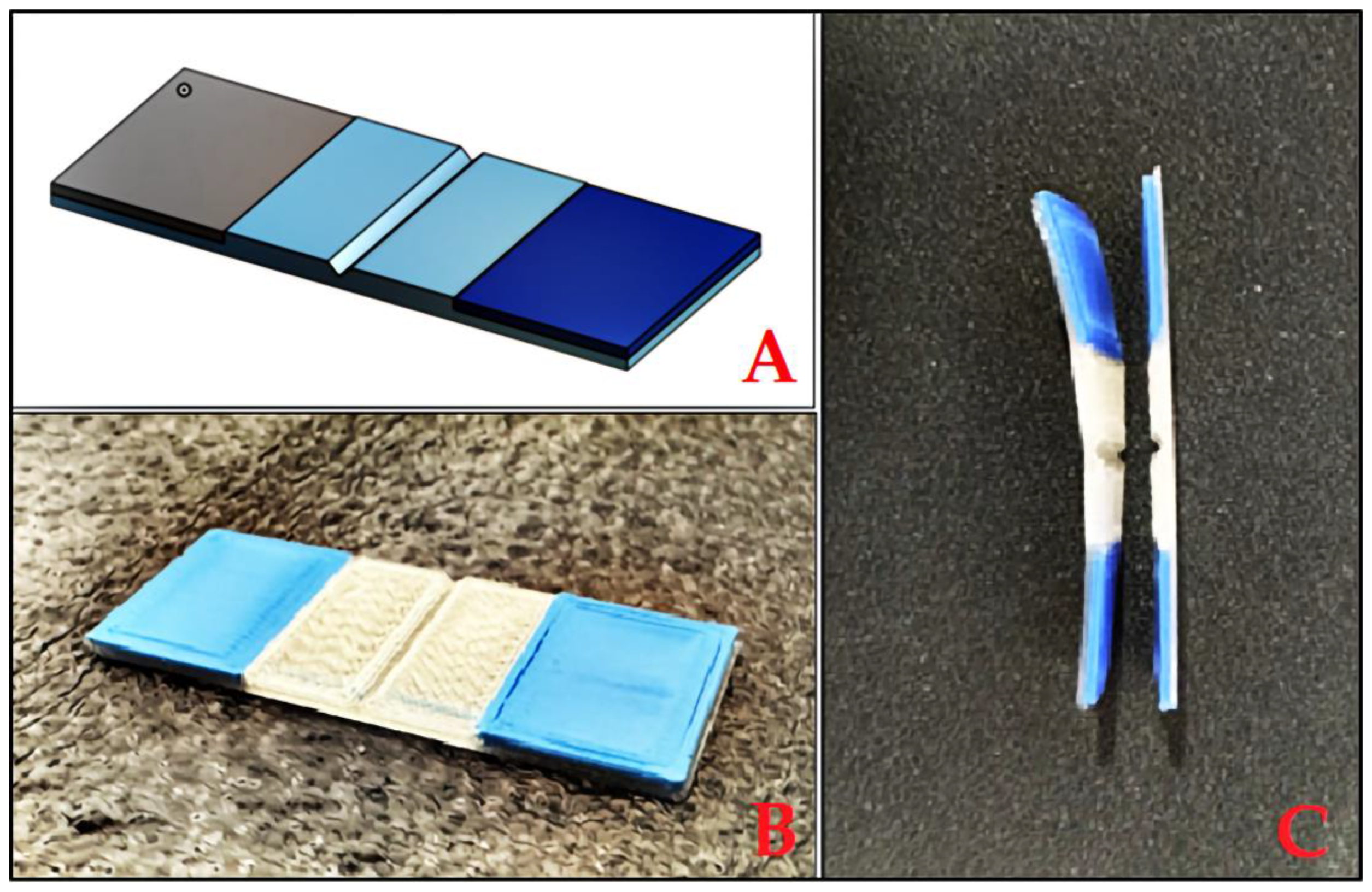
4.2. Creation of Multi-Material Parts
4.3. Linking DMA Results to Macroscopic Behavior
4.4. Challenges and Limitations
5. Conclusions
Supplementary Materials
Author Contributions
Funding
Institutional Review Board Statement
Informed Consent Statement
Data Availability Statement
Acknowledgments
Conflicts of Interest
References
- Skylar Tibbits. Self-Assembly Lab. Available online: https://selfassemblylab.mit.edu/skylar-tibbits (accessed on 5 December 2023).
- 4D Printing. Self-Assembly Lab. Available online: https://selfassemblylab.mit.edu/4d-printing (accessed on 5 December 2023).
- Lefebvre, E.; Faucheu, J.; Del Curto, B.; Delafosse, D. Stimuli-Responsive Materials: Definition, Classification and Descriptions. In Proceedings of the 7th International Materials Education Symposium, Cambridge, UK, 3–5 April 2015. [Google Scholar]
- Lee, A.Y.; An, J.; Chua, C.K. Two-Way 4D Printing: A Review on the Reversibility of 3D-Printed Shape Memory Materials. Engineering 2017, 3, 663–674. [Google Scholar] [CrossRef]
- Sun, L.; Huang, W.M.; Ding, Z.; Zhao, Y.; Wang, C.C.; Purnawali, H.; Tang, C. Stimulus-Responsive Shape Memory Materials: A Review. Mater. Des. 2012, 33, 577–640. [Google Scholar] [CrossRef]
- Hu, J.; Zhu, Y.; Huang, H.; Lu, J. Recent Advances in Shape–Memory Polymers: Structure, Mechanism, Functionality, Modeling and Applications. Prog. Polym. Sci. 2012, 37, 1720–1763. [Google Scholar] [CrossRef]
- Hager, M.D.; Bode, S.; Weber, C.; Schubert, U.S. Shape Memory Polymers: Past, Present and Future Developments. Prog. Polym. Sci. 2015, 49–50, 3–33. [Google Scholar] [CrossRef]
- Mulakkal, M.C.; Trask, R.S.; Ting, V.P.; Seddon, A.M. Responsive Cellulose-Hydrogel Composite Ink for 4D Printing. Mater. Des. 2018, 160, 108–118. [Google Scholar] [CrossRef]
- Akbari, S.; Sakhaei, A.H.; Kowsari, K.; Yang, B.; Serjouei, A.; Yuanfang, Z.; Ge, Q. Enhanced Multimaterial 4D Printing with Active Hinges. Smart Mater. Struct. 2018, 27, 065027. [Google Scholar] [CrossRef]
- Aldawood, F.K. A Comprehensive Review of 4D Printing: State of the Arts, Opportunities, and Challenges. Actuators 2023, 12, 101. [Google Scholar] [CrossRef]
- Support Community. support.makerbot.com. 24 May 2023. Available online: https://support.makerbot.com/s/article/1667410778895 (accessed on 8 December 2023).
- Kuipers, T.; Su, R.; Wu, J.; Wang, C.C. ITIL: Interlaced Topologically Interlocking Lattice for continuous dual-material extrusion. Addit. Manuf. 2022, 50, 102495. [Google Scholar] [CrossRef]
- Aharoni, L.; Bachelet, I.; Carstensen, J.V. Topology Optimization of Rigid Interlocking Assemblies. Comput. Struct. 2021, 250, 106521. [Google Scholar] [CrossRef]
- Schaller, C. 4.9: Modulus, Temperature, Time. Chemistry LibreTexts. 6 October 2019. Available online: https://chem.libretexts.org/Bookshelves/Organic_Chemistry/Polymer_Chemistry_(Schaller)/04%3A_Polymer_Properties/4.09%3A_Modulus_Temperature_Time (accessed on 14 December 2023).
- TPU SMP—4D Filament. Available online: https://filament2print.com/gb/flexible-tpe-tpu/1656-tpu-smp-4d-filament.html (accessed on 24 September 2023).
- Electromechanical Testing Systems. Instron. Available online: https://www.instron.com/en/products/testing-systems/out-of-production-systems/electromechanical (accessed on 21 December 2023).
- Standard Test Method for Tensile Properties of Plastics. ASTM International. 2015. Available online: https://www.astm.org/d0638-14.html (accessed on 21 December 2023).
- Park, S.; Moon, J.; Cho, M.; Lee, Y.S.; Chung, H.; Yang, S. Multiscale Study of Shape-Memory Behavior of Semicrystalline Polyurethane Nanocomposites Doped with Silica Nanoparticles Based on Coarse-Grained Molecular Dynamics Simulation. ACS Appl. Polym. Mater. 2024, 6, 3192–3206. [Google Scholar] [CrossRef]
- Wang, Y.; Zhu, M.; Hao, C.; Dai, R.; Huang, M.; Liu, H.; He, S.; Liu, W. Development of Semi-Crystalline Polyurethane with Self-Healing and Body Temperature-Responsive Shape Memory Properties. Eur. Polym. J. 2022, 167, 111060. [Google Scholar] [CrossRef]
- Nissenbaum, A.; Greenfeld, I.; Wagner, H.D. Shape Memory Polyurethane—Amorphous Molecular Mechanism during Fixation and Recovery. Polymer 2020, 190, 122226. [Google Scholar] [CrossRef]
- Dayyoub, T.; Maksimkin, A.V.; Filippova, O.V.; Tcherdyntsev, V.V.; Telyshev, D.V. Shape Memory Polymers as Smart Materials: A Review. Polymers 2022, 14, 3511. [Google Scholar] [CrossRef] [PubMed]
- Scalet, G. Two-Way and Multiple-Way Shape Memory Polymers for Soft Robotics: An Overview. Actuators 2020, 9, 10. [Google Scholar] [CrossRef]
- Slavkovic, V.; Palic, N.; Milenkovic, S.; Zivic, F.; Grujovic, N. Thermo-Mechanical Characterization of 4D-Printed Biodegradable Shape-Memory Scaffolds Using Four-Axis 3D-Printing System. Materials 2023, 16, 5186. [Google Scholar] [CrossRef] [PubMed]
- Mendenhall, R.; Eslami, B. Experimental Investigation on Effect of Temperature on FDM 3D Printing Polymers: ABS, PETG, and PLA. Appl. Sci. 2023, 13, 11503. [Google Scholar] [CrossRef]
- Rahmatabadi, D.; Soltanmohammadi, K.; Aberoumand, M.; Soleyman, E.; Ghasemi, I.; Baniassadi, M.; Abrinia, K.; Bodaghi, M.; Baghani, M. 4D printing of porous PLA-TPU structures: Effect of applied deformation, loading mode and infill pattern on the shape memory performance. Phys. Scr. 2024, 99, 025013. [Google Scholar] [CrossRef]
- Zolfaghari, A.; Purrouhani, M.R.; Zolfagharian, A. A response surface methodology study on 4D printing for layered PLA/TPU structures. Prog. Addit. Manuf. 2024, 1–12. [Google Scholar] [CrossRef]
- Santiago, D.; Fabregat-Sanjuan, A.; Ferrando, F.; De la Flor, S. Improving of Mechanical and Shape-Memory Properties in Hyperbranched Epoxy Shape-Memory Polymers. Shape Mem. Superelasticity 2016, 2, 239–246. [Google Scholar] [CrossRef]
- Yu, K.; Ge, Q.; Qi, H. Reduced time as a unified parameter determining fixity and free recovery of shape memory polymers. Nat. Commun. 2014, 5, 3066. [Google Scholar] [CrossRef] [PubMed]


| Slicer Parameter | Value |
|---|---|
| Layer height | 0.2 mm |
| Infill percentage | 10% |
| Nozzle temperature | 215 °C |
| Bed temperature | 30 °C |
| Print speed | 30 mm/s |
| Sample Number | ITIL Parameter | Value |
|---|---|---|
| 1 | All (IBW, ISO, IBLC) | Default (0.8 mm, 2, 22.5°) |
| 2 | ||
| 3 | ||
| 4 | Interlocking Beam Width | 0.4 mm |
| 5 | ||
| 6 | ||
| 7 | Interlocking Beam Layer Count | 1 |
| 8 | ||
| 9 | ||
| 10 | Interlocking Structure Orientation | 90° |
| 11 | ||
| 12 |
| Sample # | Heating Rate (°C/min) | # Shape Memory Cycles | Average Tg (°C) |
|---|---|---|---|
| 1–3 | 2 | 0 | 51.43 |
| 4–6 | 5 | 0 | 50.59 |
| 7–9 | 5 | 5 | 48.84 |
| 10–12 | 2 | 10 | 50.80 |
| Sample | Storage Modulus at 25 °C (GPa) | Loss Modulus Peak (MPa) | Glass Transition Temp Tg | Storage Modulus at Tg + 5 °C (GPa) |
|---|---|---|---|---|
| 1 | 33.7 | 5774 | 51.24 | 1.26 |
| 2 | 32.1 | 5575 | 50.99 | 1.40 |
| 3 | 34.6 | 5826 | 50.33 | 1.46 |
| 4 | 35.5 | 6523 | 52.15 | 1.71 |
| 5 | 35.3 | 6514 | 50.78 | 2.03 |
| 6 | 33.7 | 6668 | 50.80 | 1.94 |
| 7 | 30.3 | 5400 | 48.93 | 1.05 |
| 8 | 31.3 | 5550 | 48.24 | 1.12 |
| 9 | 38.2 | 7160 | 49.36 | 1.29 |
| 10 | 55.2 | 8570 | 51.36 | 0.787 |
| 11 | 45.0 | 8370 | 52.35 | 0.407 |
| 12 | 33.1 | 6170 | 51.63 | 0.361 |
| Samples | Parameter | Average Ultimate Strength (MPa) | Maximum Ultimate Strength (MPa) | % of SMP TPU Ultimate Strength (Avg/Max) |
|---|---|---|---|---|
| 1–3 | Default | 6.66 | 7.87 | 42/49 |
| 4–6 | IBW | 5.12 | 6.92 | 32/43 |
| 7–9 | IBLC | 8.80 | 9.99 | 55/62 |
| 10–12 | ISO | 5.36 | 6.60 | 34/41 |
Disclaimer/Publisher’s Note: The statements, opinions and data contained in all publications are solely those of the individual author(s) and contributor(s) and not of MDPI and/or the editor(s). MDPI and/or the editor(s) disclaim responsibility for any injury to people or property resulting from any ideas, methods, instructions or products referred to in the content. |
© 2024 by the authors. Licensee MDPI, Basel, Switzerland. This article is an open access article distributed under the terms and conditions of the Creative Commons Attribution (CC BY) license (https://creativecommons.org/licenses/by/4.0/).
Share and Cite
Pokras, D.; Schneider, Y.; Zaidi, S.; Viswanathan, V.K. Shape Memory Polymers in 4D Printing: Investigating Multi-Material Lattice Structures. J. Manuf. Mater. Process. 2024, 8, 154. https://doi.org/10.3390/jmmp8040154
Pokras D, Schneider Y, Zaidi S, Viswanathan VK. Shape Memory Polymers in 4D Printing: Investigating Multi-Material Lattice Structures. Journal of Manufacturing and Materials Processing. 2024; 8(4):154. https://doi.org/10.3390/jmmp8040154
Chicago/Turabian StylePokras, David, Yanika Schneider, Sohail Zaidi, and Vimal K. Viswanathan. 2024. "Shape Memory Polymers in 4D Printing: Investigating Multi-Material Lattice Structures" Journal of Manufacturing and Materials Processing 8, no. 4: 154. https://doi.org/10.3390/jmmp8040154
APA StylePokras, D., Schneider, Y., Zaidi, S., & Viswanathan, V. K. (2024). Shape Memory Polymers in 4D Printing: Investigating Multi-Material Lattice Structures. Journal of Manufacturing and Materials Processing, 8(4), 154. https://doi.org/10.3390/jmmp8040154