Article

Formability Assessment of Additively Manufactured Materials via Dieless Nakajima Testing

by
Rui F. V. Sampaio
1,
Pedro M. S. Rosado
1,
João P. M. Pragana
1,
Ivo M. F. Bragança
1,2,
Carlos M. A. Silva
1,
Luís G. Rosa
1 and
Paulo A. F. Martins
1,*
1
IDMEC, Instituto Superior Técnico, Universidade de Lisboa, 1049-001 Lisbon, Portugal
2
CIMOSM, Instituto Superior de Engenharia de Lisboa, Instituto Politécnico de Lisboa, 1959-007 Lisbon, Portugal
*
Author to whom correspondence should be addressed.
J. Manuf. Mater. Process. 2024, 8(4), 180; https://doi.org/10.3390/jmmp8040180
Submission received: 29 July 2024 / Revised: 15 August 2024 / Accepted: 17 August 2024 / Published: 18 August 2024

Abstract

:
This paper delves into the formability of material deposited by wire arc additive manufacturing. It presents a novel dieless Nakajima testing procedure that offers a practical solution for obtaining strain loading paths up to failure directly from the deposited material without the need for extracting sheet blanks. The procedure involved machining a region of the deposited material to the desired shape and thickness and using a press to drive and control the movement of a hemispherical punch. The test was designed using finite element modeling, and its effectiveness in obtaining the required strain loading paths directly from the deposited material was verified through experimentation with digital image correlation. Importantly, this novel test eliminates the need for the special-purpose tool setup required in conventional Nakajima sheet formability tests, thereby simplifying the overall testing process.

1. Introduction

The manufacturing industry faces growing demands for customized, flexible, high-quality parts with increasingly complex geometries to swiftly meet consumer preferences and market trends. Concurrently, rising industrial competition urges cost efficiency, whereas increasing sustainability awareness emphasizes the need to reduce material waste, minimize energy consumption, and comply with environmental regulations.
In recent years, researchers have been actively exploring new technologies, such as metal additive manufacturing, into production lines to keep pace with the advancements and innovations required to address the demands and challenges mentioned above. Efforts have been directed toward overcoming technical barriers and ensuring compatibility between traditional and metal additive manufacturing processes.
The hybridization of metal additive manufacturing (MAM) with metal forming is an excellent example of these ongoing efforts, as it aims to combine the advantages of both technologies to create high-quality, eco-friendly parts with complex designs [1]. Recent publications underscore the use of MAM to introduce reinforcements [2] and functional elements [3] in metal forming products, which would have been very difficult or impossible to obtain through traditional forming processes alone.
Alternatively, MAM has also been used to produce preforms that are subsequently subjected to traditional sheet [4], bulk [5], and sheet–bulk [6] forming processes to fabricate net-shaped or near-net-shaped parts in small to medium batch sizes.
However, certain publications have highlighted the challenges of anisotropy and formability limits [7,8] due to metallurgical phenomena, which confine the hybridization of MAM with metal forming to low levels of plastic deformation. Before focusing on these constraints, which justify the developments presented in this paper, it is essential to explain why the work is performed using wire arc additive manufacturing (WAAM) rather than other MAM processes (Figure 1).
The first reason is that WAAM, a type of wire direct energy deposition (wire-DED) process, has a low capital investment requirement. It uses an electric arc to supply the thermal energy needed for melting and depositing the wire feedstock material layer by layer and operates on the same principles as the well-established gas metal arc, gas tungsten arc, and plasma arc welding processes [9]. Secondly, arc welding machines and motion systems are widely available in metalworking companies, enhancing the appeal of WAAM [10]. Lastly, WAAM is effective for producing large-scale parts with low to medium quality, thanks to its material efficiency and high deposition rates (5–6 kg/h) compared to other MAM processes that rely on laser or electron beam thermal heat sources [11,12].
However, despite these advantages, WAAM still needs to become a viable alternative manufacturing technology in many industries due to difficulties meeting parts’ geometrical, surface, and metallurgical requirements. These challenges are primarily due to the large melt pools created by the electric arc, which cause differential expansion and contraction across the deposited material during heating and cooling cycles, as well as issues such as porosity, precipitation reactions, and the formation of dendritic-based columnar grain structures [13]. In addition, thermal residual stresses after the material cools to ambient temperature give rise to distortions that further reduce the overall accuracy of the as-built parts [14].
The hybridization of WAAM with metal forming has mainly been used to enhance the microstructure, reduce porosity, and alleviate thermal residual stresses resulting from material deposition. Studies are scarce and almost exclusively focus on particular metal forming processes, such as interlayer surface rolling, peening, and ultrasonic impact [15], limiting the effectiveness of this type of hybridization with metal forming to unitary production due to significant increases in manufacturing times and energy consumption [16].
In fact, the route to hybridizing WAAM with metal forming for small and medium batch production of preforms and near-net-shaped parts still needs to be explored due to the reported difficulties related to anisotropy and formability caused by the dendritic columnar grain structures that are created and formed during material deposition. Formability and fracture studies of the as-built or heat-treated deposited materials must be extended from tension tests [12,17] to other types of tests to characterize formability under a wide range of stress states. These studies are crucial for integrating downstream metal forming operations in hybrid additive manufacturing routes.
With this objective in mind, selection of the appropriate formability tests is a critical action that requires discerning between two different types of applications: the creation of complex parts with intricate shapes that are challenging or costly to produce using traditional manufacturing processes and the fabrication of large parts for industrial tools or structures to optimize material usage, reduce lead times, and work with high-end materials. Although the former type of parts is suitable for hybridizing WAAM with metal forming, the latter primarily relies on conventional hybridization with metal cutting to achieve the required dimensions and finish.
In creating complex parts with intricate shapes (the first of the two above-mentioned types of applications), the material is often deposited as sheet walls or tubes with various cross-sections, resulting in high area-to-volume ratios. Here, hybridization with metal forming takes center stage, primarily involving plastic deformation of the material to alter the geometry of the sheet walls or tubes under predominant tensile stress states.
The Nakajima test [18] is a commonly used test to assess the formability of sheet materials under a wide range of stress states. The test uses a hemispherical punch, a die, and a blank holder, in conjunction with sheet blanks of different geometries, to cover various stress states ranging from uniaxial to equibiaxial tension, and to obtain the forming limit curve (FLC) and the fracture forming limit (FFL) of the materials [19] (Figure 2).
Under these circumstances, and considering the objective of assessing the formability of the as-built deposited material in the hybridization of WAAM with metal forming, this paper presents a novel dieless Nakajima testing procedure, which, in contrast to that shown in Figure 2b, was carried out directly on the deposited material without extracting sheet blanks, using the special-purpose tool setup of conventional Nakajima sheet formability tests. The design of the novel test is supported by finite element simulations using in-house computer software and by experimentation employing digital image correlation (DIC) and a software that was recently developed by the authors to automatically convert the strain–time evolutions into strain loading paths in principal strain space [20].

2. Materials and Methods

2.1. Material Deposition Using WAAM

The experimental work was conducted on AISI 316L stainless steel deposited by WAAM using an ESAB (Gothenburg, Sweden) Luc Aristo 400 gas metal arc welding power source coupled with a 3-axis CNC router table. The wire feedstock (ESAB OK Autrod 316L), with a diameter of 1.0 mm, was supplied through the welding torch and melted with a spray transfer mode onto hot-rolled AISI 316L base plates with a thickness of 16 mm. The chemical composition of the stainless steel wire feedstock is provided in Table 1 (wt%).
Various pi-shaped vertical walls (hereafter referred to as ‘deposited walls’) were constructed using single-bead deposition layers along sequences with variable starting points for each layer (Figure 3a) to balance the heating and cooling cycles. Figure 3b shows the dimensions of the as-built walls.
Table 2 summarizes the main WAAM processing parameters, including those related to the 99.9% high-purity argon shielding gas that was used to protect the molten feedstock from oxidization during metal deposition. These parameters were retrieved from the authors’ previous work [21], which used the same wire feedstock and base plate material to construct vertical walls under a stable electric arc during metal deposition.

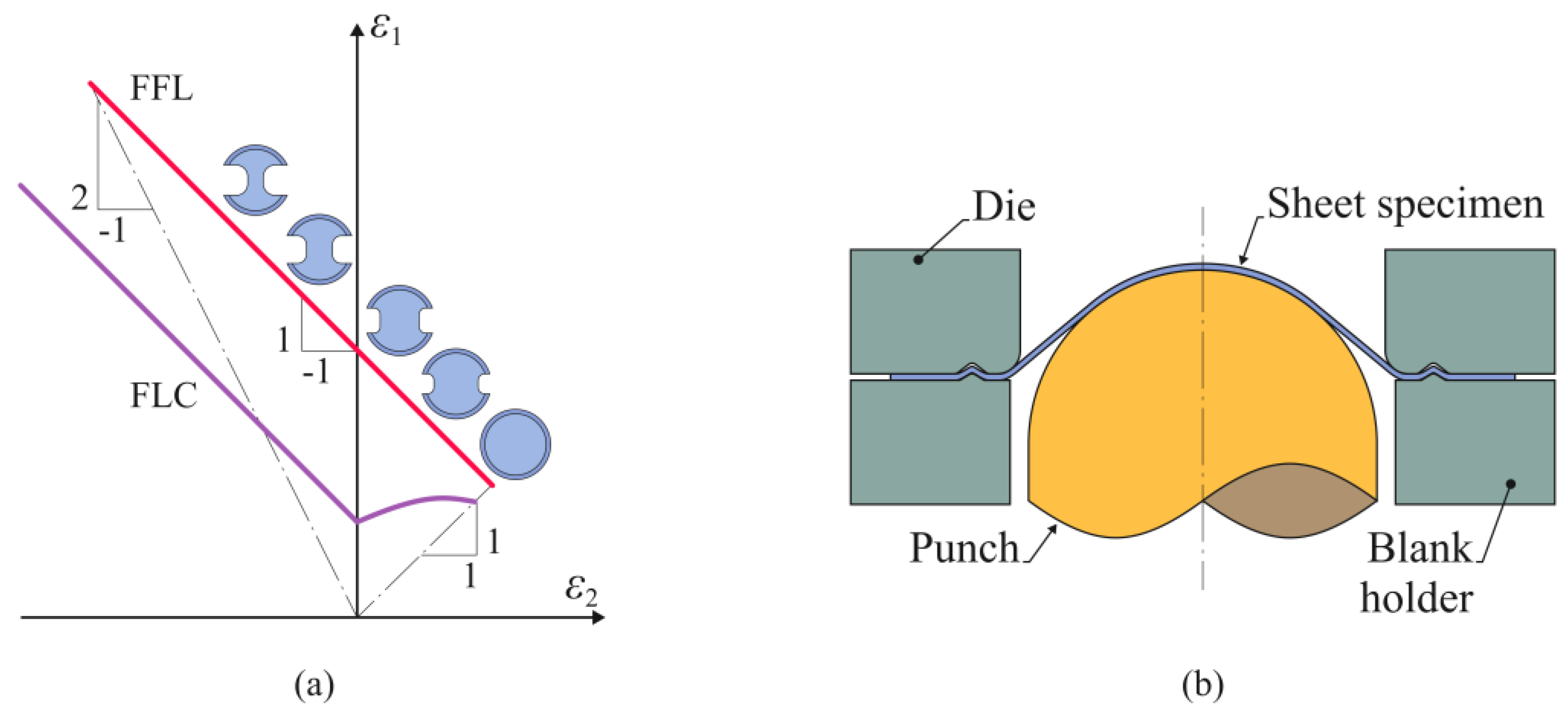
2.2. Dieless Nakajima Test

The novel dieless Nakajima test represents a breakthrough in assessing the formability of WAAM-deposited materials. It evaluates the material directly from the as-built parts without extracting sheet blanks, using the tool setup of conventional Nakajima sheet formability tests, which typically involve a punch, a die, and a blank holder. The dieless Nakajima test requires the web plates of the deposited walls to be machined to create a testing region of uniform thickness and excellent surface quality that mimics the die opening of conventional Nakajima tests (Figure 3c).
In this work, the diameter of the testing region was 73.5 mm, which is more compact, with a 0.7 size ratio compared to that recommended in the ISO 12004-2 [22] standard. This adjustment was needed to ensure compatibility with the free working area available for testing and to reduce the punch forces applied to the deposited walls during the dieless Nakajima test. However, it is worth noting that other authors who used a smaller punch and die setup from the Marciniak test, also included in the ISO 12004-2 standard, have already successfully used compact formability setups with sizes smaller than those recommended in the standards [23].
The testing region, which was 1 mm thick, was prepared to replicate the circular and arc-shaped blanks commonly used to obtain equibiaxial and uniaxial strain loading conditions, respectively (Figure 3c). The arc-shaped geometry was obtained through waterjet cutting.
Other arc-shaped test geometries with different curvature radiuses could have been machined to obtain different strain loading paths, but the authors focused solely on the two geometries shown in Figure 3c for this proof-of-concept validation work.
The edges of the deposited walls were machined perpendicularly to the building direction. This procedure is crucial to obtain grooved shapes with good surface quality for subsequent fixing and performing the proposed dieless Nakajima tests using a multidirectional tool [24] (Figure 4a).
The circular test geometry shown in Figure 4a was preferentially used in in the presentation because it requires larger forces, making it critical for designing and validating the dieless Nakajima testing setup.
The multidirectional tool converts the vertical crosshead movement of an Instron SATEC 1200 hydraulic testing machine into the horizontal movement of a hemispherical punch with a 70 mm diameter. This is achieved using a cam slide unit with a working angle α = 30 ° that consists of a punch holder and a sliding wedge actuator attached to the upper bolster (refer to the right-hand scheme in Figure 4a). The friction coefficient between the wedge actuator and the punch holder was verified to be μ     0.26 [24]. Regarding contact with the specimen, a 0.5 mm Teflon sheet was added between the punch and the testing region of the deposited walls to minimize friction.
Under these circumstances, the kinematical compatibility along the vertical y and horizontal x directions of the cam slide unit provides the following relation:
v x = v y tan α
This means that by moving the crosshead with a constant downward velocity ( v y = 5 mm/s), the testing occurs with a hemispherical punch velocity ( v x 2.9 mm/s).
As can be observed in Figure 4b, the side of the region of interest opposite to the punch was painted white and was then covered with a stochastic black dot pattern. This was to ensure reliable collection of the evolution of in-plane strains over time ε 1 ( t ) and ε 2 ( t ) , using a commercial digital image correlation (DIC) system from Dantec Dynamics (model Q-400 3D, Skovlunde, Denmark). This system featured two 6-megapixel resolution cameras equipped with 50.2 mm focal length lenses and f/8 aperture (Figure 4b). The region of interest was illuminated by a spotlight during testing, and images were captured by the cameras at a shutter frequency of 10 Hz.
Using the software previously developed by the authors [20], evolutions of in-plane strains over time, ε 1 ( t ) and ε 2 ( t ) , were automatically combined into strain loading paths ε 1 = f ε 2 in principal strain space by removing the time dependency.

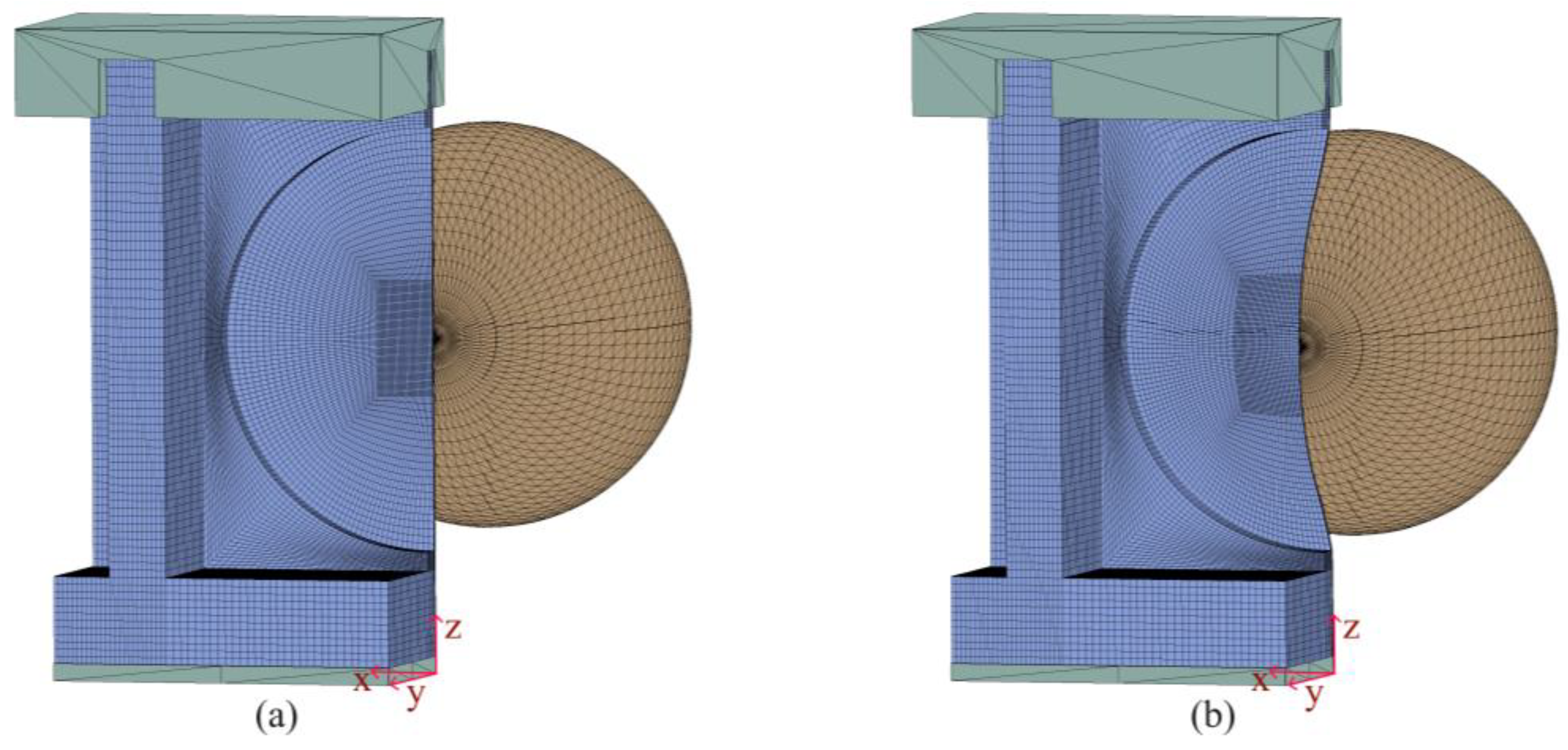
2.3. Numerical Simulation

The geometry of the deposited walls was defined using finite element modeling of the new proposed dieless Nakajima test. The work utilized the in-house computer program i-form (version 10.3), built upon the finite element flow formulation. The theoretical and numerical background of this program is detailed elsewhere [25].
The models treated the deposited walls as deformable objects, and the material was assumed to be isotropic, following the Levy–Mises constitutive equation. The flow stress used was retrieved from a previous study by the authors [21].
σ = 1200 ε 0.35   ( MPa )
Considering the symmetry plane y z , the deposited walls were discretized with approximately 50,000 three-dimensional hexahedral elements, with a more refined discretization at the center of the region of interest, where the hemispherical punch first contacts the deposited material.
The hemispherical punch and the grips holding the upper end of the deposited walls were assumed to be rigid objects and discretized using spatial triangular elements with friction. The Prandtl law of constant friction was utilized, with the friction factor in contact with the punch and the lower bolster of the multidirectional tool, equal to 0.1 and 1.0, respectively. The first value accounted for the Teflon sheet placed on the region of interest [26], whereas the second value allowed the model to accurately replicate the fixation of the odd-sized deposited walls to the lower bolster, similar to how bolts are used in actual testing. Figure 5 presents a view of the finite element model for the circular test geometry.
The accumulation of damage D Mc was modeled using the McClintock [27] fracture criterion (3), as it accounts for crack opening by tension (mode I of fracture mechanics), which is known to be the likely mode of failure in this type of specimen, as follows:
D Mc = 0 ε ¯ η d ε ¯
where ε ¯ is the effective strain and η = σ m / σ ¯ is the stress triaxiality.

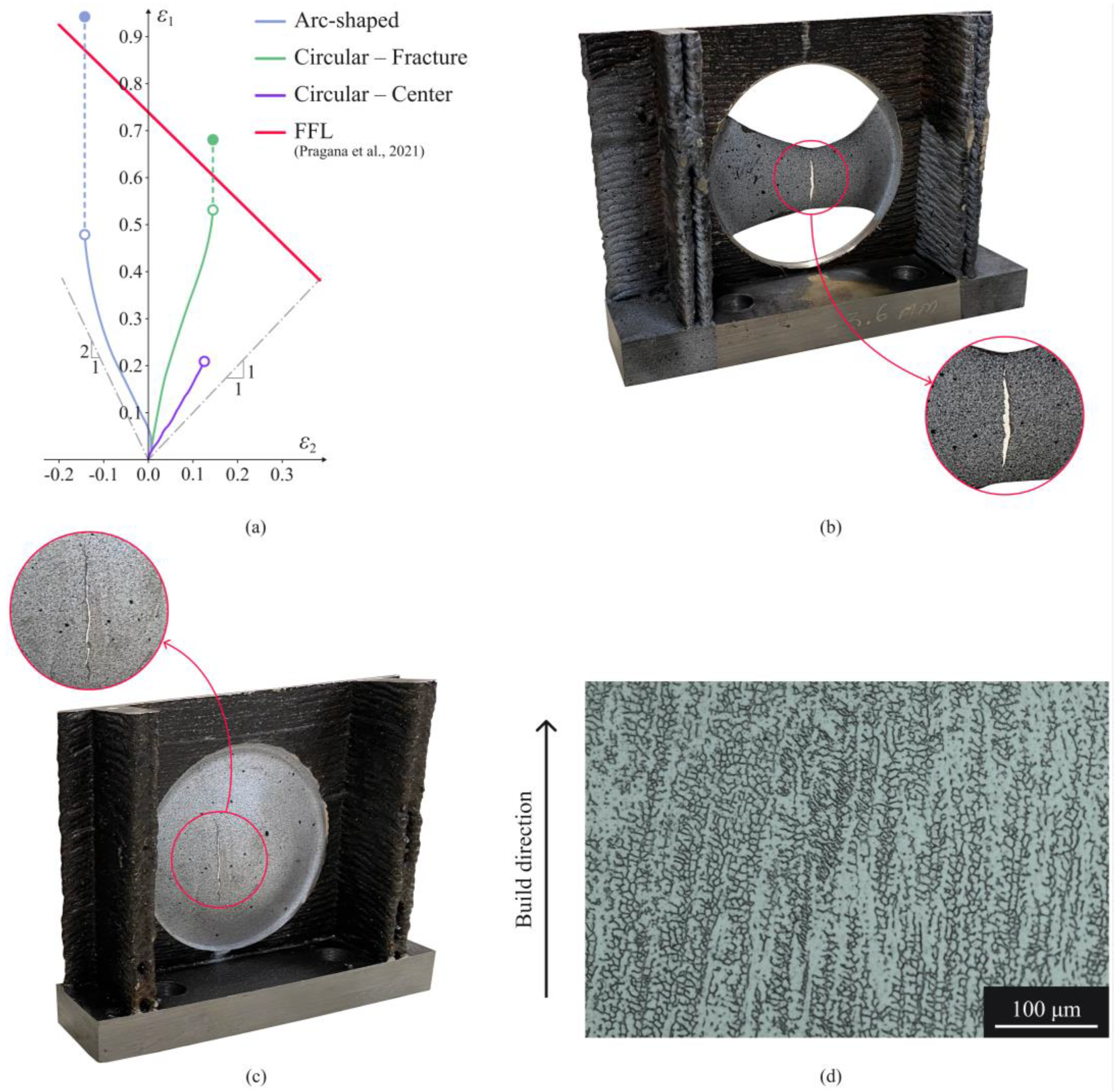
3. Results and Discussion

3.1. Test Design

The finite element predicted the distribution of effective strain for the circular test geometry, as depicted in Figure 6a. This prediction provides reassurance that the deposited walls outside the area of interest possess sufficient strength to maintain their original structural integrity. Their function is akin to the die and blank holder of the sheet, which is mimicked by the thinner machined area of interest undergoing plastic deformation due to contact with the hemispherical punch. The forces applied in the punch and grips are also kept at a safe level below 100 kN, ensuring that the multidirectional tool can host the dieless Nakajima tests safely.
The accumulation of damage, as predicted by the finite element method and disclosed in Figure 6b, is in close agreement with what is typically observed on circular blanks during conventional Nakajima tests using toolsets with a punch, a die, and a blank holder. This agreement further underscores the validity of the new procedure and its reliability in terms of results.
The above finite element results represent a promising first step in the proof-of-concept validation. In fact, the novel dieless Nakajima test shows potential to directly characterize formability from the deposited material, thereby eliminating the need to extract sheet blanks or use special-purpose tool setups.
Another crucial step in test design is verifying the finite element predicted strain loading path ( ε 1 = f ε 2 ) for the circular test geometry at the center of the area of interest, where it is in contact with the punch pole. This task is crucial to confirm whether this strain loading path undergoes equibiaxial tension with a slope of ‘1′. The results shown in Figure 7 confirm that the dieless Nakajima test can effectively replicate the states of strain found in the conventional Nakajima test performed with a circular blank in a tool setup.

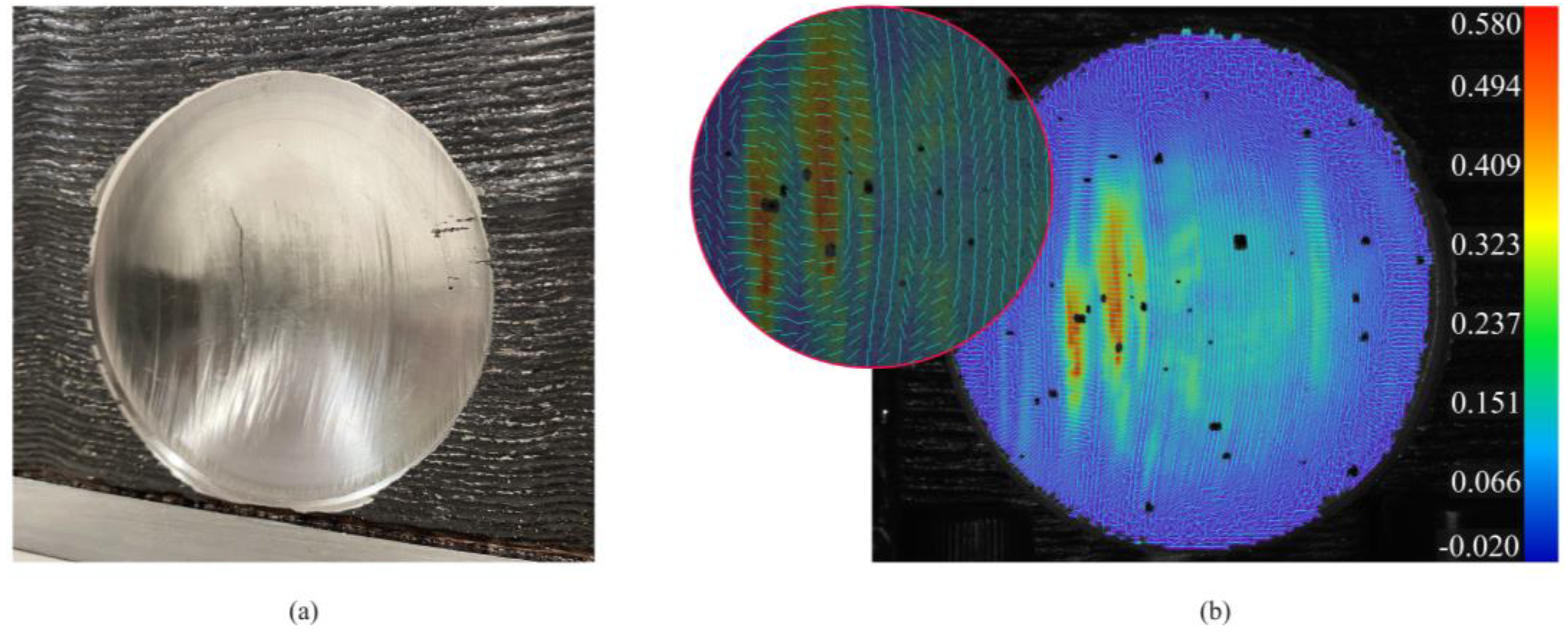
3.2. Experimental Test

Figure 8a shows the experimental strain loading paths ( ε 1 = f ε 2 ) obtained from DIC using the methodology and software described in Section 2.2 for the circular and arc-shaped test geometries shown in Figure 3c.
In both cases, the open markers represent the final DIC measurements in the area where the crack was triggered, whereas the solid markers denote the in-plane strains at the fracture. The latter were obtained from thickness measurements along the crack to determine the thickness strains given by ε 3 = l n t f / t o , where t o is the initial thickness and t f is the thickness at fracture, assuming no change in the minor strain( ε 2 = 0 ) after the last DIC measurement.
The results obtained for the arc-shaped test geometry (Figure 8b) demonstrate the dieless Nakajima testing setup’s capability of replicating uniaxial strain loading paths in principal strain space.
In the case of circular test geometry, two locations were selected, corresponding to the center and the area where the crack was triggered. The strain loading paths corresponding to these two locations differ and confirm that the location of the crack shifted slightly away from the center (Figure 8c). This is in close agreement with the fracture forming limit (FFL) for this material previously determined by the authors [21] (refer to the red line in Figure 8a).
The crack shift in the circular test geometry is attributed to the combined effects of lubrication and anisotropy. The lubrication provided by the Teflon sheet placed on the area of interest effectively reduced friction and gave rise to a more uniform distribution of strain than in the case of high friction, allowing cracks to initiate in regions other than the center. Anisotropy, on the other hand, is caused by the dendritic-based columnar grain microstructure of the deposited walls (Figure 8d), resulting from the heating and cooling cycles of WAAM. It contributes to the crack moving away from the center and explains the direction of crack propagation along the build direction, which aligns with dendrite growth.
Figure 9 provides further insight into the direction of crack propagation for the circular test geometry, showing a photograph of a specimen and the corresponding DIC results. As seen in Figure 9a, the cracks run vertically, aligning with the vertical stretch marks that follow the build direction. This alignment is not coincidental and significantly correlates with the distribution of the major in-plane principal strain ( ε 1 ) obtained by DIC. The visual evidence of the cracks aligning with the peak values of ε 1 , and the stretch marks being consistent with the vertical bands resulting from sharp changes in the vector orientations of ε 1 (refer to the light-blue vectors in Figure 9b), strongly indicates this relationship.
From a metallurgical perspective, this behavior is attributed to the above-mentioned dendritic-based columnar grain microstructure of the deposited walls, which aligns with the build direction and typically consists of austenite. In stainless steels, ferrite precipitates preferentially in the interdendritic regions [28]. As ferrite generally has lower fracture toughness than austenite [29] due to its BCC crystal structure, it is plausible that cracks initiate in the precipitated ferrite in the interdendritic regions. These precipitates then act as pathways for crack propagation, allowing cracks to follow paths of less resistance and potentially leading to more extensive damage.

4. Conclusions

The novel dieless Nakajima test enables direct characterization of the formability of deposited materials without extracting sheet blanks, using the special-purpose tool setup of conventional sheet formability tests. The regions of interest undergoing plastic deformation during testing must be machined to obtain the required sizes, ensuring uniform thickness and good surface quality.
The results obtained with circular and arc-shaped geometries confirm the validity of the proposed design, which utilizes the surrounding material of the region of interest as the die and blank holder, ensuring strain loading paths similar to those obtained in conventional Nakajima sheet formability tests.
The shift of cracks away from the center of the region of interest, opposite the hemispherical punch pole, in the case of circular geometry is attributed to good lubrication and anisotropy. The latter, typical of wire arc additive manufacturing, is due to the dendritic-based columnar grain microstructure of the deposited walls. The direction of crack propagation along the build direction, which aligns with dendrite growth, is compatible with the distribution of the major in-plane strain, namely with the vertical bands resulting from sharp changes in the vector orientations of these strains, as obtained from digital image correlation.

Author Contributions

Conceptualization, R.F.V.S., J.P.M.P., I.M.F.B., and C.M.A.S.; methodology, R.F.V.S., P.M.S.R., J.P.M.P., I.M.F.B., C.M.A.S., L.G.R., and P.A.F.M.; software, R.F.V.S. and P.A.F.M.; validation, R.F.V.S. and I.M.F.B.; formal analysis, R.F.V.S.; investigation, R.F.V.S., P.M.S.R., J.P.M.P., I.M.F.B., C.M.A.S., L.G.R., and P.A.F.M.; resources, L.G.R. and P.A.F.M.; data curation, R.F.V.S.; writing—original draft preparation, R.F.V.S. and P.A.F.M.; writing—review and editing, R.F.V.S., P.M.S.R., J.P.M.P., I.M.F.B., C.M.A.S., L.G.R., and P.A.F.M.; visualization, R.F.V.S.; supervision, J.P.M.P., I.M.F.B., C.M.A.S., L.G.R., and P.A.F.M.; project administration, C.M.A.S. and P.A.F.M.; funding acquisition, C.M.A.S. and P.A.F.M. All authors have read and agreed to the published version of the manuscript.

Funding

This research was funded by Fundação para a Ciência e a Tecnologia of Portugal and IDMEC under LAETA-UIDB/50022/2020 and PTDC/EME-EME/0949/2020. Rui F.V. Sampaio received funding from Fundação para a Ciência e Tecnologia of Portugal, grant number 2022.12351.BD.

Data Availability Statement

All data supporting the reported results are available in this paper.

Acknowledgments

The authors would like to acknowledge the support provided by Fundação para a Ciência e a Tecnologia of Portugal (FCT) and IDMEC through financial support from the project LAETA Base Funding (DOI: 10.54499/UIDB/50022/2020) and PTDC/EMEEME/0949/2020. Rui F.V. Sampaio would also like to acknowledge support received under PhD Studentship 2022.12351.BD.

Conflicts of Interest

The authors declare no conflicts of interest.

References

  1. Pragana, J.P.M.; Sampaio, R.F.V.; Bragança, I.M.F.; Silva, C.M.A.; Martins, P.A.F. Hybrid Metal Additive Manufacturing: A State–of–the-Art Review. Adv. Ind. Manuf. Eng. 2021, 2, 100032. [Google Scholar] [CrossRef]
  2. Bambach, M.; Sviridov, A.; Weisheit, A.; Schleifenbaum, J.H. Case Studies on Local Reinforcement of Sheet Metal Components by Laser Additive Manufacturing. Metals 2017, 7, 113. [Google Scholar] [CrossRef]
  3. Merklein, M.; Junker, D.; Schaub, A.; Neubauer, F. Hybrid Additive Manufacturing Technologies—An Analysis Regarding Potentials and Applications. Phys. Procedia 2016, 83, 549–559. [Google Scholar] [CrossRef]
  4. Ambrogio, G.; Gagliardi, F.; Muzzupappa, M.; Filice, L. Additive-incremental forming hybrid manufacturing technique to improve customised part performance. J. Manuf. Process. 2019, 37, 386–391. [Google Scholar] [CrossRef]
  5. Meiners, F.; Ihne, J.; Jürgens, P.; Hemes, S.; Mathes, M.; Sizova, I.; Bambach, M.; Hama-Saleh, R.; Weisheit, A. New Hybrid Manufacturing Routes Combining Forging and Additive Manufacturing to Efficiently Produce High Performance Components from Ti-6Al-4V. Procedia Manuf. 2020, 47, 261–267. [Google Scholar] [CrossRef]
  6. Merklein, M.; Schulte, R.; Papke, T. An Innovative Process Combination of Additive Manufacturing and Sheet Bulk Metal Forming for Manufacturing a Functional Hybrid Part. J. Mater. Process. Technol. 2021, 291, 117032. [Google Scholar] [CrossRef]
  7. López, C.; Elías-Zúñiga, A.; Jiménez, I.; Martínez-Romero, O.; Siller, H.R.; Diabb, J.M. Experimental Determination of Residual Stresses Generated by Single Point Incremental Forming of AlSi10Mg Sheets Produced Using SLM Additive Manufacturing Process. Materials 2018, 11, 2542. [Google Scholar] [CrossRef]
  8. Hafenecker, J.; Bartels, D.; Kuball, C.-M.; Kreß, M.; Rothfelder, R.; Schmidt, M.; Merklein, M. Hybrid Process Chains Combining Metal Additive Manufacturing and Forming – A Review. CIRP J. Manuf. Sci. Technol. 2023, 46, 98–115. [Google Scholar] [CrossRef]
  9. Cunningham, C.R.; Flynn, J.M.; Shokrani, A.; Dhokia, V.; Newman, S.T. Invited review article: Strategies and processes for high quality wire arc additive manufacturing. Addit. Manuf. 2018, 22, 672–686. [Google Scholar] [CrossRef]
  10. Sampaio, R.F.V.; Pragana, J.P.M.; Bragança, I.M.F.; Silva, C.M.A.; Nielsen, C.V.; Martins, P.A.F. Modelling of Wire-Arc Additive Manufacturing—A Review. Adv. Ind. Manuf. Eng. 2023, 6, 100121. [Google Scholar] [CrossRef]
  11. Bi, X.; Li, R.; Hu, Z.; Gu, J.; Jiao, C. Microstructure and Texture of 2205 Duplex Stainless Steel Additive Parts Fabricated by the Cold Metal Transfer (CMT) Wire and Arc Additive Manufacturing (WAAM). Metals 2022, 12, 1655. [Google Scholar] [CrossRef]
  12. Zhai, W.; Guo, Y.; Aishwarya; Canturri, C.; Shandro, R.; Zhou, W. Wire arc additive manufacturing of ER70S-6/S355 bimetal component. Mater. Sci. Eng. A 2024, 900, 146498. [Google Scholar] [CrossRef]
  13. Shah, A.; Aliyev, R.; Zeidler, H.; Krinke, S. A Review of the Recent Developments and Challenges in Wire Arc Additive Manufacturing (WAAM) Process. J. Manuf. Mater. Process. 2023, 7, 97. [Google Scholar] [CrossRef]
  14. Hönnige, J.R.; Colegrove, P.A.; Ahmad, B.; Fitzpatrick, M.E.; Ganguly, S.; Lee, T.L.; Williams, S.W. Residual Stress and Texture Control in Ti-6Al-4V Wire + Arc Additively Manufactured Intersections by Stress Relief and Rolling. Mater. Des. 2018, 150, 193–205. [Google Scholar] [CrossRef]
  15. Wu, B.; Pan, Z.; Ding, D.; Cuiuri, D.; Li, H.; Xu, J.; Norrish, J. A Review of the Wire Arc Additive Manufacturing of Metals: Properties, Defects and Quality Improvement. J. Manuf. Process. 2018, 35, 127–139. [Google Scholar] [CrossRef]
  16. Gornyakov, V.; Sun, Y.; Ding, J.; Williams, S. Modelling and Optimising Hybrid Process of Wire Arc Additive Manufacturing and High-Pressure Rolling. Mater. Des. 2022, 223, 111121. [Google Scholar] [CrossRef]
  17. Kaščák, L.; Varga, J.; Bidulská, J.; Bidulský, R. Simulation of 316L stainless steel produced the laser powder bed fusion process. Materials 2023, 16, 7653. [Google Scholar] [CrossRef] [PubMed]
  18. Nakajima, K.; Kikuma, T.; Hasuka, K. Study on the Formability of Steel Sheets. Yamata Tech. Rep. 1968, 264, 8517–8530. [Google Scholar]
  19. Isik, K.; Silva, M.B.; Tekkaya, A.E.; Martins, P.A.F. Formability limits by fracture in sheet metal forming. J. Mater. Process. Technol. 2014, 214, 1557–1565. [Google Scholar] [CrossRef]
  20. Sampaio, R.F.V.; Pragana, J.P.M.; Bragança, I.M.F.; Silva, C.M.A.; Martins, P.A.F. A Strain Acceleration Method to Identify the Onset of Diffuse Necking. Adv. Ind. Manuf. Eng. 2024, 9, 100148. [Google Scholar] [CrossRef]
  21. Pragana, J.P.; Bragança, I.M.; Reis, L.; Silva, C.M.; Martins, P.A. Formability of Wire-Arc Deposited AISI 316L Sheets for Hybrid Additive Manufacturing Applications. Proc. Inst. Mech. Eng. Part L J. Mater. Des. Appl. 2021, 235, 2839–2850. [Google Scholar] [CrossRef]
  22. ISO 12004-2; Metallic Materials-Sheet and Strip-Determination of Forming Limit Curves-Part 2. ISO: Geneva, Switzerland, 2008.
  23. Furushima, T.; Hirose, Y.; Tada, K.; Manabe, K. Development of Compact Marchiniak Testing Apparatus for In-situ Microscopic Observation of Surface Roughening. Procedia Eng. 2017, 207, 1946–1951. [Google Scholar] [CrossRef]
  24. Sapage, M.S.T.; Pragana, J.P.M.; Sampaio, R.F.V.; Bragança, I.M.F.; Silva, C.M.A.; Martins, P.A.F. Multi-planar injection lap riveting. J. Adv. Join. Process. 2024, 9, 100175. [Google Scholar] [CrossRef]
  25. Nielsen, C.V.; Martins, P.A.F. Metal Forming, 1st ed.; Elsevier: New York, NY, USA, 2021. [Google Scholar] [CrossRef]
  26. Wang, Y.; Zhang, C. The determination of friction coefficient in Nakazima test and its application in predicting FLCs with modified M-K model. IOP Conf. Ser. Mater. Sci. Eng. 2020, 967, 012056. [Google Scholar] [CrossRef]
  27. McClintock, F.A. A Criterion for Ductile Fracture by the Growth of Holes. J. Appl. Mech. 1968, 35, 363–371. [Google Scholar] [CrossRef]
  28. Elmer, J.W.; Allen, S.M.; Eagar, T.W. Microstructural development during solidification of stainless steel alloys. Metall. Trans. A 1989, 20, 2117–2131. [Google Scholar] [CrossRef]
  29. Laukkanen, A.; Uusikallio, S.; Lindroos, M.; Andersson, T.; Kömi, J.; Porter, D. Micromechanics driven design of ferritic–austenitic duplex stainless steel microstructures for improved cleavage fracture toughness. Eng. Fract. Mech. 2021, 253, 107878. [Google Scholar] [CrossRef]
Figure 1. Schematic representation of material deposition using wire arc additive manufacturing (WAAM).
Jmmp 08 00180 g001
Figure 2. (a) Schematic representation of a forming limit diagram obtained through Nakajima testing with (b) a drawing showing the cross-section of a sheet specimen.
Jmmp 08 00180 g002
Figure 3. (a) Schematic representation of the deposition strategy and photographs of a pi-shaped vertical wall (b) as-built and (c) after machining the upper end and the central region for two different Nakajima test geometries. Note: all the dimensions are in mm.
Jmmp 08 00180 g003
Figure 4. Schematic representation of (a) the dieless Nakajima testing setup in the multidirectional tool and (b) the digital image correlation system used to obtain in-plane strain vs. time evolutions. Note: both images make use of a circular test geometry.
Jmmp 08 00180 g004
Figure 5. Finite element model of the dieless Nakajima test performed with circular geometry showing the (a) initial and (b) deformed configuration of the deposited wall.
Jmmp 08 00180 g005
Figure 6. Finite-element-predicted distributions of (a) effective strain and (b) ductile damage according to the McClintock fracture criterion after 20 mm punch displacement for a circular test geometry.
Jmmp 08 00180 g006
Figure 7. Finite-element predicted strain loading path at the center of the area of interest for a dieless Nakajima test performed with circular geometry.
Jmmp 08 00180 g007
Figure 8. (a) Experimental strain loading paths with photographs of the dieless Nakajima setups for (b) the arc-shaped and (c) circular geometries after testing. (d) Photograph of the microstructure of a metallurgical sample extracted from the as-built deposited wall. Note: The FFL in (a) was retrieved from [21].
Jmmp 08 00180 g008
Figure 9. Dieless Nakajima test performed on circular geometry. (a) Photograph of a deposited wall after cracking, showing various stretch marks along the build direction. (b) Distribution of the major in-plane principal strain ε 1 , with detail showing the corresponding vector orientations.
Jmmp 08 00180 g009
Table 1. Chemical composition of the AISI 316L stainless steel feedstock (wt%).
ElementFeCrNiMoMnSiNC
weight%65.018.212.02.61.70.40.040.01
Table 2. Summary of the WAAM processing parameters utilized in the deposition of AISI 316L.
Current [A]Voltage [V]Wire Feed Speed [m/min]Travel Speed [m/min]Gas Flow Rate [l/min]Layer Height [mm]
10016.560.5101.8
Disclaimer/Publisher’s Note: The statements, opinions and data contained in all publications are solely those of the individual author(s) and contributor(s) and not of MDPI and/or the editor(s). MDPI and/or the editor(s) disclaim responsibility for any injury to people or property resulting from any ideas, methods, instructions or products referred to in the content.

