Article

The Wettability and High-Temperature Properties of Porous BN/Si3N4 Ceramics Bonded with SiTi22 Filler

1
Heilongjiang Provincial Key Laboratory of CO2 Resource Utilization and Energy Catalytic Materials, School of Material Science and Chemical Engineering, Harbin University of Science and Technology, Harbin 150040, China
2
State Key Laboratory of Advanced Welding and Joining, Harbin Institute of Technology, Harbin 150001, China
*
Author to whom correspondence should be addressed.
J. Manuf. Mater. Process. 2024, 8(6), 279; https://doi.org/10.3390/jmmp8060279
Submission received: 9 September 2024 / Revised: 7 November 2024 / Accepted: 16 November 2024 / Published: 3 December 2024

Abstract

:
The wettability and high-temperature mechanical properties of porous BN/Si3N4 ceramics brazed with SiTi22 (wt. %) filler were studied. It is manifested that SiTi22 filler presents remarkable wetting and spreading capabilities on the porous BN/Si3N4 ceramic surface. An interfacial reaction layer is generated at the interface, and the thickness of the reaction layer initially grows and subsequently remains constant with the escalation of temperature. Carbon coating modification is beneficial to the wettability and high-temperature mechanical properties of porous BN/Si3N4 ceramics. The wetting driving force is mainly controlled by the interfacial reaction at the three-phase line of the wetting front. The mechanical properties of the carbon-coated joints are significantly enhanced in comparison with uncoated joints. The joint strength attains a maximum value of roughly 73 MPa in the shear test implemented at 800 °C. The strength of the joint is significantly enhanced mainly due to the TiN0.7C0.3 particles that consume energy by changing the crack propagation direction, and the SiC nanowires strengthen the connection by bridging.

1. Introduction

Porous BN/Si3N4 ceramics demonstrate the merits of exceptional chemical stability, high resistance to thermal shock, superior machinability, elevated strength, and outstanding oxidation resistance [1,2]. Furthermore, they exhibit a low and stable dielectric constant as well as dielectric loss within an extensive temperature range, which holds promising applications in aerospace radar components [3,4,5]. Nevertheless, the inherent brittleness of ceramic materials and the limitations of near-net shape-forming methods make it difficult to process large size and complex shape parts, which restricts their wide use in different fields [6]. Generally, ceramic materials can be assembled with themselves or gradient structures by means of bonding methods to fulfill specific structural or functional demands [7]. How to achieve reliable bonding of ceramic materials, especially the kind that meets the demands of high-temperature applications, has become a critical issue urgently needing resolution in the field of ceramic bonding.
There are few reports about porous BN/Si3N4 ceramic brazing connection, but in recent years, the research on porous Si3N4 ceramic brazing connection has increased gradually. Among them, research on Ag-Cu-Ti and its composite brazing filler for porous Si3N4 ceramics and metals has been relatively systematic [8,9,10,11]. The brazing temperature of these fillers typically ranges from 860 °C to 1100 °C, and the resultant joints possess favorable mechanical properties [10]. However, the service temperature of the joints is generally lower than 500 °C, which fails to satisfy the high-temperature application demands of porous Si3N4-based ceramic components [12,13,14]. Meanwhile, microcrystalline glasses of various systems have also been employed as brazing fillers for the connection of porous Si3N4 ceramics and dense Si3N4 ceramics [15,16]. But when the temperature exceeds 600 °C, the glass phase within the joint is prone to softening and crystallization, resulting in a rapid decline in mechanical properties.
To raise the service temperature of joints and boost the thermal compatibility between the filler and the matrix, researchers have added reinforcing phases with properties similar to those of ceramic base materials, like ceramic particles and whiskers, into conventional fillers to create composite fillers. For instance, introducing nanoscale Si3N4 particles into Ag-Cu28 (wt. %) filler for the brazing of TC4 alloy and Si3N4 ceramics [17,18], and introducing nanoscale TiN particles into Ag-Cu-Ti filler for the brazing of Si3N4 ceramics and Invar alloy [19], the joint strength has been significantly enhanced after the introduction of the reinforcing phase. This is primarily ascribed to the fact that the ceramic particles added to the filler can appropriately lower the thermal expansion coefficient of the composite filler, which is conducive to the mitigation of thermal stress in the joint. Moreover, dispersed ceramic particles can not only bring about a particle-strengthening effect but also prevent the growth of brittle compounds during brazing. To some extent, the approach of adding reinforcing phases to traditional active brazing filler metals is capable of reducing the residual stress within the joint and enhancing the joint strength. However, it will cause problems such as the segregation of the added phases in the joint, the difficulty in the added phases in wetting the matrix, and the difficulty in controlling the interface between the connection and the matrix, which will ultimately affect the improvement in joint performance [20,21]. Additionally, Co-based, Ni-based, and Pd-based high-temperature active brazing alloy systems are frequently employed to join Si3N4 ceramics in order to raise the joint service temperature [22,23]. Generally, when the brazing temperature exceeds 1100 °C, the active element in the brazing filler metal will react strongly with the matrix at the interface to form a stable compound, which will significantly affect the wettability between the filler and the matrix, and then affect the mechanical properties of the joint [24].
In order to improve the high-temperature application requirements of ceramic bonded components, authors previously used high-temperature silicon-based brazing alloys (SiTi22 (wt. %) and SiCo22.5 (at. %)) to bond porous BN/Si3N4 ceramics and designed a brazing method that involved in situ self-generation of SiC nanowires to strengthen the interface [25,26]. The interface reaction mechanisms of the porous BN/Si3N4 ceramics joints were studied in detail, but research on the wetting mechanisms and high-temperature properties of the joints has not yet been conducted. Therefore, based on previous studies, this paper focuses on the wetting and spreading mechanism as well as the high-temperature mechanical properties of porous BN/Si3N4 ceramics brazed with SiTi22 filler.

2. Experimental Materials and Methods
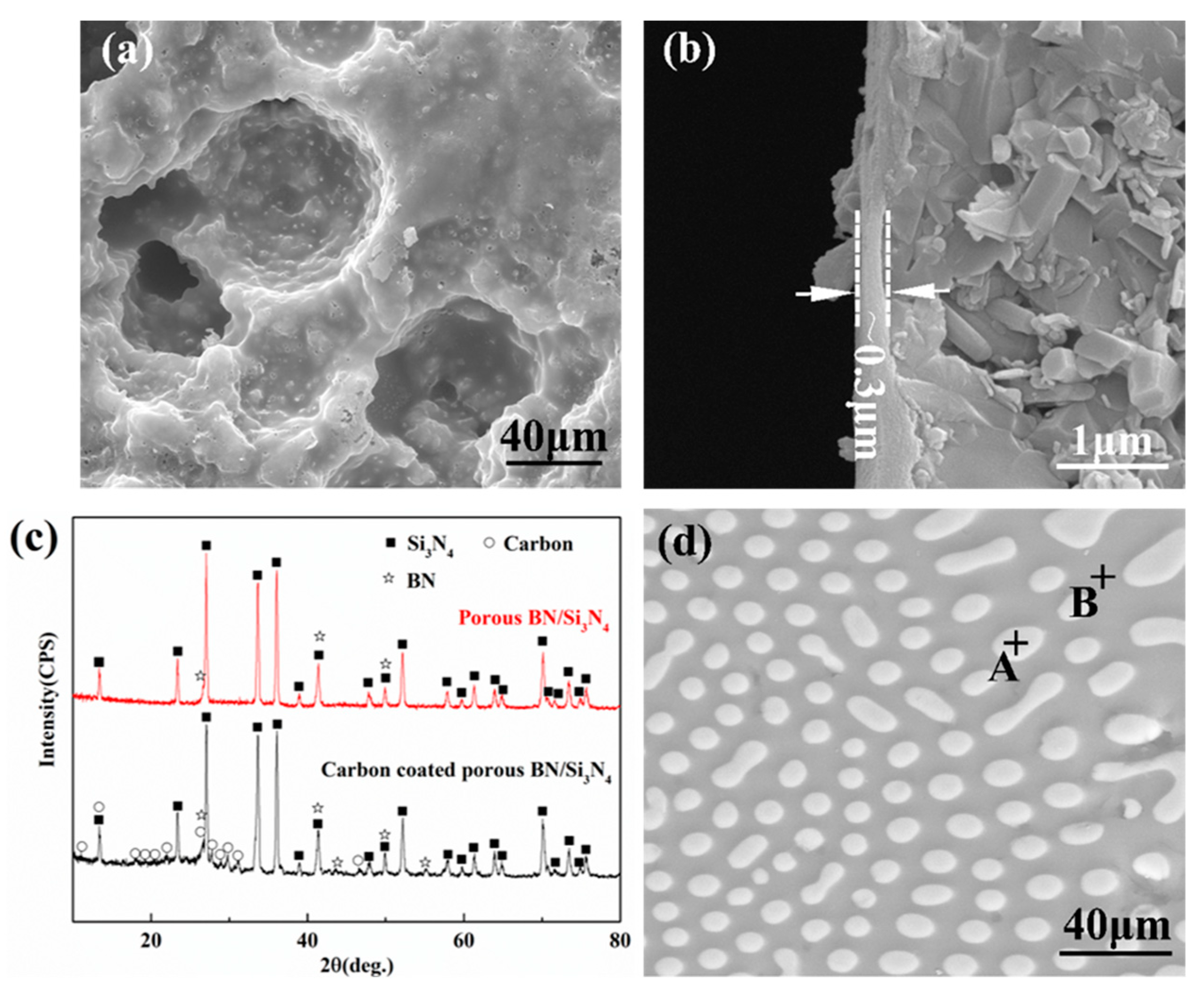
2.1. Materials

Porous BN/Si3N4 ceramics: The porous BN/Si3N4 ceramics employed in this paper were based on Si3N4 (possessing an average particle size of 0.5 μm, furnished by Shanghai Junyu Ceramic and Plastic Products Co., Ltd., Shanghai, China) and h-BN (boasting an average particle size of 0.5 μm, sourced from Beijing Chemical Reagent Company Co., Ltd., Beijing, China) powder as raw materials. Al2O3 (exhibiting an average particle size of 100 nm, analytically pure, with a purity exceeding 99.9%) and Y2O3 (displaying an average particle size of 50 nm, analytically pure, with a purity surpassing 99.9%) powder were used as sintering additives. In addition, 10 μm polymethyl methacrylate (PMMA) microspheres (provided by Beijing Antag Technology Development Co., Ltd., Beijing, China, and having a density of 1.19 g/cm3) were used as the pore-making agent. It was fabricated by cold isostatic pressing and sintering without pressure. The BN content was fixed at 10 vol. %.
Carbon-coated porous BN/Si3N4 ceramics: The thermosetting phenolic resin was dissolved in methanol to form an organic solution, and then the porous BN/Si3N4 ceramic sample was impregnated in the phenolic resin organic solution (the volume ratio of phenolic resin to methanol was 1:2) under a 0.9 × 10⁻¹ MPa vacuum for 15 min. It was cured at 60 °C for 1 h, then at 110 °C for 1 h, and, finally, at 160 °C for 2 h. The cured sample was pyrolyzed in a sintering furnace at 1100 °C under a vacuum of 1.5 × 10⁻² Pa for 15 min to obtain carbon-coated porous BN/Si3N4 ceramics. The microscopic morphology and phase composition of the porous BN/Si3N4 ceramic sample after carbon coating were analyzed, as depicted in Figure 1. It can be observed that the surface of the porous BN/Si3N4 ceramic modified by phenolic resin organic solution is covered with a layer of coating (Figure 1a,b). Based on the XRD results (Figure 1c), the characteristic peaks of silicon nitride and boron nitride are in accordance with the PDF cards of 33-1160 and 34-0421, respectively. The 2θ values at 13.3°, 19.1°, 27.8°, and 29.7° correspond, respectively, to the (002), (201), (211), and (114) lattice planes of carbon (PDF:50-1363, 1364). The 2θ values at 18.1°, 21.9°, and 30.9°correspond, respectively, to the (110), (202), and (214) lattice planes of carbon (PDF: 48-1449). And the 2θ at 26.6°, 43.5°, and 46.3° correspond, respectively, to the (003), (101), and (012) lattice planes of carbon (PDF: 26-1079). In addition, a broad and low-intensity overlapping peak can be discerned in the vicinity of 2θ = 26°, which might potentially be the (002) graphite peak [27,28].
SiTi22 filler: The filler employed in this paper was SiTi22 (wt. %), fabricated from titanium sponge (provided by Beijing Xingrongyuan Technology Co., Ltd., Beijing, China, with purity >99.7%) and monocrystalline silicon (from Lingshouxian Heling Mineral Products Processing Plant Co., Ltd., Shijiazhuang, China, with purity > 99.8%). To guarantee the homogeneity in the microstructure of the filler, the titanium sponge and monocrystalline silicon were respectively divided into three equal parts. Subsequently, arc melting was utilized to melt the three parts of the filler into three button ingots. Finally, the three button ingots were merged into one filler ingot. When the filler ingot was utilized as a connection, it was sliced into 800 μm pieces by a wire cutter and polished in sequence by 800#, 2000#, and 3000# diamond sandpaper. The ultimate thickness of the filler was approximately 600 μm. Figure 1d presents the SEM image of SiTi22 filler. It can be noticed that SiTi22 filler metal mainly consists of two phases. Combined with energy spectrum analysis (Table 1) and previous studies, it can be concluded that the main components in the filler metal are TiSi2 and Si [25].
Sample processing: The porous BN/Si3N4 ceramic after sintering was a Φ55 mm × 5 mm thick circular plate sample. The porous ceramic was cut into 5 mm × 5 mm × 5 mm (for microstructure analysis) and 10 mm × 10 mm × 5 mm (for wetting analysis and shear strength testing) specimens using an inner circular cutting machine. The specimens were successively polished with 800#, 2000#, and 3000# diamond sandpaper. Before connection, the brazing alloy was cut to the same size as the connection surface of the base material. Both the base material and the brazing alloy were separately immersed in acetone for ultrasonic cleaning for about 30 min. After drying, they were ready to be used.

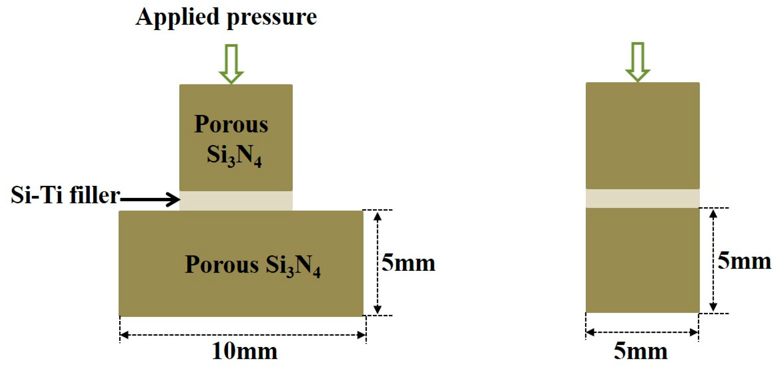
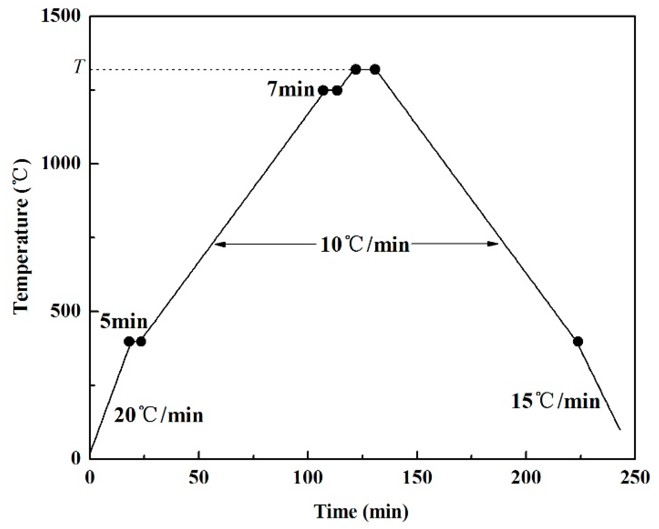
2.2. Experimental Method

This research project used a vacuum radiation heating multi-function furnace (CVI M60, Centorr Vacuum Industries, Nashua, NH, USA) for brazing bonding of porous BN/Si3N4 ceramics. The temperature control precision of the equipment was ±5 °C, and the vacuum level during the experiment was approximately 10−5 torr.
The connection of before and after carbon coating porous BN/Si3N4 ceramic samples was carried out by assembling them on graphite fixtures, as shown in Figure 2. After assembly, to ensure the stability of the samples during the connection process, two graphite plates were placed on the top of the samples, with a total mass of approximately 106 g and a generated pressure of 1.5 MPa. Once the welding specimen was assembled in a graphite fixture, the graphite fixture was positioned within the vacuum brazing furnace, and, subsequently, the furnace door was closed to evacuate the furnace chamber. The heating curve of the vacuum brazing furnace was set, as shown in Figure 3. When the vacuum degree reached 1.2 × 10⁻⁵ torr, the heating program was started: It was heated from room temperature to 400 °C at a rate of 20 °C/min and maintained for 5 min. Then, it was heated to 1250 °C at 10 °C/min and held for 7 min. Finally, it was heated to 1380 °C and maintained for 10 min. During the cooling process, the temperature was decreased to 400 °C at a rate of 10 °C/min and subsequently to 100 °C at a rate of 15 °C/min. Then, the heating program was terminated.
The mechanical properties of the joints were characterized by the shear strength. The porous BN/Si3N4 ceramic joints bonded together were installed in a fixture according to the schematic shown in Figure 4 and placed in an Instron 5569 electronic universal testing machine. The movement speed of the punch was 0.5 mm/s, and the load and displacement applied at the time of fracture were recorded.

3. Results and Discussion

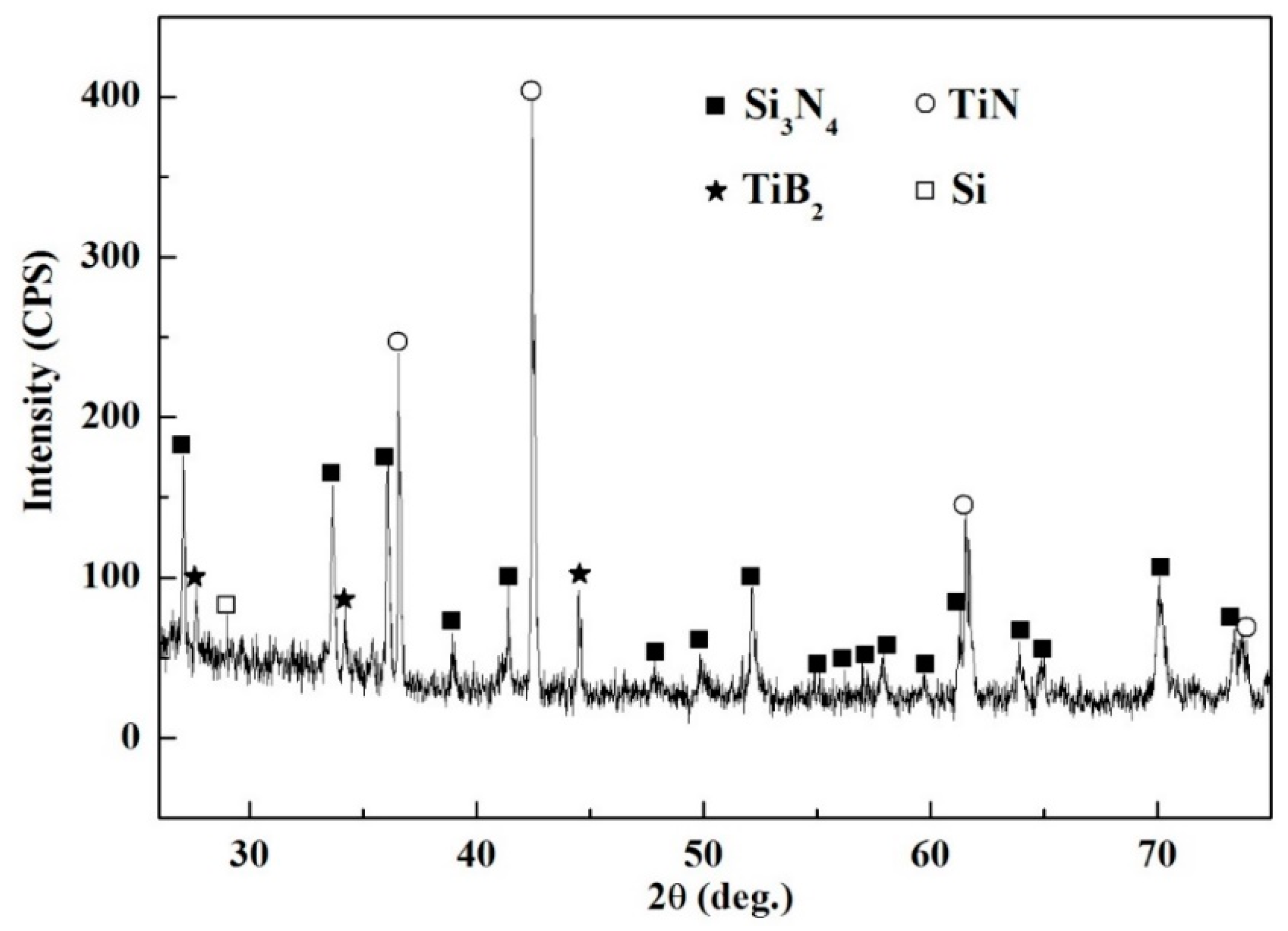
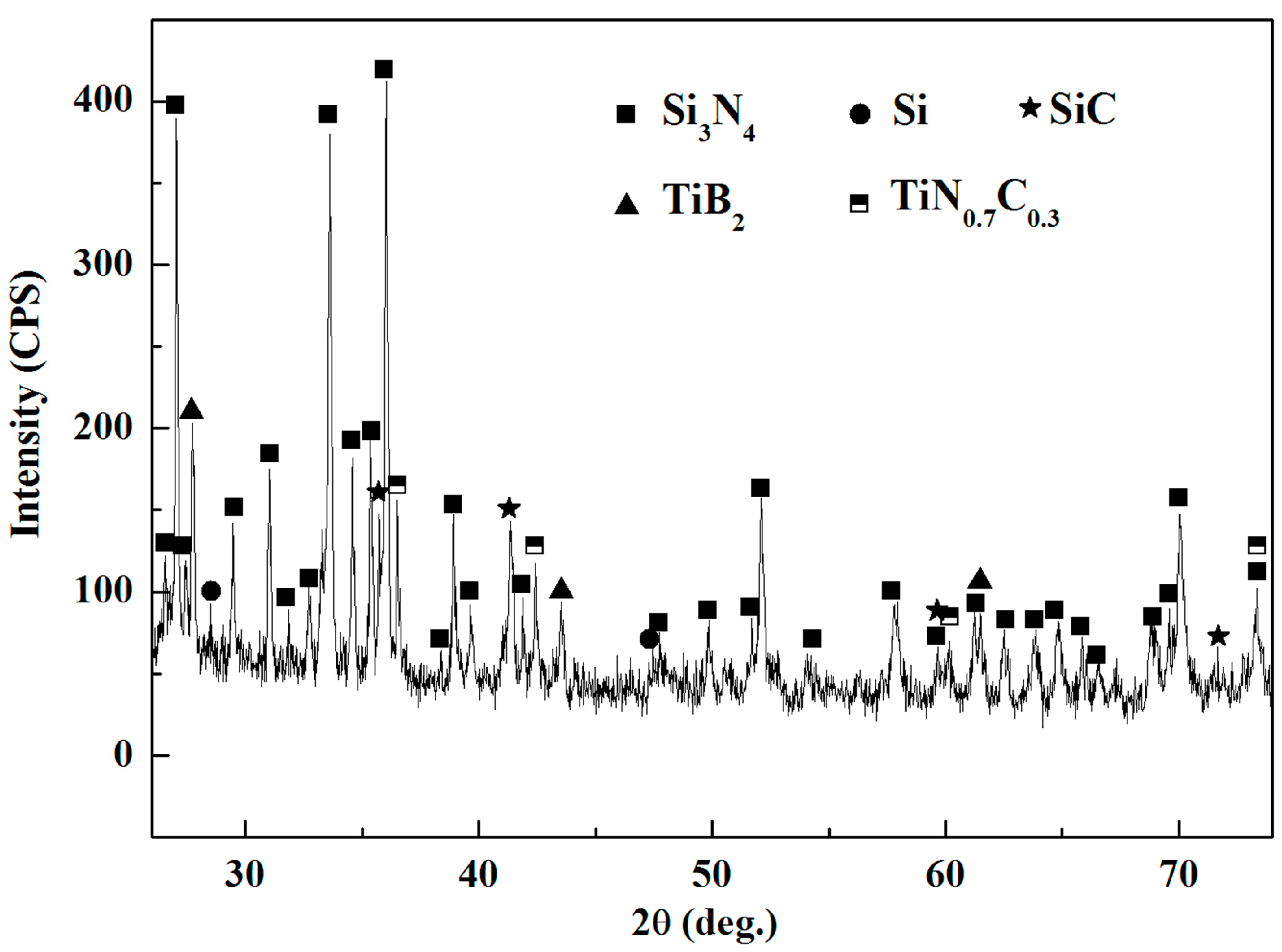
3.1. Wettability Analysis of the SiTi22/Porous BN/Si3N4 Ceramic System

The microstructure and composition of porous BN/Si3N4 ceramic joints connected by SiTi22 filler metal were characterized by SEM and energy spectrum analysis, as shown in Figure 5. Combined with the characterization results of Ref. [25] and EDS analysis (Table 2) of points A, B, C, and D, it can be determined that A and C in the weld are mainly TiN, B is TiSi2, and D is Si. The white phase at the interface may be the Y-Si-O ceramic intercrystalline phase.
The apparent contact angle and interface morphology of SiTi22 filler on porous BN/Si3N4 ceramics at different temperatures are depicted in Figure 6 and Figure 7, respectively. It can be observed from Figure 6 that the apparent contact angle exhibits a significant decrease with increasing temperature. When the temperature exceeds 1400 °C, the apparent contact angle becomes less than 5°, indicating excellent wettability of SiTi22 filler on the surface of porous BN/Si3N4 ceramics. As shown in Figure 7, a distinct interface reaction layer forms between the filler and base material. When the temperature increases from 1360 °C to 1380 °C, the thickness of this reaction layer increases from 15 μm to 24 μm. However, a further elevation in temperature does not significantly affect its thickness.
To determine the phase composition of the interface, XRD tests were carried out on the SiTi22 filler/porous BN/Si3N4 ceramics interface, and the results are presented in Figure 8. It is evident that TiN and TiB2 are formed at the interface, indicating that SiTi22 filler spreads on the porous BN/Si3N4 ceramic surface through reactive wetting. Thus, the primary driving force for wetting relies on the interface reaction at the three-phase line of the advancing front. The rise in temperature accelerates the rate of the interface reaction and decreases the viscosity of the filler. Consequently, under the same holding time conditions, higher temperatures lead to smaller apparent contact angles. Owing to a more intense interface reaction between Ti and the matrix, a continuous interfacial reaction layer forms promptly. This layer impedes further interaction between the filler and matrix. Therefore, when the thickness of the reaction layer reaches a certain extent, it terminates any subsequent reactions between the filler and matrix.

3.2. Influence of Surface Modification on the Wettability of the SiTi22/Porous BN/Si3N4 System

The prior analysis reveals that the intense interface reaction between the SiTi22 filler and the porous BN/Si3N4 ceramics gives rise to remarkable wettability and spreadability of the filler on the surface of the porous ceramic. However, when the temperature exceeds 1400 °C, the filler tends to flatten on the matrix surface, which may lead to its flow out of the weld during brazing and hinder joint connection. To solve this problem, porous BN/Si3N4 ceramics were modified by carbon coating, and the wettability and spreadability of the filler on the surface of the carbon-coated porous ceramics were examined.
Firstly, the interface between the SiTi22 filler and the carbon-coated porous BN/Si3N4 ceramic was characterized and analyzed, and the results are shown in Figure 9. Compared with the non-carbon-coated joints, the reaction products at the interface of the carbon-coated joints increased. Combined with the characterization results of Ref. [25] and EDS analysis (Table 3) of points A, B, C, and D, it can be determined that the interface products are mainly TiB2, TiNC, and SiC. At the same time, SiC nanowires are formed in the pores at the interface [25].

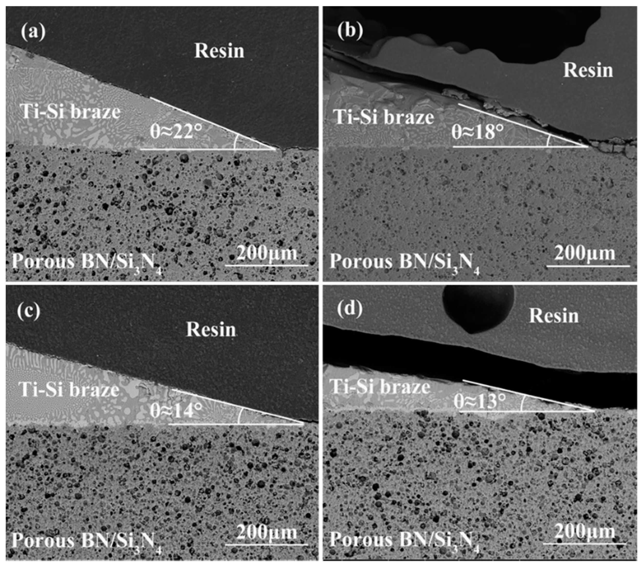
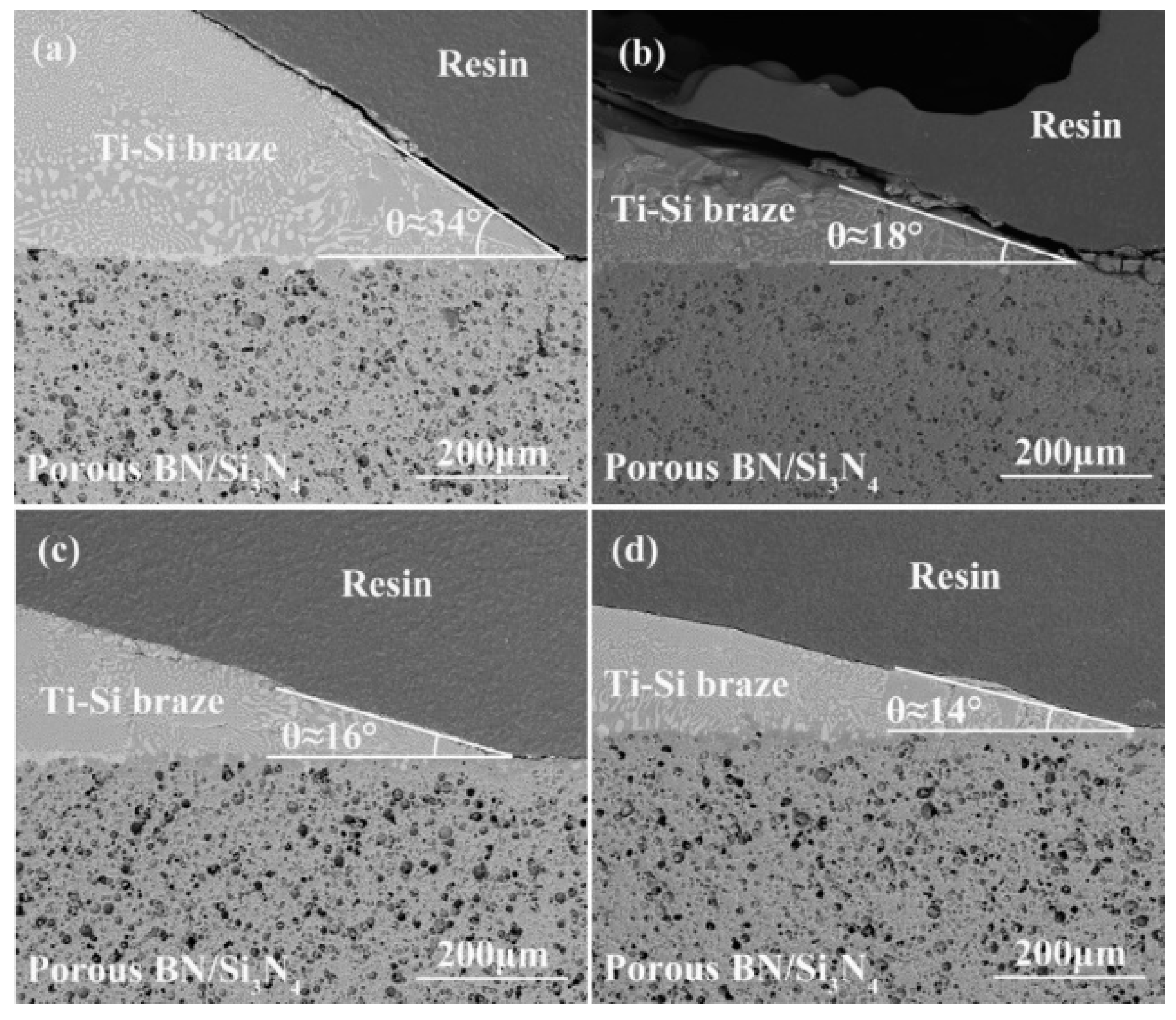
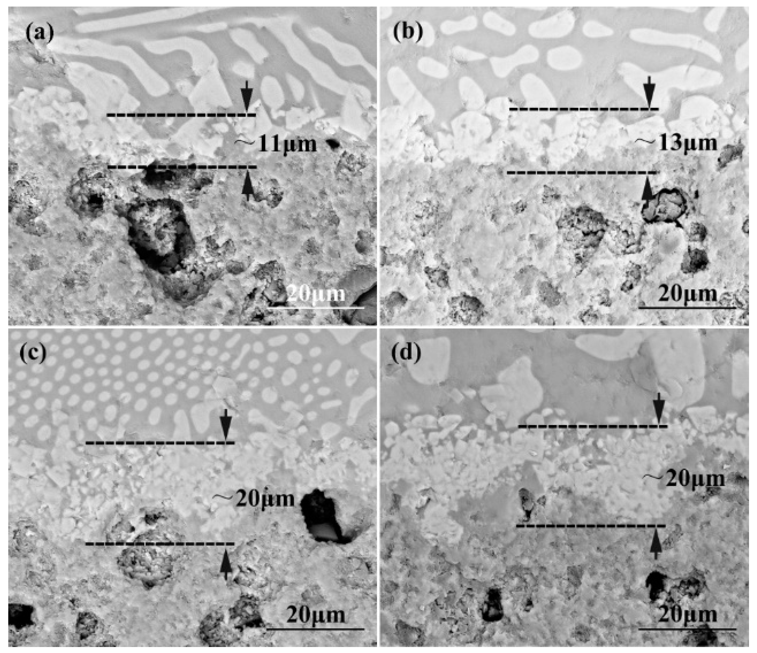
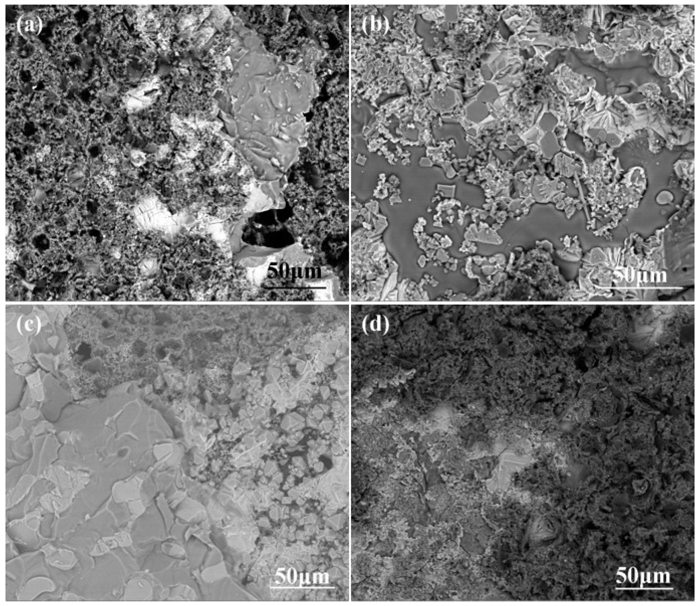
3.2.1. The Impact of Brazing Temperature on the Wettability of the System

The apparent contact angle and interface morphology of SiTi22 filler on the surface of carbon-coated porous BN/Si3N4 ceramics at different temperatures are shown in Figure 10 and Figure 11, respectively. Figure 10 reveals that the apparent contact angle of SiTi22 filler on the surface of carbon-coated porous BN/Si3N4 ceramics decreases gradually from 20° to 13° as the temperature rises. Furthermore, the contact angle remains relatively stable when the temperature exceeds 1400 °C. Figure 11 demonstrates that there is a significant increase in granular product formation on the surface of carbon-coated porous ceramics. Specifically, as the temperature increases from 1380 °C to 1400 °C, the thickness of the interface reaction layer increases from 11 μm to15 μm before stabilizing with further temperature increments. These changes can be attributed to both pre- and post-carbon coating reactive wetted spreading behavior exhibited by SiTi22 filler on surfaces of porous BN/Si3N4 ceramics.
In the uncoated carbon system, the filler directly interacts with the matrix, and the interface reaction is primarily controlled by the interaction between the active element Ti in the filler and BN and Si3N4. In the coated carbon system, due to the presence of a carbon film, the filler needs to penetrate through it and interact with the matrix, resulting in a relatively complex interface reaction. To determine the interface products in the coated carbon system, X-ray diffraction analysis was employed on SiTi22 filler/carbon-coated porous BN/Si3N4 ceramic interfaces (Figure 12). The results show that SiC and TiN0.7C0.3 appear in the carbon coating interface, while TiN disappears. This indicates that the Ti and Si within the filler react not only with BN and Si3N4 but also with the carbon layer during the interaction process, which leads to the formation of a TiN0.7C0.3 solid solution. These results indicate that it takes more time for SiTi22 fillers to form a new stable reaction interface on the carbon-coated porous BN/Si3N4 ceramic surface under similar conditions, thereby slowing down its diffusion rate and increasing its apparent contact angle.

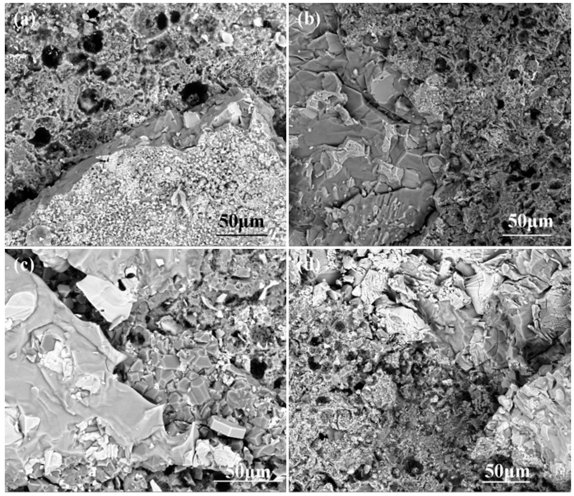
3.2.2. The Influence of Brazing Time on the Wettability of the System

The apparent contact angle and interface morphology of SiTi22 filler on the carbon-coated porous BN/Si3N4 ceramic surface at different holding times are illustrated in Figure 13 and Figure 14, respectively. It is evident that when the holding time increases from 5 min to 20 min, the apparent contact angle decreases from 34° to 14° (Figure 13), while the thickness of the interface reaction layer increases from 11 μm to 20 μm (Figure 14). This change can be attributed to the continuous interfacial reaction that occurs in the reactive wetting system as the holding time is prolonged. From a kinetic perspective, prior to reaching an equilibrium state, the filler will continue spreading freely on the matrix surface along with ongoing interface reactions, resulting in a gradual decrease in apparent contact angle over time. However, the accumulation of the product causes the formation of a continuous reaction layer at the interface. Once this reaction layer reaches a certain threshold thickness, the filler becomes hard to penetrate and has difficulty interacting with the substrate; thus, the interface reaction stops. Therefore, a maximum thickness of the reaction layer appears in a certain period of time.

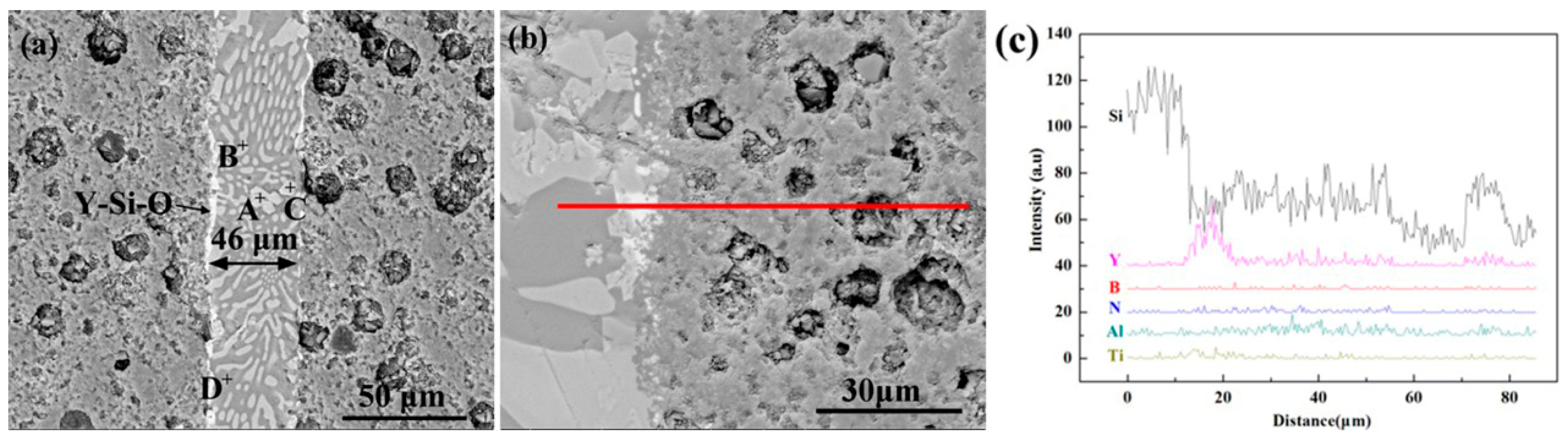
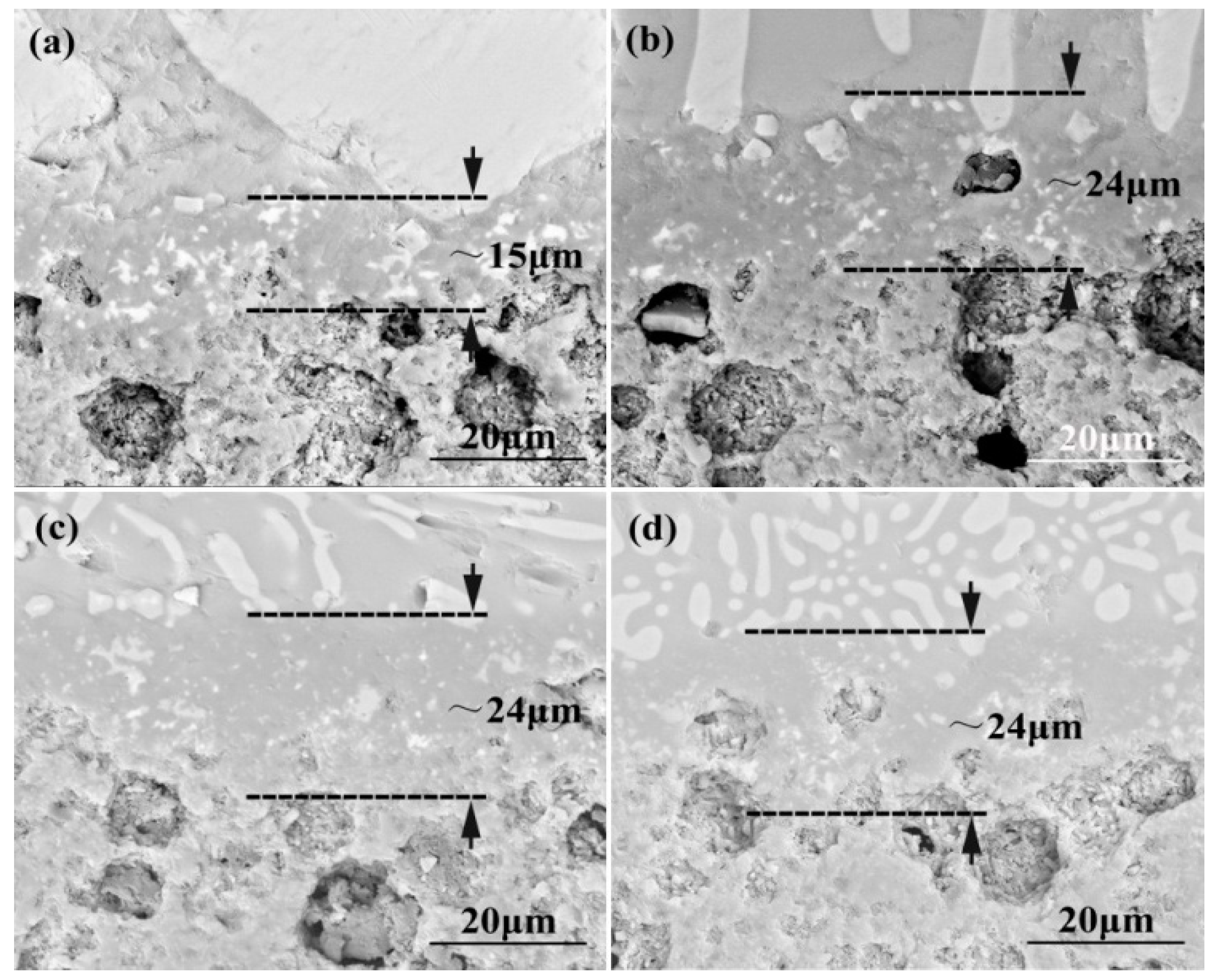
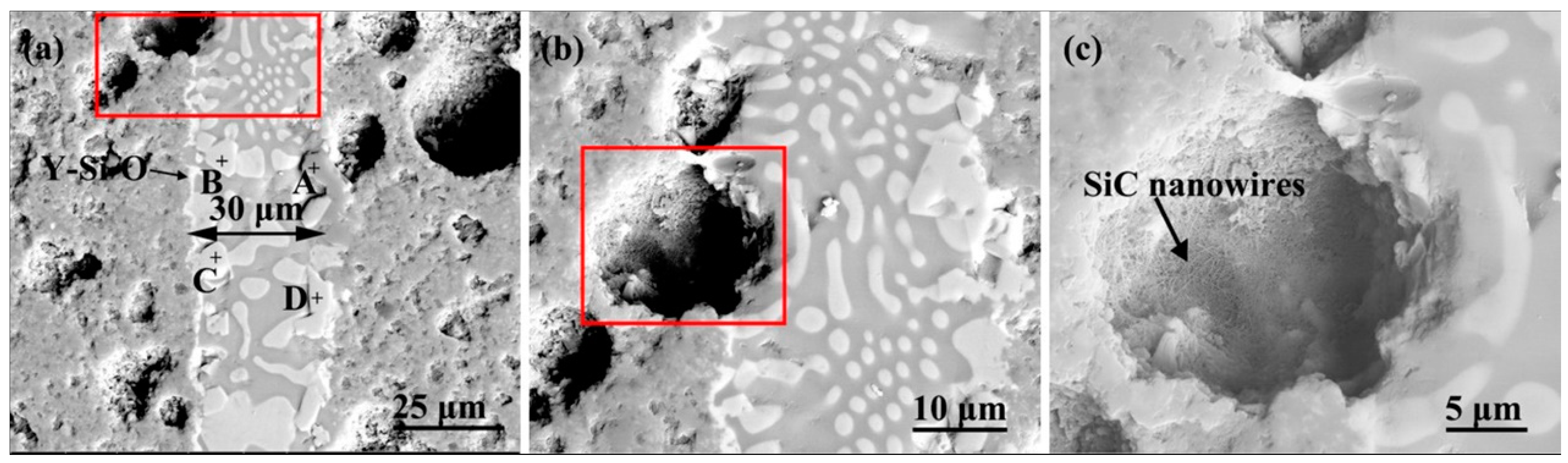
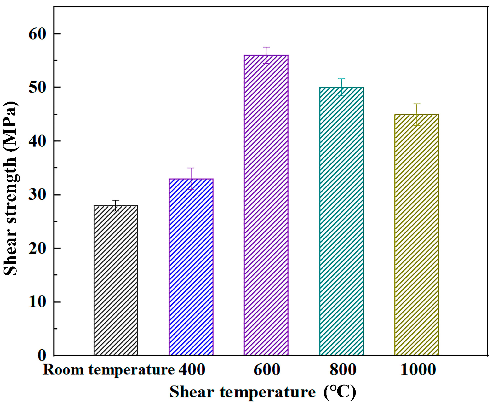
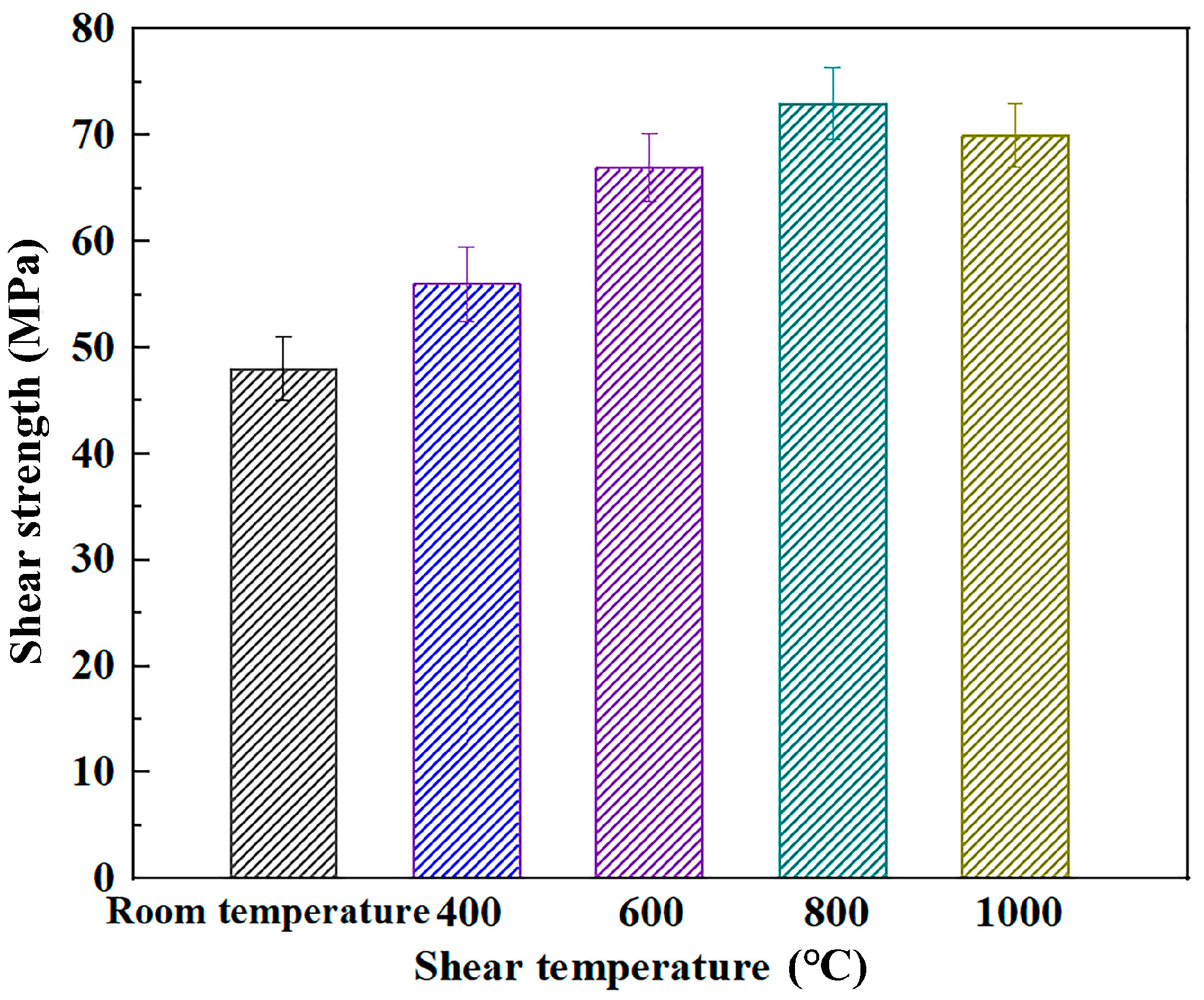
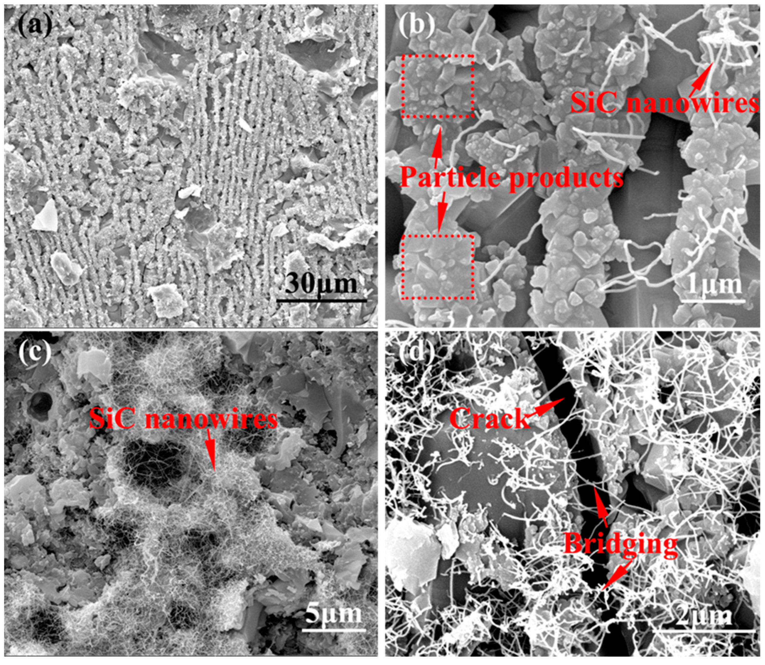
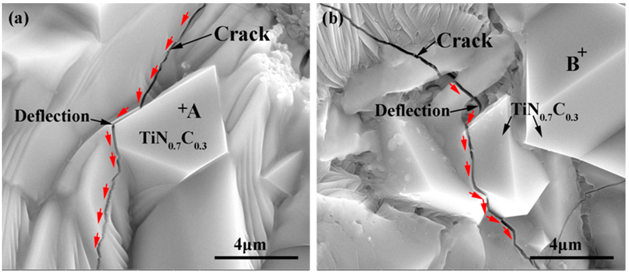
3.3. Mechanical Properties of Ceramic Joints at High Temperature

The high-temperature mechanical properties of porous BN/Si3N4 ceramic joints before and after carbon coating were investigated. As can be seen from Figure 15, the shear strength of the joint initially rises and subsequently declines as the test temperature ascends. The joint attains its maximum shear strength (approximately 56 MPa) at 600 °C, and the shear strength of the joints at high temperatures is superior to that at normal temperature. The corresponding fracture morphology of the joint during shearing is depicted in Figure 16. It can be observed that the majority of fractures take place at the joint interface, indicating that the joint interface is the weak area of the joint. Moreover, at different shearing temperatures, the ceramic base material and the microstructure of the interface products can be distinctly observed at the fracture locations. This is a typical brittle fracture, suggesting that the interface products have a significant influence on the shear strength of the joint [29]. Additionally, it can be observed that a portion of the filler is anchored on the ceramic at the fracture surface, and there exist diverse interface products. The distribution of TiN and TiB2 is uniform, with a minor amount of TiSi2 [25]. This indicates that the filler and the substrate have reacted sufficiently during the connection process. While the welding temperature and holding time remain unchanged, the mechanical properties of the joint are mainly influenced by the interface bonding force and the distribution of the microstructure. Generally, with the increase in temperature, the strength of the material decreases and the plasticity increases. At high temperatures, the diffusion rate of elements accelerates, which changes the distribution of the microstructure at the interface and can improve the mechanical properties of the joints within a certain range [30]. Nevertheless, when the temperature is excessively high, it will give rise to the aggregation and coarsening of the microstructure, leading to an uneven distribution of the interface microstructure and causing considerable interface thermal stress between the filler and the matrix. This constitutes the primary reason for the variation in the joint strength with the test temperature.
The high-temperature shear strength of the carbon-coated porous BN/Si3N4 ceramic joints was subjected to a comparative test, and the outcomes are depicted in Figure 17. Compared to the uncoated joint, the shear strength of the carbon-coated joints at room temperature witnessed a remarkable enhancement. With the rise in the test temperature, the strength of the joint gradually enhanced, and the maximal strength was approximately 73 MPa in the shear test at 800 °C. The strength experienced a minor decrement at 1000 °C, yet it still remained at about 68 MPa. This indicates that a carbon coating on the surface of porous BN/Si3N4 ceramics can effectively improve the mechanical properties and service temperature of the joint. The fracture morphology is shown in Figure 18. It can be seen that the fracture mainly occurs at the interface, indicating that the connection interface is still the weakest area in the joint. Based on previous research, the carbon-coated porous BN/Si3N4 ceramic joint contains TiN0.7C0.3, TiB2 particles, SiC nanowires, and SiC particles, which significantly enhance the joint’s mechanical properties [25].
In order to prove the effect of interface products on the mechanical properties of the joint, the typical interface morphology was analyzed, as shown in Figure 19 and Figure 20. It is evident from Figure 19a,b that a considerable number of granular products and nanowires are generated at the interface. As is observable from Figure 19c, the extracted nanowires remain at the fracture interface, suggesting that when the load is applied to the joint, the nanowires can absorb a portion of the energy through extraction [31]. Figure 19d depicts the crack formed at the interface of the fracture. It can be noted that SiC nanowires form bridges at the crack, indicating that the nanowires can also transfer a part of the energy through the bridge during the crack propagation.
Figure 20 reveals the crack at the interface of the fracture. Table 4 presents the outcomes of the energy spectrum analysis of granular products at the fracture, which can be regarded as TiN0.7C0.3. As observed in Figure 20a, the crack extends a considerable distance at the interface. Nevertheless, when it encounters the TiN0.7C0.3 grain, the expansion direction deflects. After the deflection, the crack propagates along the edge of the grain. The crack width gradually decreases after two deflections. As discerned from Figure 20b, when the crack encountered the first TiN0.7C0.3 grain during propagation, the propagation direction was significantly deflected, with an approximately 90° deflection angle. Subsequently, the crack continued along the edge of the grain and met another adjacent grain. The crack direction changed again. Since the two grains are close, the crack passes through the weak interface. This implies that the TiN0.7C0.3 grain has high strength, and its formation enhances the joint strength within a certain range. Due to the low BN content in the matrix, the number of TiB2 grains at the interface is small. Owing to the random fracture location, no obvious TiB2 grain blocking the crack is witnessed. However, TiB2 is the most stable compound of B and Ti with high hardness. Thus, a small amount of TiB2 grains at the interface may contribute to the improvement in the joint strength.
In conclusion, TiN0.7C0.3 particles consume energy by changing the direction of crack propagation. SiC nanowires strengthen the connection between the filler metal and the substrate by way of a bridge [29]. Under the action of load, the pulled nanowires are conducive to load transfer [32,33]. High temperature can accelerate the diffusion rate of elements at the interface, make the interface structure distribution more uniform, and stabilize the mechanical properties of the joint.

4. Conclusions

SiTi22 filler demonstrates outstanding wetting and diffusion capabilities on the porous BN/Si3N4 ceramic surface. The apparent contact angle decreases rapidly as the temperature rises. When the temperature exceeds 1400 °C, the filler almost spreads completely on the substrate surface. An interfacial reaction layer is formed at the interface, and the thickness of the reaction layer initially increases and then remains unchanged as the temperature increases. The carbon coating has a certain improvement effect on the wetting and spreading of SiTi22 filler. SiTi22 filler exhibits strong interfacial reactions at the porous BN/Si3N4 ceramic interface both before and after carbon coating. The wetting driving force is mainly controlled by the interfacial reaction at the three-phase line at the wetting front. High-temperature mechanical property investigations reveal that the mechanical properties of the carbon-coated joints are significantly enhanced in comparison with uncoated joints, and the mechanical properties of the carbon-coated joints at higher test temperatures are all superior to those at room temperature. The optimal mechanical properties were tested in the shear test at 800 °C, approximately amounting to 73 MPa. After carbon coating, the strength of the joint is significantly enhanced, mainly due to the TiN0.7C0.3 particles that consume energy by changing the crack propagation direction, and the SiC nanowires strengthen the connection by bridging.

Author Contributions

Methodology, P.L.; validation, H.C., P.L. and J.L.; formal analysis, X.W.; investigation, T.L.; resources, P.H.; data curation, H.C. and X.W.; writing—original draft preparation, Y.Z.; writing—review and editing, Y.Z.; supervision, L.D. and P.H.; project administration, D.L. and X.J.; funding acquisition, Y.Z. and P.L. All authors have read and agreed to the published version of the manuscript.

Funding

This research was supported by “National Natural Science Foundation of China (NSFC, 52105332; U21A20128, 52175302, U22A20185, 52305353)”. And The APC was funded by [NSFC, 52105332]. All individuals included in this section have consented to the acknowledgement.

Data Availability Statement

The research data will be permanently archived in the Swiss National Library (Helveticat) and the CLOCKSS database.

Conflicts of Interest

The authors declare no conflict of interest.

References

  1. Du, S.M.; Zhang, J.; Li, F.; Chen, Z.L.; Zhang, S.J.; Zhao, S.; Zhao, D.K.; Fan, B.B.; Chen, K.X.; Liu, G.H. Low temperature fabrication of highly dense α-Si3N4 ceramics. J. Am. Ceram. Soc. 2024, 107, 4494–4500. [Google Scholar] [CrossRef]
  2. Dong, X.J.; Wu, J.Q.; Yu, H.L.; Zhou, Q.; Wang, W.Q.; Zhang, X.Q.; Zhang, L.; Li, L.; He, R.J. Additive manufacturing of silicon nitride ceramics: A review of advances and perspectives. Int. J. Appl. Ceram. Technol. 2022, 19, 2929–2949. [Google Scholar] [CrossRef]
  3. Jiang, C.X.; Zhuang, Y.H.; Wang, J.J.; Liao, S.J.; Zhou, L.J.; Li, S.; Zhao, Y.X. Preparation, microstructure, and properties of GPS silicon nitride ceramics with β-Si3N4 seeds and nanophase additives. Int. J. Appl. Ceram. Technol. 2022, 19, 2533–2544. [Google Scholar]
  4. Yin, S.; Pan, L.M.; Fang, X.; Li, Y.F.; Li, Y.P.; Feng, Y.B.; Qiu, T.; Yang, J. Porous Si3N4 ceramics prepared by aqueous gelcasting using low-toxicity DMAA system: Regulatable microstructure and properties by monomer content. Ceram. Int. 2019, 45, 9994–10003. [Google Scholar] [CrossRef]
  5. Wang, C.; Wang, H.J.; Qiao, R.Q.; Zhang, C.H.; Chen, L.J. Fabrication and thermal shock resistance of β-Si3N4-based environmental barrier coating on porous Si3N4 ceramic. Ceram. Int. 2016, 42, 14222–14227. [Google Scholar] [CrossRef]
  6. Wang, S.J.; Jia, D.C.; Yang, Z.H.; Duan, X.M.; Tian, Z.; Zhou, Y. Effect of BN content on microstructures, mechanical and die-lectric properties of porous BN/Si3N4 composite ceramics prepared by gel casting. Ceram. Int. 2013, 39, 4231–4237. [Google Scholar] [CrossRef]
  7. Li, Z.W.; Xu, Z.W.; He, P.; Chen, S.; Ma, Z.W.; Ren, B.X.; Yan, J.C. Microstructure and enhanced joint performance of porous Si3N4 ceramics in ultrasonic soldering. Mat. Sci. Eng. A 2022, 840, 142984. [Google Scholar] [CrossRef]
  8. Zhao, Y.X.; Song, X.G.; Hu, S.P.; Zhang, J.Y.; Cao, J.; Fu, W.; Feng, J.C. Interfacial microstructure and mechanical properties of porous-Si3N4 ceramic and TiAl alloy joints vacuum brazed with AgCu filler. Ceram. Int. 2017, 43, 9738–9745. [Google Scholar] [CrossRef]
  9. Zhang, J.; Liu, J.Y.; Wang, T.P. Microstructure and brazing mechanism of porous Si3N4/Invar joint brazed with Ag-Cu-Ti/Cu/Ag-Cu multi-layered filler. J. Mater. Sci. Technol. 2018, 34, 713–719. [Google Scholar] [CrossRef]
  10. Liu, J.Y.; Zhang, J.; Liu, C.F.; Wang, T.P. Microstructure and mechanical properties of porous Si3N4/Invar joints brazed with Ag-Cu-Ti+Mo/Cu/Ag-Cu multi-layered composite filler. Ceram. Int. 2017, 43, 11668–11675. [Google Scholar] [CrossRef]
  11. Song, X.G.; Zhao, Y.X.; Hu, S.P.; Cao, J.; Fu, W.; Feng, J.C. Wetting of AgCu-Ti filler on porous Si3N4 ceramic and brazing of the ceramic to TiAl alloy. Ceram. Int. 2018, 44, 4622–4629. [Google Scholar] [CrossRef]
  12. Singh, M.; Fernandez, J.M.; Asthana, R.; Rico, J.R. Interfacial characterization of silicon nitride/silicon nitride joints brazed using Cu-base active metal interlayers. Ceram. Int. 2012, 38, 2793–2802. [Google Scholar] [CrossRef]
  13. Zhang, J.; Zhang, X.M.; Zhou, Y.; Naka, M.; Svetlana, A. Interfacial microstructure of Si3N4/Si3N4 brazing joint with Cu-Zn-Ti filler alloy. Mat. Sci. Eng. A 2008, 495, 271–275. [Google Scholar] [CrossRef]
  14. Brochu, M.; Pugh, M.D.; Drewa, R.A.L. Joining silicon nitride ceramic using a composite powder as active brazing alloy. Mat. Sci. Eng. A 2004, 374, 34–42. [Google Scholar] [CrossRef]
  15. Sun, L.B.; Liu, C.; Zhang, J.; Fang, J. Joining pre-oxidized dense Si3N4 to porous Si3N4 with β-spodumene based glass-ceramic interlayer. Appl. Surf. Sci. 2019, 481, 515–523. [Google Scholar] [CrossRef]
  16. Fang, J.; Sun, L.B.; Qi, Q.; Zhang, J.; Liu, C.F. Microstructure evolution and mechanical properties of porous Si3N4 and dense Si3N4 joints bonded using CaO-Li2O-Al2O3-SiO2 glass-ceramic. J. Eur. Ceram. Soc. 2019, 39, 4545–4553. [Google Scholar] [CrossRef]
  17. Zhao, Y.X.; Song, X.G.; Tan, C.W.; Hu, S.P.; Cao, J.; Feng, J.C. Microstructural evolution of Si3N4/Ti6Al4V joints brazed with nano-Si3N4 reinforced AgCuTi composite filler. Vacuum 2017, 142, 58–65. [Google Scholar] [CrossRef]
  18. Zhao, Y.X.; Wang, M.R.; Cao, J.; Song, X.G.; Tang, D.Y.; Feng, J.C. Brazing TC4 alloy to Si3N4 ceramic using nano-Si3N4 reinforced AgCu composite filler. Mater. Des. 2015, 76, 40–46. [Google Scholar] [CrossRef]
  19. Wang, T.P.; Liu, C.F.; Leinenbach, C.; Zhang, J. Microstructure and strengthening mechanism of Si3N4/Invar joint brazed with TiNp-doped filler. Mat. Sci. Eng. A 2016, 650, 469–477. [Google Scholar] [CrossRef]
  20. Yang, J.G.; Fang, H.Y.; Wan, X. Al2O3/Al2O3 joint brazed with Al2O3-particulate-contained composite Ag-Cu-Ti filler material. J. Mater. Sci. Technol. 2005, 21, 782–784. [Google Scholar]
  21. Lin, G.B.; Huang, J.H.; Zhang, H. Joints of carbon fiber-reinforced SiC composites to Ti-alloy brazed by Ag-Cu-Ti short carbon fibers. J. Mater. Process. Technol. 2007, 189, 256–261. [Google Scholar] [CrossRef]
  22. Xiong, H.P.; Chen, B.; Pan, Y.; Zhao, H.S.; Guo, W.L. Joining of Si3N4 to Si3N4 using a AuPd(Co, Ni)-V filler alloy and the interfacial reactions. Ceram. Int. 2014, 40, 4141–4148. [Google Scholar] [CrossRef]
  23. Sun, Y.; Zhang, J.; Geng, Y.P.; Ikeuchi, K.; Shibayanagi, T. Microstructure and mechanical properties of an Si3N4/Si3N4 joint brazed with Au-Ni-Pd-V filler alloy. Scr. Mater. 2011, 64, 414–417. [Google Scholar] [CrossRef]
  24. Reichel, U.; Warlimont, H. Rapidly solidified CoTi alloys as brazing foils for high-temperature joining of silicon nitride ceramic. Int. J. Mater. Res. 1999, 90, 699–704. [Google Scholar] [CrossRef]
  25. Zhuang, Y.L.; Lin, T.S.; Wang, S.J.; He, P.; Sekulic, D.P.; Jia, D.C. The effect of a carbon layer on the microstructural and mechanical properties of porous BN/Si3N4 ceramic brazed with a titanium-silicon filler. J. Eur. Ceram. Soc. 2018, 4, 1288–1298. [Google Scholar] [CrossRef]
  26. Zhuang, Y.L.; Lin, T.S.; Wang, S.J.; He, P.; Sekulic, D.P.; Jia, D.C. Microstructural and mechanical properties of porous Si3N4 carbon coated ceramic brazed with a cobalt-silicon filler. J. Eur. Ceram. Soc. 2017, 37, 3293–3301. [Google Scholar] [CrossRef]
  27. Eustathopoulos, N.; Israel, R.; Drevet, B.; Camel, D. Reactive infiltration by Si: Infiltration versus wetting. Scr. Mater. 2010, 62, 966–971. [Google Scholar] [CrossRef]
  28. Ma, C.C.M.; Lin, J.M.; Chang, W.C.; Ko, T.H. Carbon/carbon nanocomposites derived from phenolic resin–silica hybrid ceramrs: Microstructure, physical and morphological properties. Carbon 2002, 40, 977–984. [Google Scholar] [CrossRef]
  29. Zhuang, Y.L.; Lin, T.S.; He, P.; Lin, P.P.; Dong, L.M.; Liu, Z.W.; Wang, L.M.; Tian, S.; Jin, X.X. The Formation Process and Strengthening Mechanism of SiC Nanowires in a Carbon-Coated Porous BN/Si3N4 Ceramic Joint. Materials 2022, 15, 1289. [Google Scholar] [CrossRef]
  30. Jin, X.C.; Yang, J.J.; Sun, Y.L.; Li, P.; Hou, C.; Zhao, Y.X.; Fan, X.L. Fabrication and characterisation of high-performance joints made of ZrB2-SiC ultra-high temperature ceramics. J. Eur. Ceram. Soc. 2021, 41, 7412–7422. [Google Scholar] [CrossRef]
  31. Papakonstantinou, C.G.; Balaguru, P.; Lyon, R.E. Comparative study of high temperature composites. Compos. Part B Eng. 2001, 32, 637–649. [Google Scholar] [CrossRef]
  32. Sun, L.B.; Shi, X.S.; Liu, X.Y.; Fang, J.; Liu, C.F.; Zhang, J. Joining of Cf/SiC composites and Si3N4 ceramic with Y2O3-Al2O3-SiO2 glass filler for high-temperature applications. Ceram. Int. 2021, 47, 15622–15630. [Google Scholar] [CrossRef]
  33. Sun, L.B.; Liu, C.F.; Guo, S.S.; Fang, J.; Wang, D.B.; Zhang, J. Wetting and joining of porous Si3N4 and dense Si3N4 ceramics with in-situ formed β-spodumene/spinel glass-ceramic interlayer. Appl. Surf. Sci. 2020, 517, 146178. [Google Scholar] [CrossRef]
Figure 1. SEM micrographs (a,b) and XRD pattern (c) of carbon-coated porous BN/Si3N4 ceramic and (d) SEM of SiTi22 filler.
Jmmp 08 00279 g001
Figure 2. Assembly diagram during sample connection.
Jmmp 08 00279 g002
Figure 3. Schematic diagram of the porous BN/Si3N4 ceramic brazing process.
Jmmp 08 00279 g003
Figure 4. Schematic of shear testing of the porous BN/Si3N4 ceramic joint.
Jmmp 08 00279 g004
Figure 5. Micrographs of the porous BN/Si3N4 ceramic joint brazed with SiTi22 filler at 1380 °C for 10 min: (a) SEM of the joint and (b,c) line scanning analysis of interface along the red line.
Jmmp 08 00279 g005
Figure 6. Apparent contact angles of SiTi22 filler on the porous BN/Si3N4 ceramic under different temperatures for 10 min: (a) 1360 °C, (b) 1380 °C, (c) 1400 °C, and (d) 1420 °C.
Jmmp 08 00279 g006
Figure 7. Interface micrographs corresponding to Figure 6: (a) 1360 °C, (b) 1380 °C, (c) 1400 °C, and (d) 1420 °C.
Jmmp 08 00279 g007
Figure 8. X-ray diffraction pattern of the SiTi22 filler/porous BN/Si3N4 ceramic interface.
Jmmp 08 00279 g008
Figure 9. Micrographs of the carbon-coated porous BN/Si3N4 ceramic joint brazed with SiTi22 filler at 1380 °C for 10 min: (a) SEM images of the joint, (b) a partial enlarged view of Figure 9a, and (c) SEM image of nanowires inside the pores in Figure 9b.
Jmmp 08 00279 g009
Figure 10. Apparent contact angles of SiTi22 filler on the carbon-coated porous BN/Si3N4 ceramic under different temperatures for 10 min: (a) 1360 °C, (b) 1380 °C, (c) 1400 °C, and (d) 1420 °C.
Jmmp 08 00279 g010
Figure 11. Interface micrographs corresponding to Figure 10: (a) 1360 °C, (b) 1380 °C, (c) 1400 °C, and (d) 1420 °C.
Jmmp 08 00279 g011
Figure 12. X-ray diffraction pattern of the SiTi22 filler/carbon-coated porous BN/Si3N4 ceramic interface.
Jmmp 08 00279 g012
Figure 13. Apparent contact angles of SiTi22 filler on the carbon-coated porous BN/Si3N4 ceramic at 1380 °C for different holding times: (a) 5 min, (b) 10 min, (c) 15 min, and (d) 20 min.
Jmmp 08 00279 g013
Figure 14. Images corresponding to the interface topography of SiTi22 filler on the surface of the carbon-coated porous BN/Si3N4 ceramic in Figure 13: (a) 5 min, (b) 10 min, (c) 15 min, and (d) 20 min.
Jmmp 08 00279 g014
Figure 15. Strength of porous BN/Si3N4 ceramic joints brazed with SiTi22 filler under different cutting temperatures.
Jmmp 08 00279 g015
Figure 16. Images corresponding to the different shear temperatures of the porous BN/Si3N4 ceramic joints shown in Figure 15: (a) 400 °C, (b) 600 °C, (c) 800 °C, and (d) 1000 °C.
Jmmp 08 00279 g016
Figure 17. Strength of the carbon-coated porous BN/Si3N4 ceramic joint brazed with SiTi22 filler under different cutting temperatures.
Jmmp 08 00279 g017
Figure 18. Images corresponding to the different shear temperatures of the carbon-coated porous BN/Si3N4 ceramic joints shown in Figure 17: (a) 400 °C, (b) 600 °C, (c) 800 °C, and (d) 1000 °C.
Jmmp 08 00279 g018
Figure 19. Typical fracture morphology of a carbon-coated porous BN/Si3N4 ceramic joint brazed with SiTi22 filler at 1380 °C for 10 min: (a) fracture surface, (b) fracture interface product morphology, (c) nanowires in broken joints, and (d) nanowires bridged at the crack.
Jmmp 08 00279 g019
Figure 20. Crack propagation at fracture interface: (a) deflection of a single grain to crack propagation and (b) deflection between two grains to crack propagation.
Jmmp 08 00279 g020
Table 1. Energy spectrum analysis of micro-domains marked in Figure 1d.
PositionComposition (at %)Possible Phases
SiTi
A77.322.7TiSi2
B89.810.2Si
Table 2. Energy spectrum analysis results of micro-domains marked in Figure 5a.
PositionComposition (at. %) Possible Phases
Si Ti N BO
A14.943.734.46.20.8TiN
B59.821.312.12.74.1TiSi2
C8.654.319.89.77.6 TiN
D78.915.22.01.12.8Si
Table 3. Energy spectrum analysis results of micro-domains marked in Figure 9a.
PositionComposition (at. %) Possible Phases
Si Ti N BC
A 63.32.49.70.424.2SiC
B 1.124.348.28.917.5TiNC
C 9.119.67.259.74.4TiB2
D 0.127.44.862.84.9TiB2
Table 4. Energy spectrum analysis results of micro-domains marked in Figure 20.
PositionComposition (at. %) Possible Phases
Si Ti N BC
A 0.644.240.5-14.7TiNC
B -57.123.4-19.5TiNC
Disclaimer/Publisher’s Note: The statements, opinions and data contained in all publications are solely those of the individual author(s) and contributor(s) and not of MDPI and/or the editor(s). MDPI and/or the editor(s) disclaim responsibility for any injury to people or property resulting from any ideas, methods, instructions or products referred to in the content.

