Design and Construction of CFRP Rod Panel Retrofit for Impacted RC Bridge Girders

Abstract
:1. Introduction
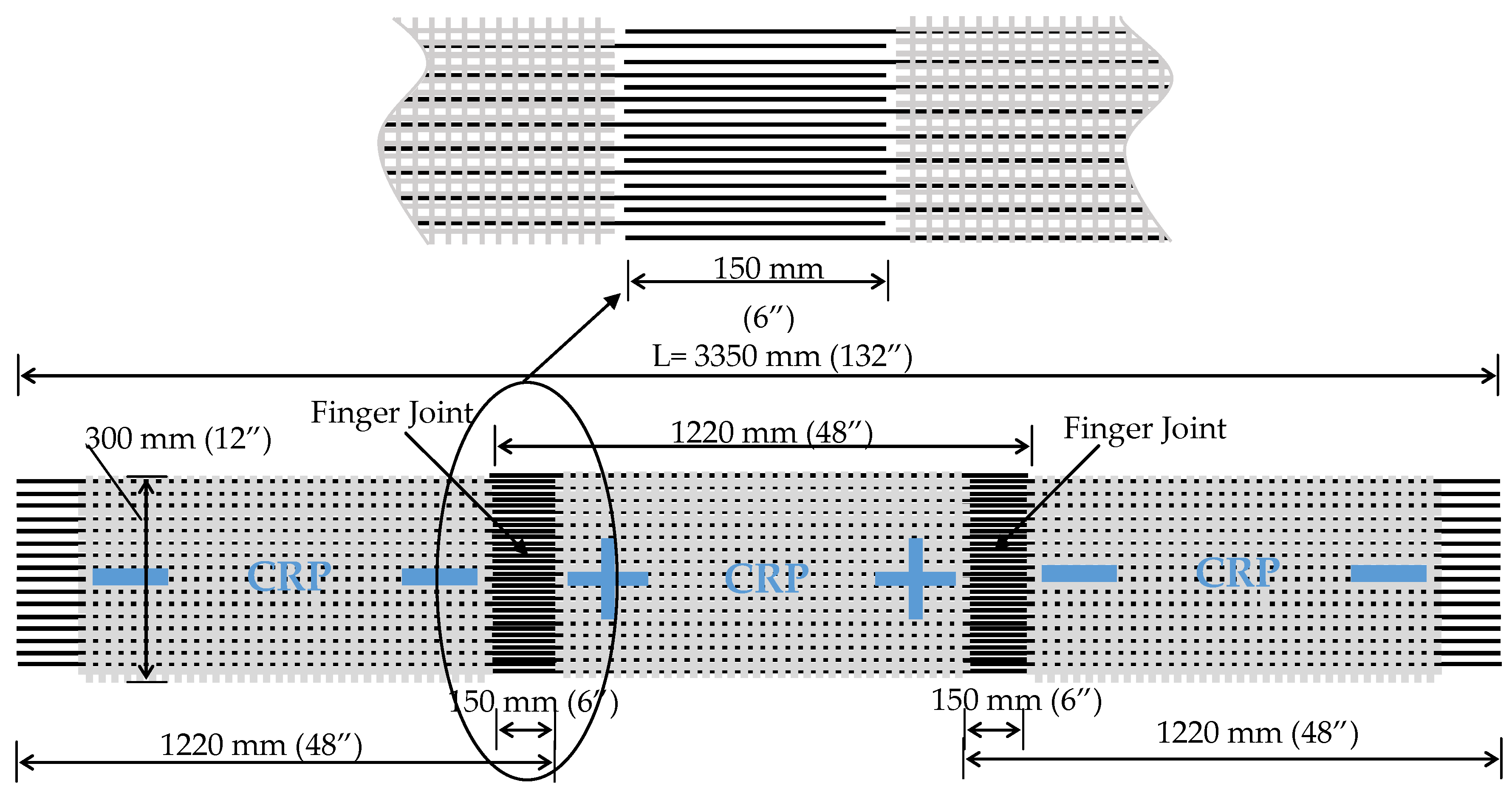
2. CFRP Rod Panels
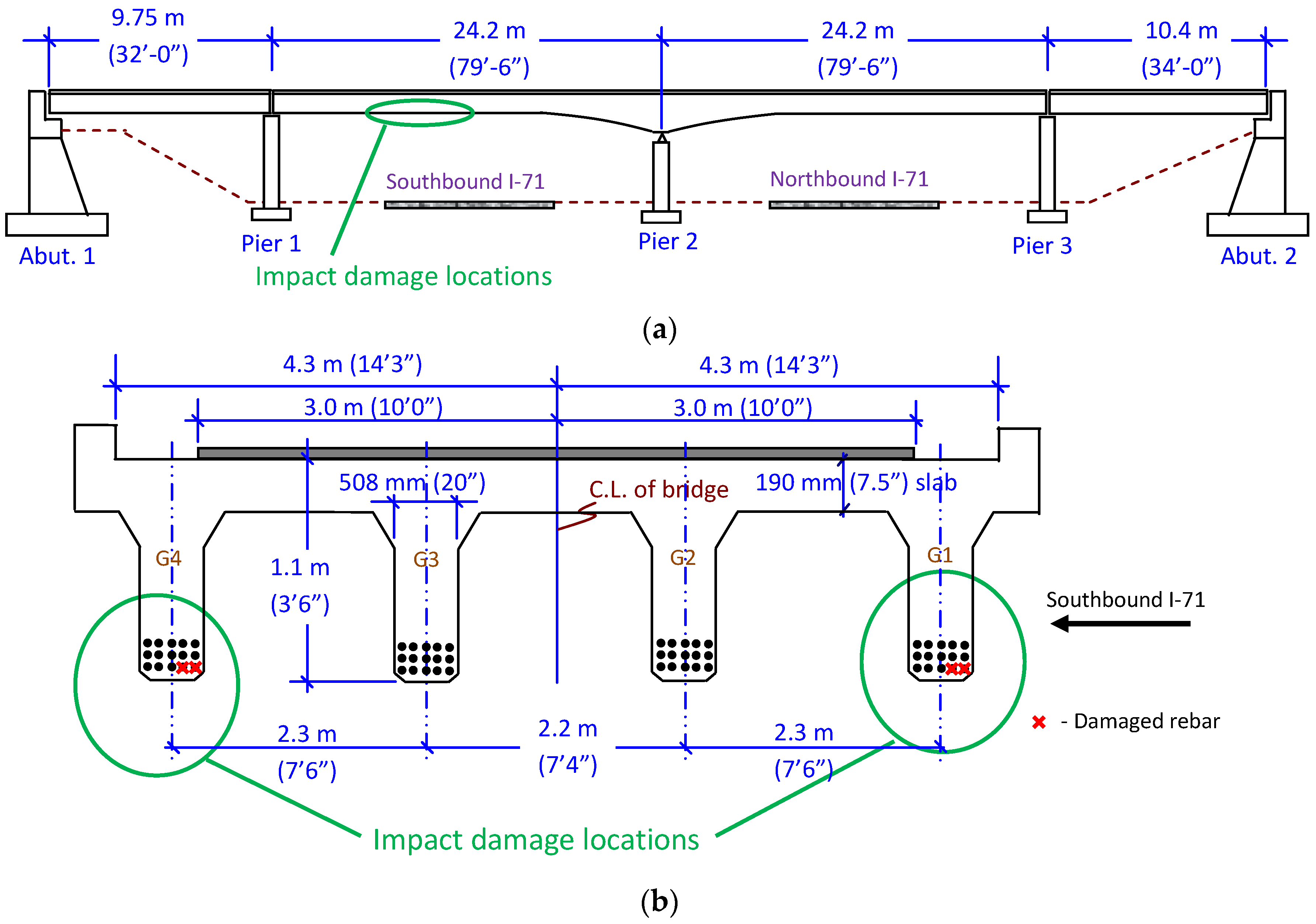
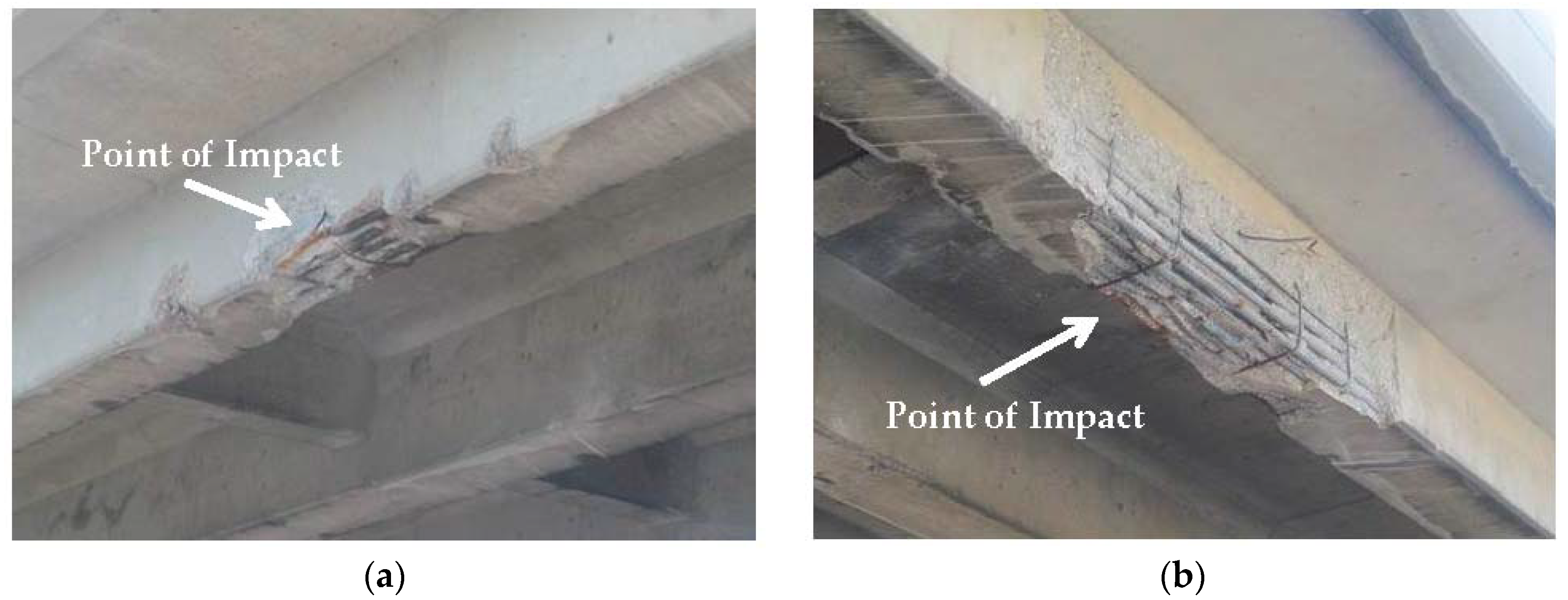
3. Bridge and Damage Details
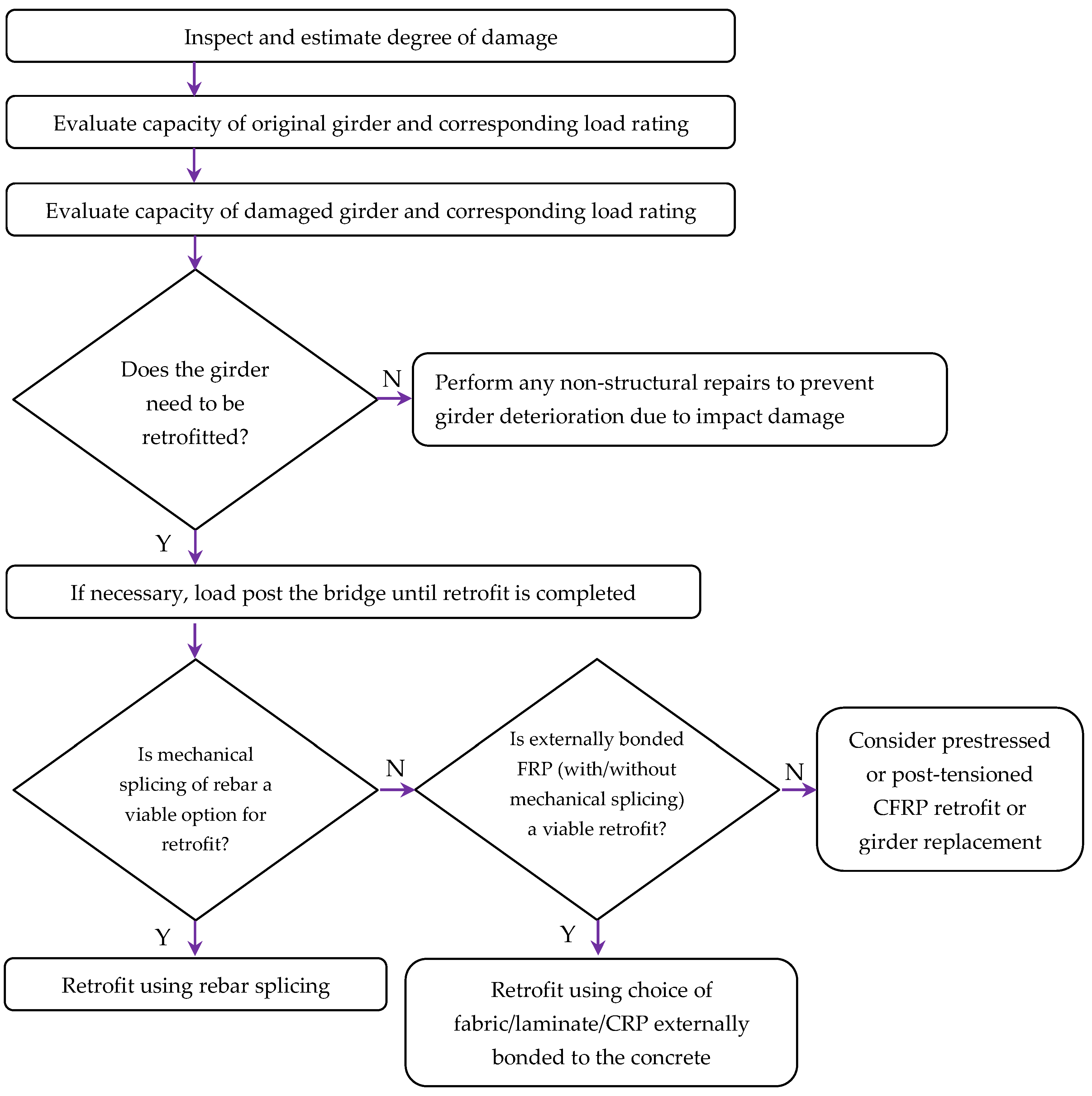
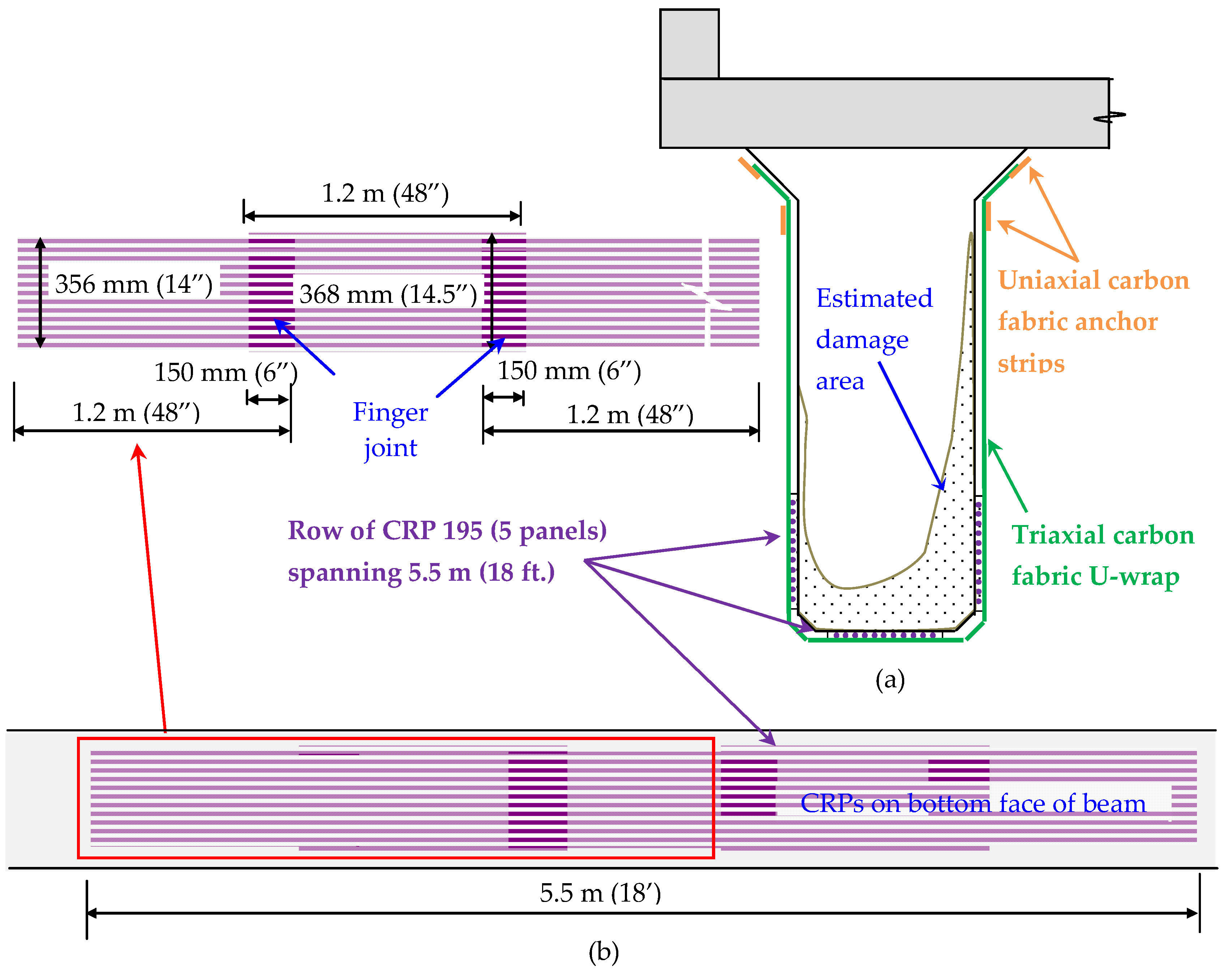
4. Design of CRP Retrofit
- Rr = factored resistance computed in accordance with AASHTO LRFD Section 5
- ηi = 1.0
- DC = force effects due to components and attachments
- DW = force effects due to wearing surface and utilities
- LL = force effects due to live loads
- IM = force effects due to dynamic load allowance
- Rn = nominal strength of member
- φ = strength reduction factor
- SDL = dead load effects
- SLL = live load effects
- f’c = Compressive strength of concrete in MPa (psi)
- n = Number of plies of FRP
- Ef = Tensile modulus of elasticity of FRP in MPa (psi)
- tf = Nominal thickness of one ply of FRP reinforcement in mm (in)
- εfu = design rupture strain of FRP reinforcement (mm/mm) (in/in)
- fy = Yield strength of steel rebar in MPa (psi)
- As-d = Damaged rebar area in mm2 (in2)
- Sr = Rod spacing of CRP panel in mm (in)
- Ar = CFRP rod area in mm2 (in2)
5. CRP Retrofit Analysis
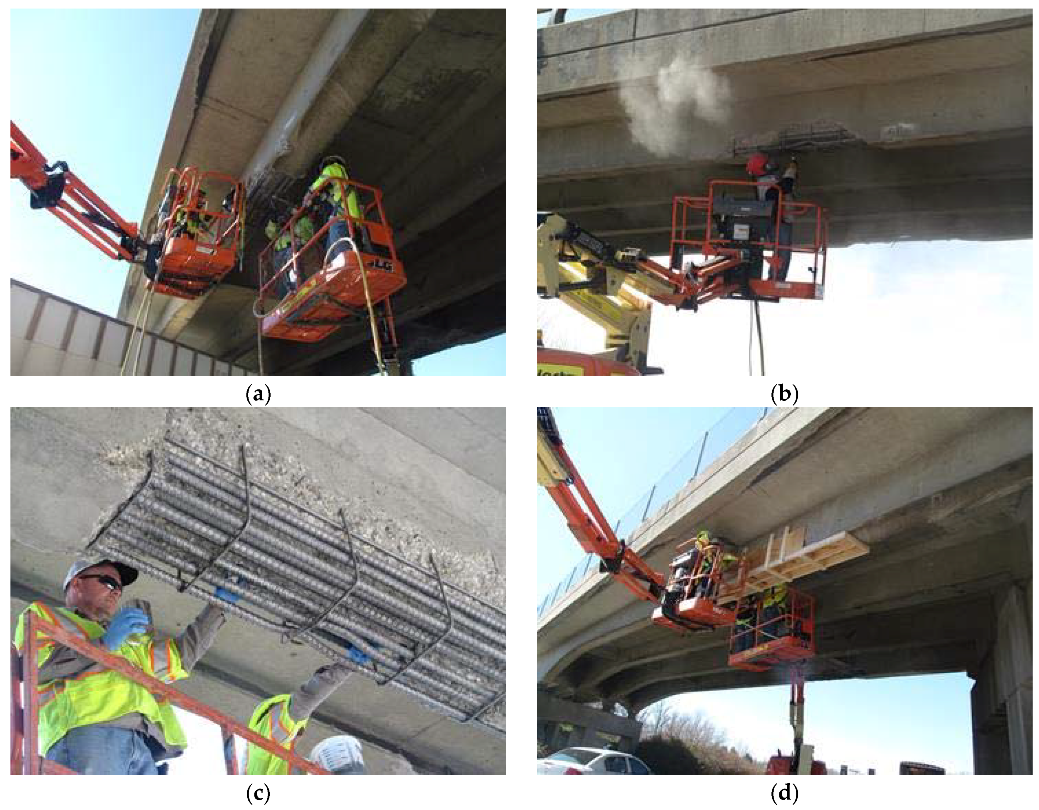
6. Retrofit Construction
7. Conclusions
- An initial estimate of the CRP size needed to replace damaged rebar can be made by calculating an equivalent axial stiffness, where the AASHTO debonding strain limits are utilized to estimate the CRP capacity.
- Although CRPs are experimentally shown to have a higher debonding strain than EB-CFRP, until additional experimental data is available, designs for strengthening RC bridge girders using CRPs should be conservatively based on AASHTO guidelines for EB-CFRP.
- The amount of strengthening that can be achieved using CRP may be limited by the available concrete bond area. In the future, this may be offset by increased debonding strain limits based on additional laboratory tests. Larger rods and higher modulus rods should be evaluated for their applicability in increasing the CRP capacity.
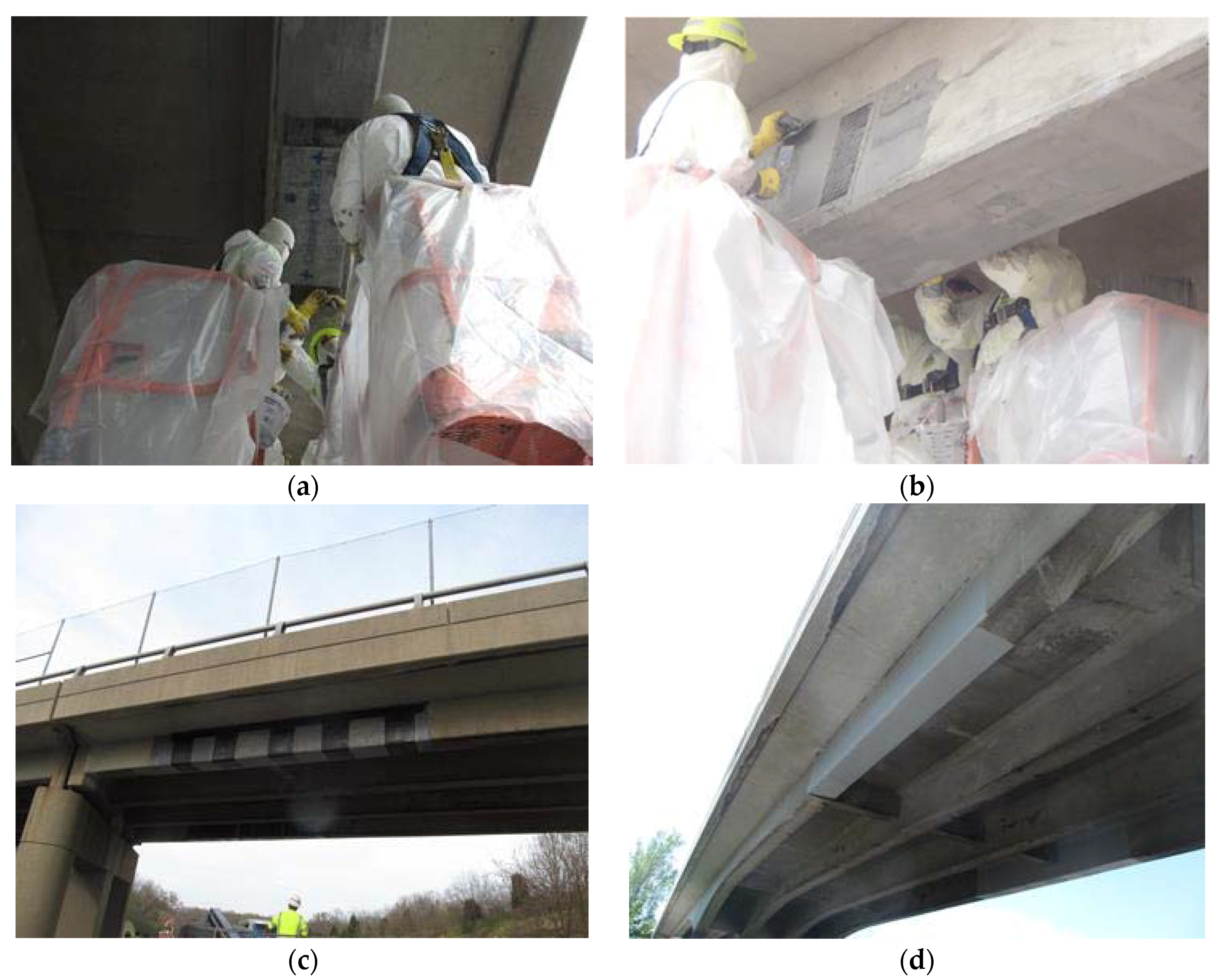
- As demonstrated by this project, the CRP application can be carried out by a two-person crew working from a mobile work platform/man-lift. This reduces the amount of manpower and equipment typically required with EB-CFRP. Additional crew members and construction equipment can be used to expedite the repair, especially when repairs are impacting congested roadways.
- The modular construction of the CRP, which gives crews the ability to halt strengthening after any CRP application, and resume at a later date, provides a significant advantage when working on bridges over multi-lane roadways. This may also be advantageous when strengthening long spans with limited construction access, such as those over waterways.
Author Contributions
Acknowledgments
Conflicts of Interest
Appendix A

| Girder and Section Properties of Damaged Girder | Metric Units | Inch-Pound Units |
| Clear span of girder (l) | 24.2 m | 79.6 ft |
| Effective width of deck (be) | 2.3 m | 90 in |
| Height of deck (hd) | 190 mm | 7.5 in |
| Height of girder (including deck) (hc) | 1.07 m | 42 in |
| Cracked section moment of inertia (Icr) | 0.0552 m4 | 132,678 in4 |
| Depth to cracked section N.A (kd) | 255 mm | 10.05 in |
| Girder section area (Ac) | 0.7516 m2 | 1165 in2 |
| Area of (remaining) steel (As) | 13,084 mm2 | 20.28 in2 |
| Depth to centroid of (remaining) steel (d) | 0.874 m | 34.4 in |
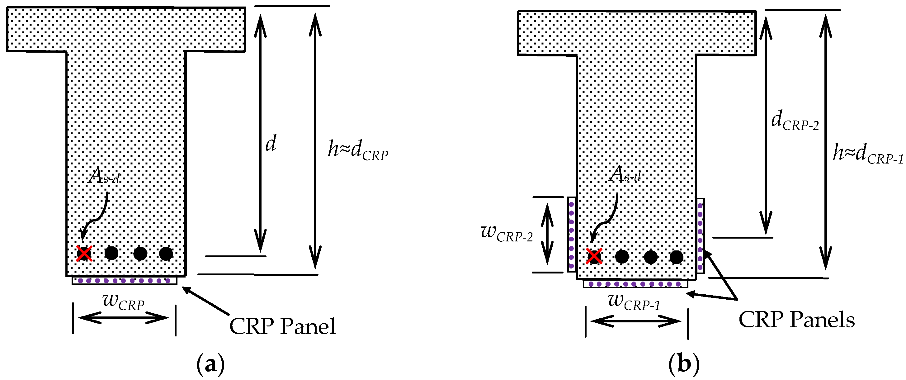
| Total FRP area of CRP (Af) Three 356 mm (14″) panels contain 38 rods each. Each rod is 12 mm2 (0.019 in2) | 1406 mm2 | 2.18 in2 |
| Equivalent depth to centroid all CRP (df) The two side panels are placed 25 mm (1 in) above the bottom surface to account for the chamfer. | 0.932 m | 36.7 in |
| Material Properties | Metric Units | Inch-Pound Units |
| Concrete modulus of elasticity (Ec) | 22.89 GPa | 3320 ksi |
| Concrete compressive strength (f’c) | 20.7 MPa | 3000 psi |
| Steel modulus of elasticity (Es) | 200 GPa | 29,000 ksi |
| Yield stress of steel (fy) | 276 MPa | 40 ksi |
| CRP FRP modulus of elasticity (Ef) | 134.4 GPa | 19,500 ksi |
| Ultimate FRP tensile strength (ffu*) | 2206 MPa | 320 ksi |
| Ultimate FRP rupture strain (εfu*) | 0.0164 mm/mm | 0.0164 in/in |
| Loading at Impact Location | Metric Units | Inch-Pound Units |
| Dead load moment (including barrier wall) (MDL) | 705 kN·m | 520 k·ft |
| Live load moment (edge beam) (MLL) | 988 kN·m | 729 k·ft |
| Impact Factor | 0.244 | 0.244 |
| Design | Metric Units | Inch-Pound Units |
| Step 1: Calculate CRP design material properties Since the CRP retrofit is on the bridge’s edge girder and will be directly exposed to the elements, an environmental reduction factor of 0.85 is used. ffu = 0.85ffu* εfu = 0.85εfu | 1875 MPa 0.0139 mm/mm | 272 ksi 0.0139 in/in |
| Step 2: Existing state of strain at FRP installation (εbi) Assuming that the beam is uncracked, and only dead loads exist at the time of FRP application, the existing strain at the bottom of the girder (εbi) is calculated. | 0.00038 mm/mm | 0.00038 in/in |
| Step 3: Estimate depth to neutral axis (c) An initial assumption of the neutral axis depth (c) is taken as 20% of the height of the composite girder. c = 0.2 hc | 213 mm | 8.4 in |
| Step 4: Determine effective level of strain in CRP (εfe) The maximum strain that the CRP can reach is governed by the strain limits due to either concrete crushing (εcu = 0.003), FRP rupture or FRP debonding. | ||
| Debonding | 0.005 mm/mm | 0.005 in/in |
| FRP strain at concrete crushing | 0.0097 mm/mm | 0.0097 in/in |
| FRP strain at rupture εfu = 0.0139 | 0.0139 mm/mm | 0.0139 in/in |
| The effective level of strain in the CRP (εfe) is the lesser of the debonding strain (εfd = 0.005 mm/mm), FRP strain at concrete crushing (εfu = 0.097 mm/mm), and the rupture strain (εfu = 0.0139 mm/mm) from the material properties. Therefore, effective level of strain εfe = εfd | 0.0050 mm/mm | 0.0050 in/in |
| Step 5: Calculate the stress in the CRP (ff) The stress is calculated based on the linear stress-strain relationship: | 672 MPa | 97.5 ksi |
| Step 6: Calculate the strain in the concrete (εc) The strain in the concrete is calculated using similar triangles: | 0.0016 mm/mm | 0.0016 in/in |
| Step 7: Calculate the strain in the steel (εs) The strain in the steel rebars is calculated using similar triangles: | 0.00495 mm/mm | 0.00495 in/in |
| Step 8: Calculate the stress in the steel (fs) The stress is calculated based on bi-linear stress-strain relationship: | 276 MPa | 40 ksi |
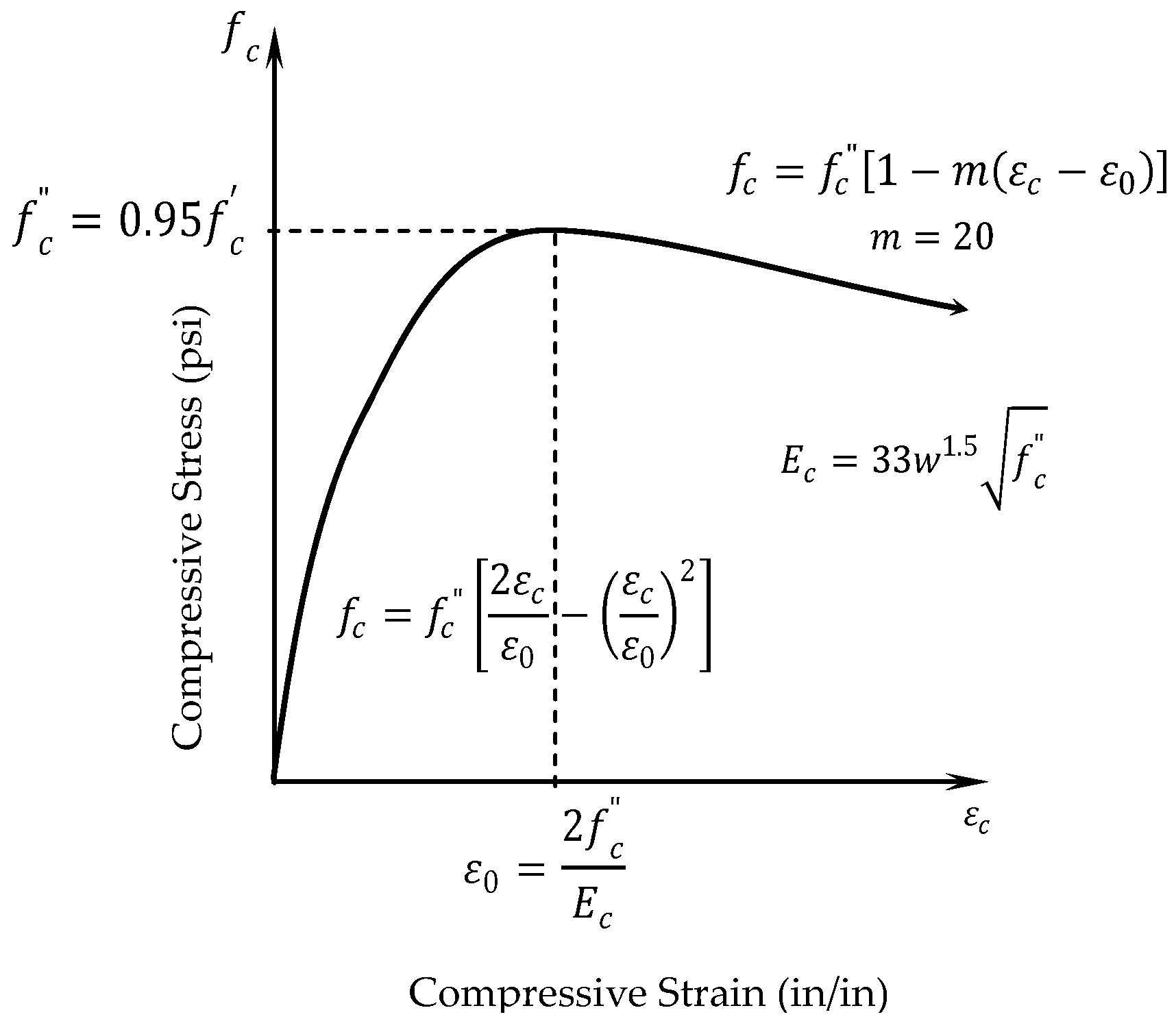
| Step 9: Calculate the equivalent concrete compressive stress block parameter (β2) This factor will be used to check the internal force equilibrium. | ||
| The strain at f’c is calculated (εo) | 0.00154 mm/mm | 0.00154 in/in |
| Average stress block parameter calculated from the parabolic stress-strain relationship for concrete: | 0.703 | 0.703 |
| Step 10: Calculate the internal force resultants and check equilibrium The calculated value is checked with the assumed value of c in Step 3. | 152 mm | 5.99 in |
| Step 11: Adjust c until force equilibrium is satisfied The value for c in Step 9 is within the deck (c ≤ hd) and is different from the value assumed in Step 3. Iterate starting from Step 3 until equilibrium is reached. Note: The AASHTO specifications may not be practical for the application of flanged sections when the neutral axis falls outside of the flange. | 173 mm | 6.83 in |
| Step 12: Calculate flexural strength components The contributions from the reinforcing steel and CRP to the beam flexural strength are calculated. The multiplier for locating the resultant of the compression force in the concrete (k2): | 0.367 | 0.367 |
| Reinforcing steel component (Mns) | 2923 kN·m | 2156 k·ft |
| FRP component (Mnf) | 820 kN·m | 605 k·ft |
| Step 13: Calculate flexural strength (Mr) An additional reduction factor φfrp = 0.85 is applied for flexural strength contribution of the CRP. | 3621 kN·m | 2671 k·ft |
| Step 14: Calculate design flexural strength (ϕMr) Design flexural strength (ϕMn) with ϕ = 0.9 reduction factor: Note: The ϕ factor is only applied to the steel component | 2752 kN·m | 2030 k·ft |
References
- Shanafelt, G.O.; Horn, W.B. NCHRP Report 271: Guidelines for Evaluation and Repair of Damaged Steel Bridge Members; Transportation Research Board of the National Academies: Washington, DC, USA, 1984. [Google Scholar]
- Shanafelt, G.O.; Horn, W.B. NCHRP Report 226: Damage Evaluation and Repair Methods for Prestressed Concrete Bridge Members; Transportation Research Board of the National Academies: Washington, DC, USA, 1980. [Google Scholar]
- Shanafelt, G.O.; Horn, W.B. NCHRP Report 280: Guidelines for Evaluation and Repair of Prestressed Concrete Bridge Members; Transportation Research Board of the National Academies: Washington, DC, USA, 1985. [Google Scholar]
- Harries, K.A.; Miller, R. NCHRP 20-07/Task 307: Updated Research for Collision Damage and Repair of Prestressed Concrete Beams; Transportation Research Board of the National Academies: Washington, DC, USA, 2012. [Google Scholar]
- Harik, I.; Peiris, A. Repair of impacted concrete bridge beams. In Proceedings of the 37th Symposium of the International Association for Bridge and Structural Engineering (IABSE-14), Madrid, Spain, 3–5 September 2014. [Google Scholar]
- Zobel, R.S.; Jirsa, J.O.; Fowler, D.W.; Carrasquillo, R.L. Evaluation and Repair of Impact-Damaged Prestressed Concrete Bridge Girders; FHWA/TX-97/1370-3F; Center for Transportation Research, the University of Texas: Austin, TX, USA, 1997. [Google Scholar]
- Feldman, L.R.; Jirsa, J.O.; Kowal, E.S. Repair of bridge impact damage. Concr. Int. 1998, 20, 61–66. [Google Scholar]
- American Concrete Institute (ACI) Committee 440, Guide to the Design and Construction of Externally Bonded FRP Systems for Strengthening Concrete Structures; ACI 440.2R-08; American Concrete Institute: Farmington Hills, MI, USA, 2008.
- American Association of State Highway and Transportation Officials (AASHTO). Design of Bonded FRP Systems for Repair and Strengthening of Concrete Bridge Elements, 1st ed.; American Association of State Highway and Transportation Officials (AASHTO): Washington, DC, USA, 2012. [Google Scholar]
- Japan Society of Civil Engineers (JSCE). Recommendation for Upgrading of Concrete Structures with Use of Continuous Fiber Sheets; Concrete Engineering Series 41; Japan Society of Civil Engineers (JSCE): Tokyo, Japan, 2001. [Google Scholar]
- International Federation for Structural Concrete (FIB) Task Group 9.3, Externally Bonded FRP Reinforcement for RC Structures; FIB Bulletin 14; FIB: Lausanne, Switzerland, 2001.
- Stallings, J.M.; Tedesco, J.W.; El-Mihilmy, M.; McCauley, M. Field Performance of FRP Bridge Repairs. ASCE J. Bridge Eng. 2000, 5, 107–113. [Google Scholar] [CrossRef]
- Choo, C.C.; Zhao, T.; Harik, H. Flexural retrofit of a bridge subjected to overweight trucks using CFRP laminates. Compos. Part B Eng. 2007, 38, 732–738. [Google Scholar] [CrossRef]
- National Cooperative Highway Research Program, Transportation Research Board (NCHRP). Updated Research for Collision Damage and Repair of Prestressed Concrete Beams; NCHRP 20-07/Task 307; NCHRP: Washington, DC, USA, 2012. [Google Scholar]
- Schiebel, S.; Parretti, R.; Nanni, A. Repair and Strengthening of Impacted PC Girders on Bridge A4845 Jackson County, Missouri; Report No. RDT01-017; Missouri Department of Transportation: Jackson City, MO, USA, 2001. [Google Scholar]
- Wipf, T.J.; Klaiber, F.W.; Rhodes, J.D.; Kempers, B.J. Effective Structural Concrete Repair—Volume 1 of 3: Repair of Impact Damaged Prestressed Concrete Beams with CFRP; Iowa DOT Project TR-428; Iowa Department of Transportation: Ames, IA, USA, 2004.
- Yang, D.; Merrill, B.D.; Bradberry, T.E. Texas’ use of CFRP to repair concrete bridges. In ACI SP 277: Recent Advances in Maintenance and Repair of Concrete Bridges; Kim, Y.J., Ed.; American Concrete Institute: Farmington Hills, MI, USA; pp. 39–57.
- Nanni, A. Strengthening of an Impact-Damaged PC Girder. Available online: https://cdn.ymaws.com/www.icri.org/resource/resmgr/crb/2004mayjun/CRBMayJune04_Nanni.pdf (accessed on 10 July 2018).
- Nanni, A.; Huang, P.C.; Tumialan, J.G. Strengthening of impact-damaged bridge girder using FRP Laminates. In Proceedings of the Ninth International Conference on Structural Faults and Repair, London, UK, 4–6 July 2001; Forde, M.C., Ed.; CD-ROM. Engineering Technics Press: Edinburgh, UK, 2001. [Google Scholar]
- Aidoo, J.; Harries, K.A.; Petrou, M.F. Full-scale experimental investigation of repair of reinforced concrete interstate bridge using CFRP material. ASCE J. Bridge Eng. 2006, 11, 350–358. [Google Scholar] [CrossRef]
- Pino, V.; Nanni, A.; Arboleda, D.; Robert-Wollmann, C.; Cousins, T. Repair of damaged prestressed concrete girders with FRP and FRCM composites. ASCE J. Compos. Constr. 2017, 21, 04016111. [Google Scholar] [CrossRef]
- Cerullo, D.; Sennah, K.; Hossein, A.; Lam, C.; Fam, A.; Tharmabla, B. Experimental study on full-scale pretensioned bridge girder damaged by vehicle impact and repaired with fiber-reinforced polymer technology. ASCE J. Compos. Constr. 2013, 17, 662–672. [Google Scholar] [CrossRef]
- Michels, J.; Michał Staśkiewicz, C.C.; Renata, K.; Yunus, E.H.; Masoud, M. Prestressed CFRP strips for concrete bridge girder retrofitting: Application and static loading test. J. Bridge Eng. 2016, 21, 04016003. [Google Scholar] [CrossRef]
- Kim, Y.J.; Green, M.F.; Fallis, G.J. Repair of bridge girder damaged by impact loads with prestressed CFRP sheets. ASCE J. Bridge Eng. 2008, 13, 15–23. [Google Scholar] [CrossRef]
- Casadei, P.; Galati, N.; Boschetto, G.; Tan, K.Y.; Nanni, A.; Galecki, G. Strengthening of impacted prestressed concrete bridge I-Girder using prestressed near surface mounted C-FRP Bars. In Proceedings of the 2nd International Congress, Fédération Internationale du Béton (FIB), Naples, Italy, 5–8 June 2006; pp. 1–10. [Google Scholar]
- Stallings, J.M.; Porter, N.M. Experimental investigation of lap splices in externally bonded carbon fiber-reinforced plastic plates. ACI Struct. J. 2003, 100, 3–10. [Google Scholar]
- Peiris, A.; Harik, I.E. CFRP rod panels for strengthening concrete bridges. Adv. Struct. Eng. 2018, 21, 557–570. [Google Scholar] [CrossRef]
- Peiris, A.; Harik, I.E. CFRP rod panels for strengthening concrete bridge components. In Proceedings of the Second Congress on Forensic Engineering and Sixth Congress on Collapses, Reliability and Retrofit of Structures (IF CRASC 15), Rome, Italy, 14–16 May 2015; pp. 533–541. [Google Scholar]
- Jawdhari, A.; Peiris, A.; Harik, I.E. Bond study on CFRP rod panels externally adhered to concrete. J. Compos. Constr. 2017, 21, 04016114. [Google Scholar] [CrossRef]
- Jawdhari, A. Behavior of RC Beams Strengthened in Flexure with Spliced CFRP Rod Panels. Ph.D. Thesis, University of Kentucky, Lexington, KY, USA, 2016. [Google Scholar] [CrossRef]
- American Association of State Highway and Transportation Officials (AASHTO). The Manual for Bridge Evaluation, 2nd ed.; AASHTO: Washington, DC, USA, 2016. [Google Scholar]
- American Association of State Highway and Transportation Officials (AASHTO). Standard Specifications for Highway Bridges, 17th ed.; AASHTO: Washington, DC, USA, 2002. [Google Scholar]
- Ford, J.S.; Chang, D.C.; Breen, J.E. Behavior of concrete columns under controlled lateral deformation. ACI J. 1981, 78, 3–20. [Google Scholar]


| Designation | Rod Diameter, dr | Rod Area, Ar | Rod Spacing, sr | Tensile Strength | Tensile Modulus | |||||
|---|---|---|---|---|---|---|---|---|---|---|
| mm | in | mm2 | in2 | mm | in | MPa | ksi | GPa | ksi | |
| CRP 070 | 1.98 | 0.078 | 3.08 | 4.78 × 10⁻³ | 6.5 | 0.250 | 2200 | 320 | 134 | 19,500 |
| CRP 195 | 3.96 | 0.156 | 12.33 | 19.11 × 10⁻³ | 9.5 | 0.375 | ||||
| Girder State | Moment Identification 1 | Moment Capacity | Concrete Strain | FRP Stress (ff/ffu) | HS20 Inventory Rating | HS20 Operating Rating | |
|---|---|---|---|---|---|---|---|
| kN·m | k·ft | mm/mm (in/in) | |||||
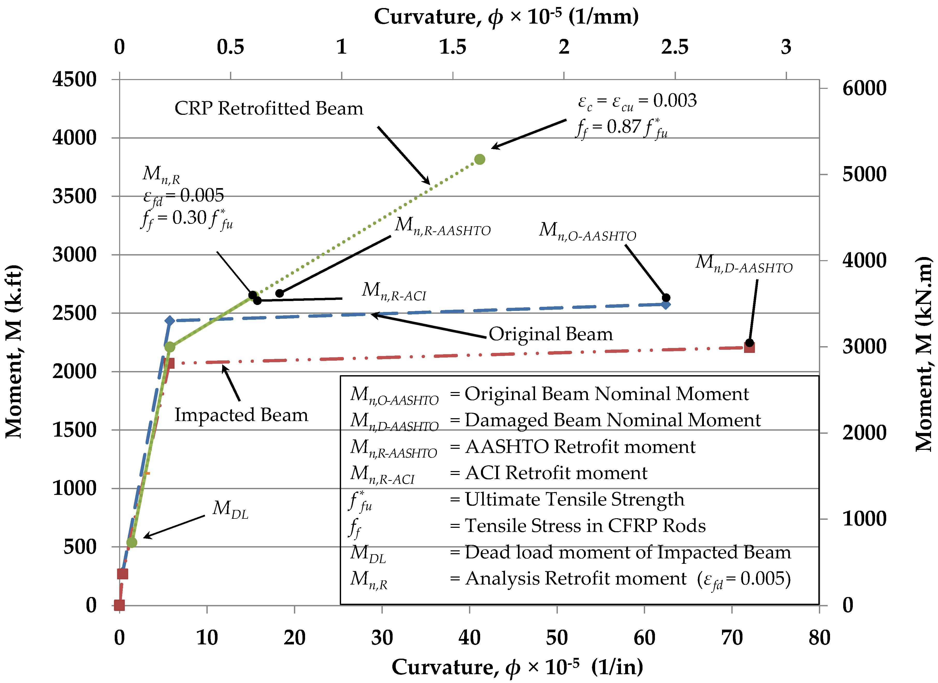
| Undamaged | Mn,O-AASHTO | 3523 | 2599 | 0.00300 | - | 1.08 | 1.80 |
| Damaged | MnD-AASHTO | 3015 | 2224 | 0.00300 | - | 0.87 | 1.45 |
| Retrofit | MnR-AASHTO | 3621 | 2671 | 0.00123 | 0.30 | 1.12 | 1.87 |
| MnR-ACI | 3555 | 2622 | 0.00107 | 0.27 | 1.09 | 1.82 | |
© 2018 by the authors. Licensee MDPI, Basel, Switzerland. This article is an open access article distributed under the terms and conditions of the Creative Commons Attribution (CC BY) license (http://creativecommons.org/licenses/by/4.0/).
Share and Cite
Peiris, A.; Harik, I. Design and Construction of CFRP Rod Panel Retrofit for Impacted RC Bridge Girders. J. Compos. Sci. 2018, 2, 40. https://doi.org/10.3390/jcs2030040
Peiris A, Harik I. Design and Construction of CFRP Rod Panel Retrofit for Impacted RC Bridge Girders. Journal of Composites Science. 2018; 2(3):40. https://doi.org/10.3390/jcs2030040
Chicago/Turabian StylePeiris, Abheetha, and Issam Harik. 2018. "Design and Construction of CFRP Rod Panel Retrofit for Impacted RC Bridge Girders" Journal of Composites Science 2, no. 3: 40. https://doi.org/10.3390/jcs2030040
APA StylePeiris, A., & Harik, I. (2018). Design and Construction of CFRP Rod Panel Retrofit for Impacted RC Bridge Girders. Journal of Composites Science, 2(3), 40. https://doi.org/10.3390/jcs2030040