Article

Mechanical Properties of Nacre-Like Composites: A Bottom-Up Approach

1
Department of Mechanical Engineering, Indian Institute of Technology Madras, Chennai 600036, India
2
Institute of General Mechanics, RWTH Aachen University, Templergraben 64, 52062 Aachen, Germany
*
Author to whom correspondence should be addressed.
J. Compos. Sci. 2020, 4(2), 35; https://doi.org/10.3390/jcs4020035
Submission received: 14 March 2020 / Revised: 1 April 2020 / Accepted: 2 April 2020 / Published: 7 April 2020

Abstract

:
Nacre is a highly organized hierarchical structure of the mineral and organic components at all scales down to the molecular-scale guided by organic molecules. The mechanical properties of the mineral component of nacre have been studied and well established for decades. In the present work, the shear modulus of the organic matrix of nacre was obtained using two of its important proteineous components, Perlucin and Lustrin A. The shear modulus value of the organic matrix was computed to be in the range of 1.25–1.45 GPa using atomistic molecular dynamics (MD) simulations. Moreover, finite element (FE) simulations were conducted on the three-dimensional (3D) models of the nacre-like composite while varying the relative composition of mineral and organic constituents. The nacre-like composite models with 10–20% by volume of organic part estimated high toughness. The exact optimum value will depend on the mechanical properties of the organic matrix used in the synthesis of nacre-like material. The study is an advancement in the modeling of nacre, sheds light on macroscale properties of nacre-like composites, and opens up new avenues for continuum studies of nacre mechanics, including its mysterious toughening mechanism.

Graphical Abstract

1. Introduction

Nacre, or mother of pearl as it is more commonly known, is a biomaterial derived from the inner part of the common mollusk shell. The material has high strength and toughness and is lightweight. The major reason nacre has such excellent properties can be attributed to its highly organized hierarchical structure as well as the self-sustaining properties of its organic matrix. These factors make nacre abalone an ideal biomaterial, whose properties will be useful in developing biomimetic technologies [1,2,3,4,5].
Nacre is composed of inorganic as well as organic layers. The inorganic layer is made up of calcium carbonate (CaCO 3 ), referred to as aragonite tablets, which are arranged in parallel to each other and in an overlapping pattern, which from the mesoscale appears as a columnar stack [2,6]. The aragonite tablets have high stiffness and low toughness [7,8,9,10]. However, the disadvantage of merely considering aragonite alone or as dry nacre, as it is referred to, is that such material fails in a brittle fashion [2,7,9,10,11,12]. Interspersed between the organic and inorganic layer is the intra-lamellar protein chitin, which from a nanoscale view, is visibly entwined within and around the aragonite platelets [2,13,14]. The organic layer is composed mainly of various proteins and glycoproteins that are randomly interspersed. This organic layer is, in part, responsible for generating the inorganic aragonite structure into the overlapping stacks via mineral bridges and growth enhancers (as well as through inhibition) [15]. This layer also possesses elastic properties that, when impinged upon, distributes the deformation along the membrane and reinforces the entirety of nacre in resisting crack formation [6,16,17]. Although nacre is composed of only 5% by organic matrix weight (the remaining 95% being that of the inorganic matrix), it follows that the organic matrix must be in part responsible for nacre’s unique strength, flexibility, and toughness, and, thus, deserves further attention [18,19].
Although the mechanical properties of the organic matrix are not fully understood, the basic structure and protein-specific properties are well-known. Several proteins make up the organic matrix of nacre abalone: Perlucin, Lustrin A, Perlwapin, Perlinhibin, and Perlustrin. Perlinhibin and Perlwapin are both inhibitory proteins, whose role is mainly to control unrestrained biomineralization within nacre. It is considered that they are playing a minor role with regards to the specific mechanical properties sought in this study [20,21]. Furthermore, there are only trace amounts of Perlinhibin per shell, supporting its role in contributing to nacre’s overall mechanical strength being minor [4,5]. The effects of Perlustrin are not unlike the process of bone growth. However, this is also a minor component of the organic matrix, as it is only approximately 10 μ g/shell [22]. Lustrin A is an abundant multi-domain protein, which consists of both proline- and cysteine-rich domains [23]. Additionally, Lustrin A has the largest discrete structural domain of 275 residues, of which 250 are either glycine (G) or serine (S). Shen et al. [24] and Zhang et al. [15] suggested that this additional domain has a high elastic property, which could prevent the fracture and separation within the mineral phase. Although Perlucin’s function is not yet fully understood, it also has a clear role in helping with biomineralization as well as being a promoter of calcium carbonate nucleation [22,25,26]. Therefore, it is clear that the organic matrix of nacre has two main proteineous components, Perlucin and Lustrin A, which are responsible for its pertinent mechanical properties. In the present work, a combination of both components was used in the MD simulations of the organic matrix.
MD simulations are capable of gaining insight into the deformation mechanisms from an atomistic-scale. Moreover, influences of the mechanical response of the organic matrix in biological minerals [19], as well as the role of the minerals to the proteins, have been investigated [27] using MD simulations. Furthermore, Atomic Force Microscopy (AFM) and inverse FE simulations were used to determine the elastic modulus of the organic matrix [28]. In the literature, due to various experimental techniques and computational methods, shear modulus of the organic matrix of nacre varies between 150 Mpa and 15 GPa [1,2,11,18,19,28,29,30,31,32,33,34]. Therefore, these studies evidently estimated a wide range of values of shear modulus.
In the past few decades, numerous studies have been done, including experimental, theoretical, and computational approaches, to unveil the mystery of the extraordinary mechanical properties of nacre. Special attention was given to the FE simulation techniques that measure the mechanical properties, as well as structural feature effects, such as the organic matrix properties [32,35], tablet interlocking [33], and surface waviness [11]. Furthermore, there have been many attempts made to replicate the structural organization of nacre in artificial composites [36,37,38,39]. The percentage of each of the constituents plays a significant role in determining the overall behavior of the nacre. A recent study on the interface strength of such composite materials has been performed to obtain optimal overall mechanical properties [40].
In this work, the shear modulus was computed using the organic matrix between two slabs of aragonite tablets. The mechanical properties obtained from the proposed molecular-based models can be used in the continuum models, which do not require any empirical parameters. In the continuum models of nacre, the percentages of the constituents are varied while keeping an intact brick–mortar structural arrangement. Furthermore, finite element (FE) simulations were conducted to study the macroscale properties, and comparisons were made with previous works in the literature. This work will contribute towards an improved understanding of nacre mechanics during deformation. The quantitative analysis of the viscoelastic properties of the organic matrix presents an essential step towards the development of multiscale modeling approaches of nacre.

2. Materials and Methods

2.1. Organic Matrix

The organic matrix of nacre consists primarily of proteins, glycoproteins, and chitin [22,41], which play a critical role in the functional and behavioral properties of nacre. Different proteins derived from various species of seashells are reported to have unique properties and functions in the nacre [42,43,44,45]. However, the biological properties and specific functions are not as much of a concern, and each of the isolated proteins was examined with regards to the overall mechanical impact of the organic matrix as an entity. Lustrin A (GS), isolated from haliotis rufescens, is the most widely studied, consisting of a domain with 275 residues, 250 of which are either glycine (G) or serine (S) [4,19]. Lustrin A is huge and has an overall structure that is not quite fully known. As a characteristic of its domain, Lustrin A is elastic (GS) x with (GSSS) y serine loops, which are assumed to protect aragonite during mineralization from fracture or separation [4,15]. Therefore, the GS domain was utilized as one of the organic matrix constituents in the study of the organic matrix’s mechanical behavior. The primary sequence of the GS domain is as follows:
GSGSGSGSGSGSGSSSSSSSGSTSGSGSGSGSGSSSGSGSGSSSASGSGSGSGSSSASGSGSSSGSG SGSSSGSGSGSGSGSGSSSGSSSVSNSWTGSGSSSGSGSGSSSWSGSSSGTGSGSSSWFGSGSSGS GSDSSSGSSSASGSGSSSGSSSGSGSGSSLWFGSGSSSGTGSGSSSGSSSGSGSDSSSGSTSGSSSGS GSASGSGTGS.
The second constituent of the nacre organic matrix is Perlucin (PR), which consists of 155 amino acids, including a glycosylated asparagine, which was isolated from the aragonite layer of the shell of the Mollusc Haliotis laevigata [25,26]. The amino-acid sequence of Perlucin is as follows:
GCPLGFHQNRRSCYWFSTIKSSFAEAAGYCRYLESHLAIISNKDEDSFIRGYATRLGEAFNYWL GASDLNIEGRWLWEGQRRMXYTNWSPGQPDNAGGIEHCLELRRDLGNYLWNDYQCQKPS HFICEKERIPYTNSLHANLQQRDSLHANLQQR.
The GS and PR domains were modeled using the primary sequences mentioned above. The fully stretched length of the GS and PR domains are 72 and 53 nm, respectively. Therefore, the resultant simulation systems for equilibration, as well as for pulling simulations, are not computationally feasible. Thus, both domains were modeled as three U-pins (three 180 turns), and were combined to make four independent peptide chains. The main goal of this work was to study the mechanical properties of the organic matrix, in particular the internal friction. This was accomplished by pulling domains in opposite directions with maximum contact of the residues. By dividing the GS and PR domains into four separate chains, this purpose is well served.
For the shear modulus calculation, 2GS-2PR (two units of GS and two units of PR) organic matrix was constructed by using the software Visual Molecular Dynamics (VMD) [46]. For subsequent MD simulations, the GROMACS 5.0.2 package was used [47] along with an OPLS-AA force field [48]. The organic matrix was placed between two aragonite tablets, as schematically shown in Figure 1. A system box was created for the shearing simulation with a size of 16.1×41.1×16.1 nm 3 . The combined system was solvated in TIP4P water [49] and had an overall system size of ∼1.2 million atoms.
In the shear simulations at a nanoscale level, the bottom aragonite tablet was constrained in all directions, and a constant velocity loading was applied on the top surface of the upper tablet (see Figure 1). The pulling force was applied by attaching one-dimensional harmonic springs with a force-constant of 1000 kJ/mol/nm 2 .

2.2. Aragonite

Aragonite is a brittle material with anisotropic properties. Its elastic modulus ranges between 25 and 170 GPa, depending on the loading direction [50,51]. In the tensile test, the load on aragonite platelets was majorly in a longitudinal plane and almost uniform on the transverse plane. The predicted elastic modulus and Poisson’s ratio for the load in a longitudinal plane were 107 GPa and 0.25, respectively [52]. The yield strength of aragonite was found to be 160 MPa [11].

2.3. Construction of 3D FE Model

For the construction of 3D FE models, first, a unit two-dimensional (2D) hexagonal plate of aragonite was constructed, which was surrounded by a 2D layer of the organic matrix (inter-tabular). The plate was later partitioned in a unique way to build the brick and mortar structure of the nacre. The 2D plate has a mesh with quadrilateral elements in an organized pattern. This mesh structure was replicated over the desired 2D surface and hence completed the plan of the model. Then, the 2D elements were extruded to generate 3D eight-noded elements with the desired element size perpendicular to the plane direction. Similarly, the other two lamellae of aragonite and the inter-tabular organic matrix were created. The elements of middle lamella were re-organized into the aragonite and organic components to generate the brick and mortar structure. The inter-lamellar and inter-tabular gaps were varied to get the composite material with the different volume fractions of the constituents of the nacre.
The composite model was fixed at one end and pulled from the other end (see Figure 2b). The displacement curve was chosen to be a scaled form of sigmoid function in time. This reduced the possibility of impulsive force at the beginning and end of the simulation. All the simulations were performed using an explicit integration finite element (FE) solver LS-DYNA (version: ls971 R7.1.1. Livermore Software Technology Corporation: Livermore, CA, USA) [53,54].
The oriented crack and plastic kinematic material models were used to set the material properties of the aragonite and organic matrix, respectively. The oriented crack material model enabled the use of maximum principal stress theory, Equation (1), as the failure criteria for aragonite. However, this material model came with a restriction for the solid elements to be of type-1, i.e., only one integration point was defined per element. The fracture plane was perpendicular to the direction of maximum principal stress. Once the material failed along a plane, the normal and shear stresses on it were gradually reduced to zero over some time steps. The gradual reduction was there to avoid ringing in the model due to the otherwise sudden fracture.
f ( σ , σ y 0 ) = max σ I , σ I I , σ I I I σ y 0 < 0 for elastic loading > 0 brittle failure
The organic matrix was modeled as a bilinear elastoplastic material. Due to the large elastic deformation, the failure criterion for the organic matrix was not considered. The plastic kinematic material model provided a parameter β [ 0 , 1 ] , which was used to set constitutive laws with a combination of kinematic and isotropic plasticity. In this work, the isotropic model ( β = 1 ) was used. The material model used standard elastic predictor and plastic corrector method to incorporate the plastic behavior of the organic matrix.
σ ^ i j n + 1 = σ i j n + λ δ i j Δ ϵ k k e l + 2 μ Δ ϵ i j e l
S ^ i j n + 1 = σ ^ i j n + 1 1 3 δ i j ( σ ^ k k n + λ δ k k Δ ϵ k k e l + 2 μ Δ ϵ k k e l )
Equation (2) is called the elastic predictor equation and represents the discretization of the deformation process. Equation (2) predicts the stress state ( σ ^ y ) by assuming the increment in strain ( Δ ϵ i j ) to be total elastic. Hence, the superscript e l is used to distinguish the assumed elastic strain from the actual strain. λ and μ are, respectively, the first and second Lame’s parameters. The deviatoric components ( S ^ i j n + 1 ) of stress and von Mises stress ( σ ^ e q n + 1 ) are computed using Equation (3). It should be noted that the ^ symbols are used to distinguish predicted quantities from the actual quantities.
f ( σ , σ y ) = σ ^ e q n + 1 σ y < 0 for elastic loading > 0 for plastic hardening and yielding
The yielding criterion is checked using the flow rule given in Equation (4). If the material yields locally, Equations (5)–(7) are solved iteratively to obtain the increment in equivalent plastic strain. In Equation (7), H, E t , and E are the tangent modulus, hardening modulus, and the elastic modulus of the organic matrix, respectively.
Δ ϵ e f f p = f ( σ , σ y ) 3 μ + H
ϵ e f f p , n + 1 = ϵ e f f p , n + Δ ϵ e f f p , ϵ e f f p , n = 0 t n 2 3 ϵ ˙ i j p ϵ ˙ i j p 1 2 d t
σ y = σ y 0 + H ϵ e f f p , H = E t E E E t
σ i j n + 1 = σ ^ i j 3 μ Δ ϵ e f f p σ e q S i j ^ .
After this, the total increment of the current step is split into its elastic and plastic part, and the other physical quantities such as actual stress ( σ i j ) and yield stress ( σ y ) are updated using Equations (7) and (8), respectively, to get the actual values.

3. Results and Discussion

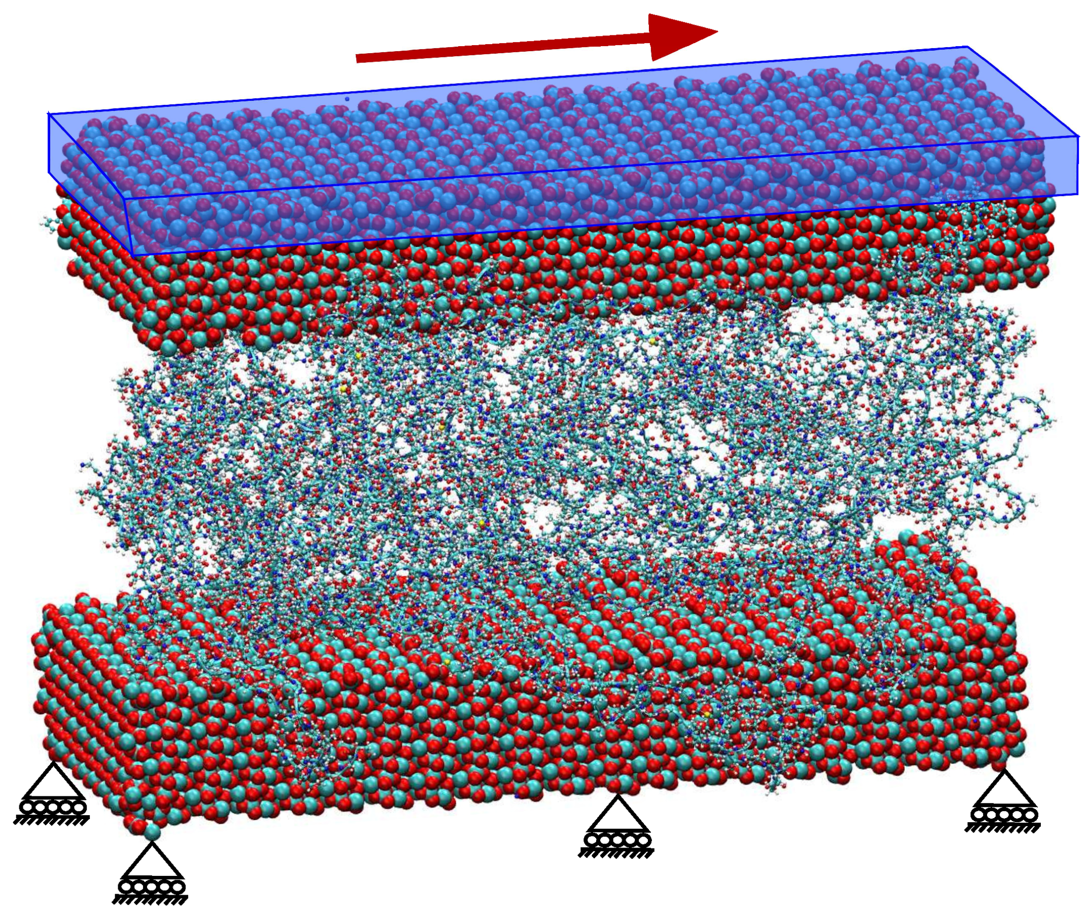
3.1. Shear Modulus of Organic Matrix

In our previous work, the rate-dependent behavior of the amorphous phase and viscous friction between the crystalline and amorphous phase of dragline silk were investigated using MD simulations [55,56]. In the present work, the 2GS-2PR simulation models were considered for computing the shear modulus. Figure 3 shows a shear stress–strain curve with snapshots of the shearing of the organic matrix. Shear stress was calculated from the applied shear force on the top aragonite tablet using harmonic spring and tablet contact area with the organic matrix. Shear strain was calculated from the lateral displacement of the center of mass of the aragonite tablets and vertical distance between them, i.e., the height of the organic matrix. In the combined model simulations, initially, much resistance offered from the interactions between the tablet and organic matrix resulted in a negligible shear strain. Therefore, initially, a vertical line (black colored line in Figure 3) in the shear stress–strain curve was observed.
The shear modulus is defined as the slope of the shear stress–strain curve. The calculation of one of the typical simulation example is shown in Figure 3. The computed shear modulus is 1.387 GPa. The shear modulus can alternatively be calculated using shear stress–strain curves obtained from the sliding of polypeptide chains.
The shear modulus value for the organic matrix was computed from a number of MD simulations to be in the range of 1.25–1.45 GPa. The value of the shear modulus allowed us to study the influence of the organic matrix on the mechanical properties of nacre using FE simulations.

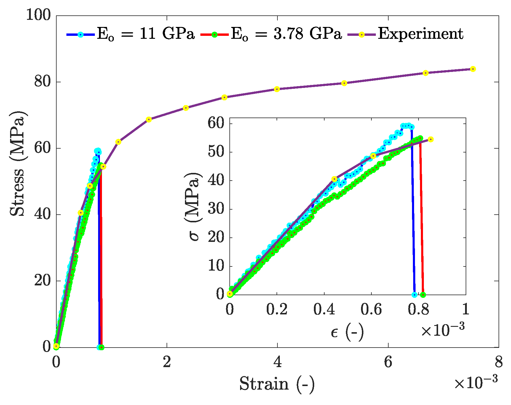
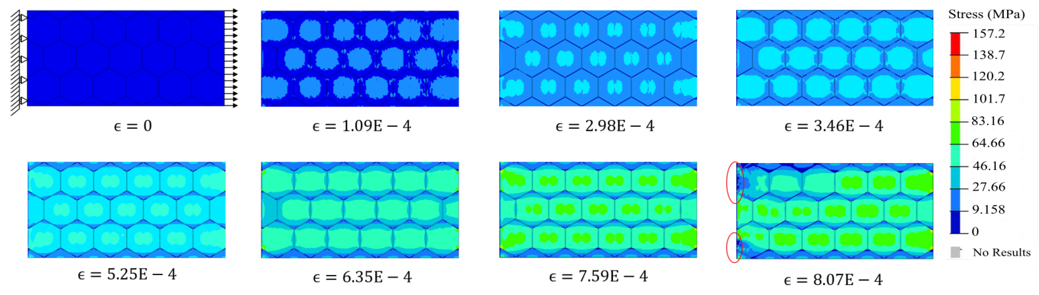
3.2. Stress–Strain Response of the 3D FE Nacre Models

Finite element simulations were conducted for two values of elastic modulus of the organic matrix. The shear modulus of 1.387 GPa obtained from MD simulations was converted to the elastic modulus of 3.78 GPa by using the Poisson’s ratio of the organic matrix as 0.36. Another set of simulations were run for Eo = 11 GPa [28]. Nominal stress and strain values were computed at all the time steps and for all the simulations. Stress was computed by summing the reaction forces over the pulled nodes and dividing the force by the initial area of cross-section. The strain was directly computed from dividing the applied displacement by the initial longitudinal length of the model. The toughness value was found by numerically integrating the area under the stress-strain curve.
The stress–strain curves obtained from FE simulations were found to be in close agreement with the experimental result [11] (see Figure 4). Figure 5 shows the distribution of maximum principal stress during the loading process. The initial increase in stress was observed to be at the center of the aragonite tablets. As can be observed from the successive contours in Figure 5, the rise in stress, due to load increments, propagated from the center of aragonite tablets towards the respective peripheries of the tablets.
It was found that the composite models with the organic matrix of 5% and 10% for Eo = 3.78 GPa as well as 5%, 10%, and 20% for Eo = 11 GPa showed yielding behavior characteristic (see Figure 6). The yielding in these cases was the consequence of fracture of aragonite as the local maximum principal stress in it reached the yield strength of 160 MPa. On the contrary, the remaining cases (generally with a comparatively higher percentage of the organic matrix) did not show any yielding behavior. This phenomenon can be attributed to the high percentage of the organic matrix. With the increase in the volume percentage of the organic matrix, the strain in the mineral component decreased as the total strain along the direction of the load had to be consistent with the externally applied displacement. The low strain values in aragonite resulted in a fall in the stress as well. Therefore, the stress in aragonite platelets did not reach the critical failure value (yield strength) for a high percentage of the organic matrix. It suggests that increasing the percentage of the organic matrix would delay the yielding/fracture and, thus, would increase the toughness of the composites. However, the decrease in global maximum stress (tensile strength) in the composite with the increased percentage of the organic matrix would reduce the toughness as well. Therefore, the change in the toughness of the composite by increasing the volume fraction of the organic matrix was determined by the two opposing factors: (i) delayed failure; and (ii) fall in yield strength.
The effective elastic modulus of nacre-like composite decreases with an increase in the volume percentage of the organic matrix. The effective elastic modulus of the composite for Eo = 3.78 GPa was lower than the case where Eo = 11 GPa for a fixed volume percentage of the organic matrix (see Figure 7). It was found that there was a nearly linear decline in the elastic modulus as the organic matrix percentage increased.

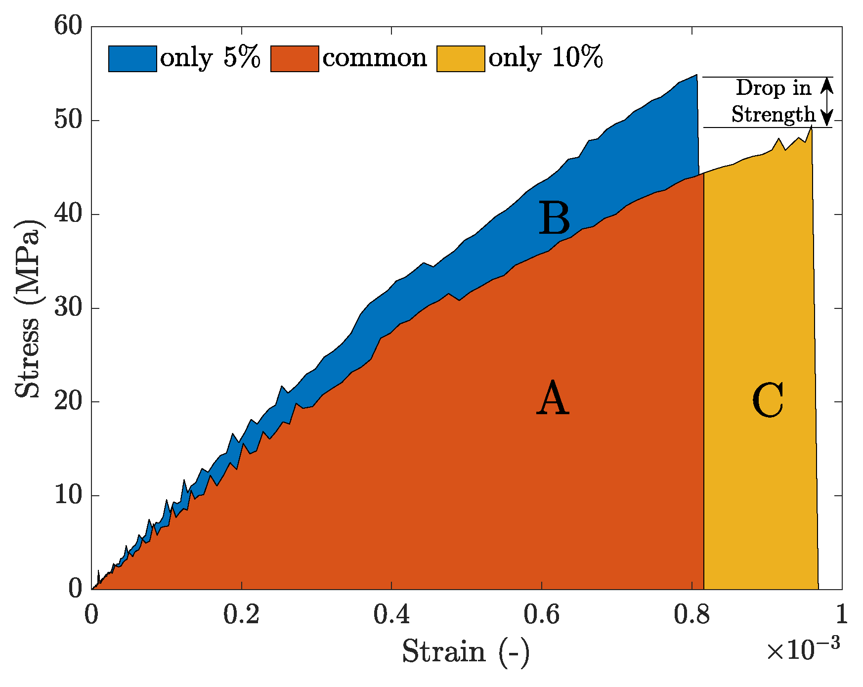
3.3. Toughness–Strength Trade-Off

The toughness of nacre-like composites showed a downward parabolic variation for both high and low values of Eo with changes in the percentage of the organic matrix (see Figure 8a). The toughness of the composite for both low and high elastic modulus of the organic matrix increased as organic matrix fraction increased from 5% to around 10%. The rise in the toughness of the composite with a lower elastic modulus of the organic matrix was more than that of composite with higher elastic modulus. The value remained more or less constant, with an increase in the organic matrix volume fraction from 10% to 20% and from 10% to 30% for Eo = 3.78 GPa and Eo = 11 GPa, respectively. Beyond 20% for Eo = 3.78 GPa and 30% for Eo = 11 GPa, the toughness declined significantly. Therefore, an optimum value of toughness was expected somewhere between 10% and 20% of the organic matrix. Moreover, as shown in Figure 8, for 10–20% of the organic matrix, the toughness of composite with Eo = 3.78 GPa was higher than that of composite with Eo = 11 GPa, suggesting that low elastic modulus (∼3.78 GPa) of the organic matrix is desired for designing a tough composite.
The maximum nominal stress, a measurement of strength, declined rapidly (see Figure 8b) irrespective of the elastic modulus of the organic matrix. The strength for Eo = 3.78 GPa was always less than that of Eo = 11 GPa for all compositions of the organic matrix. Therefore, a low value of the elastic modulus of the organic matrix would also result in a decline in the strength of the composite.
In cases of both high and low values of organic matrix stiffness, it could be observed that the change in the toughness of the composite with the increasing percentage of the organic matrix was the result of two counteracting factors. The first one was the increase in yield/fracture strain, which tended to increase Area C (see Figure 9) under the strain–strain curve. However, the second factor was the tensile strength, which increased with a decrease in the percentage of the organic matrix. The rise in maximum stress resulted in an increase in the toughness value, i.e., Area B increased (see Figure 9). As long as the increase in the area due to delayed failure (Area C) is more than the decrease due to reduced strength (Area B), the toughness of the composite is going to increase. Therefore, the increase in toughness comes at the cost of a decrease in strength.
As shown in Figure 8, the toughness of the composite with Eo = 3.78 GPa was likely to be less than that of Eo = 11 GPa for 5% and lower composition of the organic matrix. However, the trend reversed as the percentage of organic matrix increased from 5% to 10%. This observation again suggests that the use of low stiffness organic matrix with its low percentage in the composition is not advisable for optimum toughness.

4. Conclusions and Future Work

The organic matrix of nacre abalone has two main constituents, Lustrin A and Perlucin. Here, it was found that the mechanical response is independent of the constituents themselves as well as the size of the organic matrix. The shear modulus of the organic matrix was obtained by performing the shearing of a bundle of organic polypeptide chains using MD simulations. The shear modulus value was computed to be in the range of 1.25–1.45 GPa. It is an essential mechanical property that can be used to perform complex FE simulations of nacre models, which may not be otherwise feasible in the laboratory-setting.
Moreover, the results obtained from the FE simulations of nacre were found to be in good agreement with the experiment. By varying the volume fractions of the constituents of the nacre, it was found that a higher toughness in the synthetic nacre-like composite can be achieved by increasing the volume fraction of the organic matrix. However, it would come at the cost of a decrease in yield strength. It was also found that comparatively lower elastic modulus of the organic matrix would result in higher optimum toughness of the nacre-like composite for 10–20% of the volume fraction of the organic matrix. For a high value of elastic modulus of the organic matrix (>11 GPa), the toughness value is expected not to vary much in the 0–30% volume fraction range of the organic matrix. Therefore, if a composite with high toughness is to be designed, an organic matrix of low elastic modulus, as well as an optimum volume fraction, must be selected.
This study is an advancement towards a physical structure-based model for nacre. The final aim of the ongoing effort in the field of nacre mechanics is to link the nanoscale structure mechanics of nacre to its macroscopic properties. A correct model of the nacre structural architecture and the use of best-estimated properties gives us valuable insights in order to design new nacre-inspired high-performance materials. As the current model does not reflect the plastic regime of nacre, improvements can be made by incorporating more features such as nano-asperities and the mineral bridges in the model. This can be achieved by stochastically placing the mineral bridges and nano-asperities in the inter-lamellar layers. Hence, a better model will help us to establish a more reliable relationship between the properties of the constituents of nacre to the macro properties of the composite, such as toughness and strength.

Author Contributions

Conceptualization, M.R. and S.P.P.; methodology, M.R. and S.P.P.; software, M.R. and S.P.P.; validation, M.R. and S.P.P.; formal analysis, M.R., S.P.P., and B.M.; investigation, M.R. and S.P.P.; data curation, M.R. and S.P.P.; writing—original draft preparation, M.R. and S.P.P.; visualization, M.R. and S.P.P.; and supervision, S.P.P. and B.M. All authors have read and agreed to the published version of the manuscript.

Funding

This research received no external funding.

Acknowledgments

We gratefully acknowledge the University Grants Commission (UGC) and the German Academic Exchange Service (DAAD) for the mobility funding under the joint program Indo-German Partnership in Higher Education between IIT Madras and RWTH Aachen University. The authors gratefully acknowledge the computing time granted by the JARA Vergabegremium and provided on the JARA Partition part of the supercomputer CLAIX at RWTH Aachen University.

Conflicts of Interest

The authors declare no conflict of interest.

References

  1. Jackson, A.P.; Vincent, J.F.V.; Turner, R.M. The Mechanical Design of Nacre. Proc. R. Soc. Lond. B Biol. Sci. 1988, 234, 415–440. [Google Scholar]
  2. Sun, J.; Bhushan, B. Hierarchical structure and mechanical properties of nacre: a review. RSC Adv. 2012, 2, 7617–7632. [Google Scholar] [CrossRef]
  3. Finnemore, A.; Cunha, P.; Shean, T.; Vignolini, S.; Guldin, S.; Oyen, M.; Steiner, U. Biomimetic layer-by-layer assembly of artificial nacre. Nat. Commun. 2012, 3, 966. [Google Scholar] [CrossRef] [PubMed] [Green Version]
  4. Zhang, N.; Chen, Y. Molecular origin of the sawtooth behavior and the toughness of nacre. Mater. Sci. Eng. C 2012, 32, 1542–1547. [Google Scholar] [CrossRef]
  5. Zhang, N.; Yang, S.; Xiong, L.; Hong, Y.; Chen, Y. Nanoscale toughening mechanism of nacre tablet. J. Mech. Behav. Biomed. Mater. 2016, 53, 200–209. [Google Scholar] [CrossRef] [Green Version]
  6. Barthelat, F.; Li, C.M.; Comi, C.; Espinosa, H.D. Mechanical properties of nacre constituents and their impact on mechanical performance. J. Mater. Res. 2006, 21, 1977–1986. [Google Scholar] [CrossRef] [Green Version]
  7. Patil, S.P.; Heider, Y.; Hernandez Padilla, C.A.; Cruz-Chú, E.R.; Markert, B. A comparative molecular dynamics-phase-field modeling approach to brittle fracture. Comput. Methods Appl. Mech. Eng. 2016, 312, 117–129. [Google Scholar] [CrossRef]
  8. Cruz-Chu, E.R.; Xiao, S.; Patil, S.P.; Gkagkas, K.; Gräter, F. Organic Filling Mitigates Flaw-Sensitivity of Nanoscale Aragonite. ACS Biomater. Sci. Eng. 2017, 3, 260–268. [Google Scholar] [CrossRef]
  9. Padilla, C.H.; Patil, S.; Heider, Y.; Markert, B. 3D modelling of brittle fracture using a joint all-atom and phase-field approach. GAMM-Mitteilungen 2017, 40, 91–101. [Google Scholar] [CrossRef]
  10. Patil, S.P.; Heider, Y. A Review on Brittle Fracture Nanomechanics by All-Atom Simulations. Nanomaterials 2019, 9, 1050. [Google Scholar] [CrossRef] [Green Version]
  11. Barthelat, F.; Espinosa, H.D. An Experimental Investigation of Deformation and Fracture of Nacre-Mother of Pearl. Exp. Mech. 2007, 47, 311–324. [Google Scholar] [CrossRef]
  12. Barthelat, F. Nacre from mollusk shells: a model for high-performance structural materials. Bioinspir. Biomim. 2010, 5, 035001. [Google Scholar] [CrossRef] [PubMed] [Green Version]
  13. Chen, P.Y.; Lin, A.Y.M.; Lin, Y.S.; Seki, Y.; Stokes, A.G.; Peyras, J.; Olevsky, E.A.; Meyers, M.A.; McKittrick, J. Structure and mechanical properties of selected biological materials. J. Mech. Behav. Biomed. Mater. 2008, 1, 208–226. [Google Scholar] [CrossRef]
  14. Katti, K.S.; Katti, D.R.; Mohanty, B. Biomimetic Lessons Learnt from Nacre. Biomim. Learn. Nat. 2010, 1, 193. [Google Scholar]
  15. Zhang, B.; Wustman, B.A.; Morse, D.; Evans, J.S. Model peptide studies of sequence regions in the elastomeric biomineralization protein, Lustrin A. I. The C-domain consensus-PG-, -NVNCT-motif. Biopolymers 2002, 63, 358–369. [Google Scholar] [CrossRef] [PubMed]
  16. Meyers, M.A.; Lin, A.Y.M.; Chen, P.Y.; Muyco, J. Mechanical strength of abalone nacre: Role of the soft organic layer. J. Mech. Behav. Biomed. Mater. 2008, 1, 76–85. [Google Scholar] [CrossRef]
  17. Meyers, M.; Lim, C.; Li, A.; Nizam, B.H.; Tan, E.; Seki, Y.; McKittrick, J. The role of organic intertile layer in abalone nacre. Mater. Sci. Eng. C 2009, 29, 2398–2410. [Google Scholar] [CrossRef]
  18. Currey, J.D.; Zioupos, P.; Peter, D.; Casinos, A. Mechanical properties of nacre and highly mineralized bone. Proc. R. Soc. Lond. B Biol. Sci. 2001, 268, 107–111. [Google Scholar] [CrossRef] [Green Version]
  19. Ghosh, P.; Katti, D.R.; Katti, K.S. Mineral Proximity Influences Mechanical Response of Proteins in Biological Mineral-Protein Hybrid Systems. Biomacromolecules 2007, 8, 851–856. [Google Scholar] [CrossRef]
  20. Mann, K.; Siedler, F.; Treccani, L.; Heinemann, F.; Fritz, M. Perlinhibin, a cysteine-, histidine-, and arginine-rich miniprotein from abalone (Haliotis laevigata) nacre, inhibits in vitro calcium carbonate crystallization. Biophys. J. 2007, 93, 1246–1254. [Google Scholar] [CrossRef] [Green Version]
  21. Treccani, L.; Mann, K.; Heinemann, F.; Fritz, M. Perlwapin, an abalone nacre protein with three four-disulfide core (whey acidic protein) domains, inhibits the growth of calcium carbonate crystals. Biophys. J. 2006, 91, 2601–2608. [Google Scholar] [CrossRef] [PubMed] [Green Version]
  22. Weiss, I.M.; Göhring, W.; Fritz, M.; Mann, K. Perlustrin, a Haliotis laevigata (Abalone) Nacre Protein, Is Homologous to the Insulin-like Growth Factor Binding Protein N-Terminal Module of Vertebrates. Biochem. Biophys. Res. Commun. 2001, 285, 244–249. [Google Scholar] [CrossRef] [PubMed]
  23. Smith, B.L.; Schäffer, T.E.; Viani, M.; Thompson, J.B.; Frederick, N.A.; Kindt, J.; Belcher, A.; Stucky, G.D.; Morse, D.E.; Hansma, P.K. Molecular mechanistic origin of the toughness of natural adhesives, fibres and composites. Nature 1999, 399, 761–763. [Google Scholar] [CrossRef]
  24. Shen, X.; Belcher, A.M.; Hansma, P.K.; Stucky, G.D.; Morse, D.E. Molecular cloning and characterization of lustrin A, a matrix protein from shell and pearl nacre of Haliotis rufescens. J. Biol. Chem. 1997, 272, 32472–32481. [Google Scholar] [CrossRef] [PubMed] [Green Version]
  25. Weiss, I.M.; Kaufmann, S.; Mann, K.; Fritz, M. Purification and characterization of perlucin and perlustrin, two new proteins from the shell of the mollusc Haliotis laevigata. Biochem. Biophys. Res. Commun. 2000, 267, 17–21. [Google Scholar] [CrossRef]
  26. Mann, K.; Weiss, I.M.; André, S.; Gabius, H.J.; Fritz, M. The amino-acid sequence of the abalone (Haliotis laevigata) nacre protein perlucin. Detection of a functional C-type lectin domain with galactose/mannose specificity. Eur. J. Biochem. 2000, 267, 5257–5264. [Google Scholar] [CrossRef]
  27. Ghosh, P.; Katti, D.R.; Katti, K.S. Mineral and Protein-Bound Water and Latching Action Control Mechanical Behavior at Protein-Mineral Interfaces in Biological Nanocomposites. J. Nanomater. 2008, 2008, 1–8. [Google Scholar] [CrossRef] [Green Version]
  28. Xu, Z.H.; Yang, Y.; Huang, Z.; Li, X. Elastic modulus of biopolymer matrix in nacre measured using coupled atomic force microscopy bending and inverse finite element techniques. Mater. Sci. Eng. C 2011, 31, 1852–1856. [Google Scholar] [CrossRef]
  29. Currey, J. Mechanical properties of mother of pearl in tension. Proc. R. Soc. Lond. B Biol. Sci. 1977, 196, 443–463. [Google Scholar]
  30. Vincent, J.F.; Currey, J.D. The Mechanical Properties of Biological Materials: Symposia of the Society for Experimental Biology, Number XXXIV [edited by JFV Vincent and JD Currey].; Cambridge University Press for the Society for Experimental Biology: Cambridge, UK, 1980. [Google Scholar]
  31. Weiner, S.; Traub, W.; Parker, S. Macromolecules in mollusc shells and their functions in biomineralization. Philos. Trans. R. Soc. Lond. B Biol. Sci. 1984, 304, 425–434. [Google Scholar]
  32. Katti, D.; Katti, K.; Sopp, J.; Sarikaya, M. 3D finite element modeling of mechanical response in nacre-based hybrid nanocomposites. Comput. Theor. Polym. Sci. 2001, 11, 397–404. [Google Scholar] [CrossRef]
  33. Katti, K.S.; Katti, D.R.; Pradhan, S.M.; Bhosle, A. Platelet interlocks are the key to toughness and strength in nacre. J. Mater. Res. 2005, 20, 1097–1100. [Google Scholar] [CrossRef]
  34. Lin, A.Y.M.; Meyers, M.A. Interfacial shear strength in abalone nacre. J. Mech. Behav. Biomed. Mater. 2009, 2, 607–612. [Google Scholar] [CrossRef] [PubMed]
  35. Katti, D.R.; Katti, K.S. Modeling microarchitecture and mechanical behavior of nacre using 3D finite element techniques Part I Elastic properties. J. Mater. Sci. 2001, 36, 1411–1417. [Google Scholar] [CrossRef]
  36. Bouville, F.; Maire, E.; Meille, S.; Van de Moortèle, B.; Stevenson, A.; Deville, S. Strong, Tough and Stiff Bioinspired Ceramics from Brittle Constituents. Nat. Mater. 2014, 13, 508–514. [Google Scholar] [CrossRef] [Green Version]
  37. Deville, S.; Saiz, E.; Nalla, R.; Tomsia, A. Freezing as a Path to Build Complex Composites. Science 2006, 311, 515–518. [Google Scholar] [CrossRef] [Green Version]
  38. Corni, I.; Harvey, T.J.; Wharton, J.A.; Stokes, K.R.; Walsh, F.C.; Wood, R.J.K. A review of experimental techniques to produce a nacre-like structure. Bioinspir. Biomim. 2012, 7, 031001. [Google Scholar] [CrossRef]
  39. Zhao, H.; Guo, L. Nacre-Inspired Structural Composites: Performance-Enhancement Strategy and Perspective. Adv. Mater. 2017, 29, 1702903. [Google Scholar] [CrossRef]
  40. Radi, K.; Jauffrès, D.; Deville, S.; Martin, C.L. Elasticity and fracture of brick and mortar materials using discrete element simulations. J. Mech. Phys. Solids 2019, 126, 101–116. [Google Scholar] [CrossRef] [Green Version]
  41. Zentz, F.; Bédouet, L.; Almeida, M.J.; Milet, C.; Lopez, E.; Giraud, M. Characterization and quantification of chitosan extracted from nacre of the abalone Haliotis tuberculata and the oyster Pinctada maxima. Mar. Biotechnol. 2001, 3, 36–44. [Google Scholar] [CrossRef]
  42. Walters, D.A.; Smith, B.L.; Belcher, A.M.; Paloczi, G.T.; Stucky, G.D.; Morse, D.E.; Hansma, P.K. Modification of calcite crystal growth by abalone shell proteins: an atomic force microscope study. Biophys. J. 1997, 72, 1425–1433. [Google Scholar] [CrossRef] [Green Version]
  43. Schäffer, T.E.; Ionescu-Zanetti, C.; Proksch, R.; Fritz, M.; Walters, D.A.; Almqvist, N.; Zaremba, C.M.; Belcher, A.M.; Smith, B.L.; Stucky, G.D.; et al. Does Abalone Nacre Form by Heteroepitaxial Nucleation or by Growth through Mineral Bridges? Chem. Mater. 1997, 9, 1731–1740. [Google Scholar] [CrossRef] [Green Version]
  44. Falini, G.; Albeck, S.; Weiner, S.; Addadi, L. Control of Aragonite or Calcite Polymorphism by Mollusk Shell Macromolecules. Science 1996, 271, 67–69. [Google Scholar] [CrossRef]
  45. Levi, Y.; Albeck, S.; Brack, A.; Weiner, S.; Addadi, L. Control Over Aragonite Crystal Nucleation and Growth: An In Vitro Study of Biomineralization. Chem. Eur. J. 1998, 4, 389–396. [Google Scholar] [CrossRef]
  46. Humphrey, W.; Dalke, A.; Schulten, K. VMD: visual molecular dynamics. J. Mol. Graph. 1996, 14, 33–38. [Google Scholar] [CrossRef]
  47. van der Spoel, D.; Lindahl, E.; Hess, B.; Groenhof, G.; Mark, A.E.; Berendsen, H.J. GROMACS: fast, flexible, and free. J. Comput. Chem. 2005, 26, 1701–1718. [Google Scholar] [CrossRef]
  48. Jorgensen, W.L.; Tirado-Rives, J. The OPLS [optimized potentials for liquid simulations] potential functions for proteins, energy minimizations for crystals of cyclic peptides and crambin. J. Am. Chem. Soc. 1988, 110, 1657–1666. [Google Scholar] [CrossRef]
  49. Jorgensen, W.L.; Chandrasekhar, J.; Madura, J.D.; Impey, R.W.; Klein, M.L. Comparison of simple potential functions for simulating liquid water. J. Chem. Phys. 1983, 79, 926–935. [Google Scholar] [CrossRef]
  50. Liu, L.G.; Chen, C.C.; Lin, C.C.; Yang, Y.J. Elasticity of single-crystal aragonite by Brillouin spectroscopy. Phys. Chem. Miner. 2005, 32, 97–102. [Google Scholar] [CrossRef]
  51. Levy, M.; Bass, H.; Keppens, V. Handbook of Elastic Properties of Solids, Liquids, and Gases; Academic Press: San Diego, CA, USA, 2001. [Google Scholar]
  52. Barthelat, F.; Espinosa, H.D. Elastic Properties of Nacre Aragonite Tablets. In Proceedings of the SEM Annual Conference and Exposition on Experimental and Applied Mechanics, Charlotte, NC, USA, 2–4 June 2003. [Google Scholar]
  53. Livermore Software Technology Corporation. LS-DYNA Keyword Users Manual; Livermore Software Technology Corporation: Livermore, CA, USA, 2010. [Google Scholar]
  54. Livermore Software Technology Corporation. Ls-Pre/Post; Livermore Software Technology Corporation: Livermore, CA, USA, 2011. [Google Scholar]
  55. Patil, S.P.; Markert, B.; Gräter, F. Rate-dependent behavior of the amorphous phase of spider dragline silk. Biophys. J. 2014, 106, 2511–2518. [Google Scholar] [CrossRef] [Green Version]
  56. Patil, S.P.; Xiao, S.; Gkagkas, K.; Markert, B.; Gräter, F. Viscous friction between crystalline and amorphous phase of dragline silk. PLoS ONE 2014, 9, e104832. [Google Scholar] [CrossRef] [PubMed] [Green Version]
Figure 1. Schematic representation of shearing of the organic matrix. Bottom tablet of aragonite is constrained in all directions, and velocity (red arrow) is applied on the upper surface of the top tablet (blue box).
Jcs 04 00035 g001
Figure 2. (a) Mesh partition pattern of a unit aragonite tablet surrounded by inter-tabular organic matrix; (b) boundary conditions; (c) 3D view of the nacre model; and (d) top view of the model resembling the brick and mortar structure.
Jcs 04 00035 g002
Figure 3. Shear stress versus shear strain curve for the combined model. The initial part of the curve (black) shows nearly no displacement of the upper aragonite tablet. Linearization of the shearing curve is shown with the blue dotted line. Snapshots show the shearing of the organic matrix taken at strains that are marked by arrows.
Jcs 04 00035 g003
Figure 4. Comparison of FE simulation results with experimental result [11] of 5% organic matrix for two different values of elastic modulus: Eo = 3.78 GPa and Eo = 11 GPa of organic matrix. Inset: Enlarged view of the stress-strain curves. Excellent agreement can be observed between the simulations and the experiment in the elastic region.
Jcs 04 00035 g004
Figure 5. Evolution of maximum principal stress with longitudinal strain increment. The failure is observed when local maximum principal stress reaches to 160 MPa at the fixed end of the composite as encircled in red. The contours are shown for Eo = 3.78 GPa and 5% organic matrix by volume.
Jcs 04 00035 g005
Figure 6. Stress–strain response of nacre-like composites for varying organic volume percentage. The considered elastic modulus of organic matrix are: (a) Eo = 3.78 GPa; and (b) Eo = 11 GPa.
Jcs 04 00035 g006
Figure 7. Trend of elastic modulus of the composites with varying percentage of the organic matrix.
Jcs 04 00035 g007
Figure 8. Trend of (a) toughness and (b) maximum stress with variation in percentage of the organic matrix.
Jcs 04 00035 g008
Figure 9. Trade-off between toughness and strength as the organic matrix percentage increases from 5% to 10%.
Jcs 04 00035 g009

