Abstract
Composite materials of poly(3,4-ethylenedioxythiophene) (PEDOT)/activated carbon (AC) were prepared by ‘in-situ’ polymerization and subsequently deposited by spray-coating onto a flexible electrolyte prepared in our laboratories. Two activated carbons were tested: a commercial activated carbon and a lab-made activated carbon from brewer’s spent grain (BSG). The porous and spongy structure of the composite increased the specific surface area, which helps to enhance the energy storage density. This procedure to develop conductive composite materials using AC prepared from biowaste has the potential to be implemented for the preparation of polymer-based conductive inks for further applications as electrodes in pseudocapacitors.
1. Introduction
Energy demand has drastically increased around the world with the growing population and due to the rapid development of wearable electronics and microelectronic devices [1]. Unfortunately, the use of renewable energies, such as solar and wind sources presents the inconvenience of its intermittent nature. In this context, energy storage devices have become a key academic and industrial research topic towards a low cost and zero environmental impact energy source, which can be supplied on demand [2]. As a consequence, there is a great interest on developing novel materials for energy storage devices using preferably low cost materials and sustainable methodologies [3,4].
During the past decade, the global supercapacitors market has been growing rapidly as an energy storage source compared to batteries [5]. In comparison to batteries, they are able to charge energy in a faster way and can have much more charge–discharge cycles. Most employed supercapacitors are known as electronic double-layer capacitors (EDLC) due to the electrical double layer generated during the charge process.
In order to increase the capacity of supercapacitors, different active materials have been used. Particularly, conjugated polymers (CPs) have shown promising characteristics as electrodes for supercapacitors. Unlike EDLC, the charge–discharge mechanism in these materials is due to the faradaic reactions, which occur on the bulk and surface between the electrode and the electrolyte [6]. This pseudo-capacitance gives the name of pseudocapacitors, where other materials such as metal oxides have been also used. These pseudocapacitors can be considered intermediate materials between batteries and EDLC in terms of capacity but with much lower cycles and lower power density compared to EDLC [7].
From the point of view of electrode design, diverse strategies can be found in the literature that increase the performance of energy storage devices [1,5,6,8,9]. One interesting approach to take advantage of the characteristics of EDLC-type systems and pseudocapacitors consist in the addition of carbon particles into the polymer matrix of CPs to obtain a composite material. An electrode made of poly(3,4-ethylenedioxythiophene) (PEDOT)–carbon composite exhibited high specific capacitance values and number of cycles due to the semiregular, macroporous nature of the electrode film [10,11,12,13,14,15]. These advances give a way for many other combinations of carbon-conducting polymer composites for energy storage and other applications.
During the last years, alternative carbon materials such as carbon nanotubes or graphene have been proposed as electrode materials for supercapacitors [8,9,14,16,17]. Very recently, Khasim et al. have developed a high performance and flexible supercapacitor using a conductive composite material composed of reduced graphene oxide (rGO) and PEDOT-PSS. A doped PEDOT–PSS:ethylene glycol/rGO composite film demonstrated improved electrochemical performances with specific capacitance of 174 F·g−1 and energy density of 810 W·h·kg−1 [18]. However, the relatively high price of graphene and the agglomeration of these particles have limited its scalability and application in commercial supercapacitors.
Currently, virtually all commercial supercapacitors devices use activated carbon (AC) mostly due to its low cost. Electrochemical performance of AC in the supercapacitors depends on multiple factors such as surface area, pore size and surface functionalities, which have a direct effect to achieve high capacitance, power density and high cycle numbers [19,20]. Despite the mentioned advantages of using activated carbon as active electrode material for supercapacitors, much lower capacity is achieved compared to batteries. Recently, Kaner and co-workers have demonstrated that laser scribing of standard activated carbon electrodes results in the formation of macroporous electrodes, allowing for a new generation of carbon supercapacitors with high areal capacitance (up to 379 mF·cm−2), specific power (up to 5.26 W·cm−3), specific energy (up to 9.05 mWh·cm−3) and low equivalent series resistance (1.6 Ω·cm2) [21].
Over the past two decades, recycling industrial biowaste as precursor of low cost fabrication of activated carbon has been implemented to boost circular economy and develop, among other materials, electrode material for supercapacitors [22,23,24,25,26,27,28,29]. Recently, some authors have used residues from the beer extraction processes or brewer’s spent grain (BSG) as a precursor material for obtaining activated carbon [30,31,32]. This type of biowaste, which has been generally used in the production of animal feed, has turned out to be good candidates for the development of electrode materials for EDLC performance in 0.1 M H2SO4 electrolyte solution, showing high specific capacitance values in the range from 128 to 188 F/g [33].
Moreover, due to the fast development of portable electronic devices, another important and desirable aspect in supercapacitors is flexibility, heading to flexible solid-state supercapacitors. By consequence, there is a need for the development of flexible electrodes and electrolytes, which can have these characteristics [18,34,35,36,37]. Very recently, Hsiao et al. prepared an activated carbon-coated flexible supercapacitor with a fibrous architecture using Tetrapanax papyrifer with a honeycomb-like structure acting as a frame, obtaining a capacitance of 83.9 mF/cm2 and excellent mechanical flexibility [38]. Gupta and co-workers have also developed a high-performance flexible supercapacitors obtained via recycled jute fibers showing a promising specific capacitance of about 51 F/g and temperature dependent performance with over 60% improved specific capacitance at 75 °C [39].
Taking into account the advantages and disadvantages of CPs and AC as active materials for supercapacitors, we carried out an ‘in-situ’ preparation of PEDOT-AC composite materials. Two AC were tested, a commercial AC and a lab-made AC, with different surface area and pore size. Properties of AC and its content in composite materials have an effect in the polymerization reaction and in the formation of composite material, which interactions may have synergic effects on the electrochemical performance of the electrode. Materials were deposited over a flexible gel polymer electrolyte to obtain a flexible electrode–electrolyte system. Finally, the electrochemical properties of these materials were performed to confirm its promising application as flexible pseudocapacitors, obtaining a capacitance value of 25 mF/cm2 and correlating results with electrical conductivity, morphology, homogeneity and chemical composition of the conductive composite materials.
2. Materials and Methods
2.1. Materials
3,4-ethylenedioxithiophene (EDOT), iron(III) p-toluenesulfonate hexahydrate (Fe(Tos)3), imidazole, poly(vinyl alcohol) (PVA; Mw = 300000) and solvents as methanol and diethyl ether (ACS reagents) were purchased from Merck-Sigma Aldrich. Sulfuric acid (96% purity) was purchased from PanReac Quimica SLU (Barcelona, Spain). Commercial activated carbon (CAC; commercial name: NORITTM A SUPRA; surface area of 1700 m2∙g−1) was purchased from Fisher-Scientific (Waltham, MA, USA). The BSG employed for activated carbon preparation was kindly provided by Cerveza MICA (Aranda de Duero, Burgos, Spain).
2.2. Preparation of Activated Carbon from BSG
The preparation of activated carbon from BSG was carried out following the procedure described in the literature [33]. BSG was first washed with hot distilled water and then dried at 110 °C for 48 h. After that, dried BSG was grinded under cryogenic milling by using a Cryomill (Retsch Gmbh, Haan, Germany). The powder obtained was carbonized at 600 °C for 1 h under nitrogen atmosphere. Carbonized BSG was impregnated with 10 mL of an aqueous solution of potassium hydroxide (3.5 M) in a mass ratio BSG:KOH of 1:4, dried at 110 °C for 2 h, and the resulted powder activated at 800 °C under nitrogen atmosphere. Finally, the product was neutralized with distilled water, and subsequently dried at 110 °C for 2 h. The yield of the procedure was 16.5%. Material obtained was denoted as KAC (lab-made activated carbon) and Scheme 1 summarizes the preparation process.
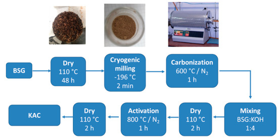
Scheme 1.
Preparation methodology for poly(3,4-ethylenedioxythiophene) (PEDOT)–activated carbon (AC) composite materials.
2.3. Preparation of PEDOT-AC Composite Materials
Preparation of PEDOT:Tosylate composite materials was based on a previous work of ‘in-situ’ polymerization of EDOT using Fe(Tos)3 as an oxidizing agent [40]. A solution of Fe(Tos)3 (20.47 g) and imidazole (2.14 g) in 45 mL of methanol was prepared and added dropwise into a solution of 2.2 mL of EDOT in 55 mL of methanol during 25 min under magnetic stirring at room temperature. After 10 min to homogenize the mixture, a solution of corresponding amount of carbonaceous particles (Table 1) in 10 mL of methanol was pre-dispersed during 5 min at room temperature in an ultrasonic bath (Elma®, Elmasonic S40H, f = 37 kHz, Singer, Germany) and added to the mixture. After 3 h, the temperature was increased to 60 °C and was kept for 2 h. Afterwards, 200 mL of methanol were added to the mixture and kept under stirring at room temperature overnight. Finally, the product was filtered using a nylon 66 membrane (pore size = 0.45 μm) and the process was repeated until the color of the filtered solution become colorless. Scheme 2 summarizes the preparation and characteristics of PEDOT-AC composite materials described in this and the previous section.

Table 1.
Characteristics of PEDOT-AC composite materials prepared.
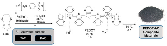
Scheme 2.
Preparation methodology for poly(3,4-ethylenedioxythiophene) (PEDOT)–activated carbon (AC) composite materials.
2.4. Preparation of the Gel Polymer Electrolyte
Preparation of the gel polymer electrolyte was performed according to the literature [41,42]. One gram of H2SO4 was dissolved in 10 g of deionized water. Then, 1 g of PVA was added to the solution and the mixture was kept at 85 °C under magnetic stirring. Stirring continued until the PVA particles were completely dissolved (approximately 1.5 h). After that, the mixture was poured over polytetrafluoroethylene molds of 3 cm diameter. The mixture was kept at room temperature 72 h or until prepared membranes had consistency enough to be manipulated.
2.5. Preparation of Flexible Electrode–Electrolyte Systems
Composite materials were dispersed in diethyl ether (4 mL, 5 mg/mL) with a magnetic stirrer for 24 h before processing. Composite materials were processed by spray-coating the dispersions over the gel polymer electrolyte. Processing was carried over both sides of the electrolyte, by employing 2 mL of the dispersion per side. Scheme 3 represents the preparation of these systems using the electrodes and electrolytes prepared in this work.
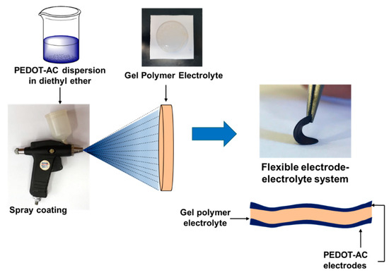
Scheme 3.
Preparation of flexible electrode–electrolyte systems.
2.6. Characterization
Scanning electron microscopy (SEM) micrographs were taken using a Hitachi SU-8000 microscope (Tokyo, Japan). TGA measurements were carried out in a TA Q500 from TA Instruments (New Castle, DE, USA) under nitrogen atmosphere at a heating rate of 10 °C/min up to 800 °C. The sulfur content of materials prepared was obtained using a LECO CHNS-932 Elemental Analyzer (LECO Corporation, St. Joseph, MI, USA). The textural properties of CAC and KAC were characterized by using nitrogen adsorption–desorption isotherms at −196 °C. The measurements were collected with a Micromeritics ASAP 2010 apparatus (Micromeritics, Norcross, GA, USA). Before the analysis, the samples were dried at 200 °C for 6 h under vacuum to remove the adsorbed water. Thus, these samples were transferred into an Ar gas atmosphere glove box after their preparations to prevent the adsorption of water. In a glove box, the sample was added into an analysis cell and the sample weight was calculated from the weight difference of the cell. The cell was sealed with a special cap to prevent the exposure of the sample to the air before the analysis. The surface area measurements were performed according to the Brunauer–Emmett–Teller (BET) method from the nitrogen adsorption points in the range P/P0 = 0.05–0.2. Pore size distribution was determined applying the Barrett–Joyner–Halenda model (BJH) applied to the adsorption branch of the isotherm, assuming cylindrical pore geometry. For each sample, the average pore size was estimated as the diameter corresponding to the maximum of the pore size distribution curve. Total pore volume was taken at a relative pressure P/P0 of 0.985. The as-determined textural properties: BET surface area, pore volume, average pore size and standard deviation for each material by method for three separate measurements, are gathered in Table 2. Raman spectra were obtained using the Renishaw InVia Reflex Raman system (controlled by Renishaw WiRE 3.4 software, Renishaw plc, Wotton-under-Edge, UK). The Raman scattering was excited using an Argon ion laser wavelength of 514.5 nm. The laser beam was focused on the sample with a 0.85 × 100 microscope objective, with a laser power at the sample of approximately 5 mW. The exposure and number of accumulations for the Raman measurements were 10 s and 3 times respectively. X-ray photoelectron spectroscopy (XPS) spectra were recorded using a Fisons MT500 spectrometer (Fison Instruments, East Grinstead, UK) equipped with a hemispherical electron analyzer (CLAM2) and a non-monochromatic Mg Kα X-Ray source operated at 300 W. The samples were fixed on small flat discs supported on an XYZ manipulator placed in the analysis chamber. The residual pressure in this ion-pumped analysis chamber was kept below 10−9 torr during data acquisition. The spectra were collected at a pass energy of 20 eV, which is typical of high-resolution conditions. Spectra were analyzed using CasaXPS software v2.3.15 (Casa Software Ltd., Cheshire, England, UK). The intensities were estimated by calculating the area under each peak after subtraction of the S-shaped background and fitting the experimental curve to a combination of Lorentzian and Gaussian lines of variable proportions. Although specimen charging was observed, it was possible to determine accurate binding energies (BEs) by referencing to the adventitious C1s peak at 285.0 eV. The maximum allowed variation of the binding energy was ±0.2 eV relative to the value specified for peak center. Surface conductivity (σ) of PEDOT:Tosylate and composite materials were obtained using a four-probe setup with a constant current source (CCS-01) and a digital micro-voltmeter (DMV-001) from Scientific Equipment and Services (Roorkee, India). Samples were previously compacted under pressure into pellets of 13 mm of diameter. Ionic conductivity of gel polymer electrolyte was obtained using a Novocontrol GmbH Concept 40 broadband dielectric spectrometer (Montabaur, Germany) in the frequency range between 0.1 and 107 Hz. Samples were placed between two gold-plated flat electrodes applying a voltage of 20 mV. Ionic conductivity was determined in the non-frequency dependent behavior in the graph. Cyclic voltammetry (CV) profiles of electrode–electrolyte systems were recorded using an Autolab PGSTAT30 from Metrohm Autolab B.V. (Utrecht, The Netherlands), samples were placed in a two-electrode cell with a window potential of 1.2 V and a scan rate of 10 mV/s.
Table 2.
Surface area, pore volume and average pore size of commercial activated carbon (CAC) and KAC.
3. Results and Discussion
3.1. PEDOT-AC Composite Materials
Table 1 summarizes the main characteristics of PEDOT-derivative composite materials described in this work. Composite materials were denoted according to the polymer PEDOT:Tosylate (‘PTOS’) followed by the type of AC employed (‘CAC’ or ‘KAC’) and finally with a number that corresponds to the AC weight percentage. Pure polymer PEDOT:Tosylate is included as a reference. The filler/EDOT weight ratio corresponds to the weight ratio between the filler and the EDOT monomer before the polymerization reaction. Filler content affects both the polymerization rate of PEDOT and the final weight percentage of AC in the composite material. Then, the polymer content of composite materials was determined through the sulfur content assessed by elemental analysis [43] and corroborated by the residue weight % obtained by TGA (Table S2). Finally, the particle content in Table 1 was obtained subtracting the resulting polymer content. To confirm the values of particle content determined with this method, physical mixtures of pure PEDOT:Tosylate and both AC employed in this work were prepared by mixing aided by a mortar with the same weight percentages as the ones determined for the ‘in-situ’ composite materials. These latter materials were identified adding ‘PM’ (physical mixture) at the end of each sample acronym. The sulfur content of composite materials and physical mixtures were very similar, which confirms the accuracy of the method employed.
Figure 1 shows the morphological differences between composite materials prepared by ‘in-situ’ polymerization and a composite material prepared by physical mixture. SEM micrographs of powders obtained of PEDOT:Tosylate, CAC, PTOSAC32 and PTOSAC32PM are presented. From SEM micrographs it can be seen the granular morphology of PEDOT:Tosylate particles and the CAC particles with polyhedral shape. These phases can be easily distinguished in the physical mixture in contrast to the ‘in-situ’ composite material.
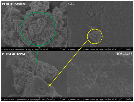
Figure 1.
SEM micrographs of PEDOT:Tosylate, CAC, PTOSAC32 and PTOSAC32PM. Micrographs correspond to 50k× magnification.
Differences between the composite materials based on KAC are presented in Figure 2. SEM micrographs show the porous and heterogeneous structure presented in KAC particles (see also Figure S1). Contrary to CAC composite materials, it is easier to distinguish between the polymer and the KAC phases for both materials. However, it seems that PEDOT particles tend to cover the KAC surface. Determination of the surface area and pore size between the two AC employed in this work are presented in Table 2. From the information presented, the surface area of CAC (2170 m2/g) is much higher than KAC (900 m2/g). This suggests that CAC composite materials should present higher capacitance values from the contribution of electrochemical double layer capacitance. However, pore size is an important factor, as higher pore size increases the electrolyte accessibility to ions [20]. Hence, both KAC and CAC show promising properties heading to energy storage applications.
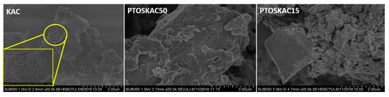
Figure 2.
SEM micrographs of KAC and PEDOT-KAC composite materials. Micrographs correspond to 20k× magnification and the enlargement of the yellow boxed area corresponds to 50k× magnification.
The surface chemical composition of both CAC and KAC were investigated by XPS spectra. The C(1s) and O(1s) XPS spectra can be deconvoluted into diverse components corresponding to carbon atoms in different functional groups (Figure S2 and Table S1). Figure 3a shows a main narrow C(1s) peak (285 eV, C-C sp3) accompanied by a higher binding energy component (286.4 eV, C-OH) and a broader peak (289.5 eV, HO-C=O) indicating the presence of more than one type of carbon [44]. Curve fitting of the O(1s) spectrum yields one peak centered at 532.7 eV, which can be attributed to C-O, and a higher binding energy peak (534.1 eV) due to the presence of a high chemisorbed surface water content of 41.7% (Figure 3b). Similarly, to determine the composition of the as-prepared KAC, Figure 3c shows the peak fitting of the high resolution C(1s) spectrum yielding five components at 284.6 eV (C=C sp2), 285.1 eV (C=C sp3), 286.1 eV (C-OH), 287.1 eV (C=O) and 289 eV (HO-C=O). Curve fitting of the O(1s) spectrum relates the signal to various surface oxygenated carbon groups. The low binding energy peak (531.4 eV) is assigned to C=O and the other two peaks match the proposed assignation mentioned above for CAC, 532.7 eV (C-O) and 534 eV (water; Figure 3d). From results shown by the XPS spectra for both AC, it is worthy to mention the successful surface activation of KAC appearing various new surface unsaturated or oxygenated carbon groups compared with CAC [33,45].
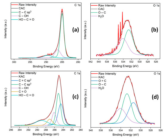
Figure 3.
C(1s) and O(1s) XPS spectra of CAC (a,b) and KAC (c,d).
The chemical composition of the PEDOT-based composites was also characterized by XPS spectra. Typical carbon spectra (C1s) of PEDOT, including the aromatic C=C of PEDOT at 284.5 eV, the C-O/C-S bonds at 286.7 eV, and the C=O/C=S bonds at 288.7 eV, are demonstrated in Figure S2 [46,47]. The presence of the C=C bond peak (284 eV) is an obvious demonstration of the presence of PEDOT on the surface of CAC-derived composites. Generally, for all PEDOT-derived composites prepared in this work, the presence of the lower binding energy peaks at 164 and 163 eV, spin-split doublets of sulfur atoms in PEDOT backbone, confirms the existence of PEDOT-Tosylate [48].
Thermal stability of PEDOT-AC composite materials was evaluated by TGA as it is presented in Figure 4 (see Figure S3 and Table S2 for further information). Values of T5 and T50 demonstrate the improved thermal stability of composite materials respect to PEDOT:Tosylate. Moreover, the residue obtained at 800 °C has a good correspondence with the CAC content determined by elemental analysis in Table 1, which confirms again the particle content present in the materials prepared.
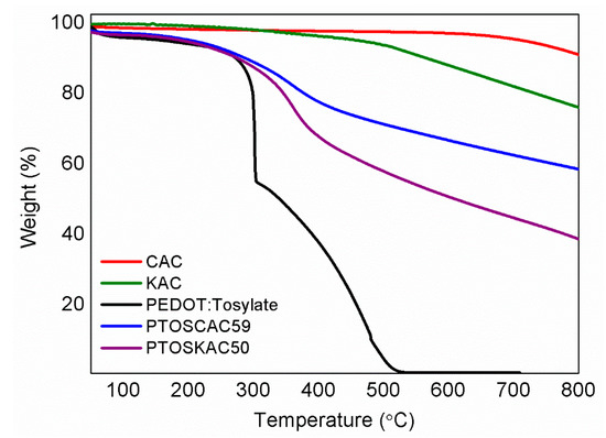
Figure 4.
TGA curves (a)of CAC (red), KAC (olive); PEDOT:Tosylate (black); PTOSCAC59 (blue) and PTOSKAC50 (purple).
Dependence of σ values with respect to the AC content is presented in Table 1 and Figure S4. The value of σ decreased when AC content increased. Unfortunately, raw CAC and composite materials with high CAC loading could not be measured because pellets were highly brittle and unable to compress. However, it is known that AC conductivity values ranged between 0.1 and 1 S/cm, thus CAC and KAC σ values were in this value range, which are lower comparing with synthesized PEDOT:Tosylate [8]. From Figure S4 and Table 1 it is observed that σ decreased more than half when particle content was between 5 and 15 wt %. This decrease in σ continued when particle content increased and it seemed that other factors such as the type of AC used, surface area or homogeneity of the material had lower influence on σ values.
The Raman spectra of materials prepared are represented in Figure 5. The Raman spectra show the bands associated to PEDOT and the two AC employed in this work. The bands presented in 1348 cm−1 and 1600 cm−1 correspond to the band D and G respectively associated to AC [49]. The graphitization degree, defined as the ratio of the intensities between the G and D band (IG/ID) was calculated for both AC (Figure S5). Values obtained indicate a higher degree of disorder in CAC. Characteristics PEDOT-Tosylate bands were found in 1436, 1506 and 1555 cm−1, which are present in the spectra of composite materials [50]. The heterogeneity of PTOSAC32PM is confirmed in Figure S5, where different measurements were performed in four regions of the sample. The difference in peak intensities of PEDOT and CAC confirmed the heterogeneity of the samples, in contrast to the composite material.
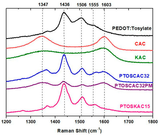
Figure 5.
Raman spectra of PEDOT-activated carbon composite materials spectra of PEDOT:Tosylate (black), CAC (red), KAC (green), PTOSAC32 (blue), PTOSAC32PM (purple) and PTOSKAC15 (violet).
3.2. Electrode–Electrolyte Systems
The ionic stability of the gel polymer electrolyte was determined by measuring the ionic conductivity versus time of the electrolyte presented in Figure 6. The first ionic conductivity measurement of the electrolyte was obtained when the material had enough consistency for handling. Ionic conductivity shows and considerable decrease during the first ten days. It is important to note that the relative error of measurements was determined considering differences of thickness of the sample before and after the ionic conductivity measurement. Those thickness differences do not occur or are negligible after day 8, which are attributed to the gel formation and evaporation of residual water. From the eighth day onwards, ionic conductivity values remains relatively constant (≈20 mS/cm) until a period of 55 days demonstrating the stability of this electrolyte. It is important to highlight that despite in the literature some PVA electrolyte systems are widely used in supercapacitors applications [51], to our knowledge, very little details are found in literature about the ionic conductivity and stability of these materials with respect to time.
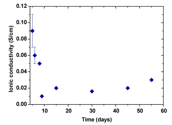
Figure 6.
Ionic conductivity evolution of the gel polymer electrolyte over time.
CV curves of most interesting samples are represented in Figure 7a. It is worth mentioning that all electrode–electrolyte systems were prepared until the electrolyte had enough consistency to be manipulated and presented a stable ionic conductivity, which is after approximately 15 days. As it is presented in Scheme 2, diethyl ether was used to disperse the composite materials and spray over the electrolyte. Other solvents like ethanol or methanol were tested, however, the election of diethyl ether was due to three reasons: (1) easy dispersion of the electrode; (2) fast volatilization of the solvent hindering phase separation and (3) non-visible interaction with the electrolyte. The curves obtained shows the rectangular shape produced from EDLC capacitance but also the non-ideal behavior accused of a faradaic pseudocapacitance. Capacitance per surface area (Csup) was calculated from the CV curves and results obtained are presented in Table 3. Csup and σ values were correlated in Figure 7b. Despite that pure PEDOT:Tosylate had the highest conductivity, this property did not have a direct effect on the electrochemical performance as shown in the CV curves. The addition of AC in the polymer matrix improved the capacitance values with respect to the pure polymer, due probably to the higher surface area, which is beneficial for the ion diffusion through the electrolyte. Comparing the Csup values of PTOSCAC32 and PTOSCAC32PM, an increment of Csup of the composite material in comparison to a physical mixture was observed. Moreover, the concomitant increase of capacitance with the CAC content up 50 wt % was demonstrated as shown by PTOSCAC50 [19].
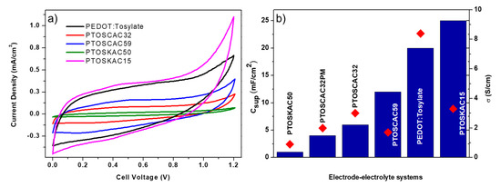
Figure 7.
CV curves of electrode–electrolyte systems prepared (a) and Csup values of electrode–electrolyte systems (blue bars). σ values of composite material used as electrodes (b).
Table 3.
Characteristics of electrode–electrolyte systems prepared.
Nevertheless, the case of KAC did not follow the same behavior as CAC. PTOSKAC50 shows a poor electrochemical performance with a Csup value even lower than raw PEDOT:Tosylate. This effect can be explained to the porosity, which is mainly macroporous in KAC, and to the lower surface area compared to CAC. The high percentage of KAC in this sample shows large PEDOT-free zones making the surface area and pore size the ones that directly drives the electrochemical properties of this composite material.
However, PTOSKAC15 shows the highest Csup despite the lower surface area of KAC and the lower conductivity. The explanation of this performance is not easy to discuss. However, there is evidence, which leads us to think that KAC in moderate concentrations may act as a scaffold for PEDOT-Tosylate polymerization inside the pores [52]. When PEDOT is distributed into the AC pores a hybridization occurs due to the high energy densities of the redox-active materials, giving PEDOT a high surface-to-volume ratio, which improves both the energy and power density and limiting the distance for ion diffusion inside PEDOT [53]. The formation of nano-structured PEDOT into AC pores and surface (Figure 2) results to a suitable surface morphology for the fabrication of the electrodes. The value of capacitance is higher compared with the CAC electrode and to the single PEDOT electrode. This surface morphology in PTOSKAC15 could be different from that observed for the composite materials prepared with CAC due to its differences in pore size, specific surface and the presence of PEDOT (not only coating the KAC surface, but also inside the pores), not being observed the hybrid behavior shown by PTOSKAC15. Some authors have also attributed this behavior to the combined effect of double layer and redox capacitance [19].
To corroborate this behavior, C(1s), O(1s) and S(2p) XPS high resolution spectra are shown in Figure 8, with further details of signals in Table 4. As shown, the C=C and C-O content in KAC15 increased after redox polymerization of PEDOT. Meanwhile, C(1s) KAC peaks at between 286 and 289 eV, which were typically assigned to epoxide, hydroxyl, carboxyl and acid groups (Figure 3) were significantly weakened or completely vanished. This fact revealed that most of these groups also reacted during redox polymerization plentiful hybridizing the surface and pores of KAC with PEDOT as revealed the also remarkable increase of O-C (532 eV, 65.6% area) and also the decrease of S-O (166.2 eV, 17.2% area) in O(1s) and S(2p) spectra, respectively. This observation could confirm the unusual Csup value obtained by CV by assuming the formation of small PEDOT particles, homogeneously covering the entire surface and pores in PTOSKAC15, obtaining a material with a new hybrid behavior compared to the rest of composite materials. This hybrid composite material has strong π–π interaction between PEDOT chains and KAC, as well as a good compatibility between the C=C and oxygenated surface groups on KAC and PEDOT-Tosylate chains. This π–π strong interactions cause the red shift of C=C, C-S, S-S and S-O bonds [54] in PTOSKAC15 material demonstrating the synergistic effect of KAC and PEDOT (Figure 8).
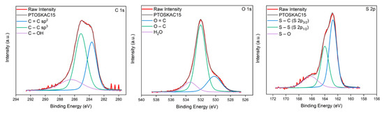
Figure 8.
C(1s), O(1s) and S(2p) XPS spectra of PTOSKAC15.
Table 4.
Subdivision of carbon, oxygen and sulfur signals for PTOSKAC15.
4. Conclusions
PEDOT-AC composite materials were prepared by performing ‘in-situ’ polymerization of EDOT in the presence of AC particles. Two types of AC were used, commercial CAC and KAC where the latter was successfully prepared from biowaste residues of the beer industry. Properties of both AC employed such as the surface area, pore size and AC content had an effect on the properties of the composite material. The value of σ of composite materials decreased when AC content increased. This is independent of the AC used, particle morphology and homogeneity of these materials.
A fast and scalable methodology, which consisted of spraying dispersions of composite materials employed as electrodes over a gel polymer electrolyte, was carried out in order to obtain flexible electrode–electrolyte systems.
Despite that σ values of composite materials were lower compared with the raw polymer, some composite materials exhibited promising properties heading to supercapacitors applications. Particularly PTOSKAC15 showed an improved electrochemical higher than pure PEDOT:Tosylate, obtaining a Csup value of 25 mF/cm2. This performance is explained due to the formation of a hybrid material where KAC acts as a scaffold for EDOT polymerization inside the pores. Electrochemical behavior of that material is promising, and an extended electrochemical characterization is needed to confirm the feasibility of these hybrid composite materials in a real device.
Supplementary Materials
The following are available online at https://www.mdpi.com/2504-477X/4/3/87/s1, Figure S1: SEM images of (a) CAC and (b) KAC; Table S1: C(1s), O(1s) and S(2p) XPS spectra of overall composite materials prepared in this work; Figure S2: C(1s), O(1s) and S(2p) XPS spectra of composite materials; Figure S3: TGA of PEDOT:Tosylate, CAC, KAC and all prepared composite materials; Table S2: T5, T50 and % residue of materials presented in Figure S2; Figure S4: Dependence of σ respect to the AC content; Figure S5: Raman spectra of PTOSCACPM obtained in different regions of the sample.
Author Contributions
Conceptualization, F.J.G. and M.H.; methodology, F.J.G., A.M. and M.H.; validation, F.J.G. and M.H.; formal analysis, F.J.G. and M.H.; investigation, F.J.G., A.M. and M.H.; resources, M.H. and R.V.; data curation, J.A.-M., M.H. and R.V.; writing—original draft preparation, F.J.G. and M.H.; writing—review and editing, F.J.G., M.H. and R.V.; visualization, J.A.-M., F.J.G., A.M. and M.H.; supervision, M.H. and R.V.; project administration, F.J.G. and M.H. and R.V.; funding acquisition, M.H. and R.V. All authors have read and agreed to the published version of the manuscript.
Funding
Francisco González and Mario Hoyos are grateful to CONACYT-SENER for the scholarship granted (CVU559770/Registro 297710).
Acknowledgments
Juan Cereijo from Cerveza MICA is gratefully acknowledged for Brewer’s Spent Grain provision. Irene Llorente from Surface Characterization Laboratory of the National Centre for Metallurgical Research (CENIM-CSIC) is acknowledged for XPS spectra analysis.
Conflicts of Interest
The authors declare no conflict of interest.
References
- Li, L.; Wu, Z.; Yuan, S.; Zhang, X.B. Advances and challenges for flexible energy storage and conversion devices and systems. Energy Environ. Sci. 2014, 7, 2101–2122. [Google Scholar] [CrossRef]
- Gür, T.M. Review of electrical energy storage technologies, materials and systems: Challenges and prospects for large-scale grid storage. Energy Environ. Sci. 2018, 11, 2696–2767. [Google Scholar] [CrossRef]
- Yang, Z.; Zhang, J.; Kintner-Meyer, M.C.W.; Lu, X.; Choi, D.; Lemmon, J.P.; Liu, J. Electrochemical energy storage for green grid. Chem. Rev. 2011, 111, 3577–3613. [Google Scholar] [CrossRef] [PubMed]
- Goodenough, J.B.; Kim, Y. Challenges for rechargeable batteries. J. Power Sour. 2011, 196, 6688–6694. [Google Scholar] [CrossRef]
- Lin, Z.; Goikolea, E.; Balducci, A.; Naoi, K.; Taberna, P.L.; Salanne, M.; Yushin, G.; Simon, P. Materials for supercapacitors: When Li-ion battery power is not enough. Mater. Today 2018, 21, 419–436. [Google Scholar] [CrossRef]
- Meng, Q.; Cai, K.; Chen, Y.; Chen, L. Research progress on conducting polymer based supercapacitor electrode materials. Nano Energy 2017, 36, 268–285. [Google Scholar] [CrossRef]
- Snook, G.A.; Kao, P.; Best, A.S. Conducting-polymer-based supercapacitor devices and electrodes. J. Power Sources 2011, 196, 1–12. [Google Scholar] [CrossRef]
- Zhang, L.L.; Zhou, R.; Zhao, X.S. Graphene-based materials as supercapacitor electrodes. J. Mater. Chem. 2010, 20, 5983–5992. [Google Scholar] [CrossRef]
- Salinas-Torres, D.; Ruiz-Rosas, R.; Morallón, E.; Cazorla-Amorós, D. Strategies to enhance the performance of electrochemical capacitors based on carbon materials. Front. Mater. 2019, 6, 1–24. [Google Scholar] [CrossRef]
- Liu, Y.; Weng, B.; Razal, J.M.; Xu, Q.; Zhao, C.; Hou, Y.; Seyedin, S.; Jalili, R.; Wallace, G.G.; Chen, J. High-performance flexible all-solid-state supercapacitor from large free-standing graphene-PEDOT/PSS Films. Sci. Rep. 2015, 5, 1–11. [Google Scholar] [CrossRef]
- Pang, H.; Xu, L.; Yan, D.X.; Li, Z.M. Conductive polymer composites with segregated structures. Prog. Polym. Sci. 2014, 39, 1908–1933. [Google Scholar] [CrossRef]
- Deng, H.; Lin, L.; Ji, M.; Zhang, S.; Yang, M.; Fu, Q. Progress on the morphological control of conductive network in conductive polymer composites and the use as electroactive multifunctional materials. Prog. Polym. Sci. 2014, 39, 627–655. [Google Scholar] [CrossRef]
- Alvi, F.; Ram, M.K.; Basnayaka, P.A.; Stefanakos, E.; Goswami, Y.; Kumar, A. Graphene-polyethylenedioxythiophene conducting polymer nanocomposite based supercapacitor. Electrochim. Acta 2011, 56, 9406–9412. [Google Scholar] [CrossRef]
- Lota, K.; Khomenko, V.; Frackowiak, E. Capacitance properties of poly(3,4-ethylenedioxythiophene)/carbon nanotubes composites. J. Phys. Chem. Solids 2004, 65, 295–301. [Google Scholar] [CrossRef]
- Murugan, A.V.; Viswanath, A.K.; Campet, G.; Gopinath, C.S.; Vijayamohanan, K. Enhancement of double-layer capacitance behavior and its electrical conductivity in layered poly (3, 4-ethylenedioxythiophene)-based nanocomposites. Appl. Phys. Lett. 2005, 87, 1–3. [Google Scholar] [CrossRef]
- Sharma, R.K.; Zhai, L. Multiwall carbon nanotube supported poly(3,4-ethylenedioxythiophene)/manganese oxide nano-composite electrode for super-capacitors. Electrochim. Acta 2009, 54, 7148–7155. [Google Scholar] [CrossRef]
- Xu, Y.; Wang, Y.; Liang, J.; Huang, Y.; Ma, Y.; Wan, X.; Chen, Y. A hybrid material of graphene and poly (3,4-ethyldioxythiophene) with high conductivity, flexibility, and transparency. Nano Res. 2009, 2, 343–348. [Google Scholar] [CrossRef]
- Khasim, S.; Pasha, A.; Badi, N.; Lakshmi, M.; Mishra, Y.K. High performance flexible supercapacitors based on secondary doped PEDOT-PSS-graphene nanocomposite films for large area solid state devices. RSC Adv. 2020, 10, 10526–10539. [Google Scholar] [CrossRef]
- Selvakumar, M.; Bhat, D.K. Activated carbon-polyethylenedioxythiophene composite electrodes for symmetrical supercapacitors. J. Appl. Polym. Sci. 2008, 107, 2165–2170. [Google Scholar] [CrossRef]
- Vaquero, S.; Díaz, R.; Anderson, M.; Palma, J.; Marcilla, R. Insights into the influence of pore size distribution and surface functionalities in the behaviour of carbon supercapacitors. Electrochim. Acta 2012, 86, 241–247. [Google Scholar] [CrossRef]
- Hwang, J.Y.; Li, M.; El-Kady, M.F.; Kaner, R.B. Next-generation activated carbon supercapacitors: A simple step in electrode processing leads to remarkable gains in energy density. Adv. Funct. Mater. 2017, 27, 1605745. [Google Scholar] [CrossRef]
- Ioannidou, O.; Zabaniotou, A. Agricultural residues as precursors for activated carbon production-A review. Renew. Sustain. Energy Rev. 2007, 11, 1966–2005. [Google Scholar] [CrossRef]
- Balathanigaimani, M.S.; Shim, W.G.; Kim, C.; Lee, J.W.; Moon, H. Surface structural characterization of highly porous activated carbon prepared from corn grain. Surf. Interface Anal. 2009, 41, 484–488. [Google Scholar] [CrossRef]
- Ramirez-Castro, C.; Schütter, C.; Passerini, S.; Balducci, A. Microporous carbonaceous materials prepared from biowaste for supercapacitor application. Electrochim. Acta 2016, 206, 452–457. [Google Scholar] [CrossRef]
- Klose, M.; Reinhold, R.; Logsch, F.; Wolke, F.; Linnemann, J.; Stoeck, U.; Oswald, S.; Uhlemann, M.; Balach, J.; Markowski, J. Softwood lignin as a sustainable feedstock for porous carbons as active material for supercapacitors using an ionic liquid electrolyte. ACS Sustain. Chem. Eng. 2017, 5, 4094–4102. [Google Scholar] [CrossRef]
- Wu, F.C.; Tseng, R.L.; Hu, C.C.; Wang, C.C. Physical and electrochemical characterization of activated carbons prepared from firwoods for supercapacitors. J. Power Sources 2004, 138, 351–359. [Google Scholar] [CrossRef]
- Arvind, D.; Hegde, G. Activated carbon nanospheres derived from bio-waste materials for supercapacitor applications—A review. RSC Adv. 2015, 5, 88339–88352. [Google Scholar] [CrossRef]
- Mensah-Darkwa, K.; Zequine, C.; Kahol, P.K.; Gupta, R.K. Supercapacitor energy storage device using biowastes: A sustainable approach to green energy. Sustainability 2019, 11, 414. [Google Scholar] [CrossRef]
- Sun, Y.; Xue, J.; Dong, S.; Zhang, Y.; An, Y.; Ding, B.; Zhang, T.; Dou, H.; Zhang, X. Biomass-derived porous carbon electrodes for high-performance supercapacitors. J. Mater. Sci. 2020, 55, 5166–5176. [Google Scholar] [CrossRef]
- Mussatto, S.I.; Fernandes, M.; Rocha, G.J.M.; Órfão, J.J.M.; Teixeira, J.A.; Roberto, I.C. Production, characterization and application of activated carbon from Brewer’s spent grain lignin. Bioresour. Technol. 2010, 101, 2450–2457. [Google Scholar] [CrossRef]
- Vanreppelen, K.; Vanderheyden, S.; Kuppens, T.; Schreurs, S.; Yperman, J.; Carleer, R. Activated carbon from pyrolysis of brewer’s spent grain: Production and adsorption properties. Waste Manag. Res. 2014, 32, 634–645. [Google Scholar] [CrossRef]
- Wakizaka, H.; Miyake, H.; Kawahara, Y. Utilization of beer lees waste for the production of activated carbons: The influence of protein fractions on the activation reaction and surface properties. Sustain. Mater. Technol. 2016, 8, 1–4. [Google Scholar] [CrossRef]
- Lee, S.G.; Park, K.H.; Shim, W.G.; Balathanigaimani, M.S.; Moon, H. Performance of electrochemical double layer capacitors using highly porous activated carbons prepared from beer lees. J. Ind. Eng. Chem. 2011, 17, 450–454. [Google Scholar] [CrossRef]
- Lu, X.; Yu, M.; Wang, G.; Tong, Y.; Li, Y. Flexible solid-state supercapacitors: Design, fabrication and applications. Energy Environ. Sci. 2014, 7, 2160–2181. [Google Scholar] [CrossRef]
- Muralee Gopi, C.V.V.; Vinodh, R.; Sambasivam, S.; Obaidat, I.M.; Kim, H.-J. Recent progress of advanced energy storage materials for flexible and wearable supercapacitor: From design and development to applications. J. Energy Storage 2020, 27, 101035. [Google Scholar] [CrossRef]
- Xue, Q.; Sun, J.; Huang, Y.; Zhu, M.; Pei, Z.; Li, H.; Wang, Y.; Li, N.; Zhang, H.; Zhi, C. Recent progress on flexible and wearable supercapacitors. Small 2017, 13, 1–11. [Google Scholar] [CrossRef]
- Zhang, Q.; Sun, J.; Pan, Z.; Zhang, J.; Zhao, J.; Wang, X.; Zhang, C.; Yao, Y.; Lu, W.; Li, Q.; et al. Stretchable fiber-shaped asymmetric supercapacitors with ultrahigh energy density. Nano Energy 2017, 39, 219–228. [Google Scholar] [CrossRef]
- Hsiao, C.; Lee, C.; Tai, N. Biomass-derived three-dimensional carbon framework for a flexible fibrous supercapacitor and its application as a wearable smart textile. RSC Adv. 2020, 10, 6960–6972. [Google Scholar] [CrossRef]
- Zequine, C.; Ranaweera, C.K.; Wang, Z.; Dvornic, P.R.; Kahol, P.K.; Singh, S.; Tripathi, P.; Srivastava, O.N.; Singh, S.; Gupta, B.K. High-performance flexible supercapacitors obtained via recycled jute: Bio-waste to energy storage approach. Sci. Rep. 2017, 7, 1–12. [Google Scholar] [CrossRef]
- González, F.; Tiemblo, P.; Hoyos, M. ‘In-situ’ approaches for the preparation of polythiophene-derivative cellulose composites with high flexibility and conductivity. Appl. Sci. 2019, 9, 3371. [Google Scholar] [CrossRef]
- Meng, C.; Liu, C.; Chen, L.; Hu, C.; Fan, S. Highly flexible and all-solid-state paperlike polymer supercapacitors. Nano Lett. 2010, 10, 4025–4031. [Google Scholar] [CrossRef] [PubMed]
- Anothumakkool, B.; Soni, R.; Bhange, S.N.; Kurungot, S. Novel scalable synthesis of highly conducting and robust PEDOT paper for a high performance flexible solid supercapacitor. Energy Environ. Sci. 2015, 8, 1339–1347. [Google Scholar] [CrossRef]
- Lee, S.B.; Lee, S.M.; Park, N.I.; Lee, S.; Chung, D.W. Preparation and characterization of conducting polymer nanocomposite with partially reduced graphene oxide. Synth. Met. 2015, 201, 61–66. [Google Scholar] [CrossRef]
- Lennon, D.; Lundie, D.T.; Jackson, S.D.; Kelly, G.J.; Parker, S.F. Characterization of activated carbon using X-ray photoelectron spectroscopy and inelastic neutron scattering spectroscopy. Langmuir 2002, 18, 4667–4673. [Google Scholar] [CrossRef]
- Hsieh, C.-T.; Teng, H. Influence of oxygen treatment on electric double-layer capacitance of activated carbon fabrics. Carbon 2002, 40, 667–674. [Google Scholar] [CrossRef]
- Guo, X.; Jian, J.; Lin, L.; Zhu, H.; Zhu, S. O2 plasma-functionalized SWCNTs and PEDOT/PSS composite film assembled by dielectrophoresis for ultrasensitive trimethylamine gas sensor. Analyst 2013, 138, 5265–5273. [Google Scholar] [CrossRef]
- Si, W.; Lei, W.; Han, Z.; Zhang, Y.; Hao, Q.; Xia, M. Electrochemical sensing of acetaminophen based on poly (3,4-ethylenedioxythiophene)/graphene oxide composites. Sens. Actuators B Chem. 2014, 193, 823–829. [Google Scholar] [CrossRef]
- Tung, T.T.; Kim, T.Y.; Shim, J.P.; Yang, W.S.; Kim, H.; Suh, K.S. Poly(ionic liquid)-stabilized graphene sheets and their hybrid with poly(3,4-ethylenedioxythiophene). Org. Electron. 2011, 12, 2215–2224. [Google Scholar] [CrossRef]
- Shimodaira, N.; Masui, A. Raman spectroscopic investigations of activated carbon materials. J. Appl. Phys. 2002, 92, 902–909. [Google Scholar] [CrossRef]
- Garreau, S.; Louarn, G.; Buisson, J.P.; Froyer, G.; Lefrant, S. In situ spectroelectrochemical Raman studies of poly(3,4-ethylenedioxythiophene) (PEDT). Macromolecules 1999, 32, 6807–6812. [Google Scholar] [CrossRef]
- Alipoori, S.; Mazinani, S.; Aboutalebi, S.H.; Sharif, F. Review of PVA-based gel polymer electrolytes in flexible solid-state supercapacitors: Opportunities and challenges. J. Energy Storage 2020, 27, 101072. [Google Scholar] [CrossRef]
- Itoi, H.; Maki, S.; Ninomiya, T.; Hasegawa, H.; Matsufusa, H.; Hayashi, S.; Iwata, H.; Ohzawa, Y. Electrochemical polymerization of pyrene and aniline exclusively inside the pores of activated carbon for high-performance asymmetric electrochemical capacitors. Nanoscale 2018, 10, 9760–9772. [Google Scholar] [CrossRef] [PubMed]
- Lei, C.; Wilson, P.; Lekakou, C. Effect of poly(3,4-ethylenedioxythiophene) (PEDOT) in carbon-based composite electrodes for electrochemical supercapacitors. J. Power Sources 2011, 196, 7823–7827. [Google Scholar] [CrossRef]
- Du, F.-P.; Cao, N.-N.; Zhang, Y.-F.; Fu, P.; Wu, Y.G.; Lin, Z.-D.; Shi, R.; Amini, A.; Cheng, C. PEDOT:PSS/graphene quantum dots films with enhanced thermoelectric properties via strong interfacial interaction and phase separation. Sci. Rep. 2018, 8, 6441. [Google Scholar] [CrossRef] [PubMed]


© 2020 by the authors. Licensee MDPI, Basel, Switzerland. This article is an open access article distributed under the terms and conditions of the Creative Commons Attribution (CC BY) license (http://creativecommons.org/licenses/by/4.0/).