Article

Performance of Composite Metal Foam Armors against Various Threat Sizes

1
Advanced Materials Research Lab, Department of Mechanical and Aerospace Engineering, North Carolina State University, Raleigh, NC 27695, USA
2
Aviation Development Directorate (ADD), U.S. Army Combat Capabilities Development Command, Aviation & Missile Center, Fort Eustis, VA 23604, USA
*
Author to whom correspondence should be addressed.
J. Compos. Sci. 2020, 4(4), 176; https://doi.org/10.3390/jcs4040176
Submission received: 7 September 2020 / Revised: 10 November 2020 / Accepted: 13 November 2020 / Published: 23 November 2020
(This article belongs to the Special Issue Feature Papers in Journal of Composites Science in 2020)

Abstract

:
The ballistic capabilities of composite metal foam (CMF) armors were experimentally tested against a 14.5 × 114 mm B32 armor-piercing incendiary (API) and compared to various sizes of armor-piercing (AP) ballistic threats, ranging from a 7.62 to 12.7 mm. Three different arrangements of layered hard armors were designed and manufactured using ceramic faceplates (in one layer, two layers or multiple tiles), a combination of ceramic and steel face sheets, with a single-layered CMF core, and a thin aluminum backing. The performance of various CMF armor designs against the 14.5 mm rounds are compared to each other and to the performance of the rolled homogeneous armor standard to identify the most efficient design for further investigations. The percentage of kinetic energy absorbed by the CMF layer in various armor arrangements and in tests against various threat sizes was calculated and compared. It appears that the larger the threat size, the more efficient the CMF layer will be due to a greater number of hollow metal spheres that are engaged in absorbing the impact energy. The results from this study will help to model and predict the performance of CMF armors against various threat sizes and impact energies.

1. Introduction

Ongoing conflicts around the world require advanced armors to protect military and law enforcement against new and existing ballistic rounds. The next generation of armors must be lightweight and perform reliably against a variety of threats [1]. Historically, personnel armors are made up of fiber composites paired with ceramic faceplates [1,2,3]. Alternatively, armors for land and air vehicles must perform against an extensive array of threats that include a variety of ballistic rounds, blast, and fragment impacts. For this reason, military vehicles are generally constructed using bulk heavy metals such as rolled homogeneous armor (RHA) [4]. Metal armors are relatively heavy and must be improved upon in order to reduce the overall weight of these vehicles. A reduction in weight will improve a vehicle’s fuel efficiency, its overall maneuverability and stealth. The lighter vehicles can allow for longer missions without the need for additional protection for troops during refueling [1].
There have been slight improvements to RHA’s effectiveness against armor-piercing (AP) cores that includes the development of high hardness armors (HHAs) [5], and ultra-high hardness armors (UHA) [6]. A potential alternative to the bulk and heavy metal armors are layered hard armors [7,8,9,10,11,12,13,14]. Layered hard armors are made by pairing a ceramic faceplate with a composite or metal backing and offer a similar performance to the steel armors with a better mass efficiency. These armors use a ceramic faceplate due to its relatively lightweight and high hardness. The ceramic erodes the hardened steel core of the AP projectile and allows the backing plate to absorb the residual energy of the core. This pairing has been effectively used with SiC [7], B4C [8], and alumina ceramics [9,10]. Layered hard armors for vehicle applications have been tested using bulk metals such as aluminum [11], steel [12], and titanium [13]. Other alternatives include the use of ultra-high molecular weight polyethylene (UHMWPE) and other composite materials such as spall liners on the back of standard bulk metal armors for testing against AP threats [14]. In addition to layered armors, geometric layups have also been tested against larger caliber rounds in order to redirect and trap the core of the projectile [14,15]. This category also includes armors that use an air gap between layers in order to redirect and tumble the core [14,15]. Geometric armors have the potential for improved protection but require larger thicknesses and complex arrangements to ensure complete tipping and disruption of the round when attached to the exterior of a vehicle. The current field of vehicle armors can be further improved by using novel materials with unique energy absorption capabilities, such as composite metal foams.
Lightweight high-performance composite metal foam (CMF) has been proven to absorb the ballistic impact of various sized threats [16,17]. Composite metal foam is a closed-cell metal foam manufactured by surrounding hollow metal spheres with a metallic matrix. CMF can be made out of many different metals, alloys, and combinations, such as. aluminum, steel, titanium, etc. For example, it can be made 100% out of steel, but, due to its porosities, it weighs as little as aluminum. Steel–steel composite metal foam (SS-CMF) is manufactured by surrounding hollow steel spheres with a steel matrix using the powder metallurgy technique, while aluminum–steel composite metal foam (Al-S CMF) is manufactured by surrounding the hollow steel spheres by an aluminum matrix using casting. CMF is known for its extraordinary energy absorption capability at a relatively low density compared to bulk metal alternatives [16,17,18,19,20,21,22,23,24,25,26]. CMF can compress to relatively high strains at a constant stress (plateau stress). During the plateau region, the porosities collapse and absorb impact energy under compression. Once all the porosities within the foam are collapsed, the material begins to act more like its parent metal.
CMF has a very high plateau strength under compression when compared to other metal foams [23,27], as can be seen in the stress–strain curve in Figure 1 [18,28,29,30,31,32]. Other metal foams, such as syntactic foam can be compared to CMF for their overall structure and properties. Syntactic foams are a separate class of foam materials that are manufactured by surrounding hollow ceramic spheres with a polymer or metallic matrix [33,34,35,36]. In the most recent studies, metal matrix syntactic foams have primarily been manufactured using an aluminum matrix surrounding hollow ceramic spheres [37,38,39]. By definition, these foams are intrinsically different in their material and structure compared to CMF which uses metal for both the hollow spheres and the surrounding matrix. Szlancsik et al. have completed testing of a metal foam, which should be considered a composite metal foam, using iron hollow spheres surrounded by an aluminum matrix. This testing is most similar to Al-S and SS-CMF and can be used for comparison to aluminum and stainless steel CMF [32]. It can be seen that both the Al-S CMF and SS-CMF have a higher yield and plateau stress than the Al-Fe foam. In addition, the Al-S CMF and SS-CMF have an energy absorption of 58 [40] and 68 MJ/m3 [26,31] respectively, while the Al-Fe foam absorbs 36 MJ/m3 [32]. The SS-CMF is more ductile with a higher densification strain, plateau strength, energy absorption, and shows uniform deformation thus making it preferable for armor applications. The cushioning behavior of CMF allows the armor to locally compress under the bullet, reducing the backplate signature (indentation depth) and the amount of energy transferred through the armor [16]. CMF has also been found to have increased strength under high-speed impacts [16,20,21]. Such a strengthening effect of the material makes CMF suitable for armor applications. In conjunction with a ceramic faceplate and a thin supporting backplate, CMF can effectively absorb the energy of a variety of ballistic threats [16,17]. CMF armors have previously been tested against 7.62 mm ball and AP (also known as the 0.30 caliber) [16] as well as 12.7 mm ball and AP (also known as the 0.50 caliber) [17] rounds. This work is split into two sections: the first section covers the results of CMF hard armors against the 14.5 × 114 mm B32 armor-piercing incendiary (API) round (a much larger threat than the previous rounds with a very high dynamic energy). Three different armor arrangements, each using a different face sheet, were tested in order to determine the one most effective for defeating the large incendiary threat. The second section compares the results against the B32 API to the performance of CMF armors against smaller AP threats (the 7.62 and 12.7 mm M2 AP).

2. Materials and Methods

2.1. Materials and Manufacturing

The SS-CMF panels were manufactured using powder metallurgy sintering of hollow spheres made of stainless steel and manufactured by Hollomet GmbH located in Dresden, Germany and designed with an outer diameter of 2 mm and a wall thickness of 100 µm. The spheres are surrounded with a 316 L stainless steel powder from North American Höganas. The molds were vibrated to promote movement of the powder to fill the open volume between the spheres. The spheres become arranged in a random, loosely packed structure with a fill percentage of approximately 59% [26]. The mold was heated within a vacuum hot press to the sintering temperature of the metallic matrix and allowed to passively cool under high vacuum. Further details on the chemical composition and manufacturing of SS-CMF using the powder metallurgy technique can be found in previous publications [26,41]. The CMF panels were manufactured in 25 × 25 cm and 30 × 30 cm sizes with a density between 2.8 and 3 g/cm3. A digital image of the SS-CMF cross section when cut is shown in Figure 2a. In addition, SEM images of the SS-CMF after manufacturing are shown in Figure 2b,c, revealing the porosities created by the hollow metal spheres and the surrounding matrix between them.
The CMF panels were layered between a ceramic face made of boron carbide (B4C) and an aluminum 7075-T6 backplate. The boron carbide (B4C) ceramic tiles were purchased in two sizes from two separate companies, Saint-Gobain and M Cubed Technologies, II-VI Inc. (Saxonburg, PA, USA). The ceramics are both reaction-bonded B4C tiles, which were chosen for their relatively high hardness and lower density compared to other ceramics, such as alumina-based ceramics [8]. The aluminum 7075-T6 has one of the highest tensile strengths of the aluminum alloys and has been previously investigated for use in ballistic armors [42,43]. The aluminum backing is used in the layered armor to support the CMF core under tension. Two of the armor arrangements also used an RHA faceplate above the ceramic layer for testing against the 14.5 mm API. RHA is a well-known conventional steel armor that has been used to establish military standards [4]. The RHA layer is used to stabilize the ceramic and gives the layered armor a durable exterior layer for vehicle application.
The layered armors are assembled using a vacuum bagging technique with a thin layer of high-strength epoxy between each component. The epoxy used to adhere the layers was a two-part Loctite EA 9309NA aerospace grade epoxy with a high tensile and peel strength. Three armors, each with a different arrangement, were tested against the 14.5 mm B32 API round. Armor 1 was manufactured using a dual-layered ceramic faceplate on top of a CMF core and a thin aluminum backplate. A dual ceramic is used to limit crack mitigation to the top ceramic layer, protecting the secondary ceramic from complete fracture. The second layer of ceramic helps to further break down the larger core of the 14.5 mm API round and potentially improve the performance of the CMF core by further distributing the load of the projectile. The second armor (Armor 2) had a thin layer of RHA over a single ceramic plate followed by the CMF core and a thin aluminum backing, in attempts to protect the ceramic face sheet from shattering upon impact. The RHA layer can absorb some of the shock of the incendiary explosive and limit fragmentation of the ceramic layer. Armor 3 is arranged much like Armor 2 but used multiple 10 × 10 cm ceramic tiles in place of a single ceramic layer. Armor 3 is assembled using the 30 × 30 cm CMF panel in order to evenly distribute the ceramic tiles across its surface, while Armor 1 and 2 were both arranged using panels with a size of 25 × 25 cm. The multiple tile arrangement can be useful for dissipating the energy of the incoming threat by transferring energy between surrounding tiles and protecting those away from the point of impact [14]. An exploded-view diagram of the three different layups is shown in Figure 3—note that the thicknesses and sizes in this figure are not to scale. The second and third arrangements (Figure 3b,c) test the viability of an armor with an outer layer that is more durable than the ceramic faceplate while also comparing the performance of one large ceramic plate to multiple smaller square tile arrangements. In the initial tests presented herein, each armor is tested once and compared for its overall performance and viability for future tests against the 14.5 mm B32 API at various velocities.

2.2. Ballistic Testing and Procedures

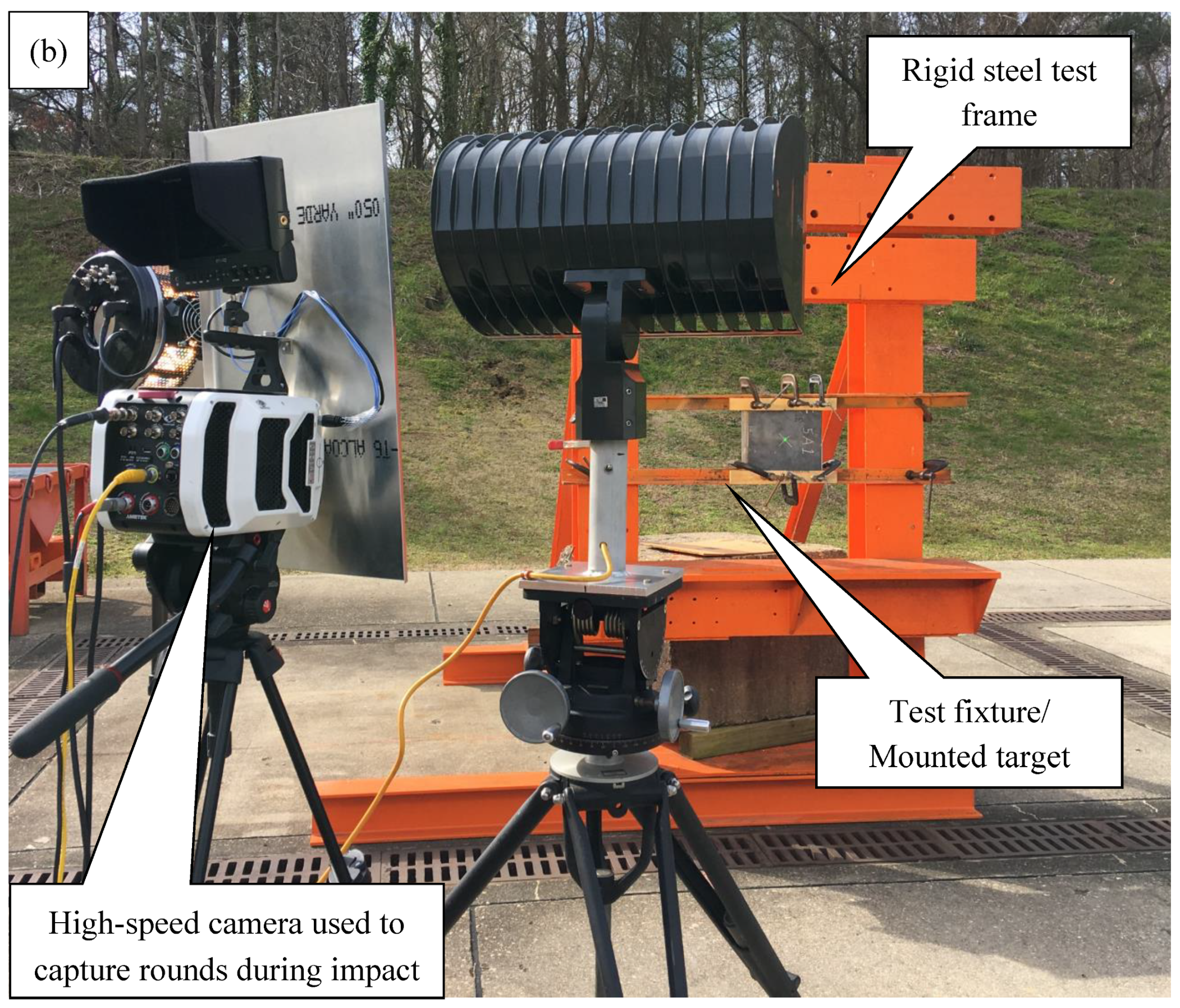
The CMF layered hard armors were placed onto a testing mount 5 m downrange from a Mann gun used to fire the ballistic threats, as shown in Figure 4a. Three velocity chronographs were used to measure the impact velocity of the bullet as it approached the sample. The samples were clamped to a heavy-duty steel structure to support the armors about its outer edges, as can be seen marked in Figure 4b. A high-speed camera was placed facing the target panel and recorded the impact of the projectile while also confirming the obliquity and impact velocity (Figure 4b). A single shot was fired at the center of each armor with a zero-degree obliquity.
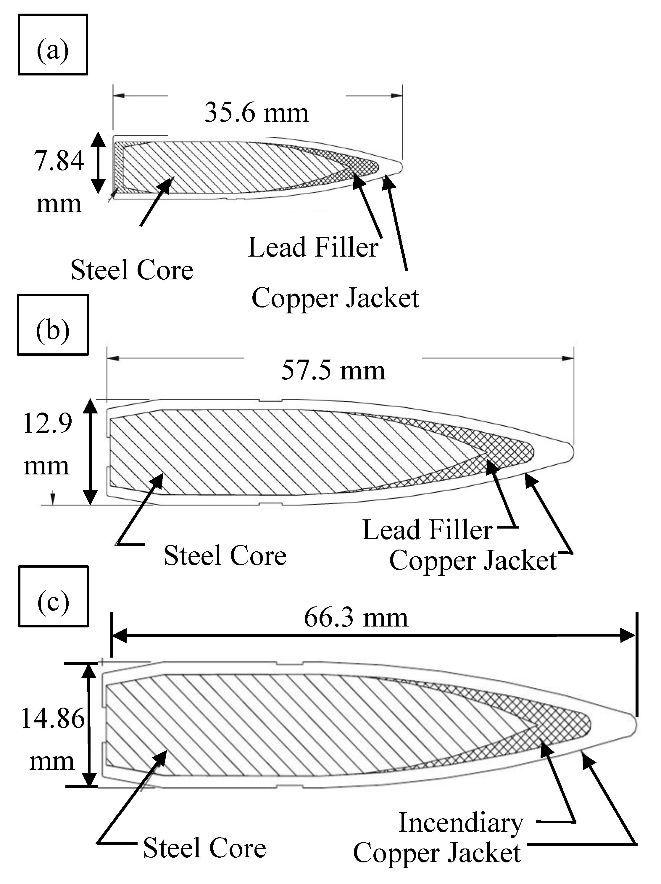
The 14.5 × 114 mm B32 API was chosen for testing in accordance with the North Atlantic Treaty Organization (NATO) standard agreement (STANAG) 4569 Level IV protection [44]. This standard is created for logistic and light armor vehicle (LAV) protection systems and includes larger caliber threats not accounted for in the National Institute of Justice (NIJ) body armor standards [45]. A cross sectional drawing of the 7.62 mm AP, 12.7 mm AP, and 14.5 mm B32 is presented in Figure 5. Each round has a hardened steel core (HRC61-66) surrounded by a lead filler and a brass casing. In addition to the AP penetrator, the 14.5 mm also includes an incendiary charge located at the tip of the projectile that ignites upon impact. Table 1 includes the size and impact energy of the B32 API and compares it with the previously tested 7.62 and 12.7 mm M2 AP [46].
The results of the ballistic impacts against the CMF armors are analyzed using MIL-STD-622F testing procedures and are categorized as either complete penetration (CP) or partial penetration (PP) [47]. The impact is considered PP when the armor is able to stop the impending round, while the test is considered CP when the projectile creates a hole large enough for light to penetrate through the armor. The most popular method of analyzing potential light armors is to determine a V50 as per MIL-STD-622F. The V50 is determined by calculating the arithmetic mean of at least two partial and two complete penetration impact velocities of armors with similar areal densities. The result represents the velocity at which a round has an equal probability of both penetrating and being stopped by the armor. In this study, three arrangements are tested for initial comparison and analysis of the performance of CMF armors against such a large incendiary threat. Although additional testing will be needed to calculate an accurate V50, a preliminary average of the CMF armors against the 14.5 × 114 mm B32 API impact velocity, areal density, and efficiency was calculated for the tests conducted in this study. The results are compared to the performance of CMF armors against various AP threats reported in prior works.

3. Results and Discussion

3.1. 14.5 mm Ballistic Testing Results

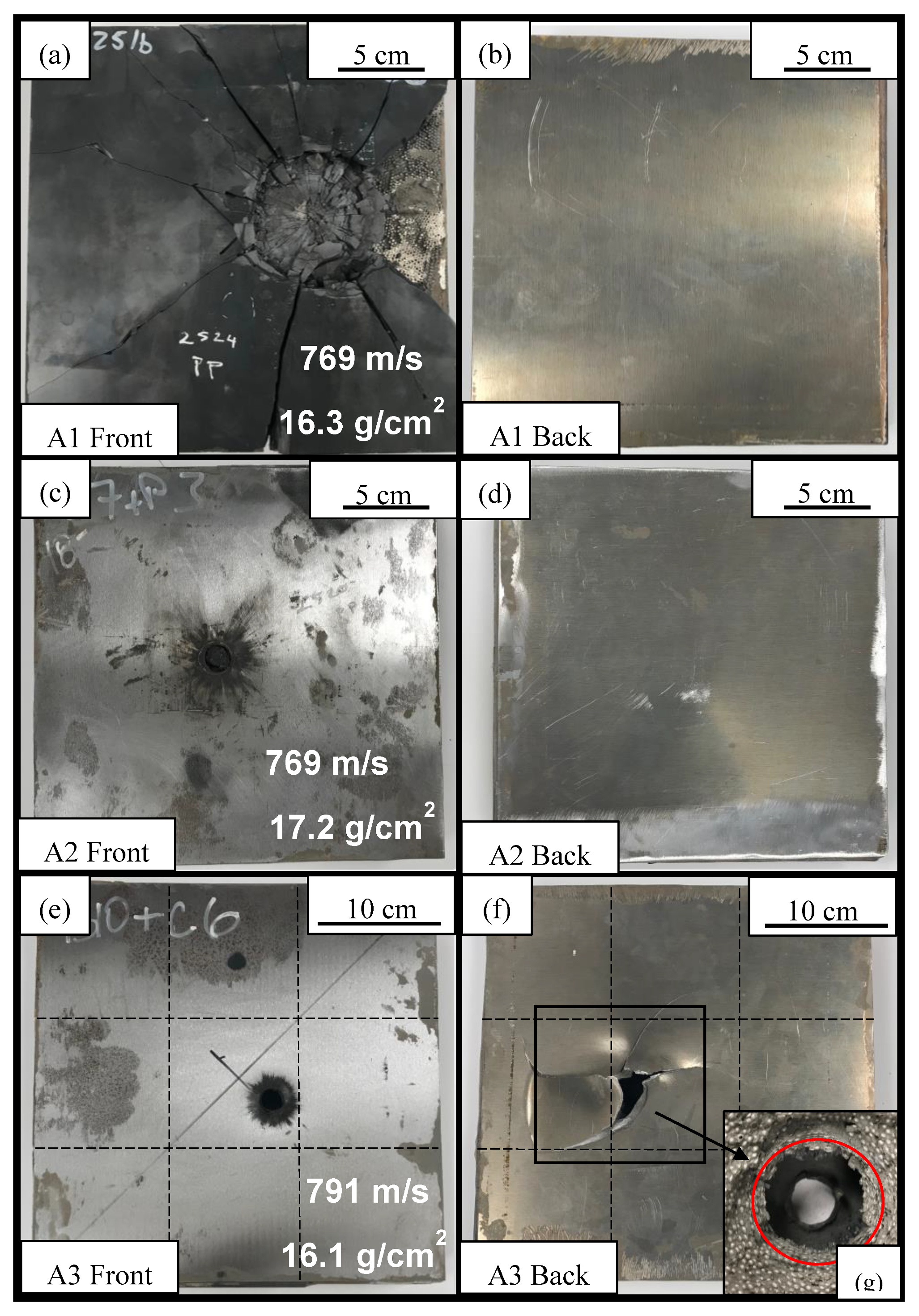
The results of the ballistic testing of CMF hard armors against 14.5 mm threats are presented in Table 2. The tested armors are listed in order of their impact velocity and configuration and compared to standard armors such as RHA and HHA that are established in their military testing standards, MIL-A-12560 [4] and MIL-A-46100 [48], respectively. The kinetic energy of each 14.5 mm round was calculated to be approximately 20 kJ at impact velocities just under 800 m/s. The current test speeds are equivalent to the impact of the 14.5 mm B32 round at a standoff distance of 500 m [44,47]. Two of the tests resulted in partial penetration, while Armor 3 was unable to stop the round. Images of the front and back of each armor are shown in Figure 6. The results are split into two sections where the armor arrangements tested herein are first analyzed and then compared for their benefits and drawbacks. The second section uses previously published data to investigate the performance of CMF armors against increasing threat sizes.

3.1.1. Armor 1: Double-Layered Ceramic-CMF-Al

Testing of Armor 1 resulted in partial penetration of the 14.5 mm API at an impact speed of 769 m/s. The front and back of Armor 1 are presented in Figure 6a,b. As can be seen, the top ceramic faceplate shattered upon impact, with cracks propagating across the entire surface of the panel. The lower ceramic also fractures to a similar extent and is not protected from the impact using a dual ceramic arrangement. Large fragments of ceramic are removed from the first layer about the point of impact, while the broken parts of the second layer have remained intact with the CMF core. The ceramic layer experiences higher levels of fracture due to the incendiary found at the head of the 14.5 mm API. This creates larger fragments along the surface of the armor compared to the testing of previous AP rounds, which leads to delamination of the faceplate, as can be seen along the right side of the armor’s surface. The aluminum backplate shows no sign of impact, confirming that the CMF core was more than enough in conjunction with the double-layered ceramic to stop the API round. This armor seems to be over-designed and a much lower areal density is expected to perform in similar conditions. The fracture of the ceramic may be reduced by replacing the top ceramic with a thin RHA plate to absorb the initial shock and create an armor more compatible with conventional vehicle designs. Armor 2 explores this by using an RHA face sheet in place of one of the ceramic layers.

3.1.2. Armor 2: RHA-Ceramic-CMF-Al

The front and back of Armor 2 are shown in Figure 6c,d. As can be seen, the replacement of one of the ceramic face sheets with a thin RHA layer improved retention of the ceramic fragments and reduced the overall fragmentation of the armor. The effects of the incendiary charge are shown by the black charring around the impact point, and front petaling of the RHA plate (Figure 6c). Armors 1 and 2 were tested at approximately the same impact velocity, 769 m/s. Similar to Armor 1, Armor 2 shows no apparent signs of the impact on the aluminum backplate (Figure 6d) and both armors were able to stop the bullet within the CMF layer. Armor 2 is also over-designed and a much lower areal density may result in partial penetration under similar conditions. The RHA is able to mitigate the incendiary charge of the round more efficiently than the ceramic as no fragmentation or delamination is found along the surface. Although the ceramic performs better than the RHA under compressive loads, the RHA stabilizes the armor as a whole, making it possible for application in the field. Fragments of the hardened core are captured within the CMF layer and no major cracking or failure of the armor can be found away from the point of impact. This is primarily due to the initial mitigation of the incendiary charge by the RHA face sheet and the absorption of the kinetic energy primarily within the CMF layer. The RHA layer increases the areal density of the armor, when compared to Armor 1, but may be used in future CMF armor designs to improve the retention of the ceramic layer and can be further optimized to create similar armors with a higher efficiency.

3.1.3. Armor 3: RHA-Ceramic (Tiles)-CMF-Al

Armor 3 was tested at an impact velocity of 790 m/s, 3% higher than the other armors, and was unable to stop the impending round as the core penetrated the aluminum backplate. The slight variation in impact velocity is expected in this type of ballistic testing and does not seem to be the main reason for complete penetration in Armor 3. The armor had a similar areal density to Armor 1, but with a different face sheet arrangement, while Armors 2 and 3 have similar arrangements of components using steel face sheets. Armor 3 has a thinner ceramic layer than Armor 1, replaced partially by the RHA faceplate, but was unable to stop the round at 790 m/s. The main factor causing complete penetration in Armor 3 was the close proximity of the impact to the seam line between ceramic tiles. The effectiveness of the tiles was limited by the impact close to the seam, leading to premature delamination of the backplate. Separation of the backplate prevented the CMF from fully compressing and maximizing its energy absorption capabilities. The impact and exit points of the round are shown in Figure 6e,f with the dotted lines representing the location of the seams between ceramic tiles that are placed below the RHA faceplate. The multi-tile arrangement has potential to improve the ceramic layer’s energy absorption and crack propagation between tiles, but, as can be seen, is vulnerable to impacts at the seam between tiles making it less effective than a monolithic ceramic plate. The separation of the backplate from Armor 3, (Figure 6f), allowed us to have a better look at the extent of deformation in the CMF layer as seen in Figure 6g. The compressed layer of the CMF core is highlighted by the red circle in Figure 6g. Surrounding the primary point of impact, the CMF layer is compressed and gradually sheared between the matrix and the sphere walls, similar to what has been seen in testing of CMF armors against the 12.7 mm M2 AP [17]. The sheared layers of the CMF failed before they were able to help absorb the kinetic energy of the ballistic impact. Future testing is expected to optimize the interfacial bonding, the design of the lay-up of the armor, and their resulting mass and efficiencies. It should be noted that these are the preliminary results of CMF hard armors against the 14.5 × 114 mm B32 API threat and further optimization and testing would allow for improvements in the performance of the CMF hard armor system towards finalizing an accurate V50.
CMF also has other benefits that meet STANAG armor requirements in addition to its use in ballistic armors against the 14.5 mm B32 API rounds and similar threats. CMF also has a lower thermal conductivity over standard materials often used for combat vehicles and additional radiation shielding, which are passive benefits applicable to combat scenarios and war zones [49,50]. The insulating properties of CMF give military personnel more time to dismount during internal and external fires in combat. Future work should focus on the implementation of vehicle designs and full-scale testing that includes attachment options for both CMF panels and possible applique armors that can bolt or adhere to the exterior of the vehicle’s vulnerable points.

3.2. Comparison to Conventional Armors

3.2.1. Mass Efficiency Ratio (MER)

In order to assess the effectiveness of the CMF armors and compare it to RHA, its mass efficiency ratio (MERCMF) is calculated. The MER compares the armor’s performance to that of RHA at a similar impact velocity of a similar round and determines the armor’s weight savings. In this study, the MERCMF is calculated by dividing the areal density of RHA (ρRHA) required to stop an impending round at a specified velocity by the areal density of the CMF armor (ρCMF) to stop a similar impending round, shown by the equation below:
MERCMF = ρRHACMF
Armors with overall weight savings (MER greater than 1) would potentially improve military vehicles with an increased fuel efficiency, maneuverability, and ability to carry larger payloads.
In order to find ρCMF for Equation (1), first, an approximate V50, noted by V50*, of the CMF armors against the 14.5 × 114 mm B32 API is calculated by finding the arithmetic mean of Armor 2 and Armor 3. The V50* is denoted by an asterisk as only two rounds are used in its calculation and it does not meet the required number of tests for the V50 specifications in MIL-STD-622F. The initial results suggest an average areal density of 16.2 g/cm2 at an average impact velocity of 780 m/s. These values require quadruple testing in order to calculate a more accurate V50 value and validate the current findings.
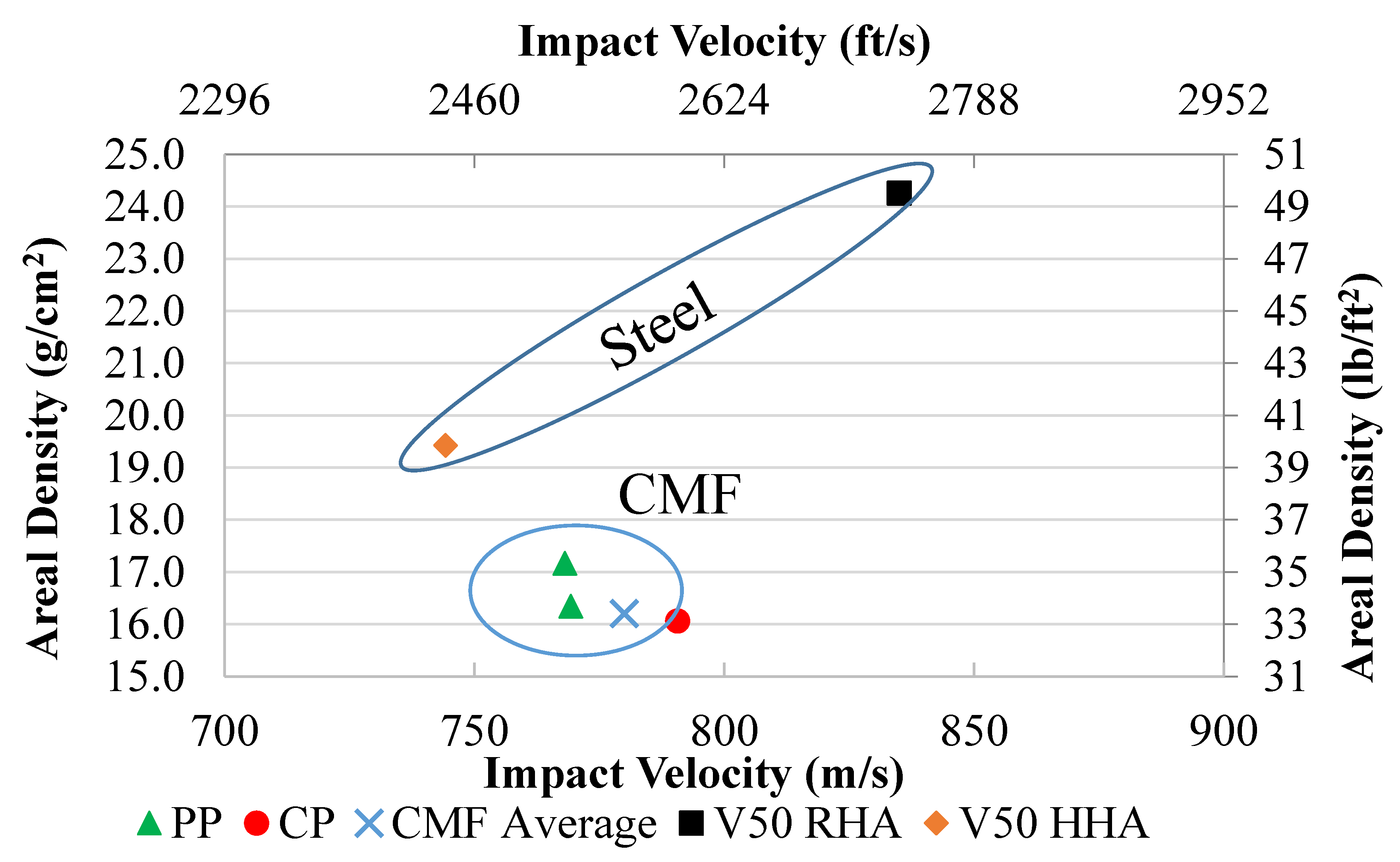
The average performance of the unoptimized CMF armors, however, can be compared to the RHA and HHA performance against the same threat using current data. According to Gooch et al., RHA with an areal density of 24.3 g/cm2 has a V50 of approximately 835 m/s against the 14.5 mm B32 API while HHA has a measured areal density of 19.4 g/cm2 at 744 m/s [4]. The areal density and impact velocity of these armors are plotted in Figure 7 alongside the CMF armors tested in this study for comparison. Although the CMF armors were tested in their unoptimized state and a different impact velocity, the advantage of the CMF armors is apparent. The MER for the tested unoptimized and over-designed CMF armors is calculated to be 1.2 and 1.5 when compared to the HHA and RHA, respectively.

3.2.2. Analytical Energy Absorption

The energy absorption of the CMF layer can be calculated using an analytical method described below. First, the kinetic energy of the impacting round is calculated using classical mechanics assuming a projectile mass of 64.4 g for the 14.5 mm B32 API and the round’s impact velocity. In cases where the bullet is stopped, its entire kinetic energy (EKE) must be dissipated through the erosion of the bullet’s casing and hardened steel core (EBullet), deformation and fracture of the ceramic (ECeramic) and RHA faceplates (ERHA), compression of the CMF core, and yielding of the aluminum backplate (EAluminum). The energy absorbed by the CMF (ECMF) can be determined by subtracting the approximate energy absorbed by all other components of the armor from the energy of the round using Equation (2):
ECMF = EKE − ECeramic − ERHA − EAluminum − EBullet
In order to calculate the energy absorbed by each material, the volumetric energy absorption is calculated using each component’s respective stress–strain curve. The area under the stress–strain curve represents the volumetric strain energy in J/m3 and is calculated using Equation (3):
ω ρ = σ d ε
The material parameters for the ceramic and aluminum backplate are taken from previous work [16,17]. The mechanical properties of the RHA under compressive loads, as it is being used as a faceplate, are approximated using data by Bassim et al. [52]. Once the volumetric strain energy is calculated, it can be multiplied by the volume of material deformed during impact to determine the energy absorbed by each layer. The volume of each layer is approximated using the front and back impact diameters of the armor. Equation (2) is then used to back out the energy that can be attributed to the CMF layer. The fraction of energy absorbed by the CMF layer is calculated by dividing ECMF by EKE. The approximate volumetric energy is also determined by dividing ECMF by the volume of CMF compressed under impact.
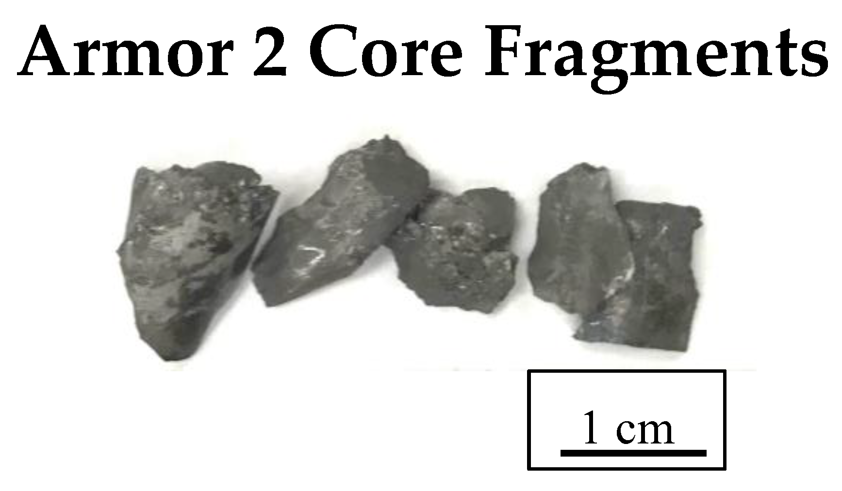
The energy absorption results calculated using the above-mentioned approximation are listed in Table 3. The motion of the ceramic and bullet fragments ejected from the surface of the armor is assumed to make up 4–5% of the overall energy of the impact, given the fragments found following testing, and is included in the energy absorbed by the ceramic layer (ECeramic) [53,54,55]. The hardened steel core fragments retrieved from Armor 2 are used to calculate the amount of energy absorbed by erosion and the fracture of the AP core and are attributed to EBullet. The fragments from Armor 1 were unable to be fully retrieved as both the hardened core and ceramic fragments were ejected from the surface during testing and were not found after testing. The retrieved fragments account for 12.16 g or 30% of the core’s initial mass and are shown in Figure 8. The fractured core provides evidence of the armor appropriately eroding the steel core and the casing being deformed upon impact and is used in calculating the amount of energy attributed to the erosion of the bullet. The calculations indicated that the CMF layer in Armor 1 absorbs 70% of the bullet’s kinetic energy and a volumetric energy absorption of 180 MJ/m3. Similarly, the CMF layer of Armor 2 was calculated to absorb 83% of the kinetic energy, which is equal to a volumetric energy absorption of 243 MJ/m3. The lower energy absorbed by the CMF in Armor 1 is due to the double-layered ceramic used in its structure. There is a benefit in having thinner single-layered ceramic in Armor 2 as the bullet is cradled within the armor, and—more specifically—the CMF layer. It appears that both Armor 1 and Armor 2 are slightly over designed for the 14.7 mm B32 API at the tested impact velocity as the aluminum backplate shows no signs of indentation or fracture.

3.3. Comparison of CMF Armors against Various AP Threats

The data collected were also used to compare the CMF armor’s ability to stop AP threats of different sizes and how their performance changes with increasing size. The percentage of energy absorbed by each layer is compared for the PP tests and their averages calculated for the previous testing of 7.62 [16] and 12.7 mm M2 AP rounds [17] in Table 3, while the energy absorbed by the CMF is plotted in Figure 9 as a function of the kinetic energy of the round. It can be seen that, as the projectile size and impact energy increases, so does the effectiveness of the CMF layer. As the areal density of the armor increases, the percentage of energy absorbed by the CMF also increases linearly from approximately 60% for the 7.62 mm to above 83% for the 14.5 mm rounds. The linear trend is due to the following factors:
  • The increasing impact area of the larger bullets engages a greater number of spheres, improving the cushioning ability of the armor.
  • The increased thickness of the CMF layer in the armor design further helps spread the load through the thickness of the armor, strengthening its performance under compression.
  • A larger secondary impact zone is created as a result of the reflected stress waves in the thicker armors. The secondary impact region supports the primary impact zone around the projectile cores.
Additional information on the armor arrangements tested against the 7.62, 12.7, and 14.5 mm AP threats, including the areal densities and total thicknesses, are compared in Table 4. Due to confidentiality, the exact thicknesses cannot be reported, but a normalized value can be used for comparison. The normalized values in Table 4 are calculated by first finding the average impact energy, thickness, and areal density of the CMF armors against each threat size. The 12.7 mm and 14.5 mm tests are then normalized by dividing their average value by the average value of the armors facing the 7.62 mm AP threat. This gives a direct comparison of the CMF armor variables for the three different AP ballistic threat sizes. From this data, we can see the kinetic energy of the round increases by 3.72 and 4.67 for the 12.7 mm and 14.5 mm threat, respectively, whereas the areal density and total thickness of the armor increase at a slower rate. The total thickness and areal density follow a similar trend for the 12.7 mm AP threat. It can be seen that the capabilities of the armors do not increase linearly with the kinetic energy of the round due to multiple factors. The larger threats carry not only a greater kinetic energy, but also influence a larger volume of material to deform under impact. By incorporating more spheres within the CMF layer and increasing the thickness of each constituent, the armor’s capabilities change depending on the threat size. An important factor to note is that the ceramic, CMF, and backplate thicknesses all remained proportional (excluding Armor 1 using a double ceramic layer). The increase in the impact volume can be seen by analyzing the PP and CP of all three threat types: 7.62, 12.7 mm M2 AP, and the 14.5 mm API.
Samples tested against 7.62 mm M2 AP [16], 12.7 mm M2 AP [17], and 14.5 mm API with similar armor components (ceramic face sheet, CMF core and aluminum backing) are shown next to each other in Figure 10. Further information on the performance of CMF armors against the individual threats can be found in prior publications [16,17]. The first row of Figure 10 shows the front and back of a 25 × 25 cm CMF armor (with an areal density of 6.0 g/cm2) tested against two impacting 7.62 mm AP, both resulting in PP. Figure 10a shows both bullets cradled within the top layer of the armor. A close up view of the center impact is shown in Figure 10c. The impact area is slightly larger than the diameter of the bullet, as the load was spread by the top ceramic layer and created a primary and secondary impact region in the armor, as highlighted by the white and red circles, respectively. The secondary impact region is not much larger than the bullet’s diameter given the relatively thin layer of ceramic. Moreover, tensile stresses created due to the sudden changes in mechanical impedance between various layers of the armor are reflected from the back into the armor towards the impact face. The size of the secondary impact zone is a function of the armor thickness and the mechanical impedance of the components. Since all components are the same in different CMF armors, their mechanical impedance would be similar and as the result, the only factor affecting the secondary impact area is the thickness of different components of the armor, especially the CMF layer (and its areal density). The thicker the CMF (or higher areal density), the larger the secondary impact zone, which leads to a higher energy absorption percentage in the CMF layer. Since the armor against 7.62 rounds are the thinnest, the secondary impact zone is the smallest as can be seen in Figure 10c. The CMF armor also offers a multi-shot capability that is unique to the yielding of CMF as neither soft nor hard armors can offer such an extensive multi-shot capability.
Figure 10d–f present similar images of a slightly thicker CMF armor (with an areal density of 10.7 g/cm2) tested against the 12.7 mm M2 AP threat with PP. The same cradle behavior is seen, but additional ceramic on the top surface of the armor is removed with a larger crater surrounding the AP core. The secondary region of compressed CMF is created as the load is reflected from the back of the armor. The secondary region is larger than that seen in the 7.62 mm round. There are two mechanisms at work that lead to a larger primary and secondary loading region in the CMF layer. First, the armors facing the 12.7 mm AP threats used a thicker ceramic layer (as can be seen by the higher areal density of the armor) that spreads the load to a larger surface area of CMF due to the Hertzian cone formation through the ceramic’s thickness [16,56]. Second, the blast waves from a larger caliber threat carry a higher kinetic energy that is reflected within the thicker armor (with higher areal density). An increase can be seen in both the secondary impact area and energy absorbed by the CMF when compared to the 7.62 mm round.
Images of Armor 3 after impact with the 14.5 mm API are once again presented in Figure 10g–i with a larger image of the exposed CMF layer on the back of the armor in Figure 10i. Similar to the 12.7 mm AP round, the number of spheres affected by the impact further increases when facing a large threat such as the 14.5 mm round with a thicker ceramic and CMF layer. The increased size of the round along with the use of a thicker ceramic layer spreads the impact energy over a larger area of CMF, engaging a larger number of hollow spheres to absorb the impact energy. The secondary impact area is affected by the larger thickness of CMF layer as well as the additional incendiary charge that is ignited upon impact. The explosive tip releases a shockwave that travels through the armor, further expanding the Hertzian cone formation in the ceramic layer. A constant trend can once again be seen when comparing the armors against smaller threats as the secondary impact region grows with threat size and is thought to be one of the main reasons for the increase in the percentage of energy absorbed by the CMF layer.

4. Conclusions

SS-CMF hard armors were manufactured and tested against a 14.5 × 114 mm B32 API ballistic threat. Three arrangements were tested, the first being a conventional hard armor with a double-layered ceramic faceplate, a SS-CMF core, and a thin aluminum backplate. The other two armors used much thinner ceramic layers and included a thin RHA plate placed atop the ceramic. The CMF armors were able to stop two of the three tested rounds at impact speeds between 770 and 790 m/s. The RHA layer was able to mitigate the incendiary impact of the round while the ceramic and CMF absorb the AP core’s kinetic energy. The second arrangement (Armor 2) using an RHA faceplate, single ceramic, CMF core, and aluminum backplate was found to be the most efficient arrangement. The dual ceramic layer shows fractures within both layers, while the individual tile arrangement was found to be vulnerable at the seam line between tiles. The average mass efficiency of the unoptimized CMF armor is calculated from the initial results, with a MER of 1.5 at 780 m/s impact velocity when compared to RHA. The CMF layer was calculated to absorb between 70–83% of the bullet’s kinetic energy.
When compared to a variety of ballistic threats, the CMF armors continue to show strengthening as the size and impact energy of the round increases. The increasing impact area of the larger bullets also engages a higher number of spheres, improving the cushioning ability of the armor. As the impact area increases, the hardened steel core is less likely to pierce the CMF layer and is stopped within the armor due to the growth of the secondary impact region. The spheres within the secondary impact region help support the primary point of impact of the projectile core and improve the overall performance of the CMF layer. Further testing and optimization of CMF armors is expected to improve their mass efficiency. However, it is important to note, given the current data, that the armors show improvement over conventional RHA and offer a weight reduction that is vital for the advancement of today’s military vehicles. Future armors can be built to maximize the advantages of CMF due to its high energy absorption capabilities and cushioning of the AP core.

Author Contributions

Conceptualization, A.R.; methodology, A.R. and M.P.; formal analysis, A.R., and J.M.; writing—original draft preparation, J.M. and A.R.; writing—review and editing, A.R. and M.P.; project administration, A.R.; funding acquisition, A.R. and M.P. All authors have read and agreed to the published version of the manuscript.

Funding

The research presented was performed using funding granted by the Joint Aviation Survivability Program (JASP) (award #W911W6-15-D-0001-0001).

Acknowledgments

The authors would like to thank the team who facilitated the testing at the Combat Capabilities Development Command (CCDC) Aviation & Missile Center, (AvMC) Aviation Development Directorate (ADD).

Conflicts of Interest

Afsaneh Rabiei has 4 issued patents on composite metal foams. These patents have been released to a start-up company in which she is the founder and shareholder.

References

  1. Ash, R. Lightweight Ballistic Composites: Military and Law-Enforcement Applications: Vehicle Armors, 2nd ed.; Bhatnagar, A., Ed.; Woodhead Publishing: Sawston/Cambridge, UK, 2016. [Google Scholar]
  2. Medvedovski, E. Ballistic performance of armour ceramics: Influence of design and structure. Part 1. Ceram. Int. 2010, 36, 2103–2115. [Google Scholar] [CrossRef]
  3. Medvedovski, E. Ballistic performance of armour ceramics: Influence of design and structure. Part 2. Ceram. Int. 2010, 36, 2117–2127. [Google Scholar] [CrossRef]
  4. Military, U.S. Armor Plate, Steel, Wrought, Homogeneous, MIL-DTL-12560K (MR) (For use in Combat-Vehicles and for Ammunition Testing); Army Research Laboratory (US), Aberdeen Proving Ground: Aberdeen, MD, USA, 2013.
  5. Kiliç, N.; Ekici, B. Ballistic resistance of high hardness armor steels against 7.62 mm armor piercing ammunition. Mater. Des. 2013, 44, 35–48. [Google Scholar] [CrossRef]
  6. Ryan, S.; Li, H.; Edgerton, M.; Gallardy, D.; Cimpoeru, S. Ballistic evaluation of an australian ultra-high hardness steel. In Proceedings of the 29th International Symposium on Ballistics, Edinburgh, UK, 9–13 May 2016; DEStech Publications, Inc.: Edinburgh, UK, 2016; Volume 2, pp. 1773–1778. [Google Scholar]
  7. Shen, Z.; Hu, D.; Yang, G.; Han, X. Ballistic reliability study on SiC/UHMWPE composite armor against armor-piercing bullet. Compos. Struct. 2019, 213, 209–219. [Google Scholar] [CrossRef]
  8. Savio, S.G.; Ramanjaneyulu, K.; Madhu, V.; Bhat, T.B. An experimental study on ballistic performance of boron carbide tiles. Int. J. Impact Eng. 2011, 38, 535–541. [Google Scholar] [CrossRef]
  9. Zhang, X.F.; Li, Y.C. On the comparison of the ballistic performance of 10% zirconia toughened alumina and 95% alumina ceramic target. Mater. Des. 2010, 31, 1945–1952. [Google Scholar] [CrossRef]
  10. Pawar, M.J.; Patnaik, A.; Biswas, S.K.; Pandel, U.; Bhat, I.K.; Chatterjee, S.; Mukhopadhyay, A.K.; Banerjee, R.; Babu, B.P. Comparison of ballistic performances of Al2O3 and AlN ceramics. Int. J. Impact Eng. 2016, 98, 42–51. [Google Scholar] [CrossRef]
  11. Jones, T.L.; Placzankis, B.E. The Examination of the Aluminum Alloy 7017 as a Replacement for the Aluminum Alloy 7039 in Lightweight Armor Systems; ARL-TR-7727; Army Research Laboratory (US): Aberdeen, MD, USA, 2016. [Google Scholar]
  12. Übeyli, M.; Deniz, H.; Demir, T.; Ögel, B.; Gürel, B.; Keleş, Ö. Ballistic impact performance of an armor material consisting of alumina and dual phase steel layers. Mater. Des. 2011, 32, 1565–1570. [Google Scholar] [CrossRef]
  13. Diederen, M.; Broos, J.P.F.; Trigt, S.N. Van Ballistic Protection Against Armour Piercing Projectiles Using Titanium Base Armour. Cost Eff. Appl. Titan. Alloys Mil. Platf. 2001, 99, 7–11. [Google Scholar]
  14. Liu, W.; Chen, Z.; Chen, Z.; Cheng, X.; Wang, Y.; Chen, X.; Liu, J.; Li, B.; Wang, S. Influence of different back laminate layers on ballistic performance of ceramic composite armor. Mater. Des. 2015, 87, 421–427. [Google Scholar] [CrossRef]
  15. Mikulikova, R.; Ridky, R.; Rolc, S.; Krestan, J. Influence of impact velocity and steel armour hardness on breakage of projectile 14.5 × 114 API/B32. Adv. Mil. Technol. 2018, 13, 59–69. [Google Scholar] [CrossRef] [Green Version]
  16. Garcia-Avila, M.; Portanova, M.; Rabiei, A. Ballistic performance of composite metal foams. Compos. Struct. 2015, 125, 202–211. [Google Scholar] [CrossRef]
  17. Marx, J.; Portanova, M.; Rabiei, A. Ballistic performance of composite metal foam against large caliber threats. Compos. Struct. 2019, 225, 111032. [Google Scholar] [CrossRef]
  18. Vendra, L.J.; Rabiei, A. A study on aluminum-steel composite metal foam processed by casting. Mater. Sci. Eng. A 2007, 465, 59–67. [Google Scholar] [CrossRef]
  19. Brown, J.A.; Vendra, L.J.; Rabiei, A. Bending properties of Al-steel and steel-steel composite metal foams. Metall. Mater. Trans. A Phys. Metall. Mater. Sci. 2010, 41, 2784–2793. [Google Scholar] [CrossRef]
  20. Rabiei, A.; Garcia-Avila, M. Effect of various parameters on properties of composite steel foams under variety of loading rates. Mater. Sci. Eng. A 2013, 564, 539–547. [Google Scholar] [CrossRef]
  21. Alvandi-Tabrizi, Y.; Whisler, D.A.; Kim, H.; Rabiei, A. High strain rate behavior of composite metal foams. Mater. Sci. Eng. A 2015, 631, 248–257. [Google Scholar] [CrossRef]
  22. Marx, J.; Portanova, M.; Rabiei, A. A study on blast and fragment resistance of composite metal foams through experimental and modeling approaches. Compos. Struct. 2018, 194, 652–661. [Google Scholar] [CrossRef]
  23. Rabiei, A.; Vendra, L.J. A comparison of composite metal foam’s properties and other comparable metal foams. Mater. Lett. 2009, 63, 533–536. [Google Scholar] [CrossRef]
  24. Vendra, L.; Rabiei, A. Evaluation of modulus of elasticity of composite metal foams by experimental and numerical techniques. Mater. Sci. Eng. A 2010, 527, 1784–1790. [Google Scholar] [CrossRef]
  25. Rabiei, A.; Neville, B.; Reese, N.; Vendra, L. New composite metal foams under compressive cyclic loadings. Mater. Sci. Forum 2007, 539–543, 1868–1873. [Google Scholar] [CrossRef]
  26. Neville, B.P.; Rabiei, A. Composite metal foams processed through powder metallurgy. Mater. Des. 2008, 29, 388–396. [Google Scholar] [CrossRef]
  27. Marx, J.; Rabiei, A. Overview of Composite Metal Foams and Their Properties and Performance. Adv. Eng. Mater. 2017, 19, 1600776. [Google Scholar] [CrossRef]
  28. Szyniszewski, S.T.; Smith, B.H.; Hajjar, J.F.; Schafer, B.W.; Arwade, S.R. The mechanical properties and modeling of a sintered hollow sphere steel foam. Mater. Des. 2014, 54, 1083–1094. [Google Scholar] [CrossRef] [Green Version]
  29. Ruan, D.; Lu, G.; Chen, F.L.; Siores, E. Compressive behaviour of aluminium foams at low and medium strain rates. Compos. Struct. 2002. [Google Scholar] [CrossRef]
  30. Miyoshi, T.; Itoh, M.; Akiyama, S.; Kitahara, A. Aluminum foam, “ALPORAS”: The production process, properties and applications. Mater. Res. Soc. Symp. Proc. 1998, 521, 133–137. [Google Scholar] [CrossRef]
  31. Marx, J.; Rabiei, A. Study on the Microstructure and Compression of Composite Metal Foam Core Sandwich Panels. Metall. Mater. Trans. A 2020. [Google Scholar] [CrossRef]
  32. Szlancsik, A.; Katona, B.; Bobor, K.; Májlinger, K.; Orbulov, I.N. Compressive behaviour of aluminium matrix syntactic foams reinforced by iron hollow spheres. Mater. Des. 2015, 83, 230–237. [Google Scholar] [CrossRef] [Green Version]
  33. Rizzi, E.; Papa, E.; Corigliano, A. Mechanical behavior of a syntactic foam: Experiments and modeling. Int. J. Solids Struct. 2000. [Google Scholar] [CrossRef]
  34. Gupta, N.; Kishore; Woldesenbet, E.; Sankaran, S. Studies on compressive failure features in syntactic foam material. J. Mater. Sci. 2001. [Google Scholar] [CrossRef]
  35. Balch, D.K.; O’Dwyer, J.G.; Davis, G.R.; Cady, C.M.; Gray, G.T., III; Dunand, D.C. Plasticity and damage in aluminum syntactic foams deformed under dynamic and quasi-static conditions. Mater. Sci. Eng. A 2005, 391, 408–417. [Google Scholar] [CrossRef]
  36. Rohatgi, P.K.; Guo, R.Q.; Iksan, H.; Borchelt, E.J.; Asthana, R. Pressure infiltration technique for synthesis of aluminum–fly ash particulate composite. Mater. Sci. Eng. A 1998, 244, 22–30. [Google Scholar] [CrossRef]
  37. Mondal, D.P.; Das, S.; Ramakrishnan, N.; Uday Bhasker, K. Cenosphere filled aluminum syntactic foam made through stir-casting technique. Compos. Part A Appl. Sci. Manuf. 2009. [Google Scholar] [CrossRef]
  38. Orbulov, I.N.; Ginsztler, J. Compressive characteristics of metal matrix syntactic foams. Compos. Part A Appl. Sci. Manuf. 2012. [Google Scholar] [CrossRef] [Green Version]
  39. Gupta, N.; Rohatgi, P.K. Metal Matrix Syntactic Foams: Processing, Microstructure, Properties and Applications; DEStech Publications, Inc.: Lancaster, PA, USA, 2014; ISBN 1932078835. [Google Scholar]
  40. Vendra, L.J. Processing and Characterization of Aluminum-Steel Composite Metal Foams. Ph.D. Thesis, North Carolina State University, NCSU ETD Repository, Raleigh, NC, USA, 2009. [Google Scholar]
  41. Rabiei, A. Composite Metal Foam and Methods of Preparation Thereof. U.S. Patent 9208912B2, 8 December 2015. [Google Scholar]
  42. Demir, T.; Übeyli, M.; Yıldırım, R.O. Investigation on the ballistic impact behavior of various alloys against 7.62mm armor piercing projectile. Mater. Des. 2008, 29, 2009–2016. [Google Scholar] [CrossRef]
  43. Gooch, W.A.; Burkins, M.S.; Squillacioti, R.J. Ballistic testing of commercial aluminum alloys and alternate processing techniques to increase the availability of aluminum armor. In Proceedings of the 23rd International Symposium on Ballistics, Tarragona, Spain, 16–20 April 2007; pp. 981–988. [Google Scholar]
  44. NATO. NATO: Protection Levels for Occupants of Armoured Vehicles, STANAG 4569, 3rd ed.; NATO: Brussels, Belgium, 2014. [Google Scholar]
  45. US Department of Justice Ballistic Resistance of Body Armor NIJ Standard 0101.06. 2008. Available online: https://www.ncjrs.gov/pdffiles1/nij/183651.pdf (accessed on 1 December 2019).
  46. Gooch, W.; Showalter, D.; Burkins, M.; Montgomery, J.; Squillacioti, R.; Nichols, A.; Martin, L.; Bailey, R.; Swiatek, G. Development and ballistic testing of a new class of auto-tempered high hard steels under military specification MIL-DTL-46100E. TMS Annu. Meet. 2009, 3, 321–328. [Google Scholar]
  47. Defense, D. Mil-Std-662F Test Method Standard V 50 Ballistic Test for Armor; Army Research Laboratory (US): Aberdeen, MD, USA, 1997. [Google Scholar]
  48. Military Specification MIL-DTL-46100E (MR), Armor Plate, Steel, Wrought, High-Hardness; Army Research Laboratory (US), Aberdeen Proving Ground: Aberdeen, MD, USA, 2008.
  49. Chen, S.; Bourham, M.; Rabiei, A. Attenuation efficiency of X-ray and comparison to gamma ray and neutrons in composite metal foams. Radiat. Phys. Chem. 2015. [Google Scholar] [CrossRef] [Green Version]
  50. Chen, S.; Marx, J.; Rabiei, A. Experimental and computational studies on the thermal behavior and fire retardant properties of composite metal foams. Int. J. Therm. Sci. 2016, 106, 70–79. [Google Scholar] [CrossRef] [Green Version]
  51. Gooch, W.; Burkins, M.; Squillacioti, R.; Koch, R.-M.S.; Oscarsson, H.; Nash, C. Ballistic Testing of Swedish Steel ARMOX Plate for US Armor Applications Ballistic Testing of Swedish Steel Armox® Plate for U.S. Armor Applications. In Proceedings of the 21st International Symposium on Ballistics, Adelaide, South Australia, 19–23 April 2004; pp. 19–23. [Google Scholar]
  52. Bassim, M.N.; Odeshi, A.G.; Bolduc, M. Deformation and failure of a rolled homogeneous armour steel under dynamic mechanical loading in compression. In Proceedings of the 12th International Conference on ‘Fracture’, New York, NY, USA, 12–17 July 2009; Volume 5, pp. 3464–3473. [Google Scholar]
  53. Naik, N.K.; Kumar, S.; Ratnaveer, D.; Joshi, M.; Akella, K. An energy-based model for ballistic impact analysis of ceramic-composite armors. Int. J. Damage Mech. 2013, 22, 145–187. [Google Scholar] [CrossRef]
  54. Chocron Benloulo, I.S.; Sánchez-Gálvez, V. A new analytical model to simulate impact onto ceramic/composite armors. Int. J. Impact Eng. 1998, 21, 461–471. [Google Scholar] [CrossRef]
  55. López-Puente, J.; Arias, A.; Zaera, R.; Navarro, C. The effect of the thickness of the adhesive layer on the ballistic limit of ceramic/metal armours. An experimental and numerical study. Int. J. Impact Eng. 2005, 32, 321–336. [Google Scholar] [CrossRef] [Green Version]
  56. Fountzoulas, C.G.; LaSalvia, J.C. Simulation of the Ballistic Impact of Tungsten-Based Penetrators on Confined Hot-Pressed Boron Carbide Targets. In Advances in Ceramic Armor VII: Ceramic Engineering and Science Proceedings; The American Ceramic Society: Columbus, OH, USA, 2011; Volume 32, pp. 261–269. [Google Scholar] [CrossRef]
Figure 1. Quasi-static compressive stress–strain curve for steel–steel composite metal foam (SS-CMF) and Al-S CMF compared to bulk aluminum, steel, and other metal foams [25,26,28,29,30,31,32].
Jcs 04 00176 g001
Figure 2. (a) Digital image showing a cut surface and structure of the SS-CMF plate. (b,c) SEM imaging of SS-CMF showing its general microstructure. The sectioned hollow metal spheres shown in (b) are surrounded by a metallic matrix and (c) shows a zoomed in image of the matrix region between the sphere walls, outlined by the white box in 2b.
Jcs 04 00176 g002
Figure 3. Exploded view diagram showing the arrangement of the CMF armors using (a) a two-layer ceramic face sheet, (b) a thin rolled homogeneous armor (RHA) faceplate above one ceramic layer, and (c) RHA above a layer of individual ceramic tiles. Note that the thicknesses and sizing are not to scale.
Jcs 04 00176 g003
Figure 4. (a) Ballistic testing set up showing the arrangement of the target panel placed downrange from the Mann gun, used to fire the threat, as well as the velocity chronographs and high-speed camera used to track the impact; (b) a closeup of the target fixture, rigid steel frame and the high-speed camera to capture the rounds at the point of impact.
Jcs 04 00176 g004aJcs 04 00176 g004b
Figure 5. Cross section drawing of the (a) 7.62 × 63 mm M2 AP, (b) 12.7 × 99 M2 AP, and (c) 14.5 × 114 mm B32 armor-piercing incendiary (API) projectiles [46] that are used for testing CMF armors.
Jcs 04 00176 g005
Figure 6. Digital images of the front (a,c,e) and back (b,d,f) of Armors 1, 2, and 3 following ballistic testing as well as additional images of the compressed spheres (g) in Armor 3. The CMF layer is exposed due to slight delamination of the aluminum backplate.
Jcs 04 00176 g006
Figure 7. Results of the 14.5 × 114 mm B32 API testing plotted alongside V50 values for both RHA and HHA [4,48,51].
Jcs 04 00176 g007
Figure 8. Fragments of the fractured steel core retrieved from Armor 2 (PP) following testing.
Jcs 04 00176 g008
Figure 9. Percentage of energy absorbed by the CMF layer as a function of the impact energy imparted by each ballistic threat. The linear fit between the 7.62 [16] and 12.7 mm [17] AP data shows how the 14.5 × 114 mm B32 API data currently compare with its higher impact energy.
Jcs 04 00176 g009
Figure 10. Digital images of the front and back of the layered SS-CMF armors, highlighting the impact region after testing against a (ac) 7.62 mm M2 AP, (df) 12.7 mm M2 AP, and (gi) 14.5 mm B32 API.
Jcs 04 00176 g010
Table 1. Projectile and core size for each of the tested ballistic rounds and their associated impact energies [46].
Projectile Length (mm)Projectile Diameter (mm)Projectile Mass (g)Core Length (mm)Core Diameter (mm)Core Mass (g)Core MaterialImpact Energy
(kJ)
(@ 750–900 m/s)
7.62 × 63 mm M2 AP
(0.30 Cal)
35.37.8510.827.46.25.3Hardened Steel3–4
12.7 × 99 mm M2 AP
(0.50 Cal)
58.712.9845.945.910.925.9Hardened Steel13–19
14.5 × 114 mm
B32 API
66.314.964.253.112.441.0Hardened Steel18–26
Table 2. Summary of ballistic testing of CMF armors against the 14.5 × 114 mm B32 round.
Areal Density (g/cm2) [lb./ft2]Impact Velocity (m/s)Bullet Kinetic Energy (J)PP/CP
Armor 116.3 [33.5]76919,057PP
Armor 217.2 [35.2]76919,057PP
Armor 316.1 [32.9]79120,129CP
Average16.5 [33.8]77619,274-
HHA19.4 [39.7]74417,823V50 [4]
RHA24.3 [49.8]83522,451V50 [48]
Table 3. Percentage of energy absorbed by a CMF armor each layer for partial penetration (PP) impacts against multiple sized rounds.
ArmorAreal Density (g/cm2)
[lb/ft2]
Average Round Velocity
(m/s)
Total Energy of the Round (J)Percentage of Round Energy Absorbed by:
Ceramic and Motion of Fragment Cloud %Bullet
%
Backplate %RHA
%
CMF
%
Armor 116.3 [33.5]76919,0572721-70
Armor 217.2 [35.2]76919,0571321183
7.62 × 63 mm M2 AP [16]5.9 [12.1]867408191516-60
12.7 × 99 mm M2 AP [17]10.3 [21.1]80415,2081724-77
Table 4. Properties of CMF armors against the 12.7 mm and 14.5 mm AP threats when normalized by the average values of the 7.62 mm AP armors [16,17].
TableNormalized Energy of the RoundNormalized Total ThicknessNormalized Areal Density
7.62 × 63 mm M2 AP [16]1.001.001.00
12.7 × 99 mm M2 AP [17]3.721.601.77
14.5 × 114 mm B32 API4.672.312.90
Publisher’s Note: MDPI stays neutral with regard to jurisdictional claims in published maps and institutional affiliations.