Article

Modeling and Two-Step Homogenization of Aperiodic Heterogenous 3D Four-Directional Braided Composites

Department of Mechanical Engineering, Inha University, 100 Inha-ro, Michuhol-gu, Incheon 22212, Korea
*
Author to whom correspondence should be addressed.
J. Compos. Sci. 2020, 4(4), 179; https://doi.org/10.3390/jcs4040179
Submission received: 8 October 2020 / Revised: 22 November 2020 / Accepted: 25 November 2020 / Published: 27 November 2020
(This article belongs to the Special Issue Advanced Fiber Reinforced Polymer Composites)

Abstract

:
The mechanical properties of the material are essential to identify the material behavior of the structure. Predicting four-directional braided composites’ mechanical properties based on accurate modeling is an essential issue among researchers. In this research, the principle of minimum energy loss-based mechanics of structure genome was used for the two-step homogenization of three-dimensional (3D) four-directional braided composites. In the first step homogenization, the micro-scale model’s effective mechanical properties were decided by considering fibers and matrix; in the second step homogenization, the final effective mechanical properties of the meso-scale model were obtained by considering yarns and matrix. TexGen python script was implemented for accurate modeling of 3D four-directional braided cells with jamming effects. The current process sustainability was validated for 3D four-directional braided polymer matrix composites (PMCs) material by available finite element analysis (FEA) and experimental literature. The method is further extended for 3D four-directional braided ceramic matrix composites (CMCs) to confirm its versatility for standard composites. A commercial FEA was also performed on the meso-scale braided cell to validate the two-step homogenization results. This research explored fast and more accurate modeling and analysis techniques for 3D four-directional braided composites.

1. Introduction

The three-dimensional (3D) braided composites are the important textile composite members. Primarily, 3D four-directional braiding permits tailoring of the material to achieve desirable mechanical properties such as high stiffness and strength [1,2]. In practice, the mechanical characteristics of braided composites mostly depend on their internal braiding structures. In modeling concern, Earlier Ko [3] provided a method to model 3D braided unit cell by the concept of average cosine [3]. Other researchers also introduced different models like the fiber interlock model [4], fiber inclined model [5], helix geometry model [6,7], and three-unit cell model [8,9]. The curved nature of fiber bundles, also considered by researchers [10]. Chen et al. [11] worked on the fiber bundle trajectory in a different region. Meanwhile, some software were developed to build the structures of textiles composites. Verpoest and Lomov developed a Wise-tex [12], and composite research group developed TexGen at the University of Nottingham [13] for modeling 2D or 3D textiles composites. Besides the curved trajectory of yarns and fibers, their cross-sectional shape was also considered; recently, 3D braided rectangular [14,15,16] and tabular [17] composite meso models were presented. Further, different shapes of yarn, i.e., circular [7], polygon [18], and elliptical [17,19], were considered by researchers. Both modeling and analysis techniques are essential simultaneously for better performance prediction.
In analysis concern, the mechanical behavior of composites could be predicted by many methods such as the elastic strain energy approach [4], classical lamination theory [20], stiffness averaging method [21], three-unit cell model [8], and mixed volume averaging method [22]. Even the analytical techniques are fast, but the characteristics of 3D braided composite’s fabric yarns spread along multi-directions and interlace with each other make it difficult to analyze. Also, analytical methods only can calculate the value of elastic constants, and it is difficult to obtain other mechanical characteristics like stress behavior (i.e., the value of stress plot at any section) from the micro-structures [23,24,25,26]. An experimental investigation is also a time-consuming and costly task because of its complexity. The finite element analysis (FEA) on the macro composite may not be accurate because of composite materials’ heterogeneity. Most of the above-mentioned modeling and analysis techniques struggle with accuracy and massive computing and calculation time. Still, the research continues to find out fast and accurate modeling and analysis techniques. For understanding the 3D braided composites at the macro-scale, the micro-scale level design can be a crucial tool [27,28,29]. For this purpose, multi-scale modeling (micro to meso) is the most promising way to capture details of a braided composite structure. The strategy of multi-scale modeling has shown in Figure 1. The micro-scale model introduces fibers and their distribution in the yarn (fiber bundles). Yarns characterize braided composites’ braiding pattern, which is the essential element in the meso-scale. The macro-scale model is the real structure at this scale, it can be treated equally to a continuous structure. In the modeling step, it is the primary concern to cover all process details of materials. Besides, in the analysis part, calculating the material’s correct behavior from the well-defined model is essential. After multi-scale (micro and meso) modeling, it is suitable to apply the homogenization theory at each scale to predict the mechanical performance of 3D composites.
To consider the above facts, recently, researchers have introduced a semi-analytical method for heterogeneous material, based on the principle of minimum energy loss [30,31,32]. Importantly, this semi-analytical approach, namely, mechanics of structure genome (MSG), is accurate, less-time consuming, and able to calculate the elastic stiffness constants for periodic and aperiodic heterogeneous materials [33,34,35].
The present paper provides a multi-scale modeling and homogenization method to predict 3D four-directional braided composites’ accurate mechanical behavior. In the modeling part, a micro-scale and 3D four-directional braided meso-scale model was implemented. The meso-scale model incorporated with squeezing effects by TexGen python code. A semi-analytical method based on the MSG was conducted in Ansys-SwiftComp for micro and meso-scale homogenization in the analysis part. The elastic stiffness constants were calculated for 3D four-directional braided polymer matrix composites (PMCs, epoxy resin/T300 carbon fiber) to validate this method for braided textile because of the availability of literature for this material using different methods.
After verifying the current process for four-directional braided PMCs, this method was extended for 3D four-directional braided CMCs (silicon carbide/T300 carbon fiber). Conventional FEA was also conducted on the same meso-scale 3D four-directional braided model to verify the predicted results from the current applied homogenization process. This research strategy guided time-saving and efficient analysis and modeling technique for 3D four-directional braided composites.

2. Modeling, Homogenization, and Finite Element Analysis

2.1. Modeling of 3D Four-Directional Braided Unit Cell

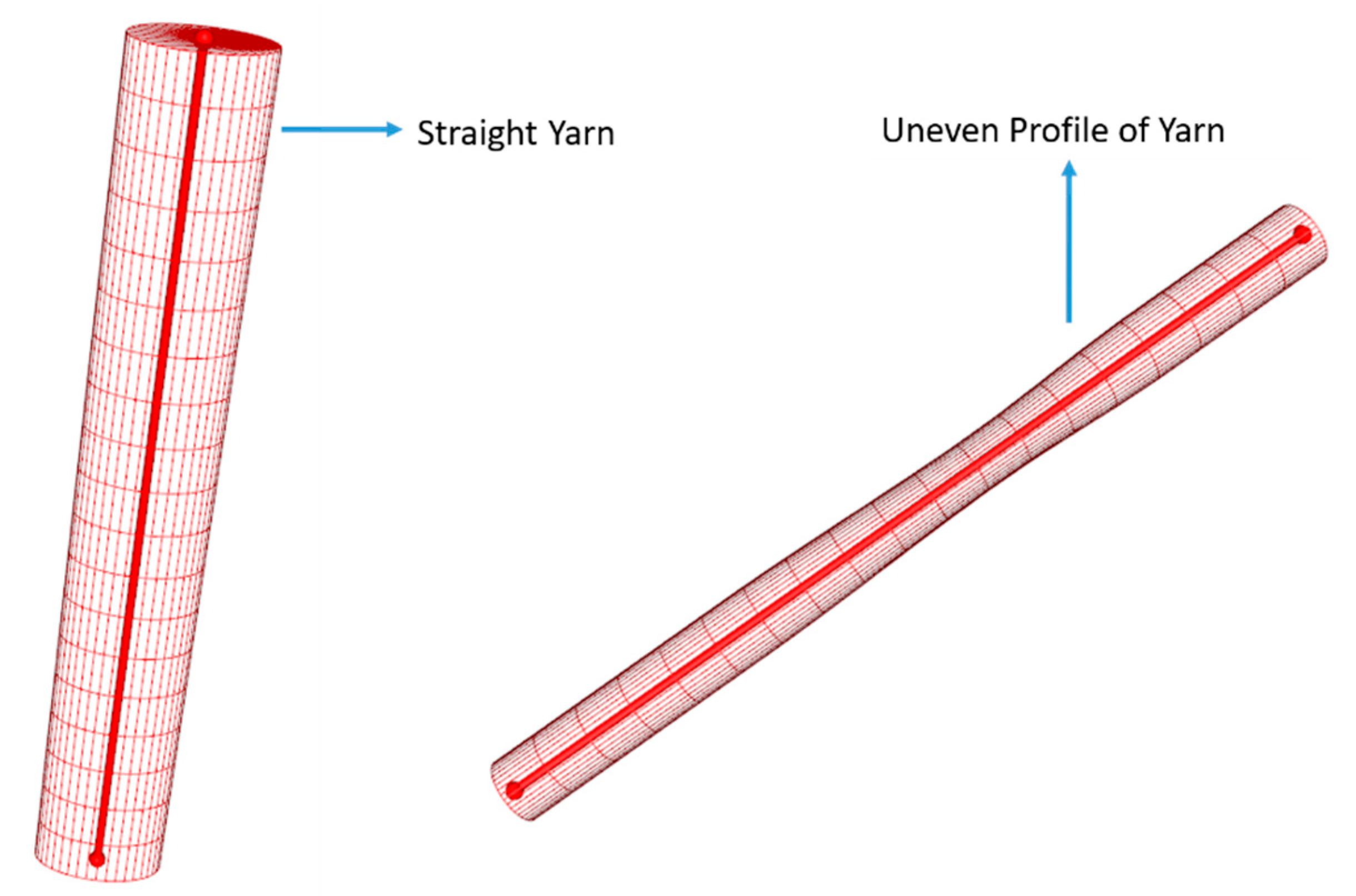
Four-step braiders that belong to cartesian braiding are used for manufacturing 3D four-directional braided composites. In the braiding process, braiding yarns are arranged in rows and columns (m*n), as shown in Figure 2, which generates a 1*1 rectangular pattern [36]. After going through all the four steps, the yarn carrier returns to the original position. There is a jamming action between the yarns during the cycle completion, and it squeezes the yarns, which creates straight and uneven geometry [37].
A total number of yarns (N) in the 1*1 rectangular pattern by rectangular preform can be obtained by Equation (1).
N = m n + m + n
If the cross-section of the unit cell is cut longitudinally with 45° angles from the preform surface, then the orientation angle of yarns is denoted by γ . The relationship between the pitch (h) of 1*1 pattern and orientation angle ( γ ) is:
h tan γ = 8 b
As the yarn’s cross-section is elliptical at perpendicular to its length, hence 2a and 2b are its major and minor axis, respectively. Because of the jamming action, the pitch (hmin) of the braided cell is represented as per the below equation:
h min = 4 b tan γ 2 + tan 2 γ
The interior cell covers the maximum volume fraction of braided composites because of the high number of yarns. Therefore, the interior unit cell model was chosen in this study [1,38]. The unit volume of the rectangular preform (Uy) and the total volume of yarns (Y) in the unit cell are given by
U y = h 3 tan 2 γ
Y = 8 π a b h cos 2 γ
The volume fraction of yarns (Vy) is the ratio of the total yarns’ volume (Y) and unit volume of the preform (Uy) in a braided cell, and fiber volume fraction (Vf) is obtained by multiplying the fiber packing factor ( κ ).
V y = π 8 3
V f = π κ 8 3
Using the shape, size, volume fraction, and the number of yarn data, yarns modeling was carried out through the TexGen python script [39]. For modeling the 3D four-direction braided mesoscale model, firstly, one yarn was modeled. The yarn’s centerline was denoted by several discrete control points making the braiding yarn path in 3D space. Linear interpolation functions coupled these control points. It was assumed that the braiding process is stable, and all yarns undertake the same jamming condition. However, yarns (fiber bundles) become straight and stable after jamming action [40], but an unequal distance between the center lines of the fiber bundles makes them uneven at some locations, presented in Figure 3. When the yarn comes under the straight and stable condition, its cross-sectional tries to turn into elliptical; this was also taken into account while modeling the yarn [36]. Other yarns were modeled to complete the meso-scale braided model at defined positions of the fiber bundles.
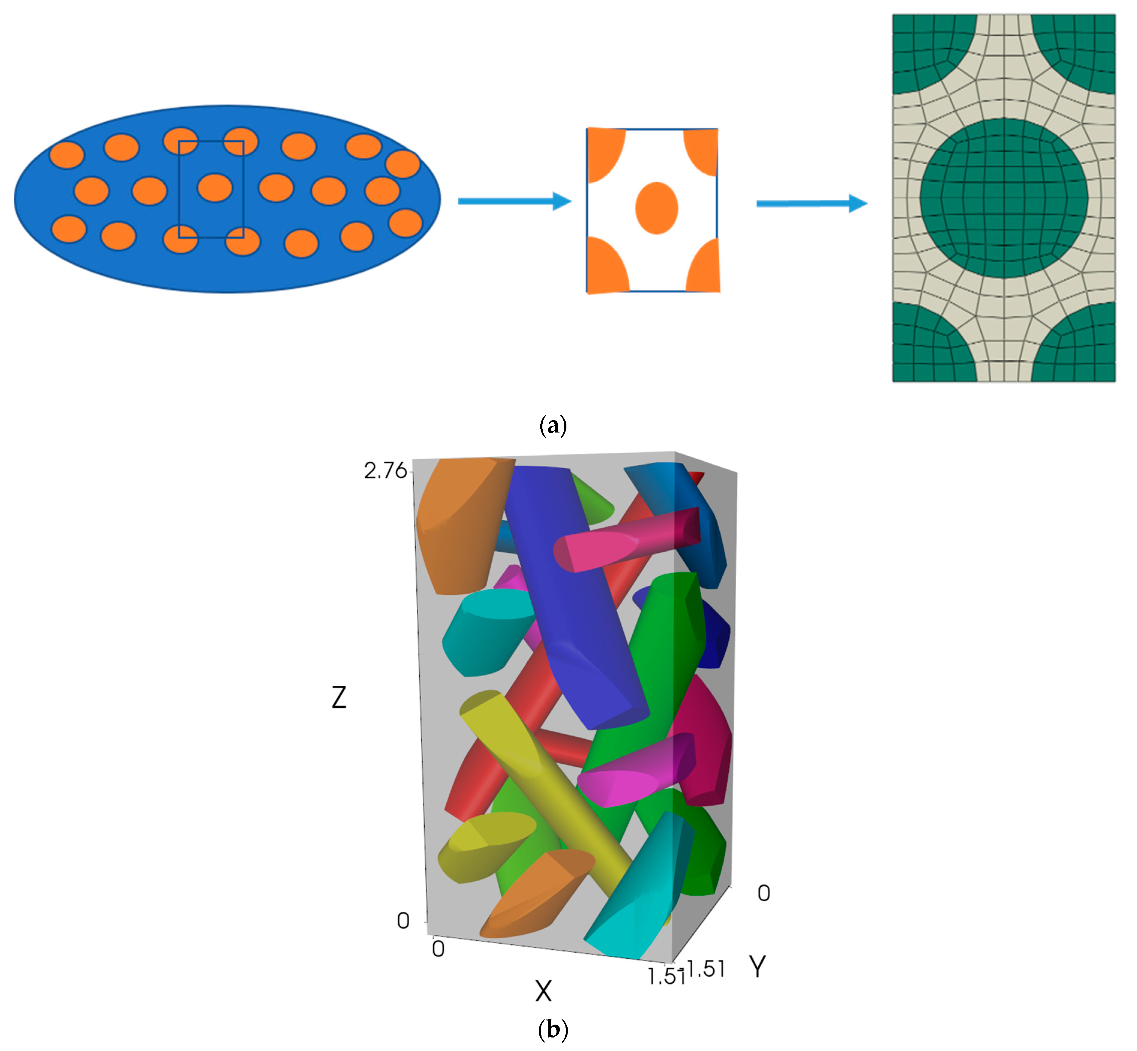
The micro-scale model was made based on the fiber volume fraction (0.52) to capture repetitive fibers in the yarn to get significant yarn properties. Hexagonal packing was modeled to predict repetitive fibers in the yarn accurately, where the fiber volume fraction was assumed to be 0.52 [41]. This model has shown in Figure 4a.
Because of the comparative study, the size of the braided meso-scale model was chosen 1.51*1.51*2.02 (x*y*z) mm as shown in Figure 4b, where the pitch, width (in x, and y directions), and braiding angle are 2.02, 1.51 mm, and 36.6°, respectively [41]. A braided meso-scale 3D model with matrix and yarn trajectory is shown in Figure 4b.
After completing the modeling part, the meso-scale model was exported from TexGen to Abaqus input (.inp) format for the homogenization analysis. A micro-scale model was modeled in the analysis software itself; that is why the meso-scale modeling strategy has been illustrated extensively.

2.2. Homogenization

Based on Hill-Mandel or macro homogeneity condition [42], the homogenization can be interpreted as a finding of a homogeneous material with equivalent strain energy (U) to a given heterogeneous material
U = 1 2 σ i j ε i j = 1 2 σ i j ¯ ε i j ¯ .
On this basis, multi-scale modeling can be done for macro-scale analysis after taking repetitive parts at the micro and meso levels. There are different theories for homogenization, such as RVE (representative volume element) based theory, which is based on average volume and uniform stress field (Reuss) or uniform strain field (Voigt) assumption [14]. Mathematical homogenized theory (MHT, or asymptotic homogenization) works as a two-scale formulation and starts with a variation of the displacement fields in asymptotic series and calculates the stiffness matrix [43].
MSG based theory has an advantage on both periodic as well as aperiodic structures [33]. In MSG, terminology for the basic repetitive unit cell structure is called the structure genome (SG). In this method, the heterogeneous material’s displacement expresses the corresponding homogeneous material and fluctuating functions. Two coordinates at both micro and macro levels are considered in this method. These are x = (x1, x2, x3) for the original heterogeneous structure, and y = (y1, y2, y3) for the micro coordinate system represents the change in the material characteristics in SG [30]. Compared to the macroscopic deformation, SG size is too small, and the term , which is a small parameter, is presented by yi = xi/ .
The minimum energy (strain energy density function) loss is the foundation of this method, which considers that by minimizing the energy loss between the original model and the homogenized model, the homogenized model can be constructed. The difference between the strain energy density function of both models should be near zero. According to MSG, the original model’s kinematics needs to indicate in terms of the homogenized model, then the strain field of the original model is achieved. As a result, effective material properties are obtained as per the Equations (10)–(14) [33,34].
u i ( x , y ) = u i ¯ ( x ) + χ i ( x , y )
where u i and u i ¯ show the displacement field of an original and homogenized model, respectively. χ i is known as the fluctuation function, which is the difference between these fields.
ε i j ( x , y ) = ε i j ¯ ( x ) + 1 δ χ ( i | j )
where χ ( i | j ) denotes the sum of the differentiation with respect to ith and jth values. The difference of strain energy between the original model and the homogenized model is:
π = 1 2 C i j k l ε i j ε k l 1 2 C i j k l ε i j ¯ ε k l ¯ .
To minimize the difference, it is assumed that the homogenized model should not vary, then the fluctuation function (in Equation (10)) can be solved using the following constraints in Equation (12).
χ i = 0 χ ( i , j ) = 0 .
These constraints implicit that homogenized and original models are the same in terms of the average strain and displacement field. MSG minimizes the difference of strain energy between heterogeneous and homogenized models (as in Equation (11)) to utilize the principle of minimum information loss. The fluctuation function χ i (the difference between original and homogenized model field) can be calculated by following Equation (13).
min X i C i j k l ε i j ε k l = min X i E q . ( 12 ) 1 2 C i j k l ( ε i j ¯ + χ ( i , j ) ) ( ε i j ¯ + χ ( k , l ) ) .
The above theory concludes the minimization of the strain energy function of the constitutive model. MSG theory factorizes the equation system and solves six load conditions simultaneously, so it is faster than others [30].
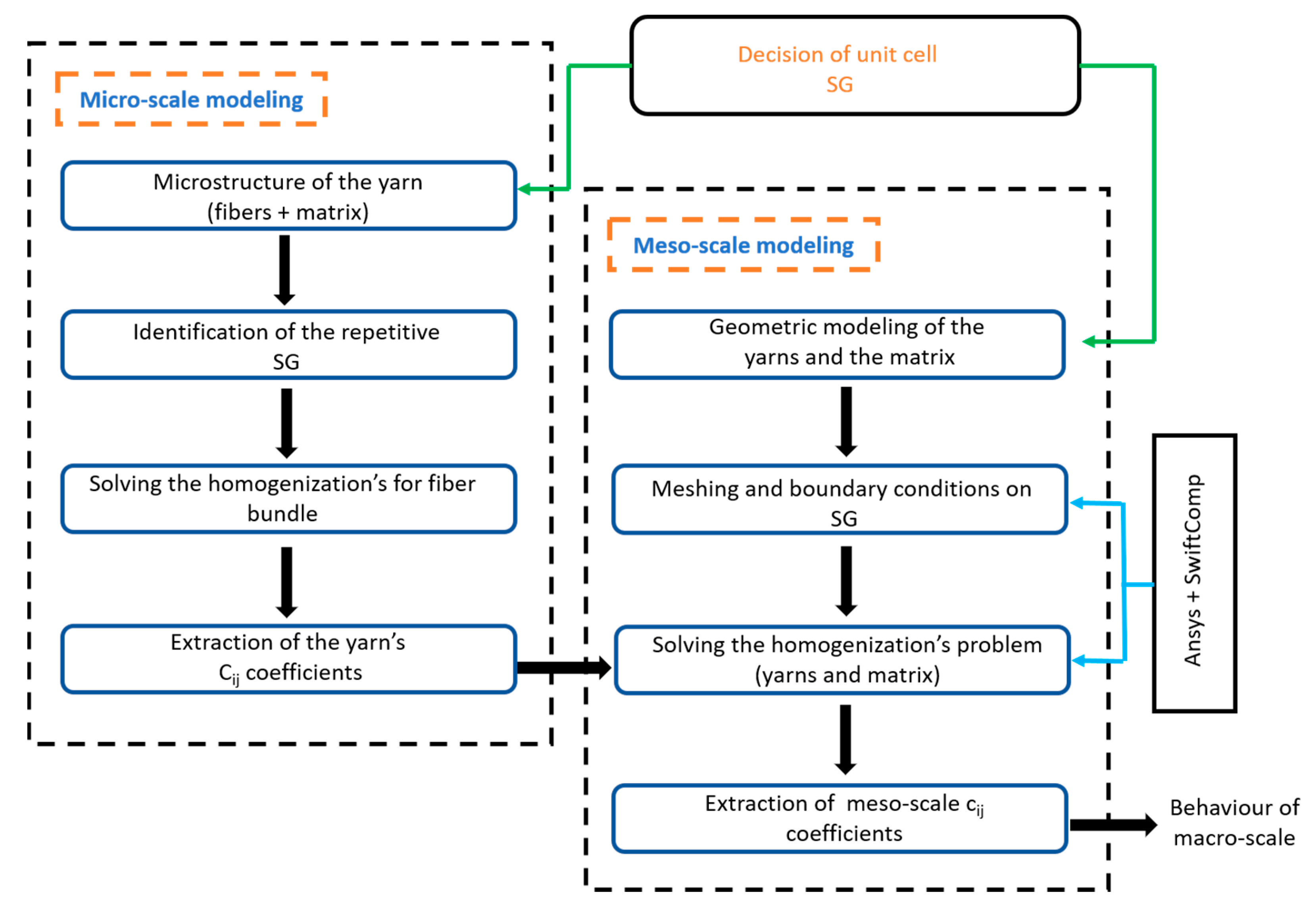
The homogenization process was completed from micro to meso-scale, as shown in Figure 5.

2.2.1. Micro-Scale Homogenization

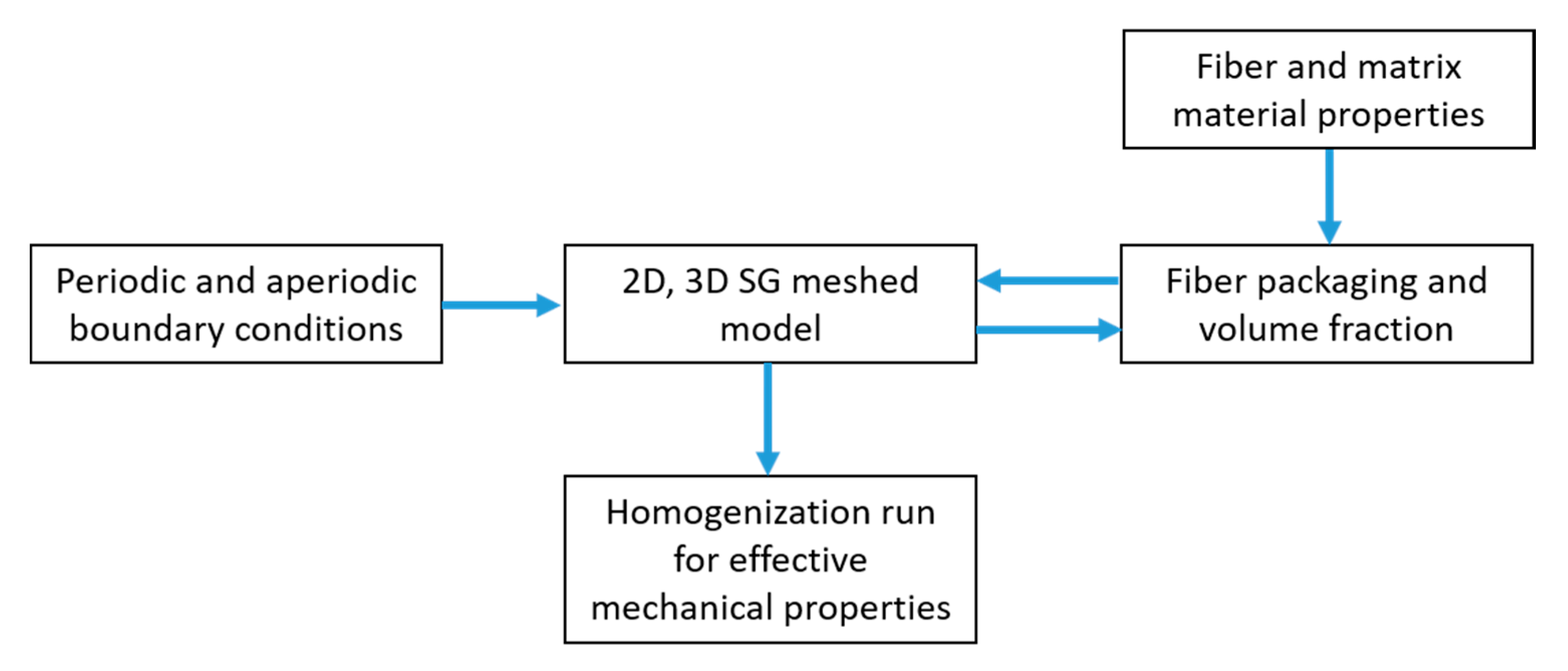
Fibers and matrix constituents form yarns in a 3D braided composite material where fibers were packed and bonded densely with the matrix. In micro-scale homogenization, yarns’ effective material properties could be predicted under the premise of knowing the material properties of fibers and matrix. Fibers and matrix were considered as transversely isotropic and isotropic, respectively. Material properties are shown in Table 1 (1, 2, and 3 shown for x, y, and z directions, respectively) [44]. The process of the micro-scale homogenization is described in Figure 6. The micro-scale model meshed with 1992 elements and 2085 nodes with periodic boundary conditions. Effective yarn properties were calculated based on the MSG. The benefit of MSG is that it can calculate the effective 3D stiffness properties by 2D SG as the strain energy of 2D SG can be expressed by the 3D strain field [34]. Obtained effective yarn properties (Table 1) will be used for the meso-scale homogenization to estimate the behavior of the macro-scale structure of braided composites.

2.2.2. Meso-Scale Homogenization

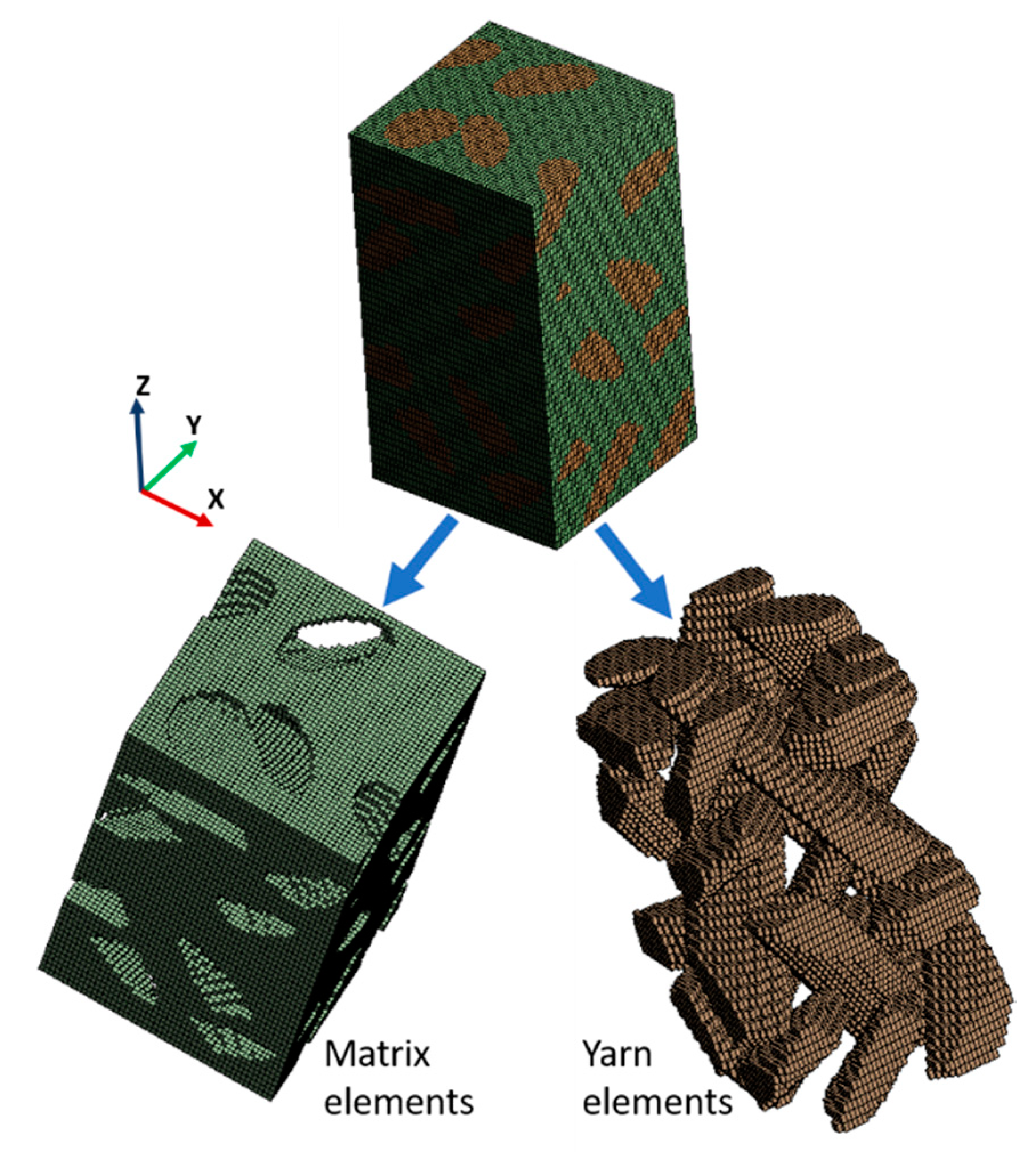
The meso-scale model with yarns and matrix could be captured by following the previously mentioned braiding technique, as shown in Figure 4b. The meso-scale model was exported with voxel mesh, eight-node bilinear reduced integration C38DR solid elements in the Abaqus input (.inp) format. This file was imported into Ansys software as an external model. The number of elements and nodes in the meshed model is 125000 and 13265, respectively, as shown in Figure 7. The material properties of the resin matrix and yarns (calculated from micro-scale homogenization) are shown in Table 2. The boundary conditions and load conditions were defined in the Ansys-SwiftComp [45]. Boundary conditions were incorporated as a constraint equation on corresponding surfaces at each node. It was done by applying constrained (tied to the opposite surfaces) on corresponding face’s nodes (periodic conditions) of meso-scale meshed model (shown in Figure 7). For controlling aperiodicity, the MSG has the benefit of making aperiodic boundary conditions in the selected direction. It can be done by choosing aperiodicity in the analysis step, like a traction free boundary condition because of no periodicity. Overall, load and boundary conditions were inbuilt characteristics of SwitComp (MSG), which were analyzed and completed by Ansys GUI because MSG is a semi-analytical method. Finally, homogenization based on MSG was performed to get effective homogenized mechanical properties (Table 2).

2.2.3. Effective Mechanical Properties for Braided Ceramic Matrix Composites (C/SiC)

After verifying the properties for four-directional braided PMCs, the same two-step homogenization was applied on braided CMCs to extend and check the versatility of the current multi-scale homogenization process. Homogenizations were conducted with the same conditions, like the number of elements, nodes, boundary, and load conditions, as presented above for the PMCs case. The fiber and matrix used in this study were carbon (T300) and silicon carbide, respectively. The mechanical properties of carbon fiber (T300) are listed in Table 1. Young’s modulus and Poisson’s ratio for silicon carbide (matrix) were considered 420 GPa and 0.2, respectively [46,47]. The matrix properties were taken at room temperature, with no interphase and defects, and assumed fully bonded without cracks. The effective properties of yarns were calculated by MSG based micro-scale homogenization. The same meso-scale model (as shown in Figure 4b) was used for the meso-scale homogenization with yarn (from micro-scale CMCs homogenization) and matrix properties to get final effective mechanical properties for 3D four-directional braided CMCs. After two scale homogenization obtained mechanical properties are E11 = 213.522 GPa, E22 = 195.171 GPa, E33 = 277.613 GPa, G12 = 214.323 GPa, G13 = 283.321 GPa, G23 = 281.305 GPa, ν12 = 0.260, ν13 = 0.341, ν23 = 0.347.

2.3. Finite Element Analysis (Numerical Analysis) at the Meso-Scale

FEA was conducted for 3D four-directional braided composites at the meso-scale [27,48]. It was done to cross-check the homogenization results. Numerical analysis was performed by six displacement and symmetry boundary conditions to get material properties. The boundary conditions can be traction, displacement, or mixed (traction and displacement) [49,50].
The relationship between stress ( σ ) and strain ( ε ) with a fourth-order tensor (compliance) matrix ( S ) is expressed by the below equations.
ε = S σ
[ ε 11 ε 22 ε 33 γ 23 γ 13 γ 12 ] = ( S 11 S 12 S 13 S 14 S 15 S 16 S 21 S 22 S 23 S 24 S 25 S 26 S 31 S 32 S 33 S 34 S 35 S 36 S 41 S 42 S 43 S 44 S 45 S 46 S 51 S 52 S 53 S 54 S 55 S 56 S 61 S 62 S 63 S 64 S 65 S 66 ) [ σ 11 σ 22 σ 33 τ 23 τ 13 τ 12 ]
[ ε 11 ε 22 ε 33 γ 23 γ 13 γ 12 ] = ( 1 E 11 υ 21 E 22 υ 31 E 33 0 0 0 υ 12 E 11 1 E 22 υ 32 E 33 0 0 0 υ 13 E 11 υ 23 E 22 1 E 33 0 0 0 0 0 0 1 G 23 S 45 0 0 0 0 0 1 G 13 0 0 0 0 0 0 1 G 12 ) [ σ 11 σ 22 σ 33 τ 23 τ 13 τ 12 ]
The FEA was performed as per the following steps:
(i) The meso-scale braided model’s geometry (Figure 4b) was imported in Ansys 2019 R2. (ii) The same material properties were assigned for yarns (fiber bundles) and matrix (SiC), used in the current homogenization process. (iii) Meshing was completed with tetrahedral elements, and meshing quality was also checked for better prediction [51]. The elements and nodes corresponding to the meshed model were 389421 and 534731, respectively, with an element size of 0.05 mm. The element orientation of fiber bundles and the matrix is essential to control heterogeneity. (iv) Fibers and matrix parts were chosen to assign local orientation for controlling their material directions. (v) Displacement boundary conditions were applied for six different cases. It is necessary to choose and apply exact symmetry for every case (six) to maintain boundary conditions for pure tension and shear, as shown in Table 3. After applying all conditions for each case, it was achieved that: E 11 = σ 11 ε 11 , E 22 = σ 22 ε 22 , E 33 = σ 33 ε 33 , G 12 = τ 12 γ 12 , G 13 = τ 13 γ 13 , G 23 = τ 23 γ 23 , νij = ε jj ε ii (i, j = 1,2,3), where 1, 2, and 3 show x, y, and z directions, respectively. Boundary conditions managed that applying displacement in the x-direction would give E11 and the same for E22, E33, G12, G13, and G23 for directional (y and z) tension and shear.
After completing the analysis, it must be checked that the applied boundary conditions are correct in pure tension or shear with the respective directions for reliable results. Figure 8 shows the pure tension and shear with deformed and undeformed shapes after the simulation, indicates that the applied boundary conditions in the analysis were accurate. Then postprocessing was performed to get elastic modulus and Poisson’s ratio, as shown in Figure 9. Final calculated properties from FEA are E11 = 214.321 GPa, E22 = 197.153 GPa, E33 = 278.215 GPa, G12 = 214.352 GPa, G13 = 285.413 GPa, G23 = 282.315 GPa, ν12 = 0.262, ν13 = 0.342, ν23 = 0.349.

3. Discussion and Validation

In the previous section, modeling, analysis, and calculation results are presented. In this section mainly, validation of the calculated results is covered. This research extended the MSG technique for 3D four-directional braided composites. Multi-scale modeling and homogenization by MSG method have a versatile capability to make time saving and trustworthy environment. The two-step homogenization requires a well-defined model on both stages. In the previous section of this paper, the mechanical properties of PMCs were calculated using two step modeling and homogenization by MSG because of the available literature for four-directional braided PMCs (T300/Epoxy resin) from other methods, so that verification of the presented method was done. The modeling methodology needs only fiber arrangement and volume fraction in yarn for the first stage of homogenization. With hexagonal packing of fiber, a micro-scale model was generated. Then the first scale homogenization analysis was finished. Micro-scale homogenization results were verified with empirical formulae based on the existing results, and the relative error in y and z-direction is 0.23% [41]. After ensuring the results from the first scale homogenization for yarns, it can be said that method has got relevant results to move towards the second step. Then, Yarn’s effective mechanical properties from the microscale model were used for the second step homogenization. Below, Equation (17) shows the error calculation during validation with the literature results.
e r r o r % = ( Current literature   or   experimental )   results 100 Literature   or   experimental   results
The meso-scale model was prepared with all process details using TexGen python scripts because fiber arrangements were four-directional, and modeling is complex to not generate in analysis software itself. The second step homogenization was processed with meso-scale model and fiber bundles (yarns) properties (from first step analysis). Matrix properties were the same in both scale analysis. As a result, effective mechanical properties of the 3D four-directional braided composites were obtained. The obtained final results were compared with previous 3D four-directional composites (PMCs) results, as shown in Table 4.
From the comparison, it is observed that the current homogenization results are closed to the existing literature. These existing literature results are based on other methods like FEM and experiments. While comparing the tensile modulus in the z-direction, the relative error of currently obtained results with FEM based literature results is 3.21% [41]. This error is only 0.5% when compared with the experiment based literature [44]. The current method and previously presented results have compared with experimental literature results, which shows that current predicted results have less relative error (0.5%) compared to existing FEM literature (3.59%) results. This comparison indicates that the present process is well efficient for 3D four-directional braided composites. It needs to apply on different common composites for checking versatility; that is why it was extended for 3D four-directional braided CMCs (T300/SiC). The current technique also generated four-directional braided CMCs mechanical properties. FEA was conducted to certify the current homogenization process results’ adaptability due to a lack of literature for the 3D four-directional braided CMCs model.
In comparison, obtained mechanical properties from FEA and the current homogenization process are closely matched for four-directional braided CMCs, as shown in Table 5 (row 2 and 3 shows two-step MSG and FEM based results, respectively). The error between FEA and homogenization process results (Table 5) in the z-direction is 0.22%. The current results and other method’s literature results are presented in Table 4 and Table 5, which shows results are well qualified in all directions and fair accuracy of the current method. The comparison is mostly discussed with z-direction for validation because there is the availability of experimental literature in z-direction for four-direction braided composites, as shown in Table 4. Also another reason is that braided composites mainly improve transverse strength as well as shear strength. The assumption was made that the matrix was fully bonded with fibers in first-scale homogenization. Even interference was covered in first-scale homogenization, but in the second step homogenization, matrix, and fibers bundles were taken fully bonded.
In the future, this process will also incorporate loosely bonded composites to calculate mechanical properties because, generally, bond imperfection is possible during the composite manufacturing process. This research methodology can also use to predict mechanical properties for any kind of composite structure.

4. Conclusions

An effective, fast modeling, and analysis approach was explored to estimate 3D four-directional braided composites’ mechanical material properties. Multi-scale modeling and homogenization by MSG theory were identified to provide efficient results for four-directional braided composites. It was analyzed that the selection and building of repetitive unit cell models with exact observation and dimension calculations are necessary for the multi-scale modeling. Jamming action was considered for meso-scale modeling to keep the braiding process in mind. The current homogenization process was verified for braided composites on applying PMCs material, and results compared with the other existing methods. It was also employed to predict the mechanical properties of braided CMCs (C/SiC). Numerical analysis (FEA) was performed at the meso-level for verification. It was found that the element orientation controls the heterogeneity, and proper symmetry and displacement boundary conditions make true to pure tension and shear situations in FEA. It is concluded that the homogenization process (MSG) is faster than others (RVE, FEA) for four-directional braided composites to predict the mechanical material properties. This research opens a new way to model and analyze 3D braided four-directional composites faster and accurately. Main findings are:
  • Modeling requires manufacturing process effects such as braiding patterns and jamming conditions.
  • MSG is a robust and versatile technique for the mechanical characterization of braided composite materials.
  • Four-directional braided composites have high shear and transverse modulus.
  • FEA is time-consuming than MSG, and while doing FEA, proper boundary and load condition is needed with exact symmetry in composite materials.

Author Contributions

Three authors are belonging. Software, methodology, analysis, validation, and writing original draft was carried out by V.K.D., writing, review, editing, and visualization were completed by Y.C., Investigation, supervision, project administration, and funding acquisition were done by C.C. All authors have read and agreed to the published version of the manuscript.

Funding

This research was supported under the international cooperation program framework managed by the National Research Foundation of Korea (Grant Number: NRF-2018K2A9A2A06023082).

Conflicts of Interest

The authors declare that there is no conflict of interest.

Nomenclature

C i j k l Fourth-order tensor 6 × 6 stiffness matrix
C i j k l Corresponding stiffness for the homogenized model
UThe average strain energy of a unit cell
σ i j Stress field for heterogeneous body
ε i j Strain field for heterogeneous body
σ ij ¯ Stress field for homogeneous body
ε i j ¯ Strain field for homogeneous body
U y Unit volume of rectangular preform
h Pitch of a unit cell
κ Fiber packing fraction
δ A small parameter to describe the structure genome
π Difference in energy
. Volume average
νPoisson ratio
EYoung’s modulus
GShear modulus
MSGMechanics of structure genome
NNumber of yarns
m and nNumber of rows and columns
γ The orientation angle of the yarn
hPitch of the unit cell (1*1 rectangular pattern)
2a and 2bYarn cross section’s major and minor axis
UyThe unit volume of the rectangular preform
YThe total volume of yarns
VyThe volume fraction of yarns
VfFiber volume fraction
κFiber packing factor

References

  1. Gu, Q.; Quan, Z.; Yu, J.; Yan, J.; Sun, B.; Xu, G. Structural modeling and mechanical characterizing of three-dimensional four-step braided composites: A review. Compos. Struct. 2019, 207, 119–128. [Google Scholar] [CrossRef]
  2. Tang, S.; Hu, C. Design, Preparation and Properties of Carbon Fiber Reinforced Ultra-High Temperature Ceramic Composites for Aerospace Applications: A Review. J. Mater. Sci. Technol. 2017, 33, 117–130. [Google Scholar] [CrossRef]
  3. Ko, F. Tensile Strength and Modulus of a Three-Dimensional Braid Composite. Available online: https://www.astm.org/DIGITAL_LIBRARY/STP/PAGES/STP35359S.htm (accessed on 26 November 2020).
  4. Ma, C.-L.; Yang, J.-M.; Chou, T.-W. Elastic Stiffness of Three-Dimensional Braided Textile Structural. Available online: https://www.astm.org/DIGITAL_LIBRARY/STP/PAGES/STP35360S.htm (accessed on 26 November 2020).
  5. Yang, J.-M.; Ma, C.-L.; Chou, T.-W. Fiber Inclination Model of Three-Dimensional Textile Structural Composites. J. Compos. Mater. 1986, 20, 472–484. [Google Scholar] [CrossRef]
  6. Kalidindi, S.R.; Franco, E. Numerical evaluation of isostrain and weighted-average models for elastic moduli of three-dimensional composites. Compos. Sci. Technol. 1997, 57, 293–305. [Google Scholar] [CrossRef]
  7. Jiang, L.; Zeng, T.; Yan, S.; Fang, D. Theoretical prediction on the mechanical properties of 3D braided composites using a helix geometry model. Compos. Struct. 2013, 100, 511–516. [Google Scholar] [CrossRef]
  8. Wu, D.L.; Hao, Z.P. 5D Braided Structural Composites. J. Astronaut. 1993, 3, 13–16. [Google Scholar]
  9. Wu, D. Three-cell model and 5D braided structural composites. Compos. Sci. Technol. 1996, 56, 225–233. [Google Scholar] [CrossRef]
  10. Wang, Y.Q.; Zhang, L.T.; Cheng, L.F. Computer geometry simulation of spatial structure of three-dimensional braided composites. J. Aeronaut. Mater. 2008, 28, 95–98. [Google Scholar]
  11. Chen, L.; Tao, X.-M.; Choy, C. Mechanical analysis of 3-D braided composites by the finite multiphase element method. Compos. Sci. Technol. 1999, 59, 2383–2391. [Google Scholar] [CrossRef]
  12. Verpoest, I.; Lomov, S.V. Virtual textile composites software WiseTex: Integration with micro-mechanical, permeability and structural analysis. Compos. Sci. Technol. 2005, 65, 2563–2574. [Google Scholar] [CrossRef]
  13. Nottingham, T. Geometric and Mechanical Modelling of Textiles. Ph.D. Thesis, University of Nottingham, Nottingham, UK, October 2007. [Google Scholar]
  14. Zhang, L.; Hu, D.; Wang, R.; Zeng, Y.; Cho, C. Establishing RVE model composed of dry fibers and matrix for 3D four-directional braided composites. J. Compos. Mater. 2019, 53, 1917–1931. [Google Scholar] [CrossRef]
  15. Wang, Q.; Zhang, R.; Wang, J.; Jiao, Y.; Yang, X.; Ma, M. An Efficient Method for Geometric Modeling of 3D Braided Composites. J. Eng. Fibers Fabr. 2016, 11, 76–87. [Google Scholar] [CrossRef] [Green Version]
  16. Hao, W.; Liu, Y.; Huang, X.; Liu, Y.; Zhu, J. A Unit-Cell Model for Predicting the Elastic Constants of 3D Four Directional Cylindrical Braided Composite Shafts. Appl. Compos. Mater. 2017, 25, 619–633. [Google Scholar] [CrossRef]
  17. Wang, Y.-B.; Liu, Z.-G.; Liu, N.; Hu, L.; Wei, Y.-C.; Ou, J.-J. A new geometric modelling approach for 3D braided tubular composites base on Free Form Deformation. Compos. Struct. 2016, 136, 75–85. [Google Scholar] [CrossRef]
  18. Feng, W.; Wang, Y.R.; Wei, D.S. Meso-scale modeling of 3-D four-directional braided composites. J. Aerosp. Power. 2013, 28, 1243–1249. [Google Scholar]
  19. Li, D.-S.; Li, J.-L.; Chen, L.; Lu, Z.-X.; Fang, D.-N. Finite Element Analysis of Mechanical Properties of 3D Four-Directional Rectangular Braided Composites Part 1: Microgeometry and 3D Finite Element Model. Appl. Compos. Mater. 2010, 17, 373–387. [Google Scholar] [CrossRef]
  20. Mirzavand, B.; Pourmohammad, H. Post-buckling analysis of non-uniformly heated functionally graded cylindrical shells enhanced by shape memory alloys using classical lamination theory. J. Intell. Mater. Syst. Struct. 2019, 30, 2421–2435. [Google Scholar] [CrossRef]
  21. Nagai, K.; Yokoyama, A.; Maekawa, Z.; Hamada, H. The study of analytical method for three-dimensional composite materials. Trans. Japan Soc. Mech. Eng. 1992, 58, 2099–2103. [Google Scholar] [CrossRef] [Green Version]
  22. Wang, Y.-Q.; Wang, A. Microstructure/property relationships in three-dimensionally braided fiber composites. Compos. Sci. Technol. 1995, 53, 213–222. [Google Scholar] [CrossRef]
  23. Gowayed, Y.A.; Pastore, C.M. Analytical techniques for the prediction of elastic properties of textile reinforced composites. Mech. Compos. Mater. 1993, 28, 393–408. [Google Scholar] [CrossRef]
  24. Wang, C.; Cao, P.; Tang, M.; Wang, C.; Liu, K.; Liu, B. Study on Properties Prediction and Braiding Optimization of Axial Braided Carbon/Carbon Composite. Materials 2020, 13, 2588. [Google Scholar] [CrossRef] [PubMed]
  25. Katouzian, M.; Vlase, S. Mori–Tanaka Formalism-Based Method Used to Estimate the Viscoelastic Parameters of Laminated Composites. Polymers 2020, 12, 2481. [Google Scholar] [CrossRef] [PubMed]
  26. Chen, H.; Baird, D. Prediction of Young’s Modulus for Injection Molded Long Fiber Reinforced Thermoplastics. J. Compos. Sci. 2018, 2, 47. [Google Scholar] [CrossRef] [Green Version]
  27. Bednarcyk, B.A.; Mital, S.K.; Pineda, E.J.; Arnold, S.M. Multiscale Modeling of Ceramic Matrix Composites. In Proceedings of the 56th AIAA/ASCE/AHS/ASC Structures, Structural Dynamics, and Materials Conference, Kissimmee, FL, USA, 5–9 January 2015. [Google Scholar]
  28. Singh, D.K.; Vaidya, A.; Thomas, V.; Theodore, M.; Kore, S.; Vaidya, U. Finite Element Modeling of the Fiber-Matrix Interface in Polymer Composites. J. Compos. Sci. 2020, 4, 58. [Google Scholar] [CrossRef]
  29. Dodla, S. Micromechanical Analysis for Two-Phase Copper-Silver Composites under Large Deformations. J. Compos. Sci. 2018, 2, 1. [Google Scholar] [CrossRef] [Green Version]
  30. Yu, W. Simplified Formulation of Mechanics of Structure Genome. AIAA J. 2019, 57, 4201–4209. [Google Scholar] [CrossRef]
  31. Miehe, C.; Schröder, J.; Becker, M. Computational homogenization analysis in finite elasticity: Material and structural instabilities on the micro- and macro-scales of periodic composites and their interaction. Comput. Methods Appl. Mech. Eng. 2002, 191, 4971–5005. [Google Scholar] [CrossRef]
  32. Kassapoglou, C.; Lagace, P.A. An Efficient Method for the Calculation of Interlaminar Stresses in Composite Materials. J. Appl. Mech. 1986, 53, 744–750. [Google Scholar] [CrossRef]
  33. Peng, B.; Yu, W. A micromechanics theory for homogenization and dehomogenization of aperiodic heterogeneous materials. Compos. Struct. 2018, 199, 53–62. [Google Scholar] [CrossRef]
  34. Liu, X.; Rouf, K.; Peng, B.; Yu, W. Two-step homogenization of textile composites using mechanics of structure genome. Compos. Struct. 2017, 171, 252–262. [Google Scholar] [CrossRef]
  35. Rouf, K.; Liu, X.; Yu, W. Multiscale structural analysis of textile composites using mechanics of structure genome. Int. J. Solids Struct. 2018, 136–137, 89–102. [Google Scholar] [CrossRef]
  36. Tan, H.; Liu, L.; Guan, Y.; Chen, W.; Zhao, Z. Investigation of three-dimensional braided composites subjected to steel projectile impact: Automatically modelling mesoscale finite element model. Compos. Struct. 2019, 209, 317–327. [Google Scholar] [CrossRef]
  37. Bilisik, K. Three-dimensional braiding for composites: A review. Text. Res. J. 2015, 83, 1414–1436. [Google Scholar] [CrossRef]
  38. Wang, R.; Zhang, L.; Hu, D.; Shen, X.; Song, J. Mesoscopic modeling of 3D four-directional braided composites. In Proceedings of the ASME Turbo Expo (Vol. 6); American Society of Mechanical Engineers (ASME): Seoul, Korea, 2016. [Google Scholar]
  39. Long, A.C.; Brown, L.P. Modelling the geometry of textile reinforcements for composites: TexGen. In Composite Reinforcements for Optimum Performance; Woodhead Publishing: Sawston, UK, 2011; pp. 239–264. [Google Scholar]
  40. Hu, L.; Tao, G.; Liu, Z.; Wang, Y.; Ya, J. Investigation on the Yarn Squeezing Effect of Three Dimensional Full Five Directional Braided Composites. Appl. Compos. Mater. 2019, 26, 371–387. [Google Scholar] [CrossRef]
  41. Wang, R.; Zhang, L.; Hu, D.; Liu, C.; Shen, X.; Cho, C.; Li, B. A novel approach to impose periodic boundary condition on braided composite RVE model based on RPIM. Compos. Struct. 2017, 163, 77–88. [Google Scholar] [CrossRef]
  42. Qu, J.; Cherkaoui, M. Fundamentals of Micromechanics of Solidss; John Wiley and Sons: Hoboken, NJ, USA, 2007. [Google Scholar]
  43. Kalamkarov, A.L. Asymptotic homogenization method and micromechanical models for composite materials and thin-walled composite structures. In Mathematical Methods and Models in Composites; World Scientific: Singapore, 2013. [Google Scholar]
  44. Xiu, Y. Numerical Analysis of Mechanical Properties of 3D Four-Step Braided Composites. Master’s Thesis, Tianjin Polytechnic University, Tianjin, China, 2001. [Google Scholar]
  45. Tian, S.; Yu, W.; Liu, X.; Sertse, H. Ansys Workbench Swiftcomp gui User Manual. Available online: https://cdmhub.org/groups/yugroup/resources?id=1726 (accessed on 26 November 2020).
  46. Liu, K.C.; Arnold, S.M. Influence of scale specific features on the progressive damage of woven ceramic matrix composites (CMCs). Comput. Mater. Contin. 2013, 35, 35–65. [Google Scholar]
  47. Murthy, P.L.N.; Sullivan, R.M.; Mital, S.K. Modeling of 3-D Woven Ceramic Matrix Composites. Available online: https://ntrs.nasa.gov/citations/20030020624 (accessed on 26 November 2020).
  48. Yu, G.; Shi, B.; Shen, Y.; Gu, J. A novel finite element method for predicting the tensile properties of 3D braided composites. Mater. Res. Express 2019, 6, 125626. [Google Scholar] [CrossRef]
  49. Liu, G.R.; Quek, S.S. Briefing on mechanics for solids and structures. In The Finite Element Method, 2nd ed.; Elsevier Ltd.: Amsterdam, The Netherlands, 2014; pp. 13–41. [Google Scholar]
  50. Aboudi, J.; Arnold, S.M.; Bednarcyk, B.A. Fundamentals of the Mechanics of Multiphase Materials. In Micromechanics of Composite Materials; Elsevier Inc.: Amsterdam, The Netherlands, 2013; pp. 87–145. [Google Scholar]
  51. Guo, Q.; Zhang, G.; Li, J. Process parameters design of a three-dimensional and five-directional braided composite joint based on finite element analysis. Mater. Des. 2013, 46, 291–300. [Google Scholar] [CrossRef]
Figure 1. Multi-scale modeling (macro, meso, and micro-scale).
Jcs 04 00179 g001
Figure 2. Steps to generate a 1*1 rectangular pattern.
Jcs 04 00179 g002
Figure 3. Profiles of yarn.
Jcs 04 00179 g003
Figure 4. (a) Micro-scale model with fiber and matrix; (b) meso-scale model with yarn trajectory and matrix (transparent).
Jcs 04 00179 g004
Figure 5. Two-step homogenization process.
Jcs 04 00179 g005
Figure 6. Micro-scale homogenization (First step).
Jcs 04 00179 g006
Figure 7. Meso-scale meshed model.
Jcs 04 00179 g007
Figure 8. Conditions after analysis, (a) pure tension in z; (b) pure shear in zy plane; (c) pure tension in x; and (d) pure shear in the xy plane.
Jcs 04 00179 g008
Figure 9. Stress in the finite element model (a) stress under pure z tension-composite model, matrix and yarns (fiber bundles); (b) stress under pure x tension-composite model, matrix and yarns (fiber bundles); and (c) stress under pure xy shear-composite model, matrix and yarns (fiber bundles).
Jcs 04 00179 g009
Table 1. Calculated mechanical properties of the constituents (matrix and fibers) and composites (micro-scale).
Material ConstituentsMechanical Properties (GPa)
Matrix (epoxy resin)E = 3.5, ν = 0.35
Fiber (T300 fiber)E11 = 230, E22 = E33 = 40, G12 = G13 = 24, G23 = 14.3, ν1213 = 0.27, ν23 = 0.35
Yarn (fiber bundle if fiber volume fraction is 0.52) properties from micro-scale homogenizationsE11=196.07 GPa, E22 = E33 = 22.10 GPa, G12 = G13 = 10.15 GPa, G23 = 8.07 GPa, ν12 = ν13= 0.27, ν23 = 0.36.
Table 2. Calculated mechanical properties of the braided polymer matrix composites (PMCs) with its constituents (Matrix and Yarn).
Material ConstituentsMechanical Properties
MatrixE = 3.5 GPa, ν = 0.35
YarnE11 = 196.07 GPa, E22 = E33 = 22.10 GPa, G12 = G13 = 10.15 GPa, G23= 8.07 GPa, ν12 = ν13= 0.27, ν23=0.36
Calculated effective homogenized properties of the meso-scale 3D four-dimensional braided PMCs (epoxy resin/T300 carbon fiber) modelE11 = 10.712 GPa, E22 = 10.673 GPa, E33 = 17.821 GPa, G12 = 11.641 GPa, G13 = 18.152 GPa, G23 = 18.112 GPa, ν12 = 0.270, ν13 = 0.370, ν23 = 0.369.
Table 3. Finite element analysis (FEA) boundary conditions for respective elastic constants.
X-AxisY-AxisZ-Axis
(+) Direction (Plane)(-) Direction(+) Direction(-) Direction(+) Direction(-) Direction
E11, ν12Ux = DBAll is fixSym
Uy, Rz, Rx =0
SameSym
Uz, Ry, Rx =0
Same
E22, ν23Sym
Ux, Rz, Ry = 0
SameUy = DBAll is fixSym
Uz, Ry, Rx = 0
Same
E33, ν13Sym
Ux, Rz, Ry = 0
SameSym
Uy, Rz, Rx = 0
SameUz = DBAll is fix
G12Uy = DB, Uz = 0Uy, Uz = 0Ux, Uz = 0Ux, Uz = 0Uz = 0Uz = 0
G13Uz = DB, Uy = 0Uy, Uz = 0Uy = 0Uy = 0Ux, Uy = 0Ux, Uy = 0
G23Ux = 0Ux = 0Ux, Uz = 0Ux, Uz = 0Uy = DB, Ux = 0Ux, Uy = 0
Note: DB = displacement boundary condition, Sym = symmetry.
Table 4. Current results with existing literature results for PMCs (epoxy resin/T300 carbon fiber).
Elastic ConstantsCurrent Process
Results
Literature FEM Results [41]Literature (Experiment) [44]
E11 (GPa)10.71210.645
E22 (GPa)10.67310.651
E33 (GPa)17.82117.26617.91
G12 (GPa)11.74111.607
G13 (GPa)18.55218.145
G23 (GPa)18.53218.138
ν120.2700.269
ν130.3690.371
ν230.3700.371
Table 5. Calculated material Properties for 3D four-directional braided ceramic matrix composites (CMCs) (silicon carbide/T300 carbon fiber).
Analysis ScaleMechanical Properties
Micro-scale homogenization for yarnE11 = 258.537 GPa, E22 = E33 = 58.593 GPa, G12 = G13 = 36.201 GPa, G23 = 28.098 GPa, ν12 = ν13 = 0.23, ν23 = 0.35
Meso-scale homogenization (for macro-model)E11 = 213.522 GPa, E22 = 195.171 GPa, E33 = 277.613 GPa, G12 = 214.323 GPa, G13 = 283.321 GPa, G23 = 281.305 GPa, ν12 = 0.260, ν13 = 0.341, ν23 = 0.347.
FEM resultsE11 = 214.321 GPa, E22 = 197.153 GPa, E33 = 278.215 GPa, G12 = 214.352 GPa, G13 = 285.413 GPa, G23 = 282.315 GPa, ν12 = 0.262, ν13 = 0.342, ν23 = 0.349.
Publisher’s Note: MDPI stays neutral with regard to jurisdictional claims in published maps and institutional affiliations.