
The Factors That Affect the Expansion of the Tape for It to Avoid Side Effects in the Production of Composites in Online LATP Technology

Abstract
:1. Introduction
2. Experimental Details
2.1. Materials and Methods
- UD prepreg material LM-PAEK Toray TC1225 Cetex®/T700
- UD prepreg material PEKK/CF Ten Cate TC1320/AS4
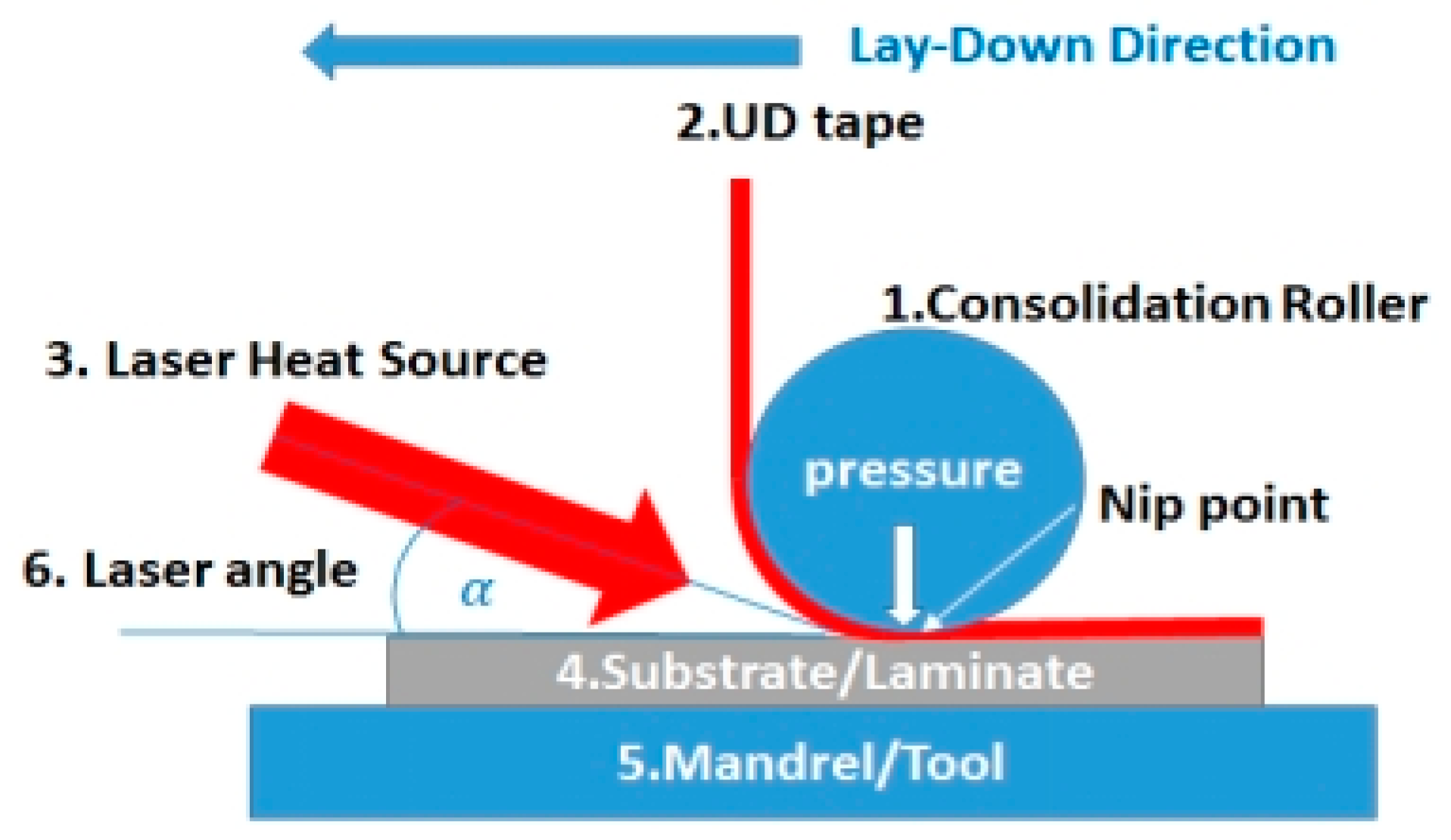
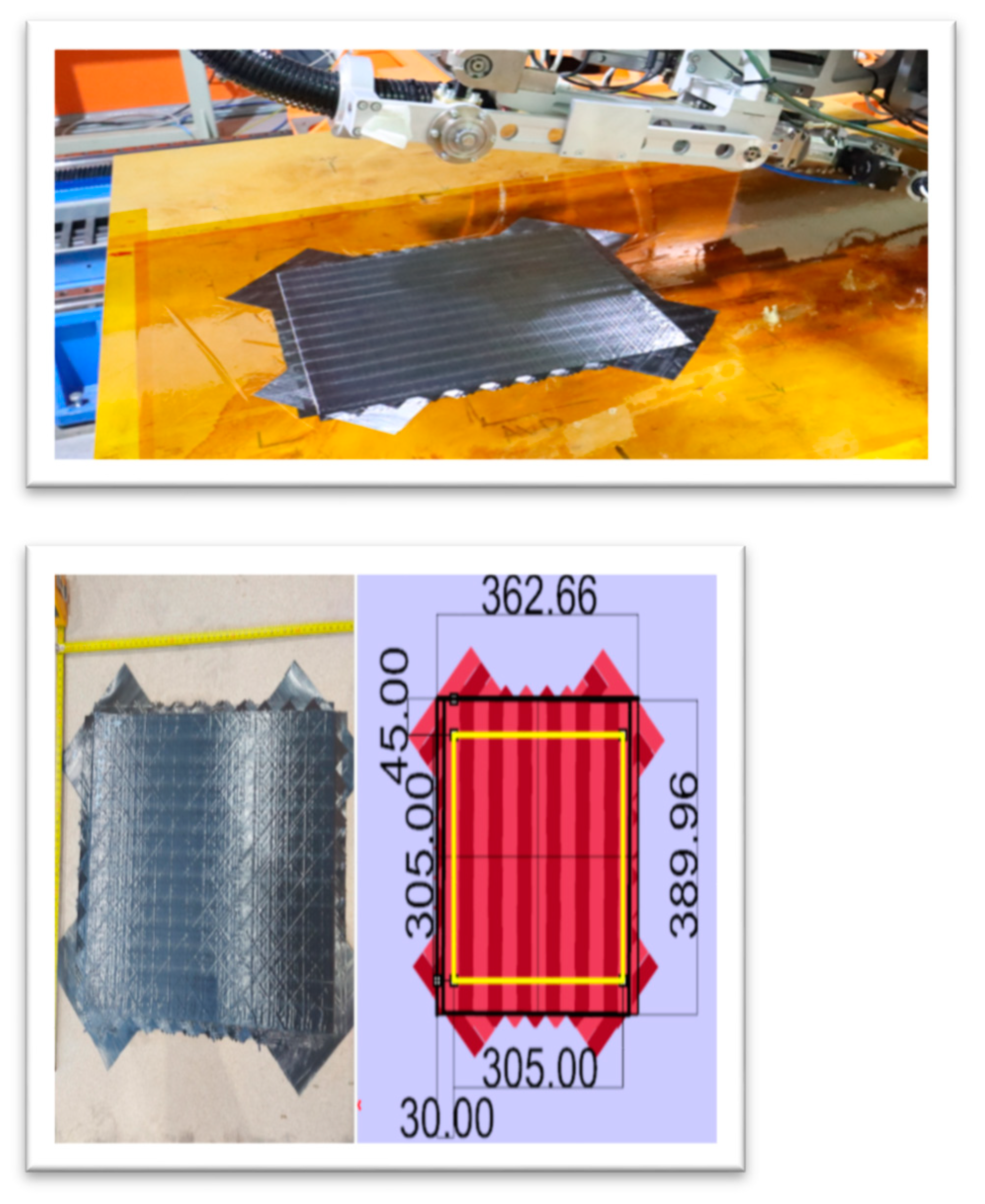
2.2. LATP Process (Laser-Assisted ATP Manufacturing)
- Consolidation roller with outer diameter of 60 mm
- Spool for UD tape
- Laser Heat source 3 kW Laser line LDF series diode laser system (optic lens 33 × 43 mm and focal distance 200 mm).
- Mandrel/Tool
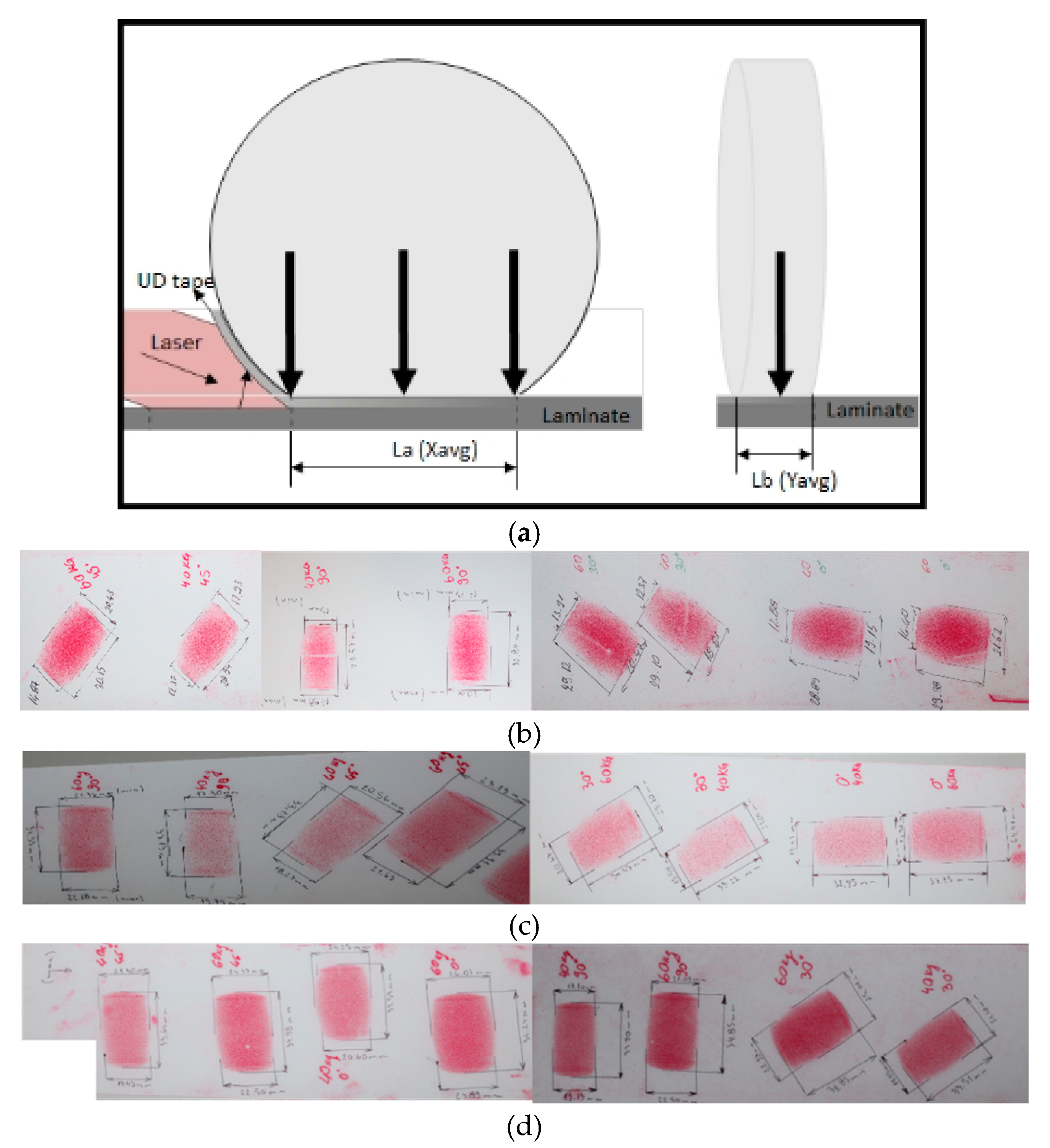
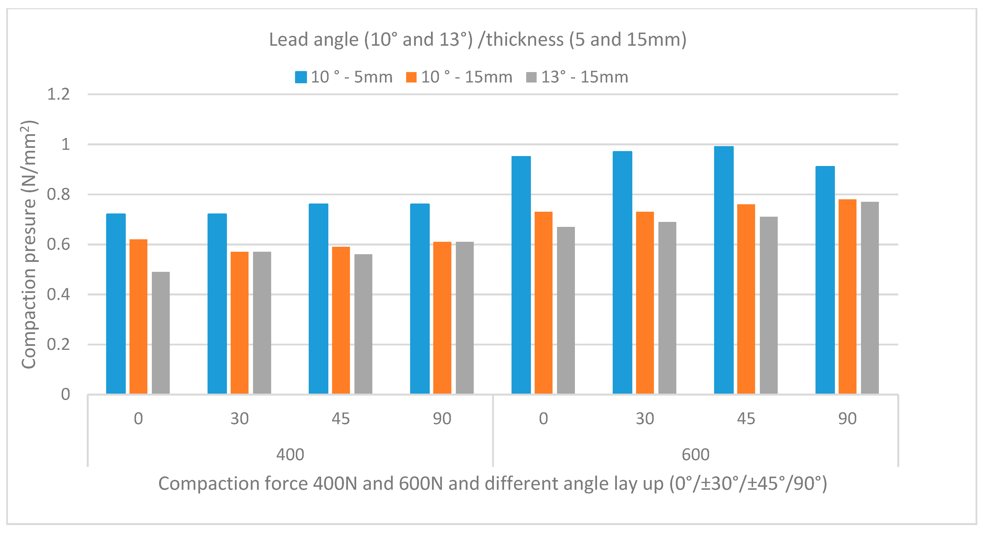
2.3. Pressure Measurement
- -
- Compact force (400–600 N)
- -
- Thickness of the siliconized layer of the roller (P1 thickness of silicon 5 mm and P2 thickness of silicon 15 mm)
- -
- Tilt angle of the head (10–13 deg)
- -
- Angle of lay up (0, 45, −45, 90 deg)
2.4. ILSS and Void
3. Results and Discussion
3.1. The Factors Affect the Expansion of the Tape
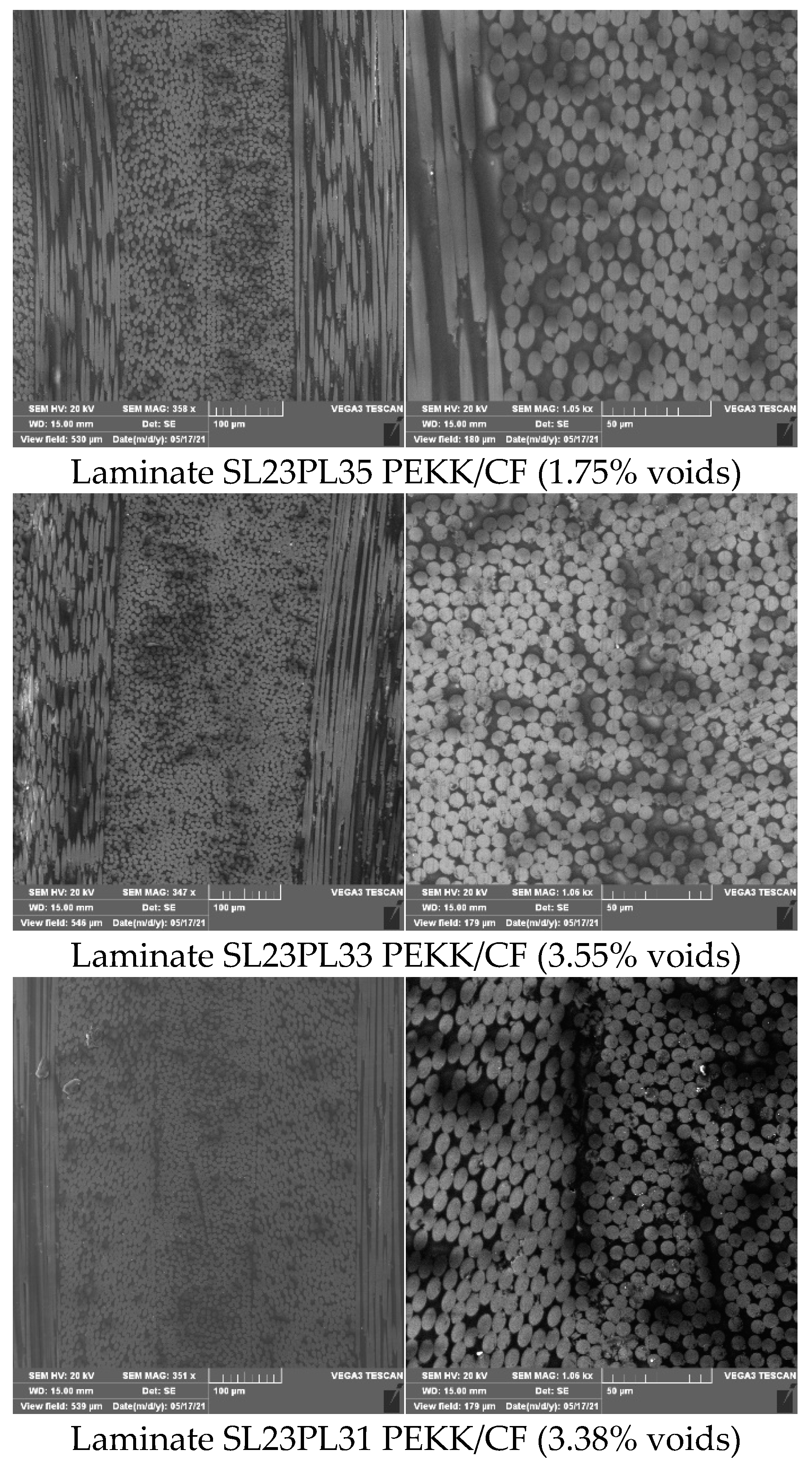
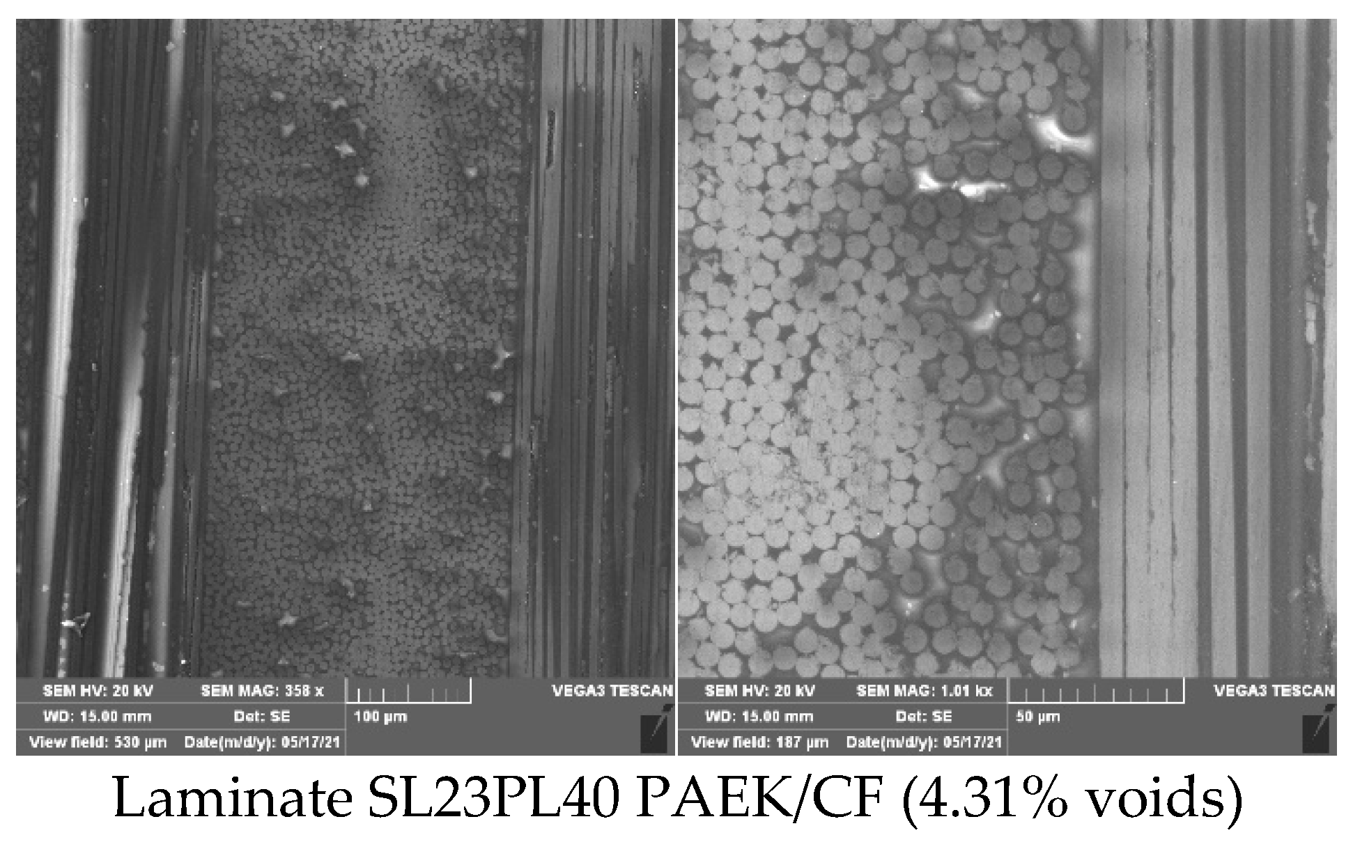
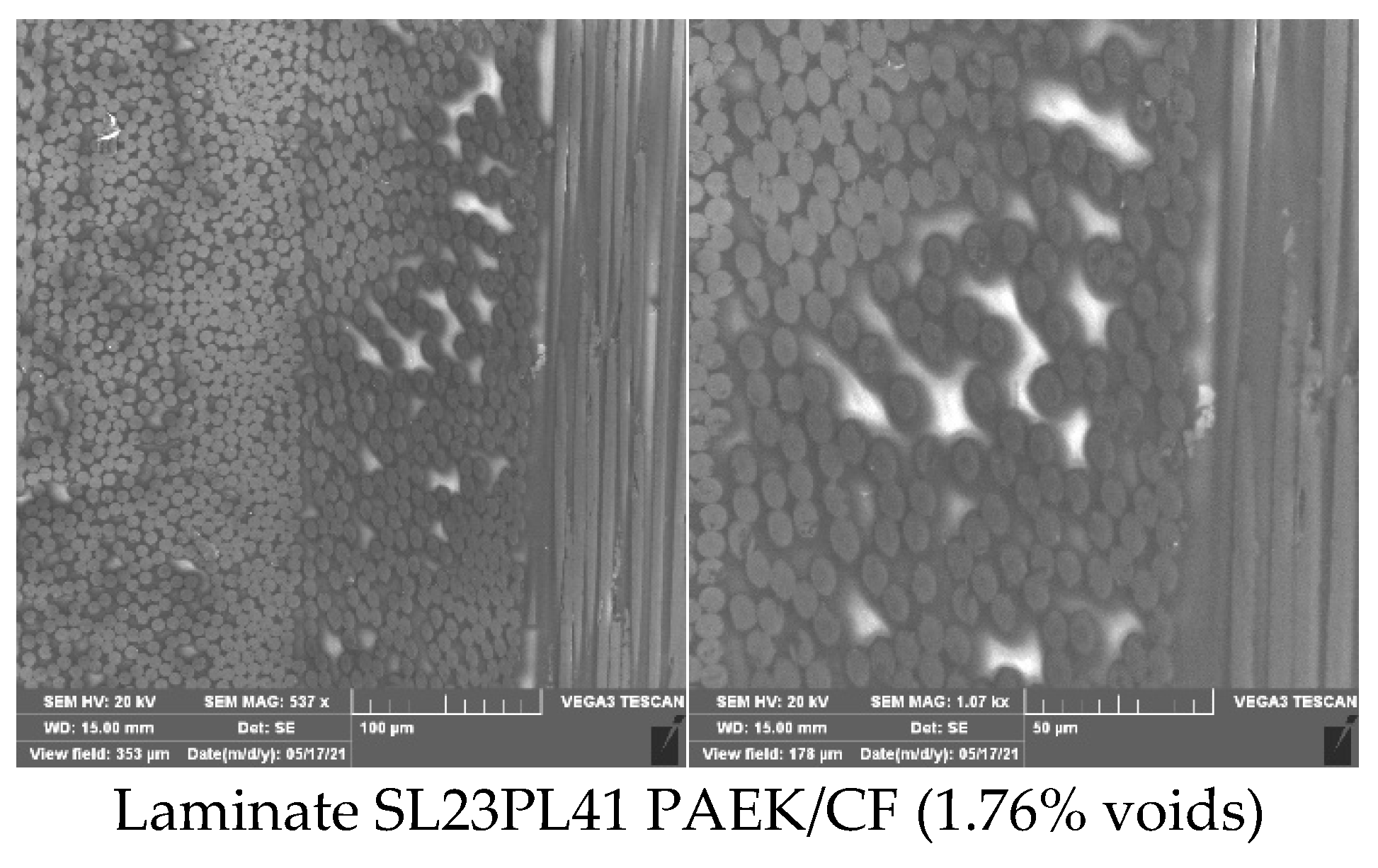
3.2. ILSS and Void
4. Conclusions
- The results confirmed that each laying angle of the laminate gives a different contact surface.
- From all four types of angles in this paper, the angle of laying in the direction of the fibers (0) gave the largest surface; thus, giving good intimate contact for good consolidation and adhesion on the stencil, and thus gluing layer by layer.
- For QI laminate with other angles (±45; ±30; 90), we need to increase or decrease the compaction force (according to Figure 6 and Figure 7) to have a similar compact line (surface), as well as for the laying of the fibers in the direction (0) in order to have an even bonding of the layers without gap and overlap.
- The minimum lay-up speed and the maximum compact force for both materials have the best results (low porosity less than 2%).
- The selected parameters for the samples with PEEK resin have better mechanical characteristics than the PAEK samples. The reason for that may be the greater flow of the PAEK resin, which can be seen from the SEM images.
Author Contributions
Funding
Institutional Review Board Statement
Informed Consent Statement
Data Availability Statement
Acknowledgments
Conflicts of Interest
References
- Lee, W.I.; Springer, G.S. A model of the manufacturing process of thermoplastic matrix composites. J. Compos. Mater. 1987, 21, 1017–1055. [Google Scholar] [CrossRef]
- Yang, F.; Pitchumani, R. A fractal Cantor set based description of interlaminar contact evolution during thermoplastic composites processing. J. Mater. Sci 2001, 36, 4661–4671. [Google Scholar] [CrossRef]
- Schaefer, P.M.; Guglhoer, T.; Sause, M.G.; Drechsler, K. Development of intimate contact during processing of carbon fiber reinforced Polyamide-6 tapes. J. Reinf. Plast. Compos. 2017, 36, 593–607. [Google Scholar] [CrossRef]
- Mantell, S.C.; Springer, G.S. Manufacturing process models for thermoplastic composites. J. Compos. Mater. 1992, 26, 2348–2377. [Google Scholar] [CrossRef]
- Khan, M.A.; Mitschang, P.; Schledjewski, R. Parametric study on processing parameters and resulting part quality through thermoplastic tape placement process. J. Compos. Mater. 2013, 47, 485–499. [Google Scholar] [CrossRef]
- Stokes-Griffin, C.M.; Compston, P. Investigation of sub-melt temperature bonding of carbon-fibre /PEEK in an automated laser tape placement process. Compos. Part A Appl. Sci. Manuf. 2016, 84, 17–25. [Google Scholar] [CrossRef]
- Jiang, J.; He, Y.; Ke, Y. Pressure distribution for automated fiber placement and design optimization of compaction rollers. J. Reinf. Plast. Compos. 2019, 38, 860–870. [Google Scholar] [CrossRef]
- Stokes-Griffin, C.M.; Compston, P. A combined optical-thermal model for near-in-frared laser heating of thermoplastic composites in an automated tape placement process. Compos. Part A Appl. Sci. Manuf. 2015, 75, 104–115. [Google Scholar] [CrossRef]
- Grouve, W.J.B.; Warnet, L.L.; Rietman, B.; Visser, H.A.; Akkerman, R. Optimization of the tape placement process parameters for carbon-PPS composites. Compos. Part A Appl. Sci. Manuf. 2013, 50, 44–53. [Google Scholar] [CrossRef]
- Leon, A.; Argerich, C.; Barasinski, A.; Soccard, E.; Chinesta, F. Effects of material and process parameters on in-situ consolidation. Int. J. Mater. Form. 2019, 12, 491–503. [Google Scholar] [CrossRef]
- Coulson, M.; Dantras, E.; Olivier, P.; Gleizes, N.; Lacabanne, C. Thermal conductivity and diffusivity of carbon-reinforced polyetherketoneketone composites. J. Appl. Polym. Sci. 2019, 136, 47975. [Google Scholar] [CrossRef] [Green Version]
- Grouve, W.J.B.; Warnet, L.L.; Rietman, B.; Akkerman, R. On the weld strength of in situ tape placed reinforcements on weave reinforced structures. Compos. Part A Appl. Sci. Manuf. 2012, 43, 1530–1536. [Google Scholar] [CrossRef]
- Barasinski, A.; Leygue, A.; Soccard, E.; Poitou, A. Identification of non uniform thermal contact resistance in automated tape placement process. Int. J. Mater. Form. 2014, 7, 479–486. [Google Scholar] [CrossRef] [Green Version]
- Simacek, P.; Advani, S.G.; Gruber, M.B.; Jensen, B. A non-local void filling model to describe its dynamics during processing thermoplastic composites. Compos. Part. A Appl. Sci. Manuf. 2013, 46, 154–165. [Google Scholar] [CrossRef]
- Mehdikhani, M.; Gorbatikh, L.; Verpoest, I.; Lomov, S.V. Voids in fiber-reinforced polymer composites: A review on their formation, characteristics, and effects on mechanical performance. J. Compos. Mater. 2019, 53, 1579–1669. [Google Scholar] [CrossRef]
- Stokes-Griffin, C.M.; Compston, P. The effect of processing temperature and placement rate on the short beam strength of carbon fibre-PEEK manufactured using a laser tape placement process. Compos. Part A Appl. Sci. Manuf. 2015, 78, 274–283. [Google Scholar] [CrossRef]
- Weiler, T.; Emonts, M.; Wollenburg, L.; Janssen, H. Transient thermal analysis of laser-assisted thermoplastic tape placement at high process speeds by use of analytical solutions. J. Thermoplast. Compos. Mater. 2018, 31, 311–338. [Google Scholar] [CrossRef]
- Butler, C.A.; McCullough, R.L. An analysis of mechanisms governing fusion bonding of thermoplastic composites. J. Thermoplast. Compos. Mater. 1998, 11, 339–363. [Google Scholar] [CrossRef]
- Levy, A.; Heider, D.; Tierney, J.; Gillespie, J.W. Inter-layer thermal contact resistance evolution with the degree of intimate contact in the processing of thermoplastic composite laminates. J. Compos. Mater. 2014, 48, 491–503. [Google Scholar] [CrossRef]
- Tierney, J.; Gillespie, J.W. Modeling of in situ strength development for the thermoplastic composite tow placement process. J. Compos. Mater. 2006, 40, 1487–1506. [Google Scholar] [CrossRef]
- Zarandi, M.A.F.; Arroyo, S.; Pillai, K.M. Longitudinal and transverse flows in fiber tows: Evaluation of theoretical permeability models through numerical predictions and experimental measurements. Compos. Part A Appl. Sci. Manuf. 2019, 119, 73–87. [Google Scholar] [CrossRef]
- Kok, T. On the Consolidation Quality in Laser Assisted Fiber Placement: The Role of the Heating Phase. Ph.D. Thesis, University of Twente, Enschede, The Netherlands, 2018. [Google Scholar] [CrossRef] [Green Version]
- Comer, A.J.; Ray, D.; Obande, W.O.; Jones, D.; Lyons, J.; Rosca, I.; Higgins, R.M.O.; McCarthy, M.A. Mechanical characterisation of carbon fibre-PEEK manufactured by laser-assisted automated-tape- placement and autoclave. Compos. Part A Appl. Sci. Manuf. 2015, 69, 10–20. [Google Scholar] [CrossRef]
- Lichtinger, R.; Lacalle, J.; Hinterh€olzl, R.; Beier, U.; Drechsler, K. Simulation and experimental validation of gaps and bridging in the automated fiber placement process. Sci. Eng. Compos. Mater. 2015, 22, 131–148. [Google Scholar] [CrossRef]
- Lukaszewicz, D.-J.; Potter, K. Through-thickness compression response of uncured prepreg during manufacture by automated layup. Proc. Inst. Mech. Eng. Part B J. Eng. Manuf. 2012, 226, 193–202. [Google Scholar] [CrossRef]
- Cheng, J.; Zhao, D.; Liu, K.; Wang, Y.; Chen, H. Modeling and impact analysis on contact characteristic of the compaction roller for composite automated placement. J. Reinf. Plast. Compos. 2018, 37, 1418–1432. [Google Scholar] [CrossRef]
- Samak, S.; Risteska, S.; Dukovski, V.; Trajkoski, S. Some experimental investigation of products from thermoplastic composite materials manufactured with robot and LAFP. Int. J. Eng. Res. Technol. 2020, 9, 9. Available online: https://www.ijert.org/some-experimental-investigation-of-products-from-thermoplastic-composite-materials-manufactured-with-robot-and-lafp (accessed on 15 September 2021).
- Saffar, F.; Sonnenfeld, C.; Beauchêne1, P.; Park, C.H. In-situ Monitoring of the Out-Of-Autoclave Consolidation of Carbon/Poly-Ether-Ketone-Ketone Prepreg Laminate. Front. Mater. 2020, 7, 195. [Google Scholar] [CrossRef]
- Thor, M.; Sause, M.G.R.; Hinterhölzl, R.M. Mechanisms of Origin and Classification of Out-of-Plane Fiber Waviness in Composite Materials—A Review. J. Compos. Sci. 2020, 4, 130. [Google Scholar] [CrossRef]
- Celik, O.; Peeters, D.; Dransfeld, C.; Teuwen, J. Intimate contact development during laser assisted fiber placement: Microstructure and effect of process parameters. Compos. Part A: Appl. Sci. Manuf. 2020, 134, 105888. [Google Scholar] [CrossRef]
- Baho, O.; Ausias, G.; Grohens, Y.; Férec, J. Simulation of laser heating distribution for a thermoplastic composite: Effects of AFP head parameters. Int. J. Adv. Manuf. Technol. 2020, 110, 2105–2117. [Google Scholar] [CrossRef]
- Srebrenkoska, S.; Dukovski, V.; Risteska, S. Influence of the process parameters on laser—Assisted automated tape placement process. Int. J. Eng. Res. Technol. 2020, 9, 11. Available online: https://www.ijert.org/influence-of-the-process-parameters-on-laser-assisted-automated-tape-placement-process (accessed on 15 September 2021).
- Stokes-Griffin, C.M.; Compston, P. An inverse model for optimisation of laser heat flux distributions in an automated laser tape placement process for carbon-fibre/PEEK. Compos. Part. A Appl. Sci. Manuf. 2016, 88, 190–197. [Google Scholar] [CrossRef] [Green Version]
- Kim, Y.H.; Wool, R.P. A theory of healing at a polymer-polymer interface. Macromolecules 1983, 16, 1115–1120. [Google Scholar] [CrossRef]


| Materials | LM-PAEK Toray TC1225 Cetex®/T700 | PEKK/CF Ten Cate TC1320/AS4 |
|---|---|---|
| Prepreg areal weight | 220 g/m² | 220 g/m² |
| Fiber areal weight | 145 g/m² | 145 g/m² |
| Matrix content | 34 wt.% | 34 wt.% |
| Nominal thickness | 0.14 mm | 0.14 mm |
| Matrix glass transition temperature (Tg) | 147 °C | 160 °C |
| Matrix melting temperature (Tm) | 305 °C | 337 °C |
| Roller 1(P1) | Roller 2(P2) | Roller 2(P2) | |||||||||
|---|---|---|---|---|---|---|---|---|---|---|---|
| Diameter ø60, Wide 35 mm, Thickness of Silicon 5 mm | Diameter ø60, Wide 35 mm, Thickness of Silicon 15 mm | Diameter ø60, Wide 35 mm, Thickness of Silicon 15 mm | |||||||||
| Angle of lay up | Compaction force | Contact line La (mm) | Pressure | Contact line La (mm) | Pressure | Contact line La (mm) | Pressure | ||||
| (N) | (Lead angle 10°) | N/mm2 | (Lead angle 10°) | N/mm2 | (Lead angle 13°) | N/mm2 | |||||
| 1 | 0 | 400 | 19.15 | 553 | 0.72 | 19.987 | 641.54 | 0.62 | 22.425 | 813.1 | 0.49 |
| 3 | ±30 | 400 | 19.06 | 554.97 | 0.72 | 19.81 | 698.95 | 0.57 | 20.445 | 707.06 | 0.57 |
| 5 | ±45 | 400 | 18.34 | 529.565 | 0.76 | 18.62 | 682.18 | 0.59 | 20.375 | 716.53 | 0.56 |
| 7 | 90 | 400 | 17.89 | 528.71 | 0.76 | 19.415 | 653.99 | 0.61 | 18.615 | 652.34 | 0.61 |
| 2 | 0 | 600 | 21.52 | 632 | 0.95 | 22.996 | 823.84 | 0.73 | 24.98 | 892.64 | 0.67 |
| 4 | ±30 | 600 | 20.85 | 619 | 0.97 | 22.185 | 818.36 | 0.73 | 23.995 | 871.6 | 0.69 |
| 6 | ±45 | 600 | 20.33 | 609 | 0.99 | 22.38 | 784.34 | 0.76 | 23.615 | 851.06 | 0.71 |
| 8 | 90 | 600 | 20.01 | 657 | 0.91 | 21.77 | 765.87 | 0.78 | 21.795 | 784.12 | 0.77 |
| Parameters | Void Calculations via Theoretical Density | |||||||||
| Code | N | (m/min) | No. | (g/cm3) | (g/cm3) | (%) | Voids Average (%) | |||
| Compaction Force | Lay up Speed | Samp. | Md | Td Averge | Voids | Vav (%) | Sn-1 | CV | ||
| S23PL33 | 200 | 3 | 1 | 1.542 | 1.59 | 3.019 | 3.55 | 0.39 | 10.97 | |
| 200 | 3 | 2 | 1.525 | 1.59 | 4.088 | |||||
| 200 | 3 | 3 | 1.533 | 1.59 | 3.585 | |||||
| 200 | 3 | 4 | 1.532 | 1.59 | 3.648 | |||||
| 200 | 3 | 5 | 1.536 | 1.59 | 3.396 | |||||
| S23PL35 | 1000 | 3 | 1 | 1.56 | 1.59 | 1.887 | 1.75 | 0.14 | 8.18 | |
| 1000 | 3 | 2 | 1.616 | 1.59 | 1.900 | |||||
| 1000 | 3 | 3 | 1.569 | 1.59 | 1.671 | |||||
| 1000 | 3 | 4 | 1.563 | 1.59 | 1.698 | |||||
| 1000 | 3 | 5 | 1.565 | 1.59 | 1.572 | |||||
| S23PL31 | 200 | 6 | 1 | 1.537 | 1.59 | 3.333 | 3.38 | 0.20 | 5.94 | |
| 200 | 6 | 2 | 1.532 | 1.59 | 3.648 | |||||
| 200 | 6 | 3 | 1.538 | 1.59 | 3.270 | |||||
| 200 | 6 | 4 | 1.54 | 1.59 | 3.145 | |||||
| 200 | 6 | 5 | 1.534 | 1.59 | 3.522 | |||||
| S23PL32 | 1000 | 6 | 1 | 1.55 | 1.59 | 2.216 | 2.28 | 0.10 | 4.38 | |
| 1000 | 6 | 2 | 1.532 | 1.59 | 2.248 | |||||
| 1000 | 6 | 3 | 1.551 | 1.59 | 2.208 | |||||
| 1000 | 6 | 4 | 1.508 | 1.59 | 2.452 | |||||
| 1000 | 6 | 5 | 1.54 | 1.59 | 2.285 | |||||
| S23PL40 | 200 | 3 | 1 | 1.512 | 1.59 | 4.906 | 4.31 | 0.40 | 9.16 | |
| 200 | 3 | 2 | 1.508 | 1.59 | 4.507 | |||||
| 200 | 3 | 3 | 1.53 | 1.59 | 3.974 | |||||
| 200 | 3 | 4 | 1.537 | 1.59 | 3.983 | |||||
| 200 | 3 | 5 | 1.52 | 1.59 | 4.203 | |||||
| S23PL41 | 1000 | 3 | 1 | 1.572 | 1.59 | 1.532 | 1.76 | 0.20 | 11.45 | |
| 1000 | 3 | 2 | 1.532 | 1.59 | 1.780 | |||||
| 1000 | 3 | 3 | 1.579 | 1.59 | 1.692 | |||||
| 1000 | 3 | 4 | 1.541 | 1.59 | 2.082 | |||||
| 1000 | 3 | 5 | 1.586 | 1.59 | 1.716 | |||||
| S23PL38 | 200 | 6 | 1 | 1.523 | 1.59 | 4.214 | 4.86 | 0.47 | 9.57 | |
| 200 | 6 | 2 | 1.503 | 1.59 | 5.472 | |||||
| 200 | 6 | 3 | 1.503 | 1.59 | 4.707 | |||||
| 200 | 6 | 4 | 1.506 | 1.59 | 5.083 | |||||
| 200 | 6 | 5 | 1.529 | 1.59 | 4.836 | |||||
| S23PL39 | 1000 | 6 | 1 | 1.502 | 1.59 | 3.535 | 3.75 | 0.35 | 9.28 | |
| 1000 | 6 | 2 | 1.521 | 1.59 | 4.340 | |||||
| 1000 | 6 | 3 | 1.534 | 1.59 | 3.722 | |||||
| 1000 | 6 | 4 | 1.546 | 1.59 | 3.707 | |||||
| 1000 | 6 | 5 | 1.551 | 1.59 | 3.453 | |||||
| Parameters | Mechanical Properties—ILSS | |||||||||
| Code | Compaction Force | Lay up Speed | Sam. | Width | Thickness | Loading Force | τ | τ av | Sn-1 | CV |
| N | (m/min) | No. | (mm) | (mm) | (N) | (MPa) | (MPa) | |||
| S23PL33 | 200 | 3 | 1 | 13.38 | 2.17 | 2377 | 61.40 | 61.42 | 5.71 | 9.30 |
| 200 | 3 | 2 | 13.42 | 2.26 | 2505 | 61.95 | ||||
| 200 | 3 | 3 | 13.26 | 2.30 | 2160 | 53.12 | ||||
| 200 | 3 | 4 | 13.27 | 2.13 | 2314 | 61.40 | ||||
| 200 | 3 | 5 | 13.13 | 2.13 | 2582 | 69.24 | ||||
| S23PL35 | 1000 | 3 | 1 | 13.44 | 2.00 | 2338 | 65.23 | 64.47 | 5.48 | 8.50 |
| 1000 | 3 | 2 | 13.03 | 1.87 | 2360 | 72.64 | ||||
| 1000 | 3 | 3 | 12.98 | 1.99 | 2006 | 58.25 | ||||
| 1000 | 3 | 4 | 13.03 | 2.01 | 2125 | 60.85 | ||||
| 1000 | 3 | 5 | 12.95 | 2.06 | 2325 | 65.37 | ||||
| S23PL31 | 200 | 6 | 1 | 13.14 | 2.31 | 2214 | 54.71 | 55.42 | 5.36 | 9.67 |
| 200 | 6 | 2 | 13.40 | 2.25 | 2302 | 57.26 | ||||
| 200 | 6 | 3 | 13.23 | 2.13 | 1836 | 48.86 | ||||
| 200 | 6 | 4 | 13.01 | 2.26 | 2076 | 52.95 | ||||
| 200 | 6 | 5 | 13.40 | 2.17 | 2454 | 63.30 | ||||
| S23PL32 | 1000 | 6 | 1 | 13.16 | 2.08 | 2028 | 55.57 | 56.81 | 5.25 | 9.24 |
| 1000 | 6 | 2 | 12.83 | 2.11 | 2150 | 59.56 | ||||
| 1000 | 6 | 3 | 12.54 | 2.12 | 1850 | 52.19 | ||||
| 1000 | 6 | 4 | 13.22 | 2.10 | 2387 | 64.49 | ||||
| 1000 | 6 | 5 | 12.58 | 2.23 | 1954 | 52.24 | ||||
| S23PL40 | 200 | 3 | 1 | 12.96 | 2.24 | 1988 | 51.36 | 49.22 | 1.76 | 3.58 |
| 200 | 3 | 2 | 12.28 | 2.19 | 1823 | 50.84 | ||||
| 200 | 3 | 3 | 13.20 | 2.24 | 1909 | 48.42 | ||||
| 200 | 3 | 4 | 13.51 | 2.21 | 1887 | 47.4 | ||||
| 200 | 3 | 5 | 13.3 | 2.23 | 1902 | 48.1 | ||||
| S23PL41 | 1000 | 3 | 1 | 13.32 | 2.34 | 2077 | 49.98 | 51.31 | 1.62 | 3.16 |
| 1000 | 3 | 2 | 12.83 | 2.31 | 2063 | 52.21 | ||||
| 1000 | 3 | 3 | 13.17 | 2.23 | 2091 | 53.40 | ||||
| 1000 | 3 | 4 | 13.13 | 2.22 | 2003 | 51.54 | ||||
| 1000 | 3 | 5 | 13.31 | 2.20 | 1930 | 49.43 | ||||
| S23PL38 | 200 | 6 | 1 | 13.21 | 2.20 | 1765 | 45.55 | 44.52 | 3.19 | 7.16 |
| 200 | 6 | 2 | 13.27 | 2.15 | 1813 | 47.66 | ||||
| 200 | 6 | 3 | 13.31 | 2.19 | 1760 | 45.28 | ||||
| 200 | 6 | 4 | 13.36 | 2.08 | 1666 | 44.96 | ||||
| 200 | 6 | 5 | 13.25 | 2.01 | 1390 | 39.14 | ||||
| S23PL39 | 1000 | 6 | 1 | 12.37 | 2.04 | 1859 | 55.25 | 54.75 | 4.85 | 8.85 |
| 1000 | 6 | 2 | 12.92 | 2.10 | 1689 | 46.69 | ||||
| 1000 | 6 | 3 | 12.25 | 2.08 | 1946 | 57.28 | ||||
| 1000 | 6 | 4 | 12.85 | 2.16 | 2038 | 55.07 | ||||
| 1000 | 6 | 5 | 12.81 | 2.10 | 2133 | 59.47 | ||||
Publisher’s Note: MDPI stays neutral with regard to jurisdictional claims in published maps and institutional affiliations. |
© 2021 by the authors. Licensee MDPI, Basel, Switzerland. This article is an open access article distributed under the terms and conditions of the Creative Commons Attribution (CC BY) license (https://creativecommons.org/licenses/by/4.0/).
Share and Cite
Risteska, S.; Samak, S.; Samak, V. The Factors That Affect the Expansion of the Tape for It to Avoid Side Effects in the Production of Composites in Online LATP Technology. J. Compos. Sci. 2021, 5, 284. https://doi.org/10.3390/jcs5100284
Risteska S, Samak S, Samak V. The Factors That Affect the Expansion of the Tape for It to Avoid Side Effects in the Production of Composites in Online LATP Technology. Journal of Composites Science. 2021; 5(10):284. https://doi.org/10.3390/jcs5100284
Chicago/Turabian StyleRisteska, Svetlana, Samoil Samak, and Vele Samak. 2021. "The Factors That Affect the Expansion of the Tape for It to Avoid Side Effects in the Production of Composites in Online LATP Technology" Journal of Composites Science 5, no. 10: 284. https://doi.org/10.3390/jcs5100284
APA StyleRisteska, S., Samak, S., & Samak, V. (2021). The Factors That Affect the Expansion of the Tape for It to Avoid Side Effects in the Production of Composites in Online LATP Technology. Journal of Composites Science, 5(10), 284. https://doi.org/10.3390/jcs5100284