Article

Mechanical and Microstructural Assessment of Inhomogeneities in Oxide Ceramic Matrix Composites Detected by Air-Coupled Ultrasound Inspection

1
Institute of Materials Research, German Aerospace Center (DLR), 51147 Cologne, Germany
2
Institute of Structures and Design, German Aerospace Center (DLR), 70569 Stuttgart, Germany
*
Author to whom correspondence should be addressed.
J. Compos. Sci. 2021, 5(11), 286; https://doi.org/10.3390/jcs5110286
Submission received: 30 July 2021 / Revised: 1 October 2021 / Accepted: 18 October 2021 / Published: 23 October 2021
(This article belongs to the Special Issue Ceramic-Matrix Composites)

Abstract

:
Ceramic Matrix Composites (CMC) are promising materials for high-temperature applications where damage tolerant failure behavior is required. Non-destructive testing is essential for process development, monitoring, and quality assessment of CMC parts. Air-coupled ultrasound (ACU) is a fast and cost-efficient tool for non-destructive inspections of large components with respect to the detection of material inhomogeneities. Even though ACU inspection is usually used for visual inspection, the interpretation of C-scan images is often ambiguous with regard to critical defects and their impact on local material properties. This paper reports on a new approach to link the local acoustic damping of an oxide CMC plate obtained from ACU analysis with subsequent destructive mechanical testing and microstructural analyses. Local damping values of bending bars are extracted from ACU maps and compared with the results of subsequent resonant frequency damping analysis and 3-point bending tests. To support data interpretation, the homogeneous and inhomogeneous CMC areas detected in the ACU map are further analyzed by X-ray computed tomography and scanning electron microscopy. The results provide strong evidence that specific material properties such as Young’s modulus are not predictable from ACU damping maps. However, ACU shows a high, beneficial sensitivity for narrow but large area matrix cracks or delaminations, i.e., local damping is significantly correlated with specific properties such as shear moduli and bending strengths.

1. Introduction

Oxide Ceramic Matrix Composites (Ox-CMC) with porous matrices have been developed since the mid-1990s and have been commercially available since the early 2000s. Porous Ox-CMC provide a unique combination of properties, e.g., high thermal resistance, damage tolerant failure behavior, and good corrosion resistance, which makes them promising materials for light weight, high-temperature structural applications for aerospace such as ducts, nozzles, or mixers for exhaust gases of turbine engines [1,2]. State-of-the-art Ox-CMC typically consist of continuous alumina (α-Al2O3, corundum) or aluminosilicate (Al6Si2O13, mullite) fibers and porous matrices of micro- to nanoscaled α-Al2O3, Al6Si2O13, and mixtures thereof. Some Ox-CMC also include additional zirconia (ZrO2) to prevent excessive grain growth and densification of the porous matrices. Typical matrix porosities are in the range of 30 to 50 vol%. With typical fiber volume contents between 30 and 50 vol%, total porosities of Ox-CMC range between 15 to 35 vol%. A high matrix porosity inevitably results in relative low strength and toughness. Consequently, this class of materials is commonly referred to as “Weak Matrix Composites”. Fracture is substantially governed by microcracking and disintegration of the porous, low toughness ceramic matrix prior to fiber rupture. This results in the typical ‘failure-tolerant’ behavior of porous Ox-CMC.
Ox-CMC are manufactured, similar to other fiber reinforced materials, by lamination of woven fabrics or filament winding, frequently supported by vacuum assisted infiltration or consolidation in vacuum bags or autoclaves [3,4]. A distinct feature of most Ox-CMC is the use of particulate matrix precursors, i.e., fine ceramic particles dispersed in a liquid with a high solid content (‘slurries’). Most of the routes reported in the literature rely on water-based slurries [5]. Unlike polymers, consolidation of these matrix precursors requires the removal of the liquid by evaporation. The associated volume loss can cause excessive shrinkage and trigger the formation of matrix cracks (‘mud cracks’), particularly in areas where only a few fibers are able to bridge such cracks. Subsequent consolidation of the CMC by sintering at temperatures up to 1300 °C can cause additional matrix shrinkage, i.e., existing drying cracks can expand and additional sintering-induced cracks are generated. The fact that most porous Ox-CMC exhibit a laminar fiber architecture implies that matrix-dominated interlaminar areas are predominantly prone to shrinkage-related cracking, i.e., the already low interlaminar (matrix) strength may be further reduced, thereby increasing the risk of shear failure. Comprehensive review articles on manufacturing, properties, and application of Ox-CMC can be found, e.g., in references [6,7,8].
Detection and interpretation of these kinds of manufacturing-related flaws are essential for quality assurance of porous Ox-CMC. As the location and size of these critical flaws are considered to be distributed randomly, large area inspection of CMC parts is mandatory [9]. A common non-destructive method is X-ray computed tomography (XCT). XCT is the method of choice if detailed information of the composite mesostructure, e.g., position and orientation of large voids, matrix enrichments, etc. is required. However, as the voxel resolution of XCT is inversely proportional to the sample volume high fidelity imaging of microsized features is mostly limited to small sample volumes. On the other hand, optically excited lock-in thermography, 3D terahertz inspection, or air-coupled ultrasound (ACU) inspection provide less resolution compared to XCT, but allow a much faster and relatively straightforward measurement and analysis of large CMC components [10,11,12]. In particular, the method of air-coupled ultrasonic testing shows great potential in the investigation of composites and has been the subject of many publications in recent years, e.g., in the automated testing of large components [13], the use of Lamb waves [14], assessment of impact damage [15,16], detection of internal flaws or delamination [17,18,19,20,21] and bonding quality evaluation [22].
The scope of this work was to find and quantify possible correlation between features detected by ACU mapping and local material properties of an Ox-CMC plate. For this purpose, acoustic damping data of individual bending bars was collected and quantified from ACU maps. The data from homogeneous and inhomogeneous sample areas were compared and correlated with results from resonant frequency damping analysis (frequently referred to as ‘impulse excitation technique’) and destructive bending tests.

2. Methodology

2.1. Material

An Ox-CMC plate with a size of 480 × 305 × 3 mm3 manufactured by Schunk Kohlenstofftechnik GmbH (Heuchelheim, Germany) was used for the purpose of this investigation. The plate was made of 8 layers of NextelTM 610 3000 den satin fabric (8HSS) with a fiber orientation of 0/90° and a porous Al2O3 and ZrO2 matrix. The CMC was manufactured by a prepreg layup with subsequent autoclave process and sintering. The as received CMC panel had a density of 3.0 g/cm3, a porosity of 26.2%, and a fiber volume fraction of 44.6%. The Ox-CMC plate was tested in the as sintered state, i.e., without machined surfaces.

2.2. Air-Coupled Ultrasound Inspection (ACU)

Non-destructive mapping of the CMC plate was performed by air-coupled ultrasound inspection (FlatScan 1000 AirTech with USPC 4000 AirTech module, Hillger-NDT, Braunschweig, Germany) with AirTech 200 transducers in transmission mode. The testing frequency was 200 kHz and horizontal and vertical step size during measurement was 0.6 mm, respectively. From selected CMC areas appearing ‘homogeneous’ and ‘inhomogeneous’ in the amplitude-based C-scan image, 90 × 10 mm2 bending bars were cut by a diamond saw. Two principal cutting directions were defined in order to obtain samples with ±45° and 0/90° fiber orientation. Quantitative damping values for each bending bar were extracted from the ACU raw data by a self-developed Python-based script.

2.3. Resonant Frequency Damping Analysis (RFDA)

Elastic properties of bending bars were measured by resonant frequency and damping analysis (RFDA Professional, IMCE NV, Genk, Belgium) using a 3 mm metal projectile, a node-distance of 49.9 mm, and an impulse power of 52%. The automatic excitation unit and the microphone were positioned at diagonally opposite corners to test the sample simultaneously in torsional and flexural vibration mode. The measured frequencies were in the range of F(flexural) 1976–2049 Hz and F(torsional) 7513–7883 Hz for the 0/90° fiber orientation and F(flexural) 1657–1727 Hz and F(torsional) 9183–10,055 Hz for the ±45° fiber orientation.

2.4. X-ray Computed Tomography

Non-destructive analyses of selected bending bars were performed by micro-focus computed tomography (µCT, v|tome|x L, GE Sensing & Inspection Technologies GmbH, Wunstorf, Germany). A small volume of 20 × 10 × 3 mm3 from the specimen’s central part (i.e., estimated loading/failure zone during bending test) was scanned. The minimum voxel size of CT-scans was 12 μm3.

2.5. Mechanical and Microstructural Analysis

Three-point bending tests were performed in a universal testing system (UTS 10, Zwick-Roell, Ulm, Germany) at a support span of 80 mm and a cross head speed of 2 mm/min. Force was measured with a 2.5 kN load cell A.S.T. KAF-TC. Displacement of the specimen was measured inductively with a Millitron 1310 system in the center of the bending specimen, and additionally at −15 mm and +15 mm from the center to determine only the specimen deformation without any deformation of the fixtures or loading system. The bending modulus was determined using a linear fit for a defined stress interval (±45°: 15–35 MPa and 0/90°: 20–50 MPa) in the linear elastic region of the stress–strain curve. Microstructural analyses were performed by scanning electron microscopy (Ultra 55, Carl Zeiss Microscopy, Oberkochen, Germany).
A schematic overview of sample selection and experimental methodology is presented in Figure 1.

3. Results and Discussion

3.1. Air-Coupled Ultrasound Inspection of the Ox-CMC Plate

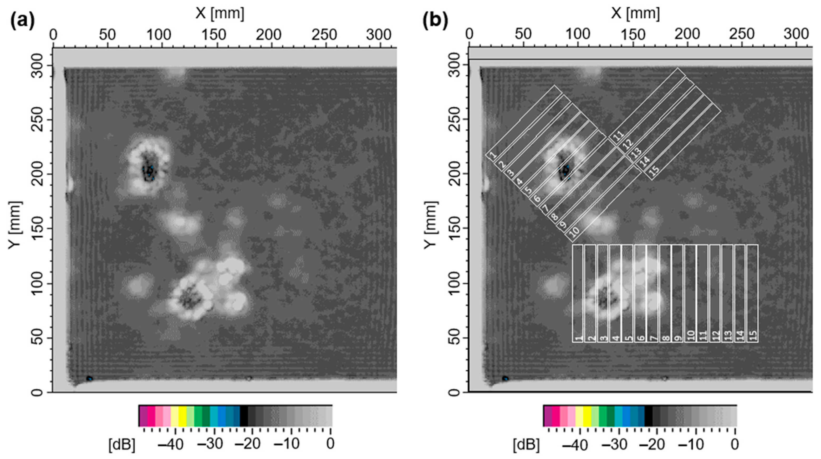
The amplitude-based C-scan image depicted in Figure 2a shows the left part of the Ox-CMC plate with a view field of 305 × 305 mm2. The local attenuation of the ultrasound signal is given as a heatmap in dB (logarithmic scale). Based on the attenuation level of the signals, a distinction can be made between undisturbed material of good quality, delaminations, and material gaps (e.g., matrix cracks or pore accumulations) [23]. The majority of the C-scan shows an undisturbed, homogeneous image of the material with an average attenuation of the ultrasound signal of about −17 dB and a narrow signal distribution, i.e., low variation in the attenuation. Two distinctly inhomogeneous areas with significant scattering and lower attenuation are visible in the upper left and lower center areas of the C-scan heatmap. A lower attenuation of the ultrasonic signal compared to the undisturbed material is typically linked to material gaps, whereas large area delaminations are typically characterized by a high attenuation of the ultrasound signal. On the basis of the C-scan map, two sample classes were defined with fiber orientation ±45° and 0/90°, which are commonly employed to assess the fiber- and matrix-dominated failure of CMC, respectively. From all areas of interest, bending bars were cut according to the cutting scheme overlaid in Figure 2b. Samples 1 to 10 of each class are located in the plate area with significantly scattering attenuation. Samples 11 to 15 of each class are located in areas of undisturbed material and act as the benchmark for subsequent analyses.

3.2. Characterization of Bending Bars

3.2.1. Resonant Frequency Damping Analysis

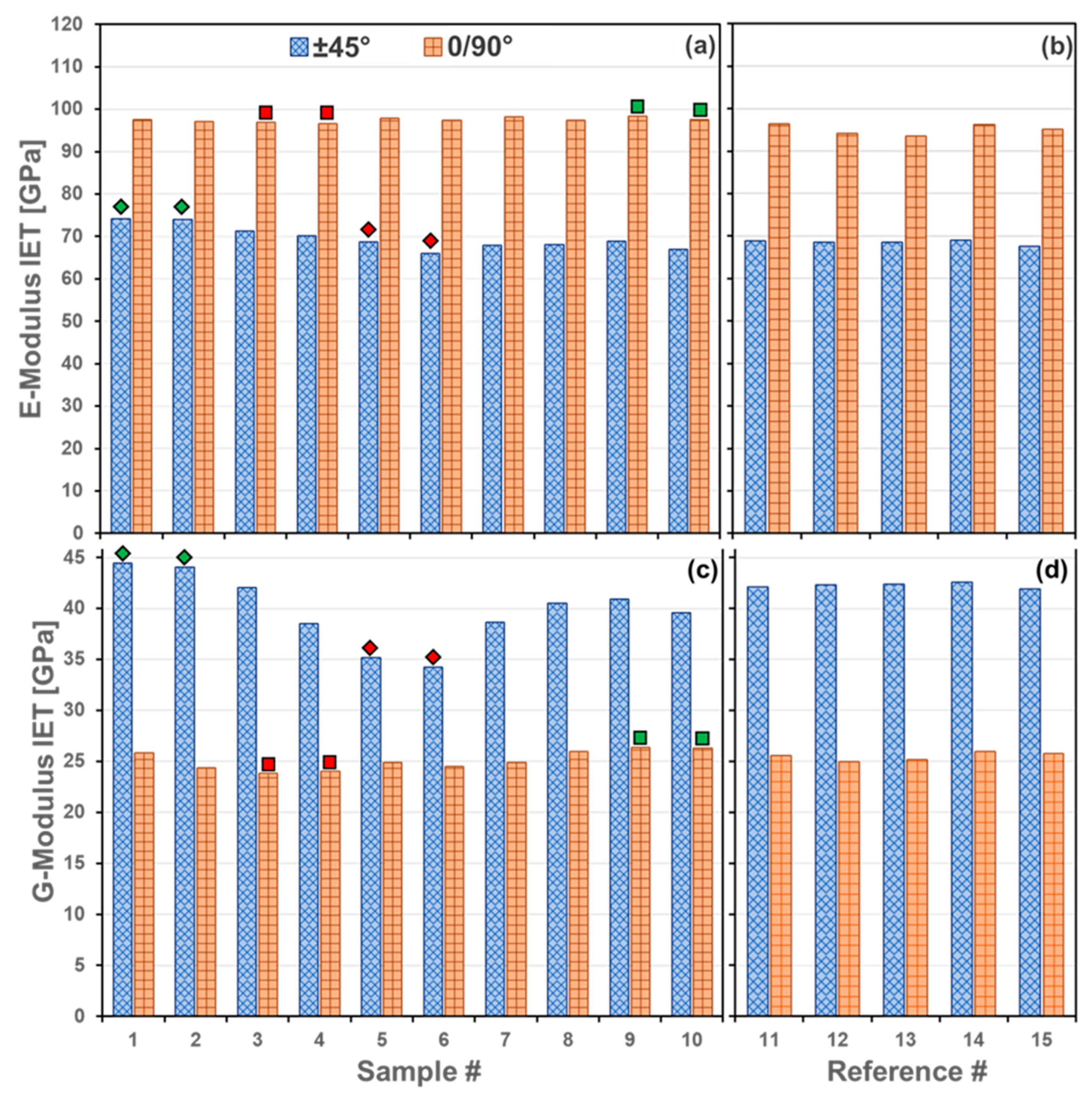
The first characterization method for the prepared samples was the resonant frequency damping analysis (RFDA), frequently referred to as impulse excitation technique (IET). The samples were measured in out-of-plane flexure and torsional vibration mode to determine the Young’s and G-Modulus. The measurement accuracy of the IET device is ±1.0 GPa for the Young’s modulus and ±0.3 GPa for the G-modulus for given sample dimensions. Figure 3 displays data of the ten bending bars cut from inhomogeneous CMC areas (left columns), together with the five reference samples (right columns). Evidently, the inhomogeneous areas show significant variations, in particular the E- and G-Moduli of ±45° samples (matrix dominated properties, cf. Table 1). Samples with 0/90° fiber orientation generally show a much lower scattering with the Young’s moduli within the measurement accuracy of ±1.0 GPa and a slight difference in the G-Moduli of 2 GPa (fiber dominated properties). Both datasets, in particular the ±45° direction, reflect well the visual observation from the ACU heatmap. Based on the IET results, a preselection was made for a subsequent CT examination. From both datasets, two characteristic samples with high and low E- and G-moduli were selected and marked with diamonds (±45°) and squares (0/90°), respectively. The color of filling is representative for high (green) and low (red) values. For example, sample #1 of the ±45° set shows highest values and sample #3 of the 0/90° set shows the lowest values. All further analyses were performed with special focus on these samples.

3.2.2. X-ray Computed Tomography Analysis

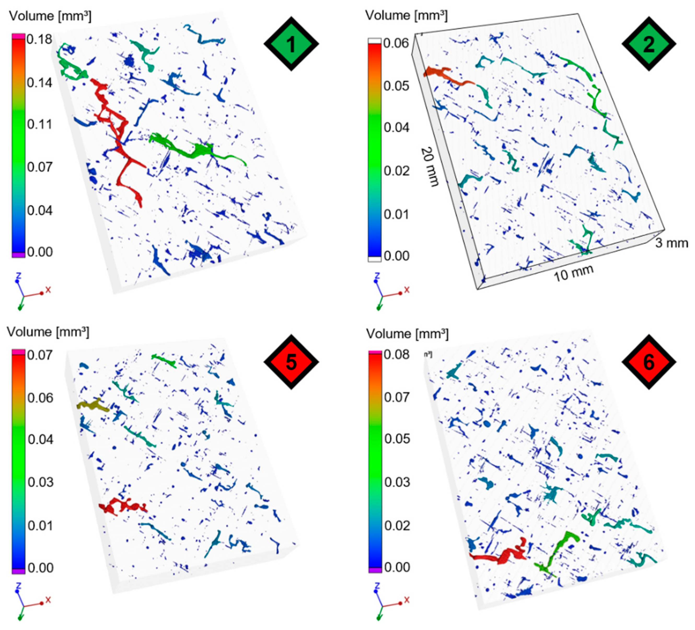
The microstructures of bending bars from homogenous and inhomogeneous areas according to the ACU-inspection were extracted and analyzed by µCT. Figure 4 shows the reconstructed 3-dimensional pore volume within specimens with fiber orientation of ±45°. Sample #1 and #2 were both cut from homogenous areas, #5 and #6 from inhomogeneous areas according to the ACU image in Figure 2. The pores between the fiber bundles are visible as elongated and tubular-like cavities throughout the laminate microstructure. Although few accumulations of pores (dark-red) can be detected, no significant difference between the four samples can be observed. The four bending specimens with orientation of 0/90° from homogenous (sample #9 and #10) and inhomogeneous (sample #3 and #4) areas were analyzed accordingly. The results are shown in Figure 5. Compared to the results of ±45°, the calculated pore volume of sample #9 and #10 is noticeably lower than the one of the samples from inhomogeneous area (sample #3), which is consistent with the observations of the ACU inspection.
The 3-dimensional pore volume was calculated based on detected pores at a voxel size of 12 µm3 divided by the investigated volume (see Table 2).
It is noteworthy that the reconstructed 3-dimensional pore volume is far off the 26.2% porosity measured by the Archimedes method for the investigated CMC-plate (cf. Table 2). Due to the voxel size of 12 µm3, smaller pores and especially the microporosity of the matrix phase are not detected in XCT.

3.2.3. Three-Point Flexural Tests

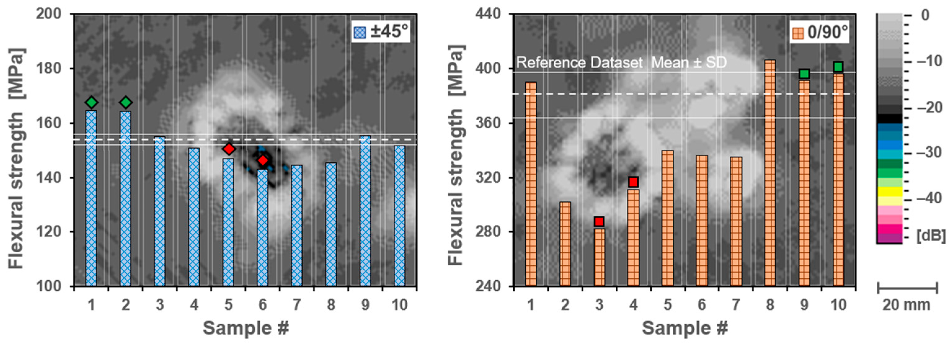
Figure 6 shows the flexural strength determined in three-point bending tests compared to the C-scan. In order to put the strength values of the individual samples (inhomogeneous area) in relation, the mean value of the reference dataset (homogeneous area) is plotted as a white dashed line with associated standard deviation (thin white lines). The samples from the inhomogeneous area clearly show a decrease in flexural strength. For both fiber orientations, the strength values of the individual samples with inhomogeneities are below the scatter band of the reference dataset. For ±45° fiber orientation, sample #6 has the lowest flexural strength at 143 MPa, which is 93% of the mean value of the reference samples. However, the effect is more evident for fiber orientation 0/90°. Sample #3 with 0/90° fiber orientation shows a flexural strength of 282 MPa which is 74% of the mean value of the reference samples. These observations are also reflected in the strain at flexural strength, again more dominant for fiber orientation 0/90° (see Table 1). Comparing the samples from inhomogeneous areas, no significant differences can be identified with regard to the flexural modulus. The reason for this might be that the flexural modulus is mainly influenced by the fiber reinforcement and only to a small amount by the porous matrix and the defects herein [24,25].

3.3. Correlation of ACU Heatmaps and Local Mechanical Properties

3.3.1. Data Extraction and Analyses

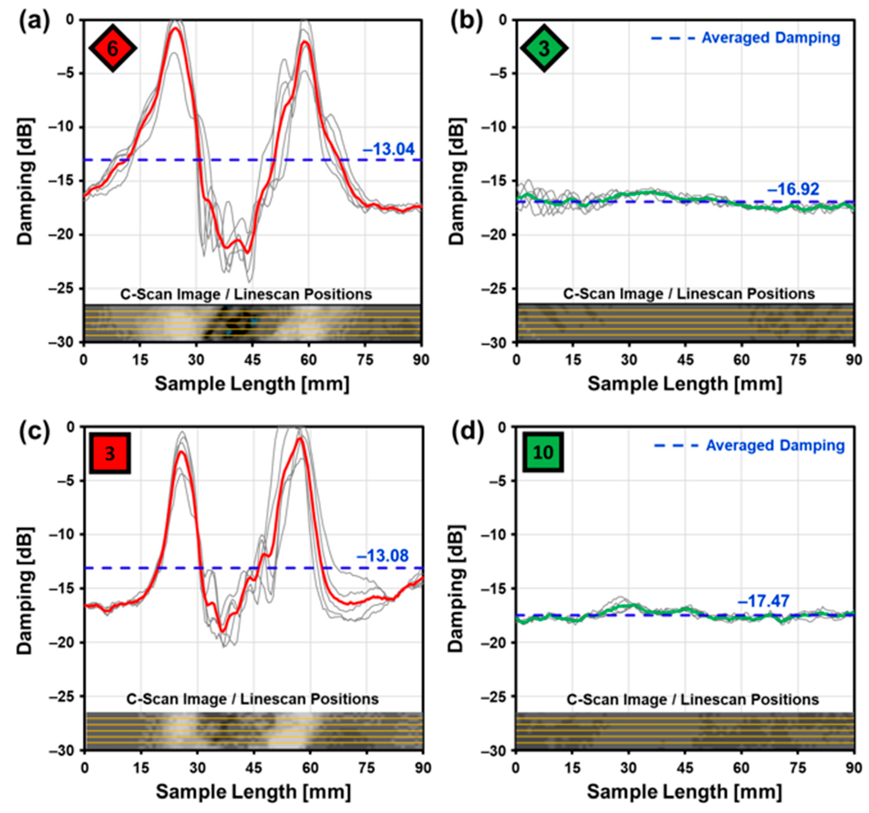
The employed ACU system yields 2D distribution maps of the acoustic damping of the current material as heatmap plots. A low scattering damping is considered as representative for ‘good’ or ‘strong’ and ‘homogeneous’ material. In the present case, ‘good’ material shows damping values of approximately −17 dB, see Figure 7b,d. For deeper analyses and understanding, however, meaningful damping values representing local effects are mandatory. Therefore, a routine was developed to extract comparable damping values for individual samples, i.e., bending bars. For this purpose, a Python-based script was developed to calculate line-data from the corresponding map areas. The concept is illustrated in Figure 7: for each bending bar, five parallel linescans were extracted (see thin grey lines and inset) and averaged (thick lines). In order to obtain a single damping value for the bending bars, damping data was averaged over the entire sample length (dashed lines). Figure 7a,b shows a comparison between ‘inhomogeneous’ sample #6 and ‘homogenous’ sample #3 selected from the ±45° set. An averaged damping of −13.04 dB was calculated for sample #6, i.e., about 23% less than the ‘homogenous’ sample #3. Similar values were extracted for bending bars #3 and #10 representing the 0/90° fiber orientation (see Figure 7c,d).
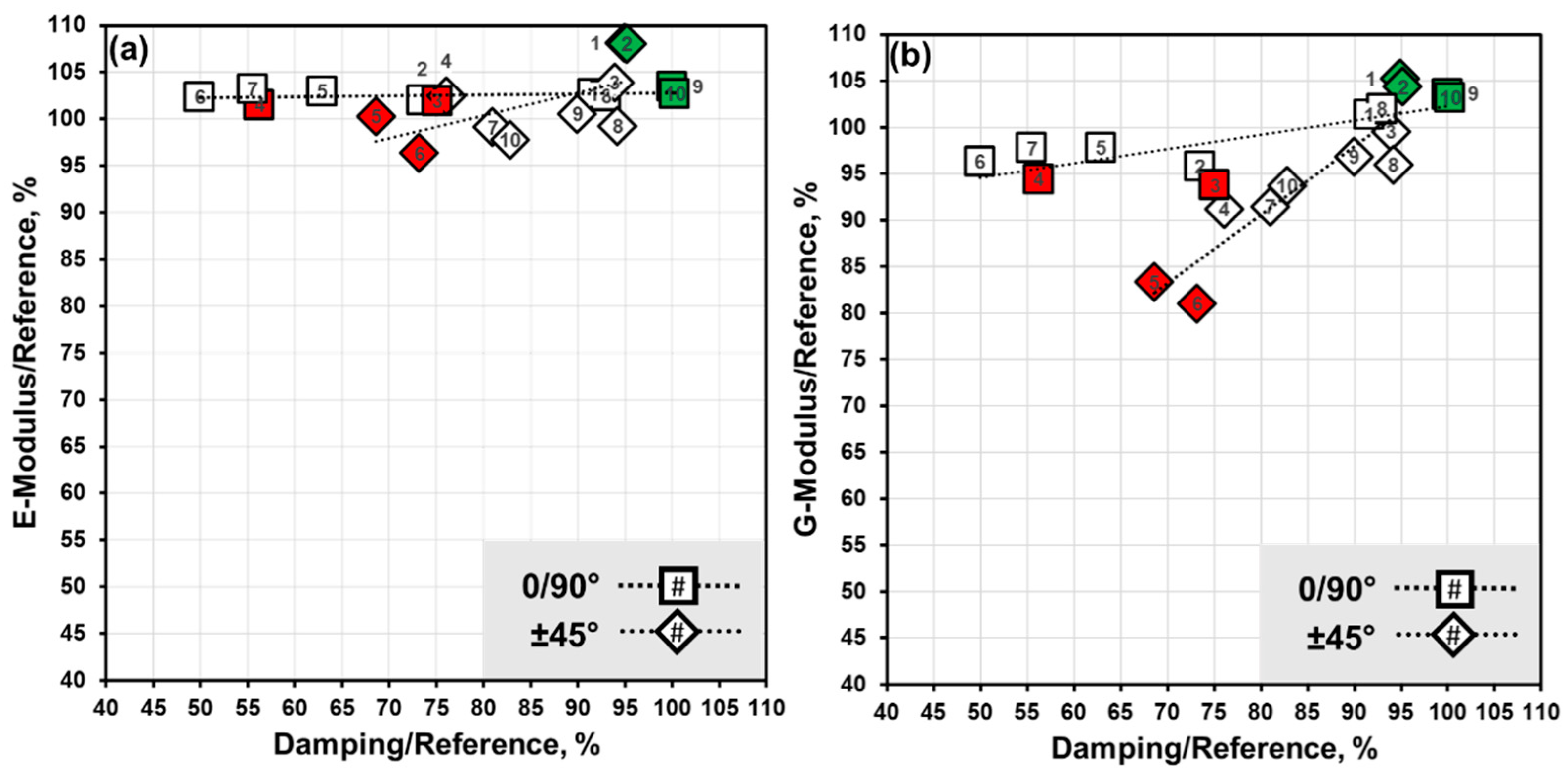
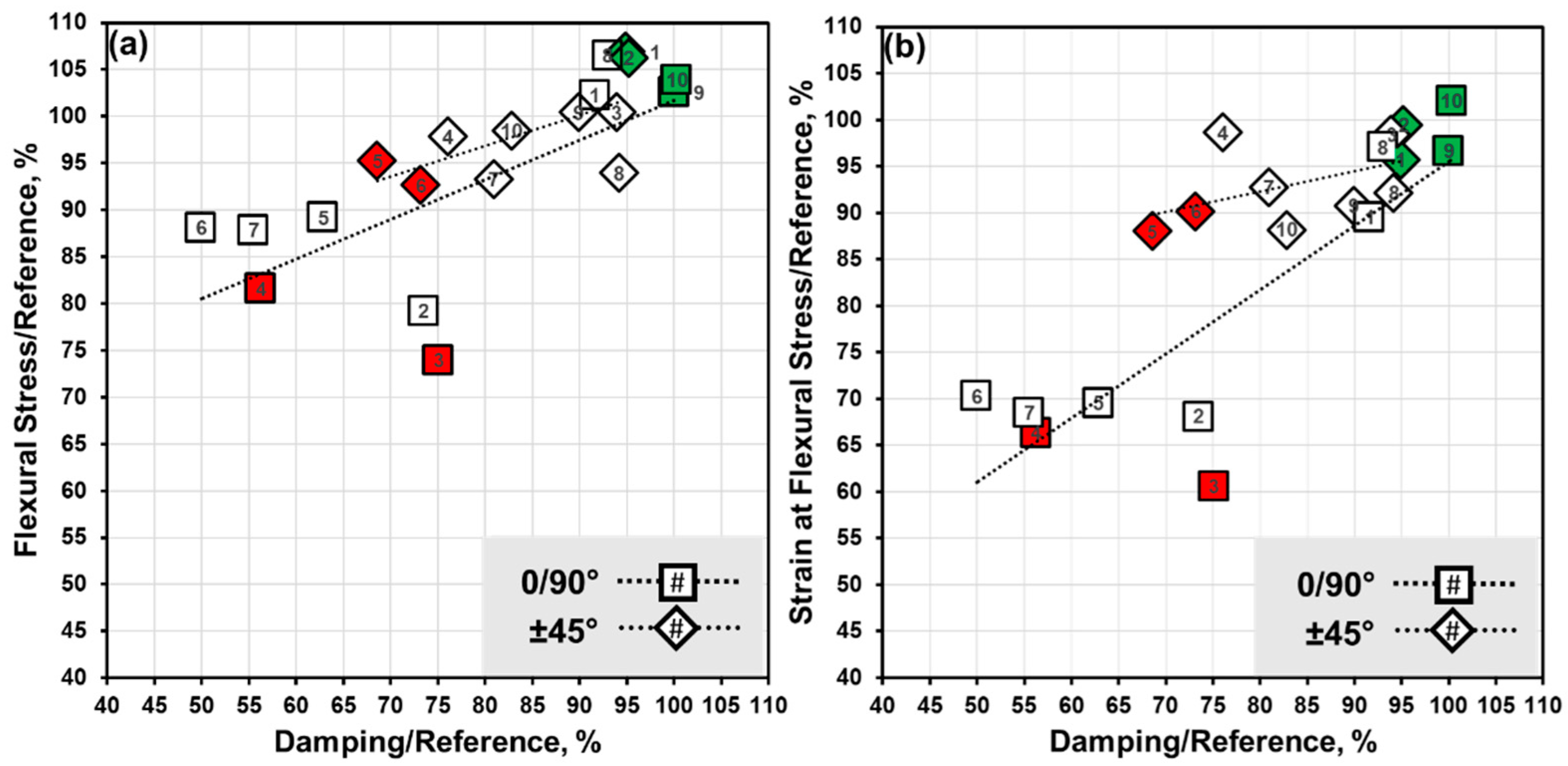
The objective was to identify quantifiable correlations between ACU results and CMC properties to obtain localized data for material quality at high 2D resolution. As a first step, the acquired data was analyzed for ‘homogeneous’ and ‘inhomogeneous’ regions in ‘bending bar resolution’. Assuming that homogenous regions in the ACU map are representative for good mechanical properties, the measured values and extracted damping data of the five samples for each ±45° and 0/90° fiber orientation were averaged and act as reference data. Data obtained from samples located in inhomogeneous areas are treated individually. All values were normalized and plotted against their corresponding reference values. As a hypothesis, a simple linear correlation between elastic/mechanical properties and ACU damping was assumed, and datapoints were fitted accordingly. In the following viewgraphs, the specific samples with low and high values as detected by RFDA (also analyzed by XCT) are highlighted by green or red filled marks, respectively (Note that each sample is marked by distinct symbols/indexes). First, relative elastic and shear moduli as derived from RFDA measurements are plotted against their relative damping. Evidently, both ±45° and 0/90° E-moduli derived from RFDA show little to no correlation to damping, as indicated by very low slopes of both linear fits (Figure 8a). On the other hand, irrespective of fiber orientation G-moduli show significant linear correlation to damping, but more pronounced in the case of ±45° fiber orientation (Figure 8b). With respect to bending strength, there is a linear correlation to damping in both fiber orientations, the fit curves also exhibit similar slopes (Figure 9a). With respect to strain at flexural strength, there is some ambiguity—while the 0/90° fiber orientation shows clearly distinguishable data following a linear trend, the datapoints of the orientation can be fitted linearly but with a relative low slope. In order to assess the quality of all linear fits, the parameters R2 along with an ANOVA-type analysis (confidence level > 95%) was calculated and compiled in Table 3. It tuns out that, besides both E-moduli linear fits, the strain at flexural strength linear fit for ±45° is also not significant, i.e., does not exhibit slopes sufficiently different from zero. The strongest linear correlation is found between sample damping and shear moduli, whereas bending strengths show significant, but generally weaker correlation. It must be emphasized, that ‘strong’ as well as ‘weak’ samples indexed by green/red filled symbols follow trends quite closely. Moreover, clustering into ‘good’ and ‘bad’ samples is seemingly possible, independent of the statistical evidence of linear approximations.

3.3.2. Supporting Microstructural Analysis

The observed inhomogeneities in the ACU maps are evidently correlated to local CMC material properties. The 2D resolution of ACU, however, is low, and microstructural features responsible for damping effects are presumably not detectable. Previous XCT analyses suggest that defects require high resolution imaging only provided by electron microscopy. In order to distinguish ‘strong’ and ‘weak’ samples, two cross sections were prepared for each fiber orientation with observation plane perpendicular to the long sample axes, respectively. The SEM images in Figure 10 prove that stronger samples 1 and 9 (upper row) exhibit much fewer small cracks than both ‘weak’ samples #5 and #3 in the lower row. Cracks are mainly aligned horizontally and are located at boundaries of fiber laminates or at matrix-rich regions. From this, it can be concluded that the main damage occurring in the investigated CMC plate is horizontal microcracking.

3.4. General View on the Employed Methodology

A synopsis of the analyses reveals significant as well as weak correlations of specific testing methods and material properties. XCT and the derived porosities did not reflect mechanical properties, i.e., higher measured porosity was not associated with lower flexural strength. ACU damping correlated well to RFDA analyses in case of Young’s and shear moduli for ±45°, i.e., matrix-dominated sample directions. On the other hand, in the fiber-dominated 0/90° direction, only a correlation of RFDA shear moduli and ACU damping could be found. Between ACU and 3-point bending tests, various significant correlations could be found: in particular flexural strengths were closely linked to measured local ACU damping. On the other hand, bending moduli could not be linked to local ACU damping. Combing these findings with SEM analyses of cross-sections, it can be stated that ACU mapping is highly sensitive to locally reduced flexural strengths and shear moduli of the investigated Ox-CMC samples caused by large-area (mm2) but thin (sub-µm) laminar matrix cracks. A great advantage of ACU could be the non-destructive detection of such flaws in large-scale specimen.

4. Conclusions

Air-coupled ultrasound mapping can be used to detect inhomogeneities in large Ox-CMC plates which are not easily detected by other NDT methods such as standard resolution XCT. Data retrieved from an Ox-CMC plate revealed significant correlations between local signal damping and specific mechanical properties. It appears that ACU is very sensitive to sub-micron horizontal microcracks and associated interlaminar properties, in particular shear moduli measured by resonant frequency damping analysis.
As the present findings were obtained from a single Ox-CMC plate only, i.e., a very limited sample count, further investigations are required to strengthen our database. In particular similar experiments regarding interlaminar shear strengths will be helpful for the validation of the concept. However, some uncertainty will inevitably remain as samples cut from ACU regions of interest can only be destructively tested once, i.e., either “in-plane” or “out-of-plane”. As the present study was performed with a planar Ox-CMC fabricated from woven fiber fabrics, the question remains still open if other processing methods and/or more complex geometries, such as filament-wound Ox-CMC tubes, can be accessed in a similar manner. In particular, the determination of site-specific mechanical properties from non-planar samples will presumably be challenging. In any case, the results obtained in this study appear to be a promising pathway to develop relatively straightforward, cost- and time-efficient quality assurance methods for Ox-CMC components. There is also a prospect for using ACU maps and corresponding mechanical properties as training datasets for automated quality assessment of CMC parts, as results indicate clear separation in ‘weak’ and ‘strong’ which can be very helpful for data clustering.

Author Contributions

Conceptualization and Methodology, J.R., P.M., Y.S. and R.J.; Investigation, J.R., F.F. and R.J.; Visualization, J.R., R.J. and P.M.; Writing—Original Draft Preparation, J.R., P.M. and Y.S.; Writing—Review and Editing, J.R., P.M., Y.S., R.J. and F.F. All authors have read and agreed to the published version of the manuscript.

Funding

This project has received funding from the Clean Sky 2 Joint Undertaking under the European Union’s Horizon 2020 research and innovation program and under grant agreement No. 686707.

Acknowledgments

Authors would like to thank E. Breitbarth (DLR Institute of Materials Research) for advice in software development, helpful discussion and feedback, and M. Welter (DLR Institute of Materials Research) for proofreading.

Conflicts of Interest

The authors declare no conflict of interest. The funders had no role in the design of the study; in the collection, analyses, or interpretation of data; in the writing of the manuscript, or in the decision to publish the results.

References

  1. Schmücker, M.; Mechnich, P. All-oxide ceramic matrix composites with porous matrices. In Ceramic Matrix Composites: Fiber Reinforced Ceramics and Their Applications; Krenkel, W., Ed.; Wiley-VCH: Weinheim, Germany, 2008; pp. 205–229. [Google Scholar]
  2. Newman, B.; Schäfer, W. Processing and Properties of Oxide/Oxide Composites for Industrial Applications. In High Temperature Ceramic Matrix Composites; Krenkel, W., Naslain, R., Schneider, H., Eds.; Wiley-VCH: Weinheim, Germany, 2001; pp. 600–609. [Google Scholar]
  3. Shi, Y.; Hönig, S.; Frieß, M.; Rüdinger, A.; Pritzkow, W.; Koch, D. Manufacture and characterization of oxide ceramic matrix composites out of commercial pre-impregnated fabrics. Ceram. Int. 2018, 44, 2320–2327. [Google Scholar] [CrossRef]
  4. Pritzkow, W.E.; Wehner, F.; Koch, D. Oxide Fiber Reinforced Oxide Ceramic Matrix Composite—An Alternative to Metallic Alloys at High Temperature. In Encyclopedia of Materials: Metals and Allloys; Caballero, F.G., Ed.; Elsevier: Oxford, UK, 2020; pp. 425–441. [Google Scholar]
  5. Pritzkow, W.E.; Almeida, R.S.; Mateus, L.B.; Tushtev, K.; Rezwan, K. All-oxide ceramic matrix composites (OCMC) based on low cost 3M Nextel™ 610 fabrics. J. Eur. Ceram. Soc. 2021, 41, 3177–3187. [Google Scholar] [CrossRef]
  6. Tushtev, K.; Martin Almeida, R.S. 5.5 Oxide/Ox-CMCs—Porous Matrix Composite Systems; Composites with Interface Coatings. In Comprehensive Composite Materials II; Beaumont, P.W., Zweben, C.H., Eds.; Elsevier: Oxford, UK, 2018; pp. 130–157. [Google Scholar]
  7. Keller, K.A.; Jefferson, G.; Kerans, R.J. Oxide-Oxide Composites. In Ceramic Matrix Composites: Materials, Modeling and Technology; Bansal, N.P., Lamon, J., Eds.; John Wiley & Sons: Hoboken, NJ, USA, 2014; pp. 236–272. [Google Scholar]
  8. Mechnich, P.; Welter, M. Porous Oxide Ceramic Matrix Composites—Properties, Manufacturing, and Applications. In Encyclopedia of Materials: Composites; Brabazon, D., Ed.; Elsevier: Oxford, UK, 2021; pp. 48–54. [Google Scholar]
  9. Ullmann, T.; Shi, Y.; Rahner, N.; Schmücker, M. Quality assurance for the manufacturing of oxide fiber reinforced ceramic composites for aerospace applications. In Proceedings of the 4th International Symposium on NDT in Aerospace, Augsburg, Germany, 13–15 November 2012; pp. 1–11. [Google Scholar]
  10. Ullmann, T.; Shi, Y.; Aoki, R. Capabilities of Lock-in Thermography for Non-destructive Inspection of Fibre Reinforced Composites. In Proceedings of the 11th International Conference on Quantitative InfraRed Thermography, Naples, Italy, 11–14 June 2012. [Google Scholar] [CrossRef]
  11. Asokkumar, A.; Jasiūnienė, E.; Raišutis, R.; Kažys, R.J. Comparison of Ultrasonic Non-Contact Air-Coupled Techniques for Characterization of Impact-Type Defects in Pultruded GFRP Composites. Materials 2021, 14, 1058. [Google Scholar] [CrossRef] [PubMed]
  12. Schmidt, T.; Dutta, S.; Ullmann, T. Production integrated NDT by means of automated Thermography. In Proceedings of the 2012 International Conference on Quantitative InfraRed Thermography, Naples, Italy, 11–14 June 2012; Cardone, G., Ed.; NDT.net: Rheinland-Pfalz, Germany, 2012. [Google Scholar] [CrossRef]
  13. Huber, A. Non-destructive testing of future rocket boosters using air-coupled ultrasound. In Proceedings of the 19th World Conference of Non-Destructive Testing, Munich, Germany, 13–17 June 2016; pp. 1–9. [Google Scholar]
  14. Schönheits, M.; Huber, A.; Gänswürger, P. Air-coupled Ultrasonic Inspection with Adaptive Lamb Wave Control. In Proceedings of the 16th International Conference on Informatics in Control, Automation and Robotics, 2nd ed.; Gusikhin, O., Madani, K., Zytoon, J., Eds.; Science and Technology Publications: Prague, Czech Republic, 2019; pp. 430–438. [Google Scholar]
  15. Neuenschwander, J.; Furrer, R.; Roemmeler, A. Application of air-coupled ultrasonics for the characterization of polymer and polymer-matrix composite samples. Polym. Test. 2016, 56, 379–386. [Google Scholar] [CrossRef]
  16. Kudela, P.; Radzienski, M.; Ostachowicz, W. Impact induced damage assessment by means of Lamb wave image processing. Mech. Syst. Signal Process. 2018, 102, 23–36. [Google Scholar] [CrossRef]
  17. Laureti, S.; Rizwan, M.K.; Malekmohammadi, H.; Burrascano, P.; Natali, M.; Torre, L.; Rallini, M.; Puri, I.; Hutchins, D.; Ricci, M. Delamination Detection in Polymeric Ablative Materials Using Pulse-Compression Thermography and Air-Coupled Ultrasound. Sensors 2019, 19, 2198. [Google Scholar] [CrossRef] [PubMed] [Green Version]
  18. Panda, R.S.; Rajagopal, P.; Balasubramaniam, K. Characterization of delamination-type damages in composite laminates using guided wave visualization and air-coupled ultrasound. Struct. Health Monit. 2017, 16, 142–152. [Google Scholar] [CrossRef]
  19. Schmelt, A.S.; Marhenke, T.; Hasener, J.; Twiefel, J. Investigation and Enhancement of the Detectability of Flaws with a Coarse Measuring Grid and Air Coupled Ultrasound for NDT of Panel Materials Using the Re-Radiation Method. Appl. Sci. 2020, 10, 1155. [Google Scholar] [CrossRef] [Green Version]
  20. Quattrocchi, A.; Freni, F.; Montanini, R. Air-coupled ultrasonic testing to estimate internal defects in composite panels used for boats and luxury yachts. Int. J. Interact. Des. Manuf. 2020, 14, 35–41. [Google Scholar] [CrossRef]
  21. Bustamante, L.; Jeyaprakash, N.; Yang, C.-H. Evaluation of Defect Detection in Aluminium, CFRP and Epoxy Resin Plates Using Non-contact Air-Coupled Ultrasonic Waves. Int. J. Precis. Eng. Manuf. 2020, 21, 1843–1856. [Google Scholar] [CrossRef]
  22. Yilmaz, B.; Asokkumar, A.; Jasiūnienė, E.; Kažys, R.J. Air-Coupled, Contact, and Immersion Ultrasonic Non-Destructive Testing: Comparison for Bonding Quality Evaluation. Appl. Sci. 2020, 10, 6757. [Google Scholar] [CrossRef]
  23. Vasechko, V.; Schmücker, M.; Rahner, N.; Ullmann, T. Air-Coupled Ultrasonic Inspection Technique as NDT Tool for Evaluation of Porous Wound Oxide/Oxide Composite Ceramics. In Proceedings of the 19th World Conference of Non-Destructive Testing, Munich, Germany, 13–17 June 2016; pp. 1–9. [Google Scholar]
  24. Zok, F.W.; Levi, C.G. Mechanical Properties of Porous-Matrix Ceramic Composites. Adv. Eng. Mater. 2001, 3, 15–23. [Google Scholar] [CrossRef]
  25. Puchegger, S.; Loidl, D.; Peterlik, H.; Kromp, K. Determination of Elastic Modules in Dependence on Orientation by the Resonant Beam Technique. In Advanced Materials Forum III; Vilarinho, P.M., Ed.; Trans Tech Publications: Zürich, Switzerland, 2006; pp. 815–824. [Google Scholar]
Figure 1. Schematic of the experimental methodology.
Jcs 05 00286 g001
Figure 2. (a) C-image of the ACU-inspection with two distinct inhomogeneous plate regions; (b) C-image with overlaid cutting scheme for samples with fiber orientation ±45° and 0/90°.
Jcs 05 00286 g002
Figure 3. Young’s and shear modulus of bending bars determined using the impulse excitation technique. Marked samples were selected for further examination in XCT and SEM. (a,c) Samples from inhomogeneous areas of the C-scan. (b,d) Reference samples from homogeneous areas of the C-scan.
Jcs 05 00286 g003
Figure 4. µCT analysis of calculated local pore volume and its distribution in the center area of bending specimen with fiber orientation of ±45°, sample #1 and #2 from homogeneous area, sample #5 and #6 from inhomogeneous area.
Jcs 05 00286 g004
Figure 5. µCT analysis of calculated local pore volume and its distribution in the center area of bending specimen with fiber orientation of 0/90°, sample #9 and #10 from homogeneous area, sample #3 and #4 from inhomogeneous area.
Jcs 05 00286 g005
Figure 6. Flexural strength determined in three-point bending test in comparison to the C-scan image. The flexural strength mean value (dashed white line) of the reference samples with associated standard deviation (thin white line). Samples with variation in local damping show a decrease in flexural strength.
Jcs 05 00286 g006
Figure 7. Damping curves extracted from the ACU raw data using the Python-based script. Inset displays the sample C-scan with linescan positions (yellow lines). Damping curves are shown as grey lines in the diagram and in averaged form as red/green line. The dashed line shows the average value over the entire sample length. Samples with fiber orientation ±45° (upper row) and 0/90° (lower row) from inhomogeneous (a,c) and homogenous region (b,d) of the C-scan.
Jcs 05 00286 g007
Figure 8. Correlation of E- (a) and G-moduli (b) and average ACU damping of bending bars (relative to reference samples). No significant correlation is found for E-moduli irrespective of sample orientation (a) whereas G-moduli are correlated to ACU damping only for ±45°samples (b).
Jcs 05 00286 g008
Figure 9. Correlation of flexural stresses (a) and strains (b) to average ACU damping of bending bars (relative values). A significant correlation is found irrespective of sample orientation (a), whereas strains are correlated to ACU damping only for 0/90°samples (b).
Jcs 05 00286 g009
Figure 10. SEM-cross sections of characteristic samples show the quasi crack-free microstructures of ‘stronger’ samples #1 (±45° cut) and #9 (0/90° cut) (upper row) compared to ‘weaker’ samples #5 and #3 which display small microcracks mostly aligned parallel to fiber fabric laminates.
Jcs 05 00286 g010
Table 1. Summary of experimental properties determined using impulse excitation technique and three-point bending test.
Specimen
No.
Geom.
Density
(g/cm3)
Impulse Excitation Technique3-Point Bending Test
Young’s
Modulus
(GPa)
Shear
Modulus
(GPa)
Flexural
Strength
(MPa)
Strain at
Flexural Strength
%
Bending
Modulus
(GPa)
Fiber Orientation ± 45° Samples
13.0374451650.48771
23.0374441640.50664
33.0371421550.50173
43.0170391510.50267
52.9869351470.44869
62.9766341430.45968
72.9968391440.47268
83.0068411450.46969
92.9969411550.46274
102.9767401520.44975
Mean ± SD3.00 ± 0.0370 ± 340 ± 3.4152 ± 80.476 ± 0.02270 ± 3
112.9869421550.51662
122.9769421560.51167
132.9769421560.52465
142.9869431510.48765
152.9668421530.50867
Mean ± SD2.97 ± 0.0169 ± 142 ± 0.3154 ± 20.509 ± 0.01465 ± 2
Fiber Orientation 0/90° Samples
13.0098263900.498100
23.0097243020.37997
32.9997242820.33795
42.9997243110.369102
53.0098253400.387100
63.0097253360.39196
73.0098253350.38197
82.9998264060.540101
92.9999263910.538100
103.0098263960.56896
Mean ± SD3.00 ± 0.0197 ± 125 ± 0.9349 ± 440.439 ± 0.08798 ± 3
112.9896263980.59094
122.9694253870.54894
132.9694253860.59690
142.9896263540.50492
152.9795263820.54597
Mean ± SD2.97 ± 0.0195 ± 125 ± 0.4381 ± 160.557 ± 0.03893 ± 3
Table 2. Pore volume calculated from XCT data.
Fiber Orientation ± 45° SamplesFiber Orientation 0/90° Samples
Specimen No.Calc. Pore Volume, %Specimen No.Calc. Pore Volume, %
10.2390.07
20.39100.17
50.2830.38
60.2540.08
Specimen No. 1, 2, 9, 10 from homogeneous and 3, 4, 5, 6 from inhomogeneous area of the C-scan.
Table 3. ANOVA-type analysis with R2 parameters.
Linear Regression
R2/ANOVA F-Values
E-ModulusG-ModulusFlexural StrengthStrain at Flexural Strength
±45° Samples0.363/4.557 *0.853/46.2520.423/5.8730.257/2.773 *
0/90° Samples0.108/0.969 *0.650/14.8530.501/8.0630.733/21.947
* Slope of linear fit NOT significantly different from ZERO (95% confidence level).
Publisher’s Note: MDPI stays neutral with regard to jurisdictional claims in published maps and institutional affiliations.