Article

Additive Manufacturing of Carbon Fiber Reinforced Plastic Composites: The Effect of Fiber Content on Compressive Properties

1
Department of Industrial, Manufacturing and Systems Engineering, Texas Tech University, Lubbock, TX 79409, USA
2
Department of Physics, Eberhard Karl University of Tubingen, 72076 Tübingen, Germany
*
Author to whom correspondence should be addressed.
J. Compos. Sci. 2021, 5(12), 325; https://doi.org/10.3390/jcs5120325
Submission received: 1 December 2021 / Revised: 10 December 2021 / Accepted: 14 December 2021 / Published: 16 December 2021
(This article belongs to the Special Issue Carbon Fiber Composites)

Abstract

:
The additive manufacturing (AM) of carbon fiber reinforced plastic (CFRP) composites continue to grow due to the attractive strength-to-weight and modulus-to-weight ratios afforded by the composites combined with the ease of processibility achievable through the AM technique. Short fiber design factors such as fiber content effects have been shown to play determinant roles in the mechanical performance of AM fabricated CFRP composites. However, this has only been investigated for tensile and flexural properties, with no investigations to date on compressive properties effects of fiber content. This study examined the axial and transverse compressive properties of AM fabricated CFRP composites by testing CF-ABS with fiber contents from 0%, 10%, 20%, and 30% for samples printed in the axial and transverse build orientations, and for axial tensile in comparison to the axial compression properties. The results were that increasing carbon fiber content for the short-fiber thermoplastic CFRP composites slightly reduced compressive strength and modulus. However, it increased ductility and toughness. The 20% carbon fiber content provided the overall content with the most decent compressive properties for the 0–30% content studied. The AM fabricated composite demonstrates a generally higher compressive property than tensile property because of the higher plastic deformation ability which characterizes compression loaded parts, which were observed from the different failure modes.

1. Introduction

1.1. Additive Manufacturing of Carbon Fiber Composites

Developments in additive manufacturing (AM) of carbon fiber reinforced plastic (CFRP) composites continue to grow because of their increasing acceptance as alternatives to metallic materials in several applications, mainly due to their attractive strength-to-weight and modulus-to-weight ratios [1]. They also benefit from easier processability and manufacturing flexibilities because of their lower melting temperatures, which are usually high enough to meet operational temperature requirements and low enough for flexible manufacturing outside of dedicated facilities [2]. Recent developments in the AM of CFRP composites are leading to increasing applications, especially where material or fabrication methods were not previously available or are more complicated [3,4].
Synthetic fibers provide the bulk of the short fibers used as reinforcement materials in the AM fabrication of FRP composites due to their superior mechanical properties and thermal stability over natural fibers [1]. Short fibers are preferred to continuous fibers in certain AM applications because of the ease of fabrication into intricate shapes while still providing improved mechanical properties. Carbon fibers make up most of these short-fiber applications followed by glass fiber (GF) and Kevlar fiber. The carbon fibers are preferred because of their higher strength, stiffness, chemical resistance, and thermal stability, etc., and are by itself is the strongest and stiffest synthetic fiber, with a strength-to-weight ratio nearly twice that of 6061 Aluminum [5].
Various investigations on the AM fabrication of FRP composites concluded on the higher mechanical and thermal preference of carbon fibers over the other synthetic fibers. Goh et al. [6] in the characterization of the mechanical properties of AM fabricated CFRP and GFRP reported higher tensile strength and modulus for CFRP composite at 600 MPa and 13.0 GPa, respectively, whereas the glass fiber was 450 MPa and 7.2 GPa, respectively. They also obtained higher flexural properties where the carbon-fiber-reinforced-plastic (CFRP) composite showed almost triple that of the glass-fiber-reinforced-plastic (GFRP) composite. Zhang et al. [7] in their evaluation of the bond strength of printed acrylonitrile-butadiene-styrene (ABS), carbon nanotube-reinforced ABS (CNT-ABS), and short carbon-fiber-reinforced ABS (CF-ABS) samples found the printed CF-ABS to offer better tensile strength and modulus than the CNT-ABS and pure ABS for most of the print orientations. Ning et al. [8] compared graphite (GR) flakes as alternative reinforcement instead of chopped fibers and the result were that the AM fabricated CF-ABS exhibited better tensile properties than GR-ABS composite parts, even though the GRFP may offer less porosity. The reason they claimed was that the carbon fiber has a much higher aspect ratio which allows for better interfacial bonding compared to the graphite. Mohammadizadeh and Fidan [9] reported on the higher thermomechanical properties of AM fabricated carbon-fiber-reinforced Nylon compared to glass-fiber and Kevlar reinforced, where their Dynamic Mechanical Analysis results showed the highest properties improvement under 150 °C for the carbon-fiber-reinforced Nylon over the other fiber-reinforced composites.
A highlight of the use of thermoplastic CFRP composites is their ease of processability, repairability, and maintenance offering compared to their thermoset versions which are more difficult to repair. Their physical state reversibility on the application of processing temperatures often allows for easier service repairability and recyclability which makes them preferred whenever they meet process requirements [10]. Tekinalp et al. [11] described the thermoplastic matrixes’ relatively high melt viscosities as translating to rapid manufacturing, reparability, recyclability, and significant cost reductions. Hence, the justification for more understanding of AM fabricated CFRP composites from conducting this investigation to determine the effects of fiber content on the compressive properties.

1.2. Compressive Properties of AM Fabricated CFRP Composites

Observing short fiber design factors has been shown to improve the mechanical properties of CFRP composites. Material factors such as fiber content [12,13,14], fiber orientation [12], fiber length [13], aspect ratio, fiber-diameter, fiber-matrix adhesion [7], etc. have been reported as major contributors to mechanical performance. However, in studying these, only the tensile properties improvements have been the hallmark of AM fabricated CFRP investigations, with the comprehension of compressive properties still lagging. Table 1 shows the investigations conducted to date on the compressive properties of short fiber AM fabricated CFRP composites, but still no investigations on fiber content effects on compressive properties.
Understanding the effect of carbon fiber content on compressive properties is important to the sustainable application of short fiber AM fabricated CFRP composites in applications such as wind energy, where they have been used to fabricate wind turbine molds and are currently being explored to fabricate turbine components [15,16]. Such components operate at different times under static and dynamic loading, where they are subjected to a combination of compressive and tensile stresses. Other applications such as aerospace trim tools, hand layup tools, and vacuum-assisted resin transfer (VARTM) tools made from short fiber AM fabricated CFRP composites which are subjected to some forms of compressive stresses have also been proposed [17,18]. Table 1 shows the limited investigations conducted so far on the compressive properties of short fiber thermoplastic AM fabricated CFRP composites, with missing reports on fiber content effects.
Table 1. Summary of Reported Investigations on the Compressive Properties of AM Fabricated CFRP Composites.
Short Fiber CFRP SampleInvestigationsCarbon Fiber Content (%)Maximum Tensile Strength (Mpa)Author
CF-ABSMicrostructural Evaluation through X-ray CT Technique1567.0[19,20]
CF-ABSChopped CF-ABS20%N/A[21]
CF-PAChopped CF-ABSN/A101[22]
To date, the only four reported investigations on the compressive properties of short fiber AM fabricated CFRP composites did not investigate the fiber content effects [19,20,21,22]. Quan et al. tested at different strain levels the damage evolution of short fiber AM fabricated under compression loading using the X-ray CT technique. They also investigated the compressive behavior of 3D orthogonal short fiber AM fabricated CFRP composites and that of its silicone infused composite to demonstrate the feasibility of AM fabricated 3D orthogonal preform. Meraz et al. analyzed the compressive and rheology properties of AM fabricated CFRP composites in which they used optical imaging to create a relationship effect of scanning strategies and printing temperatures on the compressive behaviors of 3D Printed polyamide (PA) based composites. Wang et al. [22] considered the effects of printing temperature and orientations on the compressive properties of AM fabricated CF-PA composites but did not test the effect of fiber content.
Other investigations also either addressed pure thermoplastics or continuous fiber-reinforced composites. Lee et al. [23] reported the anisotropic compressive strength of AM fabricated thermoplastics but did not consider the effects of short fiber content composition. M. Araya-Calvo et al. [24] investigated the effect of continuous fiber content on CF-PA6 but did not address short carbon fibers. They explained the effects of reinforcement pattern, reinforcement distribution, print orientation, and percentage of fiber on the compressive properties and claimed optimum compressive stress and modulus at 24% fiber reinforcement. However, this was reported for continuous fibers. J. Chacon et al. [24] investigated 59.2% continuous fiber CF-PA6, which also did not address short carbon fibers.
Previous investigations which addressed short fiber content only considered tensile and flexural properties but not compressive properties. Tekinalp et al. [12] evaluated highly oriented CF-ABS composites up to 40% carbon fiber wt.% and reported tensile strength and modulus to increase by up to 115% and 700%, respectively. Ning et al. [13] investigated the effect of carbon fiber wt.% up to 15% in ABS, with the conclusion that adding carbon fiber would increase the tensile strength and modulus but decrease toughness and ductility. Duty et al. [14] investigated carbon fiber content effects on tensile properties in which they reported improvements in the CF-ABS tensile strength and modulus up to ~60 MPa and ~12 GPa, respectively, but with some degree of anisotropy. Love et al. [25] investigated 13% short fiber AM fabricated CFRP composite in which they claimed the addition of carbon fiber to a thermoplastic matrix significantly increases the strength, stiffness, and thermal conductivity, and greatly reduced the distortion of the parts. However, these only addressed tensile and flexural properties.

1.3. Research Motivations

The current state of knowledge has only addressed short carbon fiber content effects in the tensile and flexural modes, but no reported investigations in the compressive mode. It is important to conduct this study to understand how compressive properties fill in the research gap of mechanical performance improvements with carbon fiber additions to thermoplastic matrixes for AM composite applications. The study will help to rule out any possible bias from the general hypothesis that increasing carbon fiber content in short fiber AM fabricated CFRP composites should improve material compressive properties. It will also help to make more technically sound judgments on materials selection decisions that may arise for applications where parts are subjected to a combination of tensile and compression loading.

2. Materials and Methods

2.1. AM Workpiece Fabrication Procedure

2.1.1. Material Compounding and Filamenting

Chopped carbon fiber averaging 7 µm average diameter and 150 µm length (Pantex 30, Zoltek, St. Louis, MO, USA) and MG94 natural ABS pellets (Filastruder, Snellville, GA, USA) was used to fabricate the samples. The 10%, 20%, and 30% fiber contents were compounded with the ABS pellets by melt mixing in a twin-screw Prep-Center Mixer (CWB Brabender Instruments Inc., Duisburg, Germany), with the working temperature and rotor speed set to 220 °C and 60 rpm, respectively, for one hour to ensure stable temperature and speed before introducing the carbon fiber. The thermoplastic fraction of the composite was first introduced into the mixer and allowed to maintain the glass transition phase for 5 min before the carbon fiber fraction was added, and subsequently melt-mixed for another 7 min for effective compounding. The compounded mixture was then removed from the hopper and allowed to cool for 30 min after which they were crushed into smaller bits using a Pelletizer (Fritsch, Idar-Oberstein, Germany). The same process was repeated for each of the 10%, 20%, and 30% carbon fiber content compositions. The pelletized composite contents were made individually made into filaments using a filamenting extruder machine (Felfil Evo, Turin, Italy), with a single screw extruder of 1.75 mm Die-head with the temperature set to 220 °C and speed at 7 rpm. Figure 1 illustrates the sample fabrication process.

2.1.2. Fabricated Workpiece

A Fused Deposition Modelling (FDM) 3D printer (Prusa Mk3 i3, Prague, Czech Republic), with a modified enclosure system (Creality 3D, Shenzhen, China) to control the temperature to 45 ± 5 °C and relative humidity to less than 25% RH was used to fabricate the CFRP composite compression and tensile workpieces. The modified printing setup was influenced by studies that reported that controlling temperature within a printing chamber reduces porosity and improves material properties [26]. Table 2 lists the printing parameters used to fabricate the test samples, some of which were determined from reported studies [22,27]. The compression samples illustrated in Figure 2a,b consist of the axial and transverse orientations printed as 25.4 mm × 12.7 mm (height × diameter) dimensions, respectively, while Figure 2c illustrates the axial tensile orientation printed as 165 mm × 13 mm × 3.2 mm (length × width × thickness). The axial axis is printed parallel to the gage section of the sample while the transverse axis is printed perpendicular to the gage.

2.2. Measurement Procedure

Axial and transverse compression (ASTM D695) [28] and axial tensile (ASTM D638) [29] samples consisting of five workpieces each were tested at the normal ambient condition to determine the effects of carbon fiber content on the compressive properties in comparison to the already established tensile properties for AM fabricated CFRP composites. The compression samples tested 0%, 10%, 20%, and 30% carbon fiber contents, while the tensile was only able to test 0%, 10%, and 20% carbon fiber contents because of the difficulty of processing tensile samples beyond 20% content. Mechanical testing was conducted using a universal test machine (AGS-J, Shimadzu Co., Kyoto, Japan) with a 100 kN load cell fixture for the compression at a test speed of 1.3 mm/s and a 10 kN for the tensile at a test speed of 5.0 mm/s. Figure 3 shows the mechanical test setup and the quality of the fabricated workpieces.
The strength, ductility, modulus, and toughness values were determined from the plot of the stress-strain curves using the Origin pro graphing and analysis software. The compressive strength was determined from an average of maximum stress values from the plots of four test specimens. The compressive modulus was calculated from the ratio of initial stress to the corresponding strain. The modulus values were specifically determined from the slope of the tangent to the elastic region of the curve from the (0,0) origin. The ductility values were determined as the strain values at the maximum strength, while the toughness values were determined from the area under the stress-strain curve using the integration function under the ‘peak and baseline’ tab of the software. Microscopic evaluation of the ABS and CFRP composite compressive and tensile specimens were examined at 1000× magnifications using a Scanning Electron Microscope (Thermo Fisher Phenon XL, Waltham, MA, USA) to determine the influence of carbon fiber on the failure mode of the composites.

3. Results

The result evaluated the compressive and tensile properties of AM fabricated CFRP composites comparing 0% (ABS), 10%, 20%, and 30% carbon fiber contents. This was used to establish the effect of fiber content on the compressive strength, modulus, ductility, and toughness and to compare compressive to tensile properties.

3.1. Compressive Properties

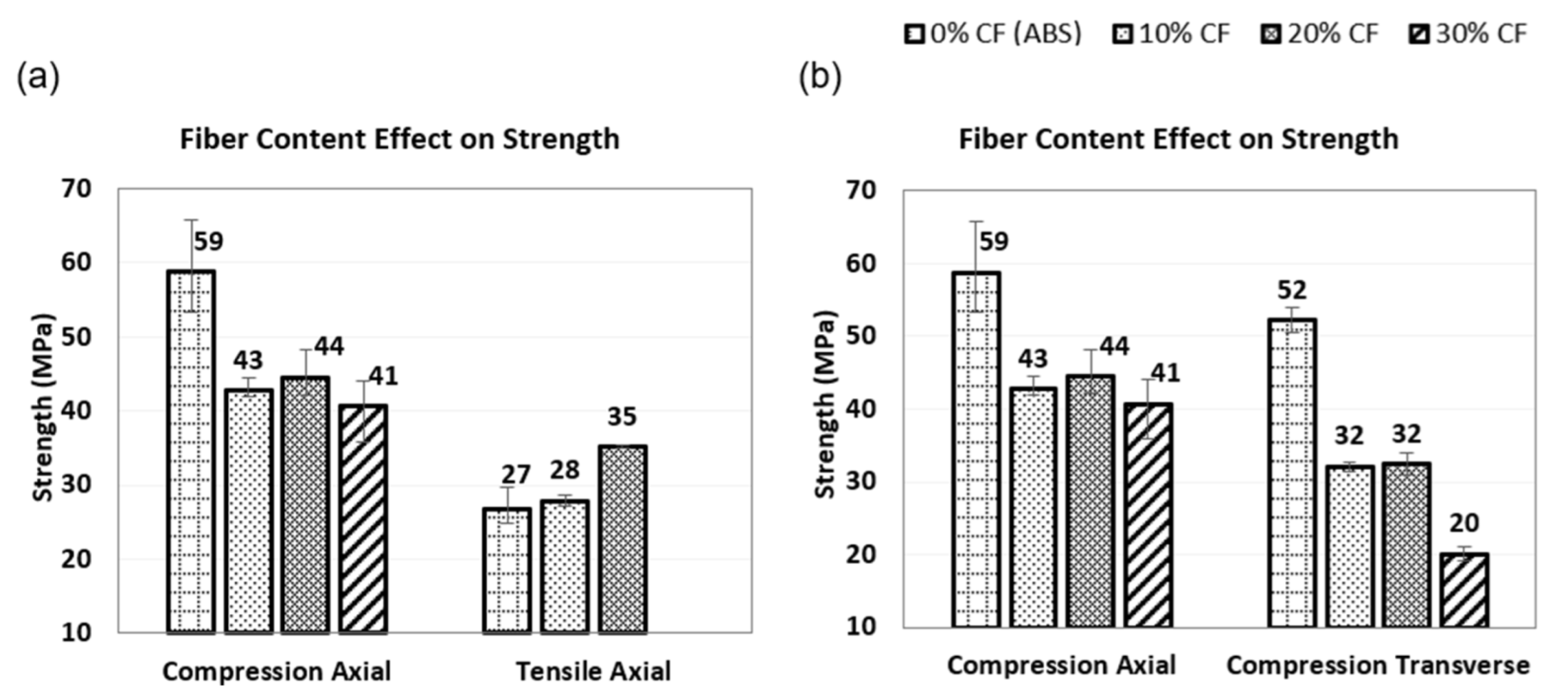
3.1.1. Compressive Strength

The material compressive strength measures the maximum stress that can be applied before the materials buckling failure. Figure 4a shows the comparison of the compressive strength across the axial and transverse axes of the composites, while Figure 4b shows the comparison of the axial compressive and axial tensile strength.
As seen in Figure 4a, the AM fabricated composite exhibited higher compressive than tensile strength from the plastic deformation characteristics in the compressive mode against elastic deformation which is typical of the tensile mode. The plastic deformation more easily redistributes stress at existing flaws, thus, limiting crack propagation which often fails at lower strengths. However, unlike the tensile strength which reported improved strength with increasing fiber content, the compression reported reduced strength. A 27% strength reduction across the axial axis of the composite was observed for the 10–20% fiber content, while a reduction by up to 31% was observed for the 30% fiber content. Larger strength reduction was observed across the transverse axis where a reduction up to 38% was observed for the 10–20% fiber content and up to a 62% reduction for the 30% content.
A comparison of compressive strength across the axial and transverse axes for up to 30% carbon fiber content as seen in Figure 4b showed the composite exhibiting higher strength in the axial than in the transverse axis like reported investigations for the tensile mode [14,30]. This is because of the better bonding across the continuous print bead which characterizes the axial axis versus the interlayer stacking which characterizes the transverse axis of AM prints. It is interesting to note the increasing anisotropy (differences in the compressive strength) across the axial and transverse axis with increasing carbon fiber content, which is important to understand the optimal mechanical performance of the material.
This reduction in compressive strength corresponds to previously reported studies [31,32] for compression molded parts which evaluated the roles of small imperfections, such as porosity and fiber misalignment in the formation of kink bands and material strength. C. Pascual-González et al. [33] highlighted the volumetric contraction resulting from the solidification process at fabrication that could be affected by fiber content to result in microstructure and interlaminar effects which influence mechanical properties. Pukanszky [34] determined interfacial interactions effects in multicomponent materials and recommended the understanding of the effects as key to material optimization. The theory of fiber-matrix interfacial effects on compressively loaded composites proposed by Grezczuk [35] can be applied to explain the reducing compressive strength with increasing fiber content in AM fabricated CFRP composites. This is because compression loading more easily affects the fiber-matrix interface because of the shearing nature of failure propagation typical of the loading mode. Grezczuk presented both experimental and theoretical studies on the failure modes compressively loaded composites to support his theory that the composites exhibit much lower strength than predicted by the micro buckling theory. This he claims to be the result of the lower fiber-matrix interface properties which is much lower than that of the average properties of the entire composite. Dharan and Lin’s [36] three-phase model which proposed the effects of the fiber, matrix, and fiber-matrix interface properties on the compressive strength can also be applied to explain the results. The studies using boron, carbon, and glass composites showed clearly that the strength/modulus of the fiber-matrix interface can have a significant effect on the compressive strength of the composites. Thin fiber-matrix interface regions between the fiber and matrix characterize much lower strength than the fiber and matrix which could be used to explain the lower compressive strength with increasing fiber content since increasing fiber content means increasing fiber-matrix interface regions. According to the model, and overall fiber-matrix interfacial strength less than 1/50th of the overall matrix will result in reduced compressive strength. Similarly, fiber-interface width above 1/1000th of the fiber width is proposed to reduce compressive strength. These are considerable features of AM fabricated short-fiber CFRP composites, given the typical 7 µm diameter and the fiber-matrix interface width which are expected to be higher than 1/1000th of 7 µm (7 nm). Hence, they account for the reductions in compressive strength with increasing fiber content.

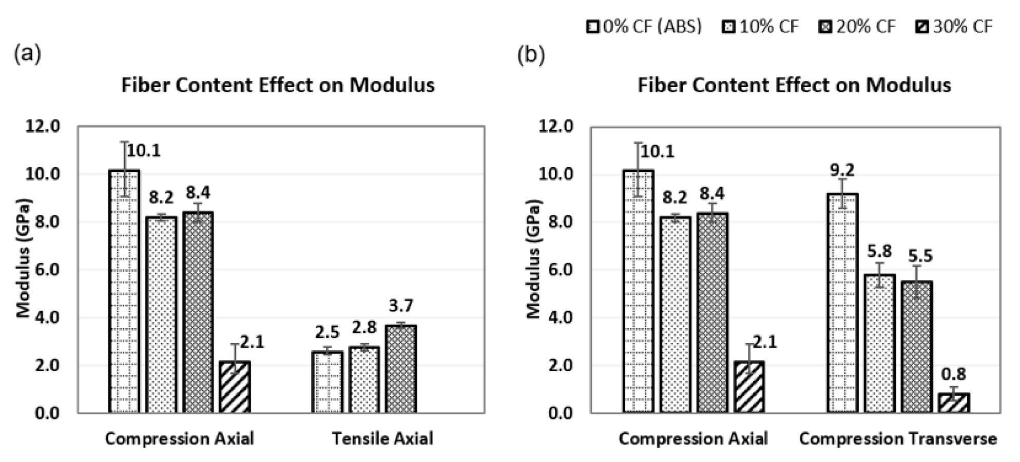
3.1.2. Compressive Modulus

The compressive modulus results which measure the stiffness of the material under compression is presented in Figure 5. Figure 5a shows the comparison of the modulus across the axial and transverse axes of the composites, while Figure 4b shows the comparison of the axial compressive and axial tensile properties.
In comparing the compressive to the tensile modulus as seen in Figure 5a, the AM composite exhibited a generally higher modulus in compression than in tension. This is similar to the material strength where the difference in the compressive and tensile values was related to the plasticity of the material under compression as against elastic characteristics exhibited in tension. The modulus was also observed to reduce with increasing fiber content, but unlike the tensile modulus which exhibits improving properties.
Across the axial axes, an 18% modulus reduction was observed at 10–20% fiber content and a reduction up to 79% for the 30% fiber content. Larger modulus reduction was observed in the transverse direction at 38% reduction for the 10–20% fiber content and up to 91% reduction for the 30% fiber content. The modulus reduction with increasing fiber content can also be related to the larger amounts of fiber-matrix interface regions which are characterized by lower properties and are the cause of the reducing modulus in line with the theory of the compressive loading failure of short-fiber thermoplastic matrix composites [34,35,36]. The higher modulus in the axial axes as seen in Figure 5b can be related to the higher bond strength through the longitudinal length of the print bead which characterizes the axial axis compared to the weaker interlayer bond strength across the print layers of the transverse axis in a similar trend as obtained for the compressive strength.

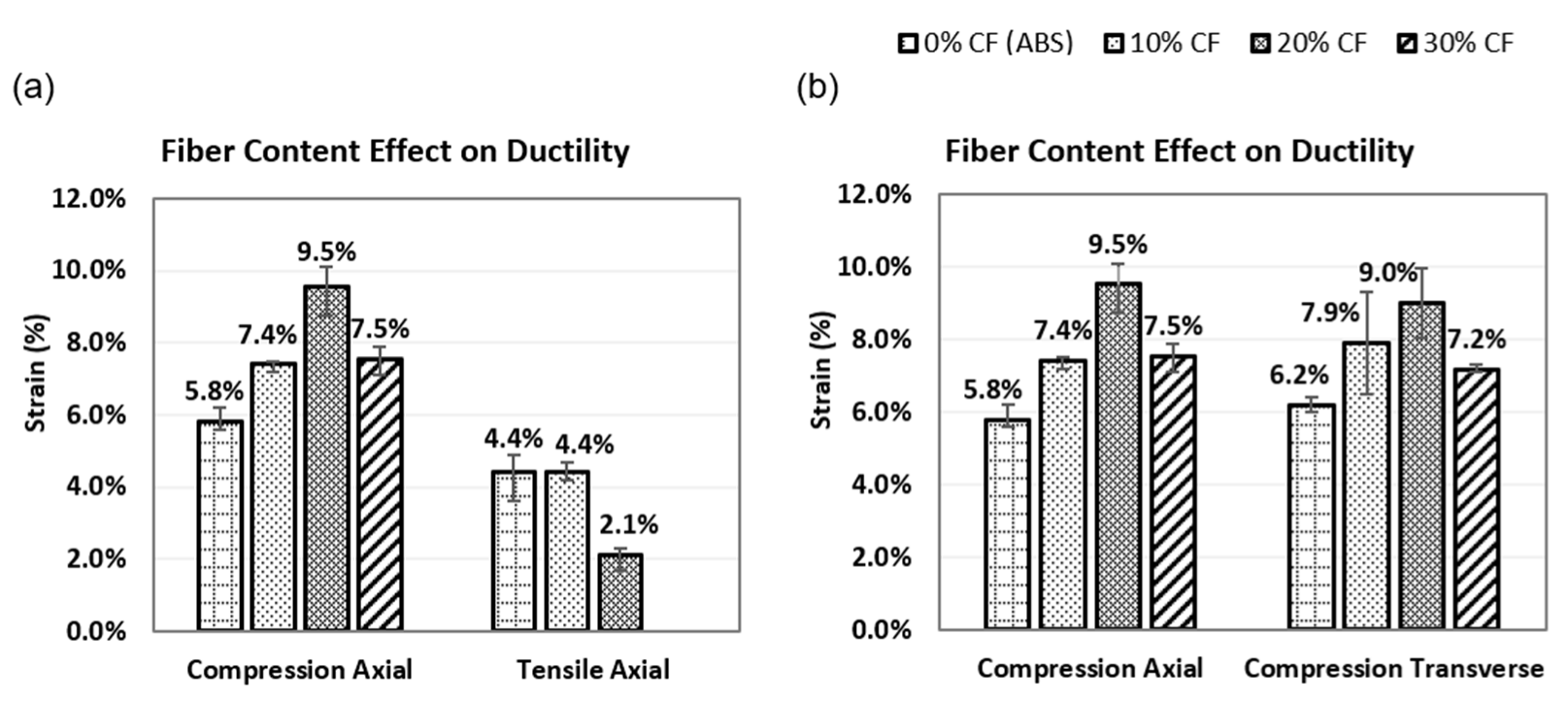
3.1.3. Compressive Ductility

The described ductility result shown in Figure 6 measures the ability of the AM composite to deform plastically before fracture. The lower strain to fracture indicates brittleness while higher strains indicate ductile characteristics.
In comparing the compressive to the tensile ductility as seen in Figure 6a, the composite exhibited in compression more than the 5% strain which is used to set the benchmark for brittle to ductile characteristics, while the tensile exhibited below the 5% benchmark value. Thus, the material features a ductile characteristic in compression and brittle characteristics in tension. The material is seen to exhibit increasing compressive ductility with increasing fiber content, with values peaking at 20% fiber content, against the tensile ductility which exhibited reduced values with increasing carbon fiber content. As discussed by Junaid et al. [37] in their ductile to brittle transitions theory of CFRP composites, a balance of ductility, strength, and modulus properties are important characteristics for the effective application of the material.
In comparing the ductility across the axial and transverse axes as seen in Figure 6b, the axial compression showed a 28% increase in ductility at 10% carbon fiber content, a 64% increase for the 20% carbon fiber content, and a 29% increase for the 30% carbon fiber content. A similar ductility trend was observed in the transverse compression but at a lower rate of increase, at 27%, for the 10% fiber content, 45% for the 20% fiber content, and a 10% increase for the 30% fiber content. The compressive ductility increase with fiber content can be related to the ability of the increased fiber content to support more plastic deformation before buckling and eventual shear failure. The ductile thermoplastic matrix dominates to support the compressive strain to failure, while the fiber fills any porosities upon compression before buckling failure.

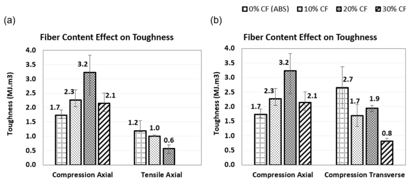
3.1.4. Compressive Toughness

The toughness property which measures the ability of the material to absorb energy and plastically deforms without fracturing is presented in Figure 7. Though determined from the area under the stress-strain curve, it is generally provided by a balance of the strength and ductility properties.
The large plastic deformation behaviors exhibited under compression relate to their energy absorption performance, which influences their toughness. Figure 7a shows the material exhibiting higher toughness in compression than in tension in line with the plastic deformation exhibited under compression compared to the elastic deformation under tension.
The compressive toughness increased up to 20% fiber content after which it stabilized. However, the tensile reduction with increasing fiber content is in line with the ductile to brittle transition theory which relates to the elastic deformation failure in tension. This is in line with the investigations by Ning et al. [13], where increasing fiber content was found to reduce the toughness, ductility, yield strength in the tensile mode. The more brittle fiber reinforcement is more active in tensile loading while the ductile thermoplastic matrix with its toughness features dominates the compressive loading. The mix of the increasing strength from the increased fiber content and ductility from the dominating thermoplastic matrix offers the material the increasing energy absorption before micro-buckling, thus, increasing toughness under compression.
When comparing compressive toughness across the axes of the composite as seen in Figure 7b, the axial compression showed a 35% increase in toughness at 10% carbon content, a 47% increase for the 20% carbon fiber content, and a 24% increase for the 30% carbon fiber content. However, a different trend was observed in the transverse axis, where toughness was found to reduce with increasing fiber content. An approximate 37% reduction was observed for the 10% fiber content, a 30% reduction for the 20% fiber content, while a reduction up to 70% was observed for the 30% fiber content.
The toughness increase in the axial axis can be related to the higher ductility across the longitudinal print layers with increasing fiber contents which are better able to withstand micro-buckling. This is different in the transverse axis where increasing fiber (reducing thermoplastic matrix) contents results in lesser bond strength of the interlayers. Hence, the result of reducing toughness with increasing fiber content is experienced across the axis. The toughness reduction trend can also be related to the more significant strength reduction across the axes which is a result of the weaker interlayer bonding across adjacent print layers that characterizes the transverse axis.

3.2. Evaluation of Failure Modes

The compressive failure mode observed during testing started as small wavelength buckling of the print layers with the eventual barreling of the samples, which can be related to reported investigations in the compressive failure of thermoplastic composites [38] Adjacent fiber-matrix and matrix-matrix interfaces buckled in similar manners such that the deformation of adjacent layers within the composite was primarily of shear deformation. The failure mode in tension was different from that observed in compression due to the difference in the effective fiber and matrix functions under the two different loading modes. While compression deformed the materials plastically by barreling before eventual shear deformation, tension deformed the materials elastically, which is due to the more active brittle carbon fiber function under tension. Figure 8 evaluates the fracture surfaces of the samples at final failure to compare material features and evaluate failure modes under compression and tension.
Figure 8a shows the internal failure images typical for AM fabricated ABS and CF-ABS under compression. The compressive loading is seen to close the intra-layers and inter-layers porosities generally exhibited within the print beads and adjacent layers of the print. The CF-ABS was observed to show coarser shearing due to the effective carbon fiber after the porosity closure which was resisting plastic deformation, hence, generating the higher ductility and toughness observed. In Figure 8b the surface failure mode of the CF-ABS composite loaded in tension showed fiber pull-out and matrix cracking dominating the failure mode, with the carbon fiber pull-out of the matrix indicating the additional impediment the breaking forces must overcome in CFRP composites before yielding. Hence, the increasing carbon fiber content can be related to increasing the reinforcing impediment, thus, increasing tensile strength and modulus as observed in testing.

4. Conclusions

In this study, the effects of fiber content on the compressive properties of AM fabricated CFRP composites using CF-ABS samples were investigated. Compressive properties were compared along the axial and transverse axis of the composite, and the axial compression was also compared to axial tensile properties. The results were reinforced with the fracture surface failure modes and the following conclusions were drawn:
  • The increasing carbon fiber content in AM fabricated short-fiber thermoplastic CFRP composites slightly reduces compressive strength and modulus. However, they increase ductility and toughness.
  • The 20% carbon fiber content provided an optimized fiber volume for AM fabricated short-fiber thermoplastic CFRP composite applications subjected to compressive loading.
  • AM fabricated CFRP composites generally demonstrate a higher compressive than tensile properties because the higher plastic deformation characterizes compressive loading and more easily redistributes stress at existing flaws.
  • The failure mode in compression starts with the fiber-matrix debonding, followed by a unidirectional buckling of the interlayers and then barreling of the composite before an eventual shear deformation of the composite.
  • The material properties trends and failure mode in compression differ from tension due to the differences in the active functions of the fiber and matrix under the different loading conditions.

Author Contributions

Conceptualization, O.A. and W.C.; methodology, O.A., W.C. and E.B.; validation, O.A., W.C. and V.A.; formal analysis, O.A., W.C. and V.A.; investigation, O.A., E.B. and V.A.; resources, O.A. and W.C.; data curation, O.A., W.C. and E.B.; writing—original draft preparation, O.A.; writing—review and editing, O.A., W.C. and E.B.; supervision, W.C. All authors have read and agreed to the published version of the manuscript.

Funding

This research received no external funding.

Data Availability Statement

The data presented in this study are available on request from the corresponding author.

Conflicts of Interest

The authors declare no conflict of interest.

References

  1. Bin Hamzah, H.H.; Keattch, O.; Covill, D.; Patel, B.A. The Effects of Printing Orientation on the Electrochemical Behaviour of 3D Printed Acrylonitrile Butadiene Styrene (ABS)/Carbon Black Electrodes. Sci. Rep. 2018, 8, 9135. [Google Scholar] [CrossRef] [Green Version]
  2. Tymrak, B.M.; Kreiger, M.; Pearce, J.M. Mechanical Properties of Components Fabricated with Open-Source 3-D Printers under Realistic Environmental Conditions. Mater. Des. 2014, 58, 242–246. [Google Scholar] [CrossRef] [Green Version]
  3. Dimas, L.S.; Bratzel, G.H.; Eylon, I.; Buehler, M.J. Tough Composites Inspired by Mineralized Natural Materials: Computation, 3D Printing, and Testing. Adv. Funct. Mater. 2013, 23, 4629–4638. [Google Scholar] [CrossRef]
  4. Martin, J.J.; Fiore, B.E.; Erb, R.M. Designing Bioinspired Composite Reinforcement Architectures via 3D Magnetic Printing. Nat. Commun. 2015, 6, 8641. [Google Scholar] [CrossRef] [Green Version]
  5. Unterweger, C.; Brüggemann, O.; Fürst, C. Synthetic Fibers, and Thermoplastic Short-Fiber-Reinforced Polymers: Properties and Characterization. Polym. Compos. 2014, 35, 227–236. [Google Scholar] [CrossRef]
  6. Goh, G.D.; Dikshit, V.; Nagalingam, A.P.; Goh, G.L.; Agarwala, S.; Sing, S.L.; Wei, J.; Yeong, W.Y. Characterization of Mechanical Properties and Fracture Mode of Additively Manufactured Carbon Fiber and Glass Fiber Reinforced Thermoplastics. Mater. Des. 2018, 137, 79–89. [Google Scholar] [CrossRef]
  7. Zhang, W.; Cotton, C.; Sun, J.; Heider, D.; Gu, B.; Sun, B.; Chou, T.W. Interfacial Bonding Strength of Short Carbon Fiber/Acrylonitrile-Butadiene-Styrene Composites Fabricated by Fused Deposition Modeling. Compos. Part B Eng. 2018, 137, 51–59. [Google Scholar] [CrossRef]
  8. Ning, F.; Cong, W.; Hu, Z.; Huang, K. Additive Manufacturing of Thermoplastic Matrix Composites Using Fused Deposition Modeling: A Comparison of Two Reinforcements. J. Compos. Mater. 2017, 51, 3733–3742. [Google Scholar] [CrossRef]
  9. Mohammadizadeh, M.; Fidan, I. Thermal Analysis of 3D Printed Continuous Fiber Reinforced Thermoplastic Polymers for Automotive Applications. In Proceedings of the 30th Annual International Solid Freeform Fabrication Symposium—An Additive Manufacturing Conference, SFF 2019, Austin, TX, USA, 12–14 August 2019; pp. 899–906. [Google Scholar]
  10. Mohamed, O.A.; Masood, S.H.; Bhowmik, J.L. Optimization of Fused Deposition Modeling Process Parameters: A Review of Current Research and Future Prospects. Adv. Manuf. 2015, 3, 42–53. [Google Scholar] [CrossRef]
  11. van de Werken, N.; Tekinalp, H.; Khanbolouki, P.; Ozcan, S.; Williams, A.; Tehrani, M. Additively Manufactured Carbon Fiber-Reinforced Composites: State of the Art and Perspective. Addit. Manuf. 2020, 31, 100962. [Google Scholar] [CrossRef]
  12. Tekinalp, H.L.; Kunc, V.; Velez-Garcia, G.M.; Duty, C.E.; Love, L.J.; Naskar, A.K.; Blue, C.A.; Ozcan, S. Highly Oriented Carbon Fiber-Polymer Composites via Additive Manufacturing. Compos. Sci. Technol. 2014, 105, 144–150. [Google Scholar] [CrossRef] [Green Version]
  13. Ning, F.; Cong, W.; Qiu, J.; Wei, J.; Wang, S. Additive Manufacturing of Carbon Fiber Reinforced Thermoplastic Composites Using Fused Deposition Modeling. Compos. Part B Eng. 2015, 80, 369–378. [Google Scholar] [CrossRef]
  14. Duty, C.E.; Kunc, V.; Compton, B.; Post, B.; Erdman, D.; Smith, R.; Lind, R.; Lloyd, P.; Love, L. Structure and Mechanical Behavior of Big Area Additive Manufacturing (BAAM) Materials. Rapid Prototyp. J. 2017, 23, 181–189. [Google Scholar] [CrossRef]
  15. Post, B.K. Additive Manufacturing in Wind Turbine Components and Tooling Project ID #: T13. 2016. Available online: https://www.energy.gov/sites/prod/files/2019/05/f62/ORNL-T13-Post%204_2_19.pdf (accessed on 8 November 2021).
  16. Post, B.K.; Richardson, B.; Lind, R.; Love, L.J.; Lloyd, P.; Kunc, V.; Rhyne, B.J.; Roschli, A.; Hannan, J.; Nolet, S.; et al. Big Area Additive Manufacturing Application in Wind Turbine Molds. In Proceedings of the 28th Annual International Solid Freeform Fabrication Symposium—An Additive Manufacturing Conference, SFF 2017, Austin, TX, USA, 7–9 August 2017; pp. 2430–2446. [Google Scholar]
  17. Kunc, V.; Hassen, A.A.; Lindahl, J.; Kim, S.; Post, B. Large Scale Additively Manufactured Tooling for Composites. In Proceedings of the 15th Japan International Sampe Symposium and Exhibition, Tokyo, Japan, 27–29 November 2017; pp. 1–6. [Google Scholar]
  18. Brenken, B.; Barocio, E.; Favaloro, A.; Kunc, V.; Pipes, R.B. Fused Filament Fabrication of Fiber-Reinforced Polymers: A Review. Addit. Manuf. 2018, 21, 1–16. [Google Scholar] [CrossRef]
  19. Meraz Trejo, E.; Jimenez, X.; Billah, K.M.M.; Seppala, J.; Wicker, R.; Espalin, D. Compressive Deformation Analysis of Large Area Pellet-Fed Material Extrusion 3D Printed Parts in Relation to in Situ Thermal Imaging. Addit. Manuf. 2020, 33, 101099. [Google Scholar] [CrossRef]
  20. Quan, Z.; Larimore, Z.; Qin, X.; Yu, J.; Mirotznik, M.; Byun, J.H.; Oh, Y.; Chou, T.W. Microstructural Characterization of Additively Manufactured Multi-Directional Preforms and Composites via X-Ray Micro-Computed Tomography. Compos. Sci. Technol. 2016, 131, 48–60. [Google Scholar] [CrossRef]
  21. Quan, Z.; Larimore, Z.; Wu, A.; Yu, J.; Qin, X.; Mirotznik, M.; Suhr, J.; Byun, J.H.; Oh, Y.; Chou, T.W. Microstructural Design and Additive Manufacturing and Characterization of 3D Orthogonal Short Carbon Fiber/Acrylonitrile-Butadiene-Styrene Preform and Composite. Compos. Sci. Technol. 2016, 126, 139–148. [Google Scholar] [CrossRef]
  22. Wang, J.; Xiang, J.; Lin, H.; Wang, K.; Yao, S.; Peng, Y.; Rao, Y. Effects of Scanning Strategy and Printing Temperature on the Compressive Behaviors of 3D Printed Polyamide-Based Composites. Polymers 2020, 12, 1783. [Google Scholar] [CrossRef] [PubMed]
  23. Lee, C.S.; Kim, S.G.; Kim, H.J.; Ahn, S.H. Measurement of Anisotropic Compressive Strength of Rapid Prototyping Parts. J. Mater. Process. Technol. 2007, 187–188, 627–630. [Google Scholar] [CrossRef]
  24. Araya-Calvo, M.; López-Gómez, I.; Chamberlain-Simon, N.; León-Salazar, J.L.; Guillén-Girón, T.; Corrales-Cordero, J.S.; Sánchez-Brenes, O. Evaluation of Compressive and Flexural Properties of Continuous Fiber Fabrication Additive Manufacturing Technology. Addit. Manuf. 2018, 22, 157–164. [Google Scholar] [CrossRef]
  25. Love, L.J.; Kunc, V.; Rios, O.; Duty, C.E.; Elliott, A.M.; Post, B.K.; Smith, R.J.; Blue, C.A. The Importance of Carbon Fiber to Polymer Additive Manufacturing. J. Mater. Res. 2014, 29, 1893–1898. [Google Scholar] [CrossRef] [Green Version]
  26. Chacón, J.M.; Caminero, M.A.; Núñez, P.J.; García-Plaza, E.; García-Moreno, I.; Reverte, J.M. Additive Manufacturing of Continuous Fibre Reinforced Thermoplastic Composites Using Fused Deposition Modelling: Effect of Process Parameters on Mechanical Properties. Compos. Sci. Technol. 2019, 181, 107688. [Google Scholar] [CrossRef]
  27. Costa, A.E.; Ferreira da Silva, A.; Sousa Carneiro, O. A Study on Extruded Filament Bonding in Fused Filament Fabrication. Rapid Prototyp. J. 2019, 25, 555–565. [Google Scholar] [CrossRef]
  28. ASTM D695-15. In Annual Book of ASTM Standards; ASTM International: West Conshohocken, PA, USA, 2015; pp. 1–8. [CrossRef]
  29. ASTM D638-14. In Annual Book of ASTM Standards; ASTM International: West Conshohocken, PA, USA, 2014; pp. 1–17. [CrossRef]
  30. Duty, C.E. Material Development for Tooling Applications Using Big Area Additive Manufacturing (BAAM); Oak Ridge National Laboratory: Oak Ridge, TN, USA, 2015. [Google Scholar] [CrossRef] [Green Version]
  31. Fleck, N.; Deng, L.; Budiansky, B. Prediction of Kink Width in Compressed Fiber Composites. J. Appl. Mech. 1995, 62, 329–337. [Google Scholar] [CrossRef]
  32. Lo, K.H.; Chim, E.S.-M. Compressive Strength of Unidirectional Composites. J. Reinf. Plast. Compos. 1992, 11, 838–896. [Google Scholar] [CrossRef]
  33. Pascual-González, C.; San Martín, P.; Lizarralde, I.; Fernández, A.; León, A.; Lopes, C.S.; Fernández-Blázquez, J.P. Post-Processing Effects on Microstructure, Interlaminar and Thermal Properties of 3D Printed Continuous Carbon Fibre Composites. Compos. Part B Eng. 2021, 210, 108652. [Google Scholar] [CrossRef]
  34. Pukánszky, B. Interfaces and Interphases in Multicomponent Materials: Past, Present, Future. Eur. Polym. J. 2005, 41, 645–662. [Google Scholar] [CrossRef]
  35. Greszczuk, L.B. On Failure Modes of Unidirectional Composites Under Compressive Loading. In Fracture of Composite Materials; Springer: Singapore, 1982; pp. 231–244. ISBN 9024726999. [Google Scholar]
  36. Dharan, C.K.H.; Lin, C.L. Longitudinal Compressive Strength of Continuous Fiber Composites. J. Compos. Mater. 2007, 41, 1389–1405. [Google Scholar] [CrossRef]
  37. Junaedi, H.; Albahkali, E.; Baig, M.; Dawood, A.; Almajid, A. Ductile to Brittle Transition of Short Carbon Fiber-Reinforced Polypropylene Composites. Adv. Polym. Technol. 2020, 2020, 6714097. [Google Scholar] [CrossRef]
  38. Thompson, R. Compressive Strength of Continuous Fiber Unidirectional Composites. 2012. Available online: https://tigerprints.clemson.edu/all_dissertations/953 (accessed on 8 November 2021).
Figure 1. Custom CFRP Composite Fabrication Process (a) Melt Mix Compounding (b) Filament Extrusion (c) Sample Fabrication.
Jcs 05 00325 g001
Figure 2. Test Samples Printing Layers Orientation (a) Axial Compression (b) Transverse Compression (c) Axial Tensile.
Jcs 05 00325 g002
Figure 3. Test Setup and Workpiece Quality (a) ASTM D695 Compression (b) ASTM D638 Tensile (c) Axial and Transverse Compressive Workpieces (d) Axial Tensile Workpiece.
Jcs 05 00325 g003
Figure 4. Fiber Content Effect on the Compressive Strength of AM Fabricated CFRP Composites (a) Axial versus Transverse Compression (b) Axial Compression versus Axial Tensile.
Jcs 05 00325 g004
Figure 5. Fiber Content Effect on the Compressive Modulus of AM Fabricated CFRP Composites (a) Axial versus Transverse Compression (b) Axial Compression versus Axial Tensile.
Jcs 05 00325 g005
Figure 6. Fiber Content Effect on the Compressive Ductility of AM Fabricated CFRP Composites (a) Axial versus Transverse Compression (b) Axial Compression versus Axial Tensile.
Jcs 05 00325 g006
Figure 7. Fiber Content Effect on the Compressive Toughness of AM Fabricated CFRP Composites (a) Axial versus Transverse Compression (b) Axial Compression versus Axial Tensile.
Jcs 05 00325 g007
Figure 8. Microscopic Evaluation of Mechanical Tested ABS versus CF-ABS [1000×] (a) Tensile Loading (b) Compressive Loading.
Jcs 05 00325 g008
Table 2. Printing Processing Parameters.
ParameterValueUnit
Infill density100%
Nozzle Temperature270°C
Bed Temperature100°C
Printing Enclosure 50 ± 5°C
Layer Thickness0.25mm
Printing Speed30mm/s
Raster angle0 and 90°
Publisher’s Note: MDPI stays neutral with regard to jurisdictional claims in published maps and institutional affiliations.

