Comparison of Specimen Geometries for Measuring Through-Thickness Tensile Mechanical Properties of Fibre-Reinforced Polymer Composites
Abstract
1. Introduction
2. Through-Thickness Geometries
2.1. Indirect Geometries
2.2. Direct Geometries
3. Materials and Methods
3.1. Materials
3.2. Specimen Machining and Preparation
3.3. Mechanical Testing
3.3.1. Indirect Loading Methods
3.3.2. Direct Loading Methods
3.4. Sampling and Measurement Uncertainty
4. Finite Element Analysis
5. Results and Discussion
5.1. Experimental Testing
5.1.1. Indirect Geometries
5.1.2. Direct Geometries
5.2. Finite Element Analysis
5.2.1. Indirect Geometries
5.2.2. Direct Geometries
5.2.3. Stress Concentrations
6. Conclusions
- Cruciform and punch-out indirect geometries provide low T-T failure strengths as a result of high stress concentrations, particularly in the cruciform geometry. These methods are also unable to determine elastic properties.
- Of the indirect geometries, the flexural three-point bend method provides the most suitable approach being able to determine T‑T Young’s modulus and strain-to-failure alongside failure strength. However, volumetric effects do need to be considered through Weibull statistics to give representative material property data. In addition, the method is strictly only suitable for unidirectional materials, and higher specimen numbers would be required to characterise woven materials with coarse fabric structures.
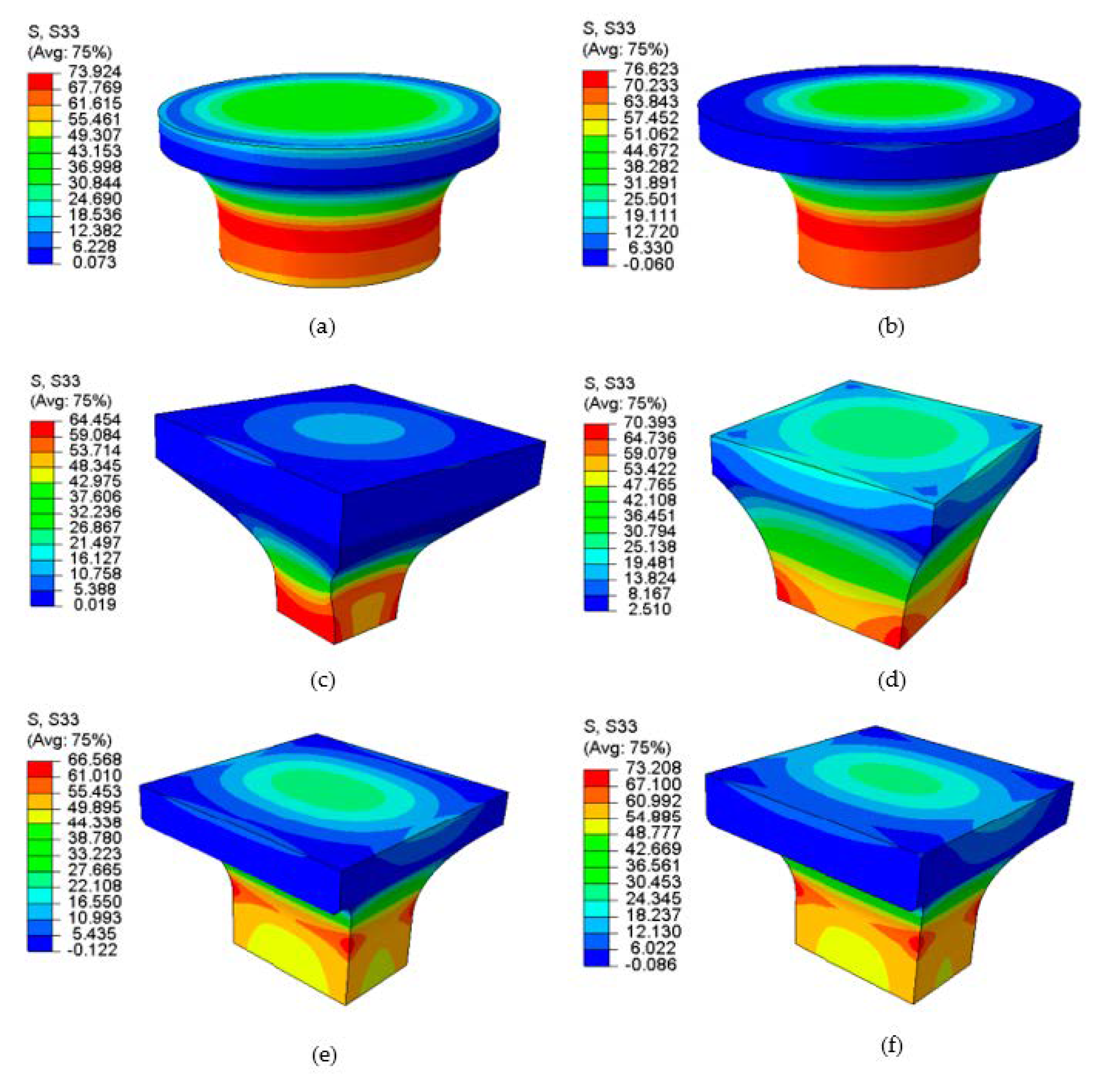
- Direct geometries showed greater consistency with regard to T-T strength and elastic properties. Discrepancies are still present, particularly for failure strength, which is attributed to stress concentration factors and volumetric effects. In all geometries excluding the bi-lateral waist, T‑T failure strength has been shown to scale linearly with stress concentration factor. Further work to increase the confidence in stress concentration values determined by FEA would provide increased knowledge for industry to use T-T properties determined from these methods.
- No direct geometry presents more difficulty with respect to testing practicality. Of all the geometries, only the RARDE Type III geometries (large and mini—which enables T-T properties to be measured on specimens extracted from thinner laminates of ≈20 mm) can determine strength properties and the full complement of elastic properties. Obtaining all properties from just one specimen reduces machining and testing costs compared to other specimen types.
- Further work building on Weibull analysis techniques could investigate the effect of volumetric and surface distributed flaws across the different geometries.
- Whilst the machining was closely inspected throughout this work to ensure minimal effects of surface-induced damage and out-of-tolerance geometries, these factors could also be variables altered to assess influence on failure strength.
Author Contributions
Funding
Acknowledgments
Conflicts of Interest
References
- Broughton, W.R. Through-thickness testing. In Mechanical Testing of Advanced Fibre Composites, 1st ed.; Hodgkinson, J.M., Ed.; Woodhead Publishing: Cambridge, UK, 2000; pp. 143–168. ISBN 1-85573-312-9. [Google Scholar]
- Gerlach, R.; Siviour, C.R.; Wiegand, J.; Petrinic, N. In-plane and through-thickness properties, failure modes, damage and delamination in 3D woven carbon fibre composites subjected to impact loading. Compos. Sci. Technol. 2012, 72, 397–411. [Google Scholar] [CrossRef]
- Shaw, R.M.; Sims, G.D. Through-Thickness Tensile Testing of Polymer Matrix Composites; Measurement Note DEPC-MN 007; National Physical Laboratory: Teddington, UK, 2004. [Google Scholar]
- ISO 20975-2:2018. Fibre-Reinforced Plastic Composites—Determination of Laminate Through-Thickness Properties. Part 2: Determination of the Elastic Modulus, the Strength and the Weibull Size Effects by Flexural Test of Unidirectional Laminate, for Carbon-Fibre Based Systems; International Organization for Standardization: Geneva, Switzerland, 2018. [Google Scholar]
- Hara, E.; Yokozeki, T.; Hatta, H.; Iwahori, Y.; Ishikawa, T. Comparison of out-of-plane tensile moduli of CFRP laminates obtained by 3-point bending and direct loading tests. Compos. Part A 2014, 67, 77–85. [Google Scholar] [CrossRef]
- ASTM D6415-06. Standard Test Method for Measuring the Curved Beam Strength of a Fiber-Reinforced Polymer-Matrix Composites; American Society for Testing and Materials: West Conshohocken, PA, USA, 2013. [Google Scholar]
- ASTM D7291-15. Standard Test Method for Through-Thickness “Flatwise” Tensile Strength and Elastic Modulus of a Fiber-Reinforced Polymer Matrix Composite Material; American Society for Testing and Materials: West Conshohocken, PA, USA, 2013. [Google Scholar]
- Hoffman, M.; Zimmermann, K.; Middenhorf, P. Determination of the Through-Thickness Strength Properties to Predict the Failure of Thick-Walled Composite Lugs. In Proceedings of the 20th International Conference on Composite Materials (ICCM 2015), Copenhagen, DK, 10–24 July 2015. [Google Scholar]
- Ferguson, R.F.; Hinton, M.J.; Hiley, M.J. Determining the Through-Thickness Properties of FRP Materials. Compos. Sci. Technol. 1998, 58, 1411–1420. [Google Scholar] [CrossRef]
- Broughton, W.R.; Gower, M.R.L.; Loderio, M.J.; Shaw, R.M. Through-Thickness Testing of Polymer Matrix Composites; Measurement Note MATC (MN) 06; National Physical Laboratory: Teddington, UK, 2001. [Google Scholar]
- Olsson, R. A survey of test methods for multiaxial and out-of-plane strength of composite laminates. Compos. Sci. Technol. 2011, 71, 773–783. [Google Scholar] [CrossRef]
- ISO/CD 20975-1. Carbon Fibre-Reinforced Plastics—Methods for Measurement of Through-Thickness Laminate Properties—Part 1: Direct Tension and Compression; International Organization for Standardization: Geneva, Switzerland, 2018. [Google Scholar]
- Kandil, F. A Procedure for the Measurement of Machine Alignment in Axial Testing; VAMAS Report No. 42; National Physical Laboratory: Teddington, UK, 2001. [Google Scholar]
- BIPM; IEC; IFCC; ILAC; ISO; IUPAC; IUPAP; OIML. Evaluation of Measurement Data—Guide to the Expression of Uncertainty in Measurement (GUM); Technical Report 100:2008; Joint Committee for Guides in Metrology: Serves, France, 2008. [Google Scholar]







| Geometry | Description |
|---|---|
| Waisted cruciform [2] | Cruciform specimen machined to form two perpendicular beams transitioned using a waisted gauge section. |
| Cylindrical punch-out [3] | Cylindrical disc specimen containing concentric rings machined through to mid-plane of specimen from both faces. |
| Flexural three-point bend [4,5] | Rectangular beam with longitudinal direction of specimen coinciding with through-thickness direction. |
| Geometry | Description |
|---|---|
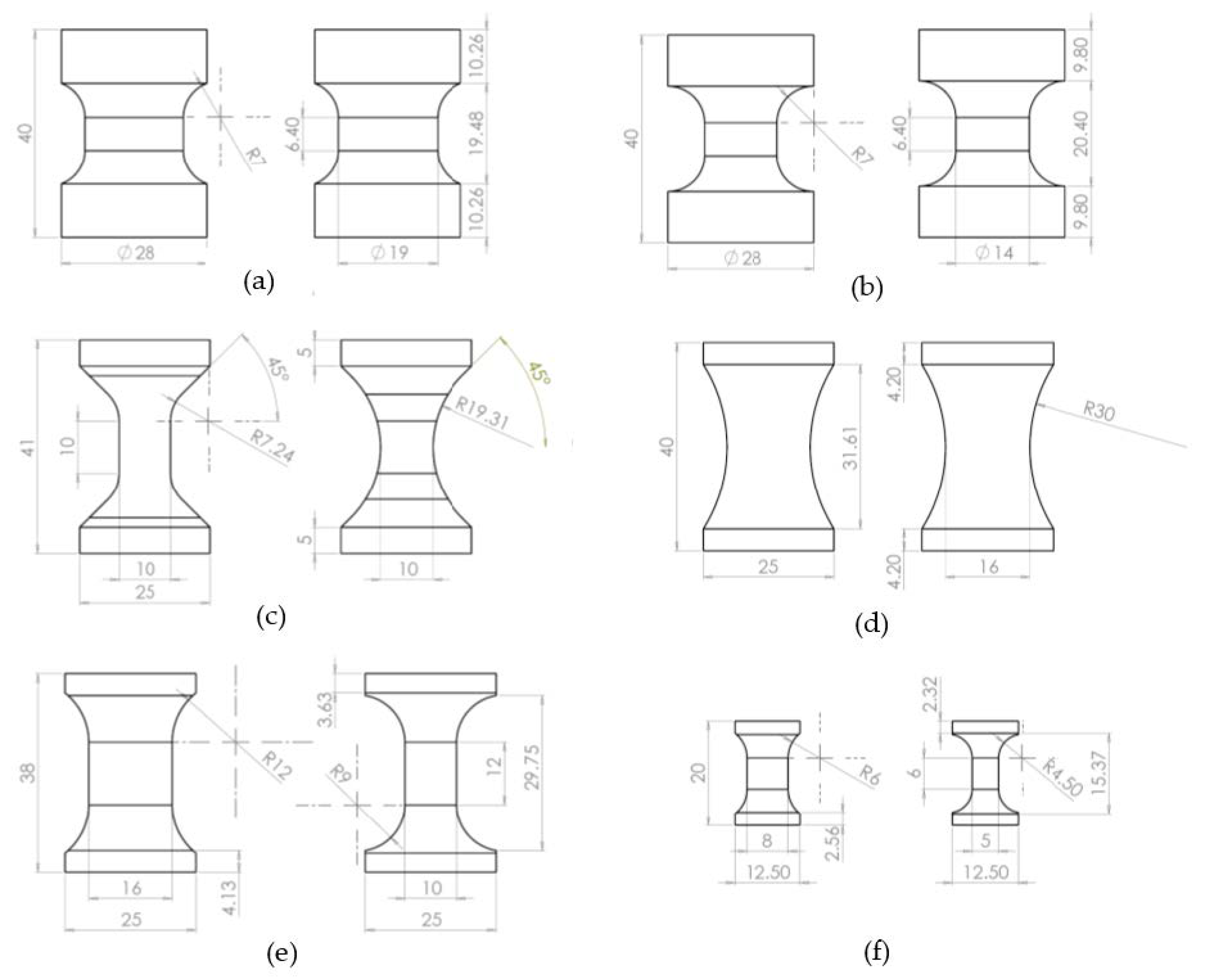
| Spool A [7] | Cylindrical cross-section waisted with a fixed cross-section along the parallel-sided gauge length of the specimen. Maximum gauge cross-section area reduction allowable in the standard |
| Spool B [7] | Cylindrical cross-section waisted with fixed cross-section along the parallel-sided gauge length of the specimen. Gauge cross-section area reduction equivalent to RARDE Type III |
| Bi-lateral waist [8] | Rectangular cross-section continuously waisted on front and back faces with straight vertical sections on lateral faces |
| RARDE Type II [9,10] | Rectangular cross-section waisted with variable cross-section along the length of specimen |
| RARDE Type III [9,10] | Rectangular cross-section waisted with fixed cross-section along the parallel-sided gauge length of the specimen |
| RARDE Type III (mini) [9,10] | RARDE Type III specimen miniaturised by reducing all specimen dimensions by factor of 1/2 |
| Geometry | Test Details | Strain Measurement | Mechanical Properties |
|---|---|---|---|
| Three-point bend | Instron Electropuls E3000 250 N load cell (class 0.5) Three-point bend rig | LVDT (± 2.5 mm travel) Type: RDPE GT2500RA | Failure strength (σ33T) Failure strain (εf33T) Young’s modulus (E33T) |
| Waisted cruciform | Instron 5500 20 kN load cell (class 0.5) U-compression rig | n/a | Failure strength (σ33T) |
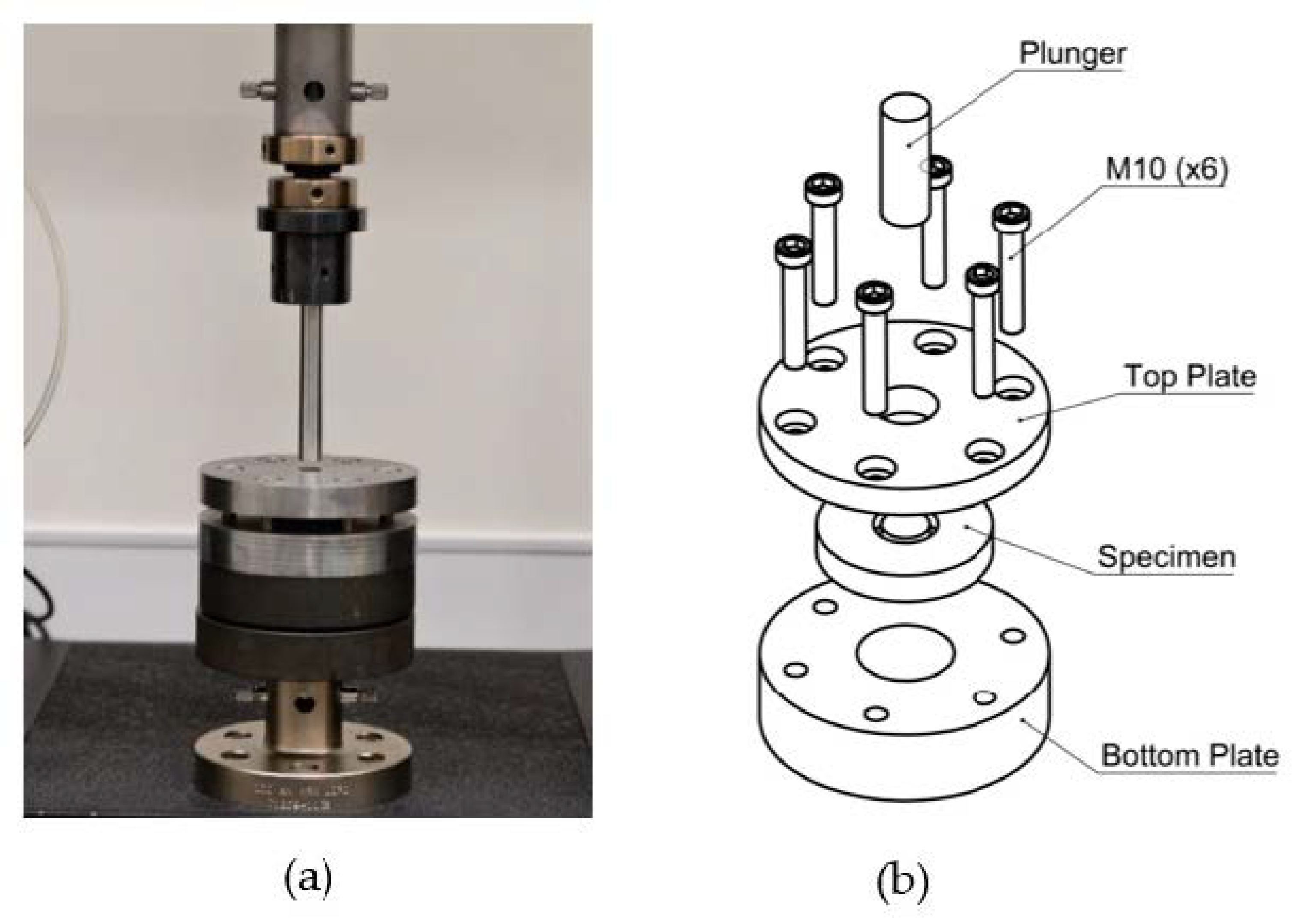
| Cylindrical punch-out | Instron 5500 100 kN load cell (class 0.5) Plate compression rig | n/a | Failure strength (σ33T) |
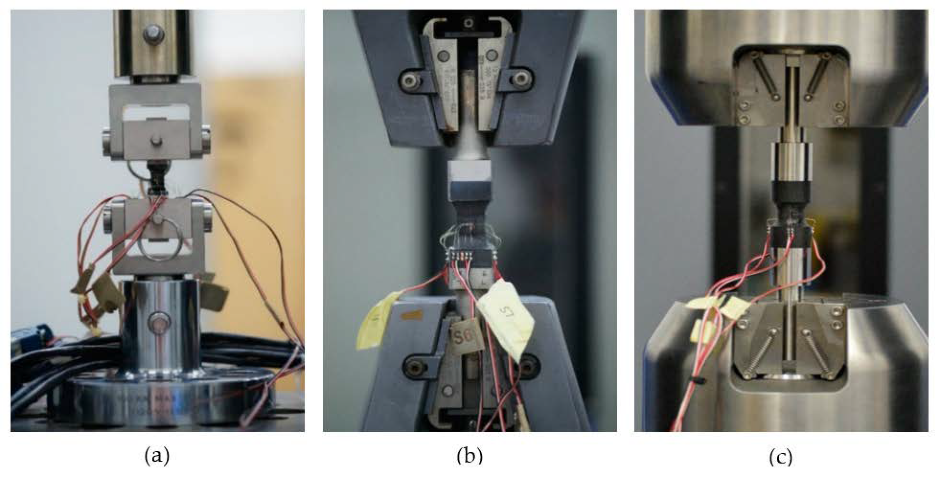
| Spool A | Instron 5985 20 kN load cell (class 0.5) Hydraulic wedge action grips | 4× uniaxial gauges (2 mm) Type: TML FLA-2-11 | Failure strength (σ33T) Failure strain (εf33T) Elastic modulus (E33T) |
| Spool B | Instron 5985 20 kN load cell (class 0.5) Hydraulic wedge action grips | 4× uniaxial gauges (2 mm) Type: TML FLA-2-11 | Failure strength (σ33T) Failure strain (εf33T) Young’s modulus (E33T) |
| Bi-lateral waist | Instron 5500 100 kN load cell (class 1) Manual wedge action grips | 2× uniaxial gauges (2 mm) Type: TML FLA-2-11 | Failure strength (σ33T) Failure strain (εf33T) Young’s modulus (E33T) |
| RARDE Type II | Instron 5500 100 kN load cell (class 1) Manual wedge action grips | n/a | Failure strength (σ33T) |
| RARDE Type III | Instron 5500 100 kN load cell (class 1) Manual wedge action grips | 4× biaxial gauges (2 mm) Type: TML FCA-2-11 | Failure strength (σ33T) Failure strain (εf33T) Young’s modulus (E33T) Poisson’s ratios (υ31, υ32) |
| RARDE Type III (mini) | Instron 5500 20 kN load cell (class 0.5) Self-aligning coupling rig | 4× biaxial gauges (1 mm) Type: TML FCA-1-11 | Failure strength (σ33T) Young’s modulus (E33T) Failure strain (εf33T) Poisson’s ratio (υ31, υ32) |
| Mechanical Property | Symbol | Value | Unit |
|---|---|---|---|
| In-plane Tensile Elastic Modulus | E11T | 67 | GPa |
| Transverse Tensile Elastic Modulus | E22T | 67 | GPa |
| Through-Thickness Tensile Elastic Modulus | E33T | 10 | GPa |
| Transverse In-plane Poisson’s Ratio | υ12 | 0.040 | - |
| Through-Thickness In-plane Poisson’s Ratio | υ13 | 0.287 | - |
| Through-thickness Transverse Poisson’s Ratio | υ23 | 0.479 | - |
| In-plane Shear Modulus | G12 | 4.45 | GPa |
| Through-Thickness Shear Modulus | G13 | 4.25 | GPa |
| Through-Thickness Shear Modulus | G23 | 4.25 | GPa |
| Test Method | E33T (GPa) | σ33T (MPa) | εf33T (%) |
|---|---|---|---|
| Three-point bend | 9.3 (±0.1) | 94 (±2) | 1.06 (±0.02) |
| Cruciform | - | 10 (±1) | - |
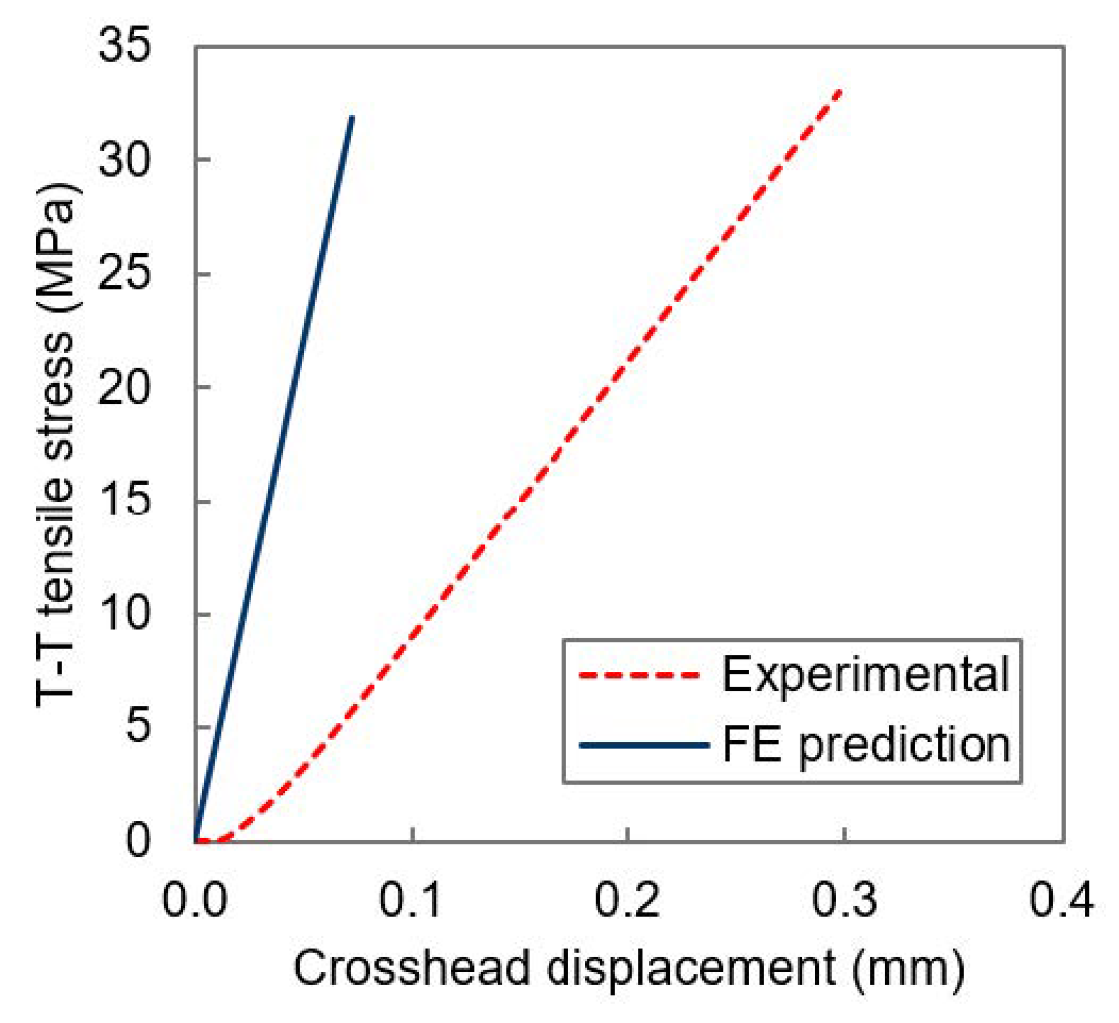
| Punch-out | - | 33 (±1) | - |
| Test Method | E33T (GPa) | υ31 | υ32 | σ33T (MPa) | εf33T (%) |
|---|---|---|---|---|---|
| Spool A | 9.2 (±0.1) | - | - | 58 (±2) | 0.67 (±0.03) |
| Spool B | 9.3 (±0.1) | - | - | 62 (±1) | 0.71 (±0.03) |
| Bi-lateral waist | 10.9 (±0.2) | - | - | 55 (±2) | 0.53 (±0.03) |
| RARDE Type II | - | - | - | 54 (±1) | - |
| RARDE Type III | 10.3 (±0.1) | 0.08 (±0.02) | 0.08 (± 0.01) | 48 (±7) | 0.49 (±0.12) |
| RARDE Type III (mini) | 9.8 (±0.2) | 0.07 (±0.04) | 0.07 (± 0.04) | 54 (±4) | 0.58 (±0.09) |
| Test Method | E33T (GPa) | σ33T (MPa) | εf33T (%) | Peak σ33T (MPa) | scf |
|---|---|---|---|---|---|
| Three-point-bend | 9.3 | 99 | 1.08 | 99 | 1.00 |
| Cruciform | - | 10 | - | 41 | 4.02 |
| Punch-out | - | 32 | - | 34 | 1.07 |
| Test Method | E33T (GPa) | σ33T (MPa) | εf33T (%) | Peak σ33T (MPa) | scf |
|---|---|---|---|---|---|
| Spool A | 9.4 | 58 | 0.62 | 74 | 1.27 |
| Spool B | 9.6 | 62 | 0.65 | 77 | 1.24 |
| Bi-lateral waist | 10.7 | 55 | 0.52 | 64 | 1.17 |
| RARDE Type II | 9.4 | 54 | 0.58 | 70 | 1.30 |
| RARDE Type III | 10.0 | 49 | 0.49 | 67 | 1.37 |
| RARDE Type III (mini) | 10.0 | 54 | 0.54 | 73 | 1.36 |
Publisher’s Note: MDPI stays neutral with regard to jurisdictional claims in published maps and institutional affiliations. |
© 2021 by the authors. Licensee MDPI, Basel, Switzerland. This article is an open access article distributed under the terms and conditions of the Creative Commons Attribution (CC BY) license (http://creativecommons.org/licenses/by/4.0/).
Share and Cite
Pemberton, R.; Crocker, L.; Poole, M.; Shaw, R.; Gower, M. Comparison of Specimen Geometries for Measuring Through-Thickness Tensile Mechanical Properties of Fibre-Reinforced Polymer Composites. J. Compos. Sci. 2021, 5, 84. https://doi.org/10.3390/jcs5030084
Pemberton R, Crocker L, Poole M, Shaw R, Gower M. Comparison of Specimen Geometries for Measuring Through-Thickness Tensile Mechanical Properties of Fibre-Reinforced Polymer Composites. Journal of Composites Science. 2021; 5(3):84. https://doi.org/10.3390/jcs5030084
Chicago/Turabian StylePemberton, Rory, Louise Crocker, Matthew Poole, Richard Shaw, and Michael Gower. 2021. "Comparison of Specimen Geometries for Measuring Through-Thickness Tensile Mechanical Properties of Fibre-Reinforced Polymer Composites" Journal of Composites Science 5, no. 3: 84. https://doi.org/10.3390/jcs5030084
APA StylePemberton, R., Crocker, L., Poole, M., Shaw, R., & Gower, M. (2021). Comparison of Specimen Geometries for Measuring Through-Thickness Tensile Mechanical Properties of Fibre-Reinforced Polymer Composites. Journal of Composites Science, 5(3), 84. https://doi.org/10.3390/jcs5030084


