Article

Investigation of the Mechanical Properties of Vinylester-Based Sheet Moulding Compound (SMC) Subject to Particle Recycling

Institute for Plastics Processing (IKV), Faculty of Mechanical Engineering, RWTH Aachen University, 52074 Aachen, Germany
*
Author to whom correspondence should be addressed.
J. Compos. Sci. 2022, 6(3), 84; https://doi.org/10.3390/jcs6030084
Submission received: 27 January 2022 / Revised: 24 February 2022 / Accepted: 28 February 2022 / Published: 8 March 2022
(This article belongs to the Special Issue Recycled Polymer Composites: Futuristic Sustainable Material)

Abstract

:
In light of climate change, fiber-reinforced plastics (FRP) are becoming increasingly important due to their lightweight construction potential. This benefit is additionally expanded on with the low cycle times, scrap rates and material costs of Sheet Moulding Compounds (SMC), making it the most often used material on the FRP market. While extensive studies regarding the recycling of SMC with unsaturated polyester-based matrices (UP-SMC) have been conducted in the past, this is not the case for vinylester-based SMC (VE-SMC). In this research, VE-SMC components were subject to a particle-recycling approach. Recyclate in the form of VE-SMC regrind was used to substitute SMC matrices during the compounding process. The dependence of the mechanical properties and failure behavior of VE-SMC containing regrind was investigated by means of microscopic and mechanical test methods for varying mass proportions of SMC regrind. Due to the addition of SMC regrind, a decreased fiber/matrix adhesion was observed. Furthermore, an increase in pore formation was observed with an increasing proportion of SMC regrind. The flexural modulus increased by 20% with a low percentage of regrind (ωrSMC = 10 wt.%) in comparison to virgin SMC. In contrast, the tensile properties decrease (up to 30%) with the addition of SMC regrind independent of the investigated proportions of SMC regrind.

1. Introduction

Due to their lightweight construction potential and durability, fiber-reinforced plastics (FRP) are finding ever-wider applications, ranging from the transport sector to the construction and electronical sector [1]. The FRP market is extremely agile and has growing continuously by 5–10% year-over-year [2]. Compared with non-reinforced materials, FRPs enable a higher degree of weight-optimization and functional component design potential, and are therefore increasingly used to reduce fuel consumption and emissions [3,4].
The material classes of Sheet Molding Compounds (SMC) and Bulk Molding Compounds (BMC, which is similar in composition to SMCs but usually have a lower fiber volume fraction (vF)) are the largest market segment in the FRP industry, accounting for around a quarter of the volume processed. These semi-finished products can be processed in large production volumes and low cycle times using compression moulding (SMC/BMC) or injection moulding (BMC) methods. The total production volume in 2019 in Europe alone accounted for 287 kilotons [1].
However, so far, there is a lack of established closed-loop material cycles for the recovery and subsequent recycling of these materials. The increasing industrial and societal relevance of resource efficiency with regard to climate change, which has been emerging for years, increases the demand for FRP recycling strategies. Due to the inadequate separability of fiber and matrix as well as fillers and additives, FRP components can only be recycled at great expense [5].
The focus of previous research projects on the recycling of non-SMC FRP with thermoset matrix is on thermal recycling (e.g., pyrolysis) and chemical recycling (e.g., solvolysis). In both processes, the plastic matrix is decomposed or broken down by a hydrolysis reaction or alcoholysis reaction, so that only the fibers can be recovered [6,7]. These processes are very energy-intensive and, due to their low economic efficiency, are currently mainly used for recycling FRP with cost-intensive carbon fiber reinforcement [8]. Glassfiber-reinforced plastics (GFRP), which account for over 95% of the international FRP market, are therefore not recycled in these processes [1].
GFRP, such as SMC, are often recycled mechanically. The composite is broken down by mechanical processes so that particle and fiber fractions are reclaimed for the reapplication of the material [5]. In contrast to thermal and chemical recycling processes, mechanical recycling is inexpensive, less energy-intensive and does not require the use of environmentally harmful substances. However, the fiber matrix bond cannot be completely removed during mechanical recycling, so the material bond remains intact [7,9].
During mechanical recycling, SMC components are ground by means of size-reduction processes such as hammer or cutting mills. The fractions of different sizes, such as resin-rich powder and fibers of different lengths still embedded in the resin, can be separated through a sieve. The mechanical treatment shortens the fibers and reduces their mechanical properties. The regrind is used, for example, in the SMC and BMC industry as a substitute filler instead of naturally occurring calcium carbonate. In some cases, component weights can be reduced through lower densities of the recyclate [5,10,11]. The fiber-containing particles can be re-used as reinforcing material. However, the mechanical properties are hardly increased compared to ordinary reinforcing fibers because of the poor adhesion of the recycled fibers to the matrix. The weight proportion of recycled fillers in the FRP is limited as this has a great influence on further processing. Besides SMC viscosity, mechanical properties are also strongly influenced. Therefore, the weight percentage of recycled filler is an unclear variable [5,12].
There are different resin systems available for manufacturing composites. Recently, Ferdous et al. discussed mechanical properties of polyester- and vinylester-based compound in the literature. Their results show that the resin system plays a great role in fatigue-failure mode. Vinylester-based resin systems create a rigid bond with fibers resulting in GFRP laminates more prone to stress concentration under cyclic loading [13].
Furthermore, a varied amount (between 30% and 50% of the weight of resin) of ceram in the phenolic-based matrix to improve fire resistancy was investigated by Ferdous et al. The results show the addition of ceram up to 50% ceram by weight of the resin resulted in only a 15% and 25% reduction in tensile strength in the longitudinal and transverse direction, respectively. Furthermore, the addition of 50% ceram powder improved the bending modulus by 37%. However, this led to the composite laminates failing prematurely due to delamination [14].
Several investigations regarding the recycling of FRPs, especially focusing on the reuse of SMC with unsaturated polyester-based matrices (UP-SMC) regrind as substitute for filler material in new SMC structures, were carried out in the 1990 s [15,16,17,18,19,20,21,22], whereas in the following two decades, further research was promoted to a noticeably lesser extent. In Germany, the company ERCOM Composite Recycling GmbH-Kunststoffaufbereitung, Rastatt, carried out mechanical recycling of SMC at the beginning of the 1990s. Since it was not profitable in the long term, ERCOM had to close down due to insolvency [23].
The size and chemical composition of filler materials may influence fiber-matrix adhesion and matrix-failure initialization in SMC [24,25,26]. A deep understanding of the resulting mechanical properties is therefore essential in ensuring the reliable application of recycled SMC. Palmer et al. evaluated the resulting mechanical properties in particle recycling of UP-SMC, showing that the interface of the fresh matrix with the recycled matrix is not a weak point. Mechanical failure under stress is observed in the virgin matrix fraction of the SMC [27]. Adding the larger fiber-containing particles proves to be more complicated and a reduction in strength can be expected. The reason is assumed to be poor adhesion of the SMC regrind to the polymer matrix. By subsequent treatment of the particle surface, better adhesion can be achieved and the reduction of the mechanical properties can be minimized [5].
SMC regrind exhibits a higher adsorption ratio of the resin compared to the conventionally used filler calcium carbonate. Consequently, the processing viscosity increases, which may limit fiber wetting. Since the density of SMC regrind is lower than that of calcium carbonate, the component weight decreases by 5% when applying a weight percentage of SMC regrind of ωrSMC = 10 wt.% (kgreg/kgSMC 100) [5]. It has also been shown that an extended mixing process of the SMC resin with the SMC regrind has a positive effect on the mechanical properties. This is explained by a better homogenization and wetting of the recyclate with the virgin resin [12].
Vinylester resins are used for SMC components that require higher physical and mechanical properties, for example, for structural applications [28]. They are characterized by good thermomechanical properties while at the same time they exhibit high curing speeds and thus a high productivity. Their molecules are quite similar to UP molecules; however, a double bound is located in the terminal position of the chain [29,30].
Past research focused on the re-use and application of regrinds from UP-SMC. However, fiber wetting behavior and resulting failure mechanisms in vinylester-based SMC (VE-SMC) differ, thus making it necessary to investigate the effects of the use of recyclates with VE SMC. Therefore, in this work, the influence of the weight proportions of recycled VE-SMC regrind on processing behavior and mechanical properties are investigated.
Furthermore, the practical investigation of this research is different to previous investigation, as the SMC regrind is applied to replace part of the resin instead of substituting the filler material. Substituting the resin instead of using recyclates as filler material facilitates a further increase in the sustainability of the recycled components.
Within the scope of this work, the question of how much by SMC recyclate can be used to substitute resin in the production of SMC components without causing significantly negative effects on the mechanical properties is to be answered. In order to test the influence of the recyclate on mechanical properties, SMC components with increasing recyclate content between 10 and 30 weight percent (wt.%) of the resin are investigated.
For the investigations of this research, SMC components with SMC regrind weight percentages of ωrSMC = 0 wt.% (reference); 10 wt.%; 20 wt.%; 30 wt.% are characterized in order to detect the effects of an increasing proportion of recyclate. The SMC regrind as well as components with varied mass–weight percentages of SMC regrind are analyzed microscopically. Furthermore, the respective SMC components are comparatively analyzed in regard to the tensile and bending properties.

2. Materials and Methods

2.1. Materials

The terms depicted in Table 1 are defined to ensure a distinct material identification within this work.
For the practical investigations of this work, SMC components were manually manufactured by hand lay up on a laboratory scale. In order to ensure the comparability of manually manufactured SMC materials of this research, the formulation of the SMC resin was adopted from a glassfiber-reinforced VE-SMC with a fiber weight proportion of 50 wt.% by BYK Chemie GmbH, Wesel (Germany). The SMC components that were shredded and re-used as SMC regrind were also manufactured form the same BYK material. The components of the SMC resin in parts per hundred resin are shown in Table 2.
The SMC resin consists of several components. The basic resin of the matrix is the vinylester resin which is characterized by improved mechanical properties and chemical resistance. For shrinkage compensation, a low profile additive was used. This solution of saturated polyester (PES) in styrene, which is easily thickened by magnesium oxide, can provide a high filler charge and good surface quality. For additional dispersion enhancement and shrinkage compensation, a thermoplastic polyethylene (PE) powder was used. Peroxides that decompose at temperatures between 100–130 °C and serve as polymerization initiators were used as curing agents. In addition, a magnesium oxide (MgO) paste was used to thicken the resin. Furthermore, two process additives from the manufacturer BYK Chemie GmbH, Wesel (Germany) were used. The processing additive BYK-P 9085 improves the flow behavior and stabilizes the compound. It also has good release properties in the mold. Furthermore, the wetting and dispersing additive BYK 9076 was used for improved fiber wetting. This additive also prevents phase separation of thermosetting resin and the thermoplastic additive. The SMC resin has a high reactivity for rapid thickening and accumulates to a density of 1.6 g/cm3.
A glass fiber (GF) roving was used as reinforcing fiber. The glass fibers are E-glass with a titer of 2400 tex. A thermoplastic hot-melt adhesive yarn with a titer of 167 dtex was used to consolidate and fix the cut glass fibers. A styrene-proof polyamide (PA) film was used as the carrier film. The film is characterized by good tear resistance and prevents the evaporation of styrene during storage.
To improve the comparability of SMC characteristics of the SMC preform manufactured by BYK, a fiber weight proportion of 50 wt.% was desired for the manufacturing of the SMC preforms. However, preliminary tests have shown that sufficient distribution of the viscous resin on the glass fiber preform is not possible using the process described in Section 2.2, leading to poor impregnation of the fibers in particular along the preform edges, as shown in Figure 1. In order to ensure sufficient fiber impregnation, the fiber weight proportion of the SMC preforms for the comparative investigation was therefore reduced to 35 wt.%. The resulting properties of the SMC material used in this study are listed in Table 3.

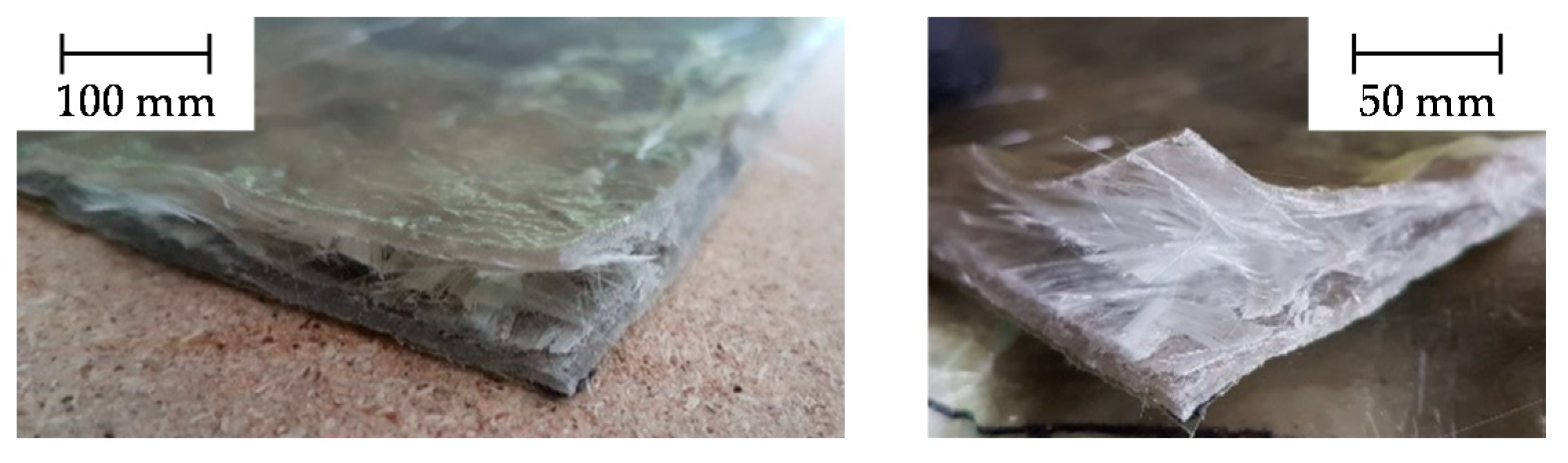
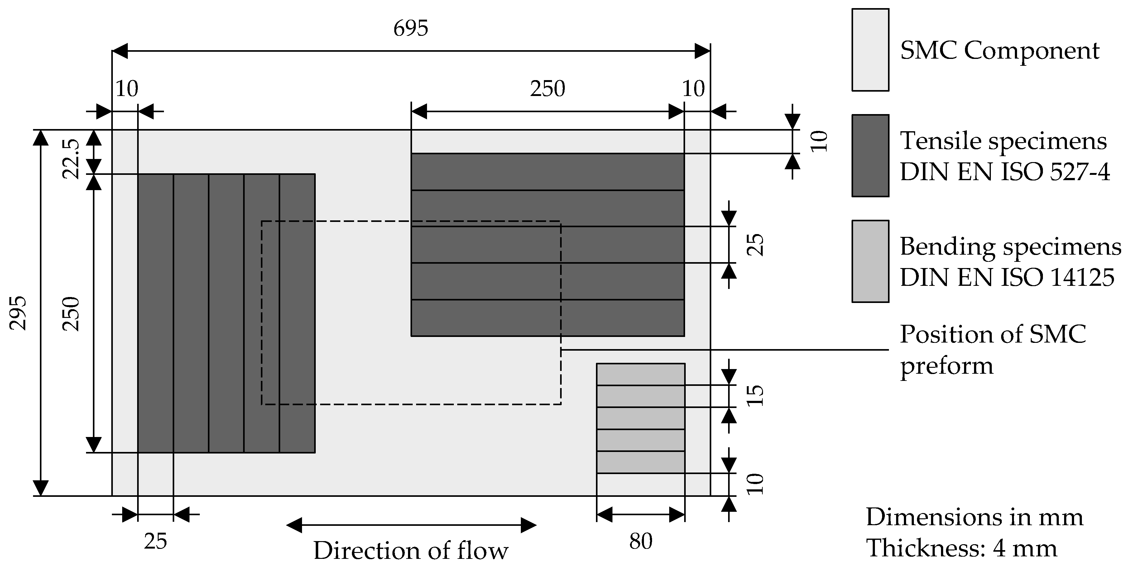
2.2. Manufacturing of SMC Components on a Laboratory Scale

The manufacturing of the SMC components for the experimental investigations of this research can be subdivided into the six steps, as shown in Figure 2.
First, in order to generate SMC regrind from compression moulded SMC components, the VE-SMC components were pre-crushed by means of a cutting mill from the manufacturer Rapid Granulator AB, Bredaryd (Sweden). The cutting unit mechanically crushes the SMC components. Since the crushed fractions have a particle size distribution, a perforated disc integrated in the mill was used to ensure a defined particle size. The pre-crushed material was further processed using a commercial mixer from the manufacturer Blendtec, Utah (USA), to facilitate further fragmentation. Finally, the ground material was sieved by a fine screen with a mesh width of 0.7 mm. The particle size of the powder is therefore a maximum of 0.7 mm and is suitable for further processing as a substitution of resin in the manufacturing of the SMC preforms.
Second, the SMC resin was prepared with a varied proportion (ωrSMC = 0 wt.%; 10 wt.%; 20 wt.%; 30 wt.%) of SMC regrind. The SMC regrind substitutes the VE resin proportionally, since a certain mixing ratio must be maintained and all the required proportions of the individual components are adjusted accordingly. Two different types of stirrers with a diameter of 60 mm were used to achieve an optimal homogenization of the resin paste. First, a three-bladed paddle stirrer was used to homogenize all liquid components. Second, a toothed dispersing disk was used in order to generate high shear forces. Thus, all solid components, such as the SMC regrind, can be homogeneously incorporated and dispersed into the paste without the occurrence of agglomerates [31]. The added recyclate caused the viscosity of the SMC resin to increase significantly by almost 40% (measured by plate plate rheometer following DIN EN ISO 3219). To ensure good manual distribution of the resin paste on the carrier film, a new SMC resin mixture was individually prepared for each preform. Before the SMC resin was further processed, the mixture was vented in a vacuum oven for 30 min.
Third, the reinforcing fibers were prepared by a fiber spraying process. By means of this process, a semi-finished GF preform with random fiber orientation was manufactured [32,33]. Thus, the preforms manufactured with fiber spraying correspond very well to the reinforcing fibers in industrial SMC production. The GF roving as well as a thermoplastic binder yarn were fed to an integrated cutting unit, which cuts the fibers to a defined length of 50 mm. A suction unit ensures a short-term fixation of the cut and loose fibers. A hot-air unit installed at the robot head melts the thermoplastic binder yearn and ensures the stability of the preform by bonding the binder with the GF. After a short cooling phase, the GF preform can easily be handled.
Fourth, the SMC preform was manually laid up. This process can be subdivided into four steps, depicted in Figure 3. The PA carrier foil was coated with the necessary amount of SMC resin (1). Then, the coated carrier foil was turned down and the bottom side of the glass fibers were impregnated with the resin (2) by means of venting rollers. The venting rollers also ensure that the preform is vented in order to minimize the formation of pores in the pressed SMC compounds. Subsequently, the impregnation was repeated for the top side of the preform (3 and 4). The impregnation from both sides was used to achieve a more uniform impregnation of the glass fibers.
Fifth, the SMC preforms were stored for 17 h at 30 °C and subsequently for 72 h at room temperature for maturing. The material was matured to increase the viscosity to 20,000–150,000 Pa·s, which is the required viscosity for ensuring sufficient fiber flow during processing [34]. For this purpose, the SMC preforms were shrink-wrapped in styrene-proof foil and initially stored at 30 °C for 17 h and subsequently stored at room temperature for a further 72 h in an autoclave at ambient pressure.
Sixth, the SMC components were compression moulded on an 1800 t hydraulic composite press by Schuler AG, Göppingen (Germany) at Aachen Center for Integrative Lightweight Production (AZL), Aachen. The compression parameters are listed in Table 4. Before each pressing process, a release agent (Frekote 770 NC, Loctite, Düsseldorf (Germany)) was applied to the tool in order to allow easy demoulding of the SMC components. After the carrier foil was removed from the SMC preform, the preform was placed centrally on the pre-tempered tool to ensure an even flow. The outer dimensions of the SMC components are 695 × 295 × 4 mm3 and the edges of the component geometry prevented misalignment of the fibers alongside the edges. After demoulding, the SMC components are cooled for 24 h at room temperature. The SMC components for varied SMC regrind content are depicted in Figure 4. For each SMC regrind content investigated in this work, two SMC components were manufactured and experimentally investigated.

2.3. Experimental Methods

Figure 5 shows an overview of the experimental design further explained in the following.

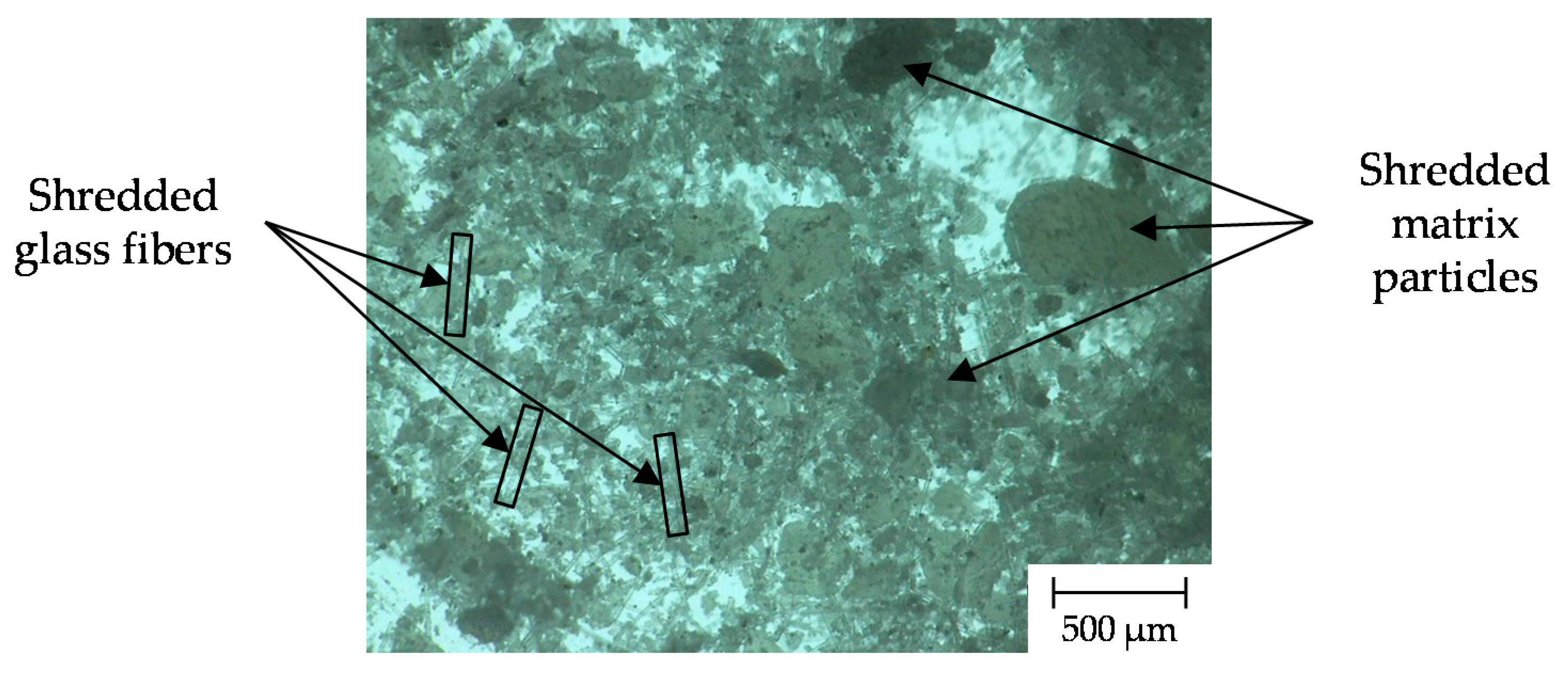
2.3.1. Microscopic Investigations

Two digital light microscopes, VHX-600 and VHX-5000 from KEYENCE Deutschland GmbH, Neu-Isenburg (Germany), were used for analysis of the SMC regrind as well as the SMC components. The SMC regrind was examined microscopically for a better assessment of structure and topography. The particle geometry allows conclusions to be drawn about impregnation quality and integration into the compound [31].
In order to analyze the material distribution of the composite, the microstructure of the SMC components was investigated by means of the VHX-5000 [35]. Three samples were randomly selected from each SMC component and embedded in a cold-curing epoxy resin. The removal positions of the samples were distributed over the whole component. After 24 h of curing, the specimens were sanded and polished with the sanding and polishing machines RoroPol21 by Struers GmbH, Willich (Germany), and Saphir 560 by ATM Qness GmbH, Mammelzen (Germany). The remaining impurities were removed in an ultrasonic bath.
The microsection of the SMC components allowed for a qualitative assessment of fiber/matrix adhesion [36]. Thus, for further investigation of the fiber/matrix impregnation, a scanning electron microscopic (SEM) was used to observe the fracture surfaces of the SMC components. Typically, images captured with a scanning electron microscope have a high depth of focus and thus allow the analysis the corresponding fiber/matrix adhesion, which has a decisive influence on the mechanical properties of SMC [36]. Therefore, three small rods were taken from each SMC components and notched after preparation. The specimens were then deep-frozen in liquid nitrogen and broken apart (cryogenic breakage). Prior to evaluation, the surface was made electrically conductive by the physical vapor deposition (sputtering) of a gold layer. The acceleration voltage used for the recordings w 2 kV.

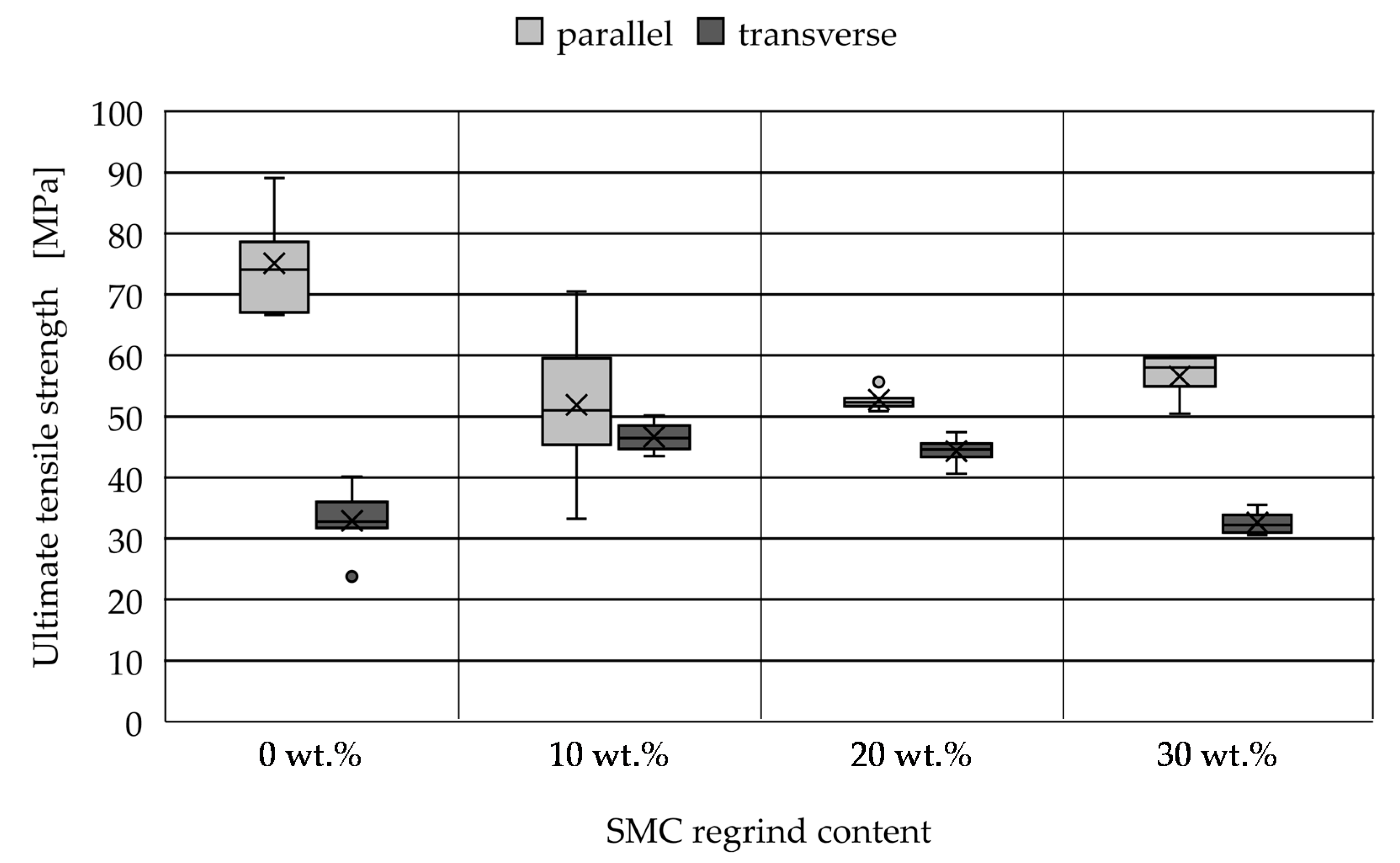
2.3.2. Mechanical Testing

To characterize the mechanical properties of SMC components, tensile tests (DIN EN ISO 527-4) and four-point bending tests (DIN EN ISO 14125) were conducted. As SMC components exhibit flow-induced anisotropic areas alongside the edges due to the pressing process, an area of 10 mm was cut off on all sides [37]. For each investigated regrind content, three test plates were manufactured for the mechanical tests. Ten tensile specimens were extracted from each test plate. Due to the possibly anisotropic areas, five specimens were withdrawn in parallel and five specimens transverse to the direction of flow. Furthermore, five bending specimens were selected parallel to the direction of flow. All test specimens were removed by a water-cooled diamond circular saw according to the sawing plan depicted in Figure 6. The specimens were manufactured in accordance with DIN EN 13421, however, the mold coverage of 50% deviates from the 25–30% specified in the standard. The higher mold coverage was chosen in order to achieve a more homogeneous heating of the SMC preform after inserting into the heated mold.

Tensile Tests

The tensile tests were performed on a universal testing machine type Z150 from Zwick/Roell AG, Ulm (Germany), with a 150 kN load cell. Following DIN EN ISO 527-4, the test settings are listed in Table 5. The elastic modulus was determined in the strain range from 0.05–0.25%. Contact extensometers were used to measure the strain during the test procedure. The tensile test specimens have the dimensions 250 × 25 × 4 mm3 and correspond to test specimen type 2 according to DIN EN ISO 527-4.

Four-Point Bending Tests

Four-point bending tests following DIN EN ISO 14125 were performed to determine bending stress and bending modulus. Compared to the three-point-bending test, a constant bending moment between the compression fins allows a larger and more homogeneous test range [38]. The testing machine used is a universal testing machine type Z100 from Zwick/Roell AG, Ulm (Germany), with a 100 kN load cell, the test settings are listed in Table 6. The bending modulus was determined in the strain range of 0.05–0.25%. The bending test specimens with the dimensions 80 × 15 × 4 mm3 correspond to test specimen type class II according to DIN EN ISO 14125.

3. Results and Discussion

3.1. Validation of SMC Manufacturing on a Laboratory Scale

Prior to analyzing the influence of SMC regrind content, the manual manufacturing of the SMC was verified. Thus, the mechanical properties of the SMC components with ωrSMC = 0 wt.% recyclate content manually manufactured for this research are compared with the conventional SMC manufactured by BYK. The formulation of the BYK material is identical to the ωrSMC = 0 wt.% formulation used in this work, with the difference that the BYK material fiber weight proportion is 50 wt.% instead of 35 wt.%. The mechanical properties are compared in Table 7. Since all SMC preforms were produced under the same conditions and the properties were examined as a function of the proportion of recycled material, the findings of this work permit a valid comparative evaluation.

3.2. Microscopic Characteristics of the SMC Regrind

In Figure 7, a structural overview of the SMC regrind at 100× magnification is depicted. It is noticeable that there is a large particle-size distribution. Subsequently, the regrind was divided into a fine and coarse fraction by sieving using a mesh width of 0.7 mm.
For closer examination, the fine fraction was viewed at 400× magnification and the coarse fraction at 300× magnification, which is depicted in Figure 8. The microscopic image of the fine fraction (left) shows that small matrix particles adhere to the fiber fragments. Furthermore, the fiber fragments differ significantly in length. Small loose matrix particles are also visible. The microscopic image of the coarse fraction (right) presents an example of a matrix-containing particle in which fibers are embedded. The assumption that the maximum particle size by using the fine sieve is 0.7 mm was confirmed by microscopic examination. The fine fraction therefore mainly consists of fibrous particles and small matrix particles, while the coarse fraction is dominated by matrix particles.

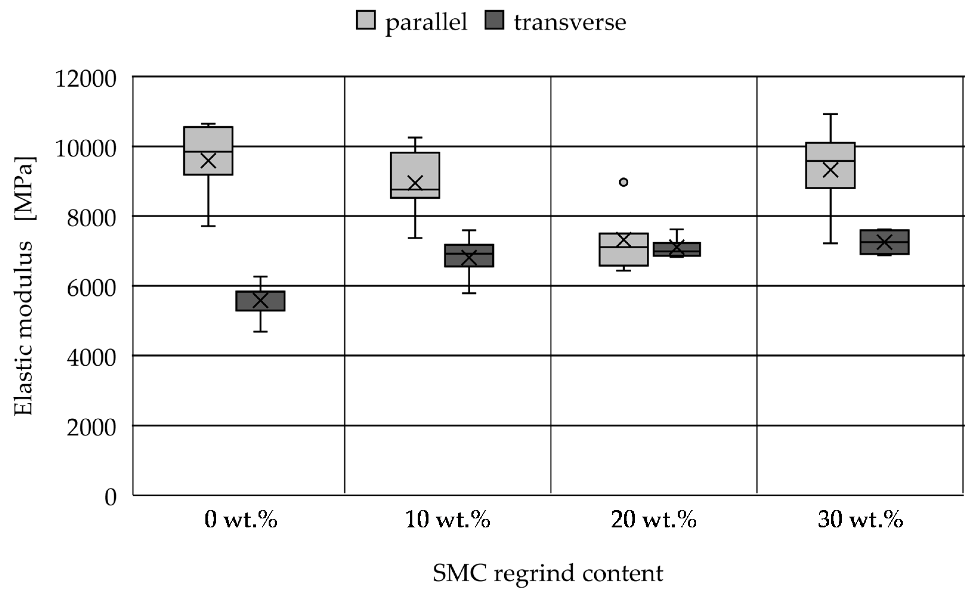
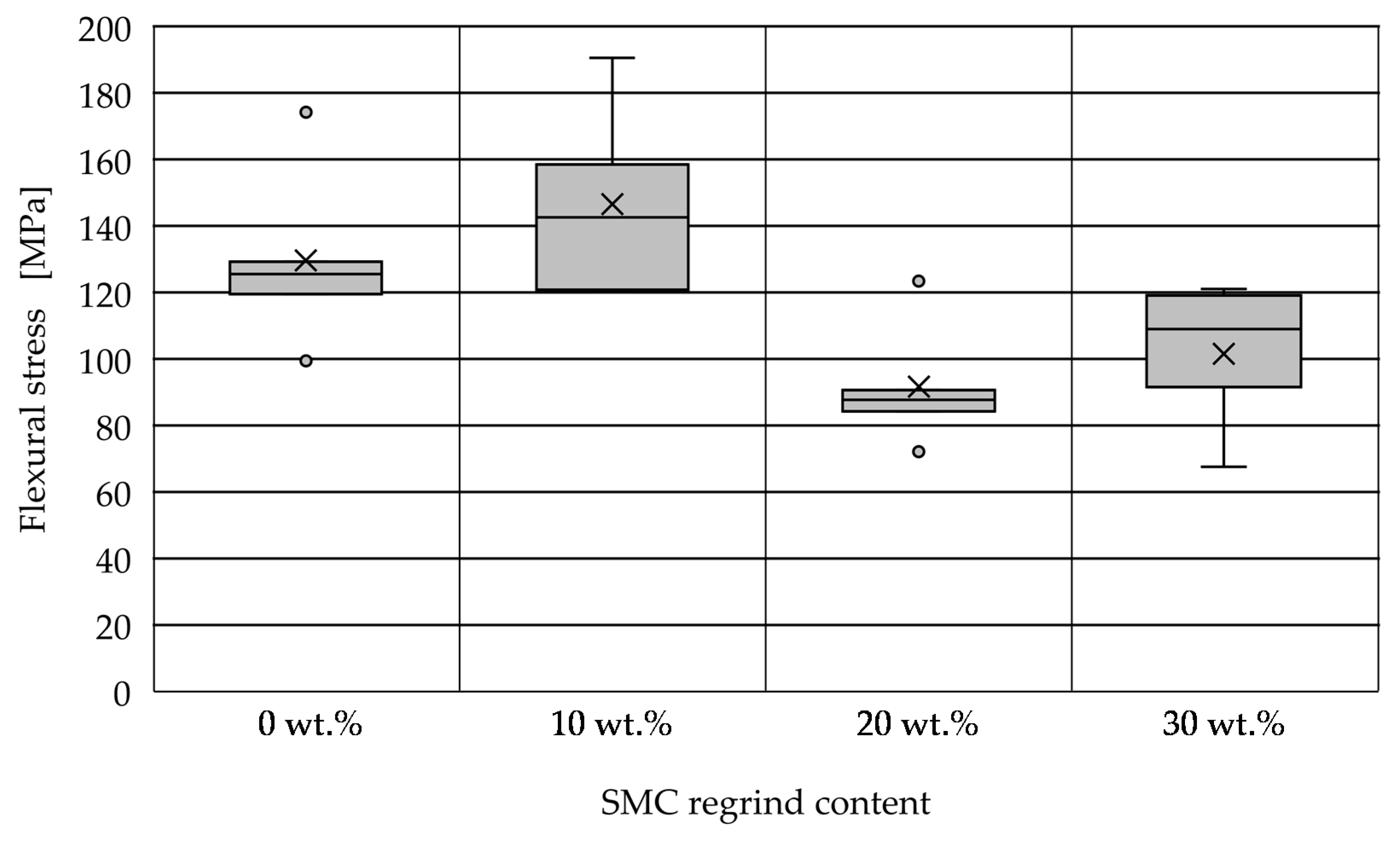
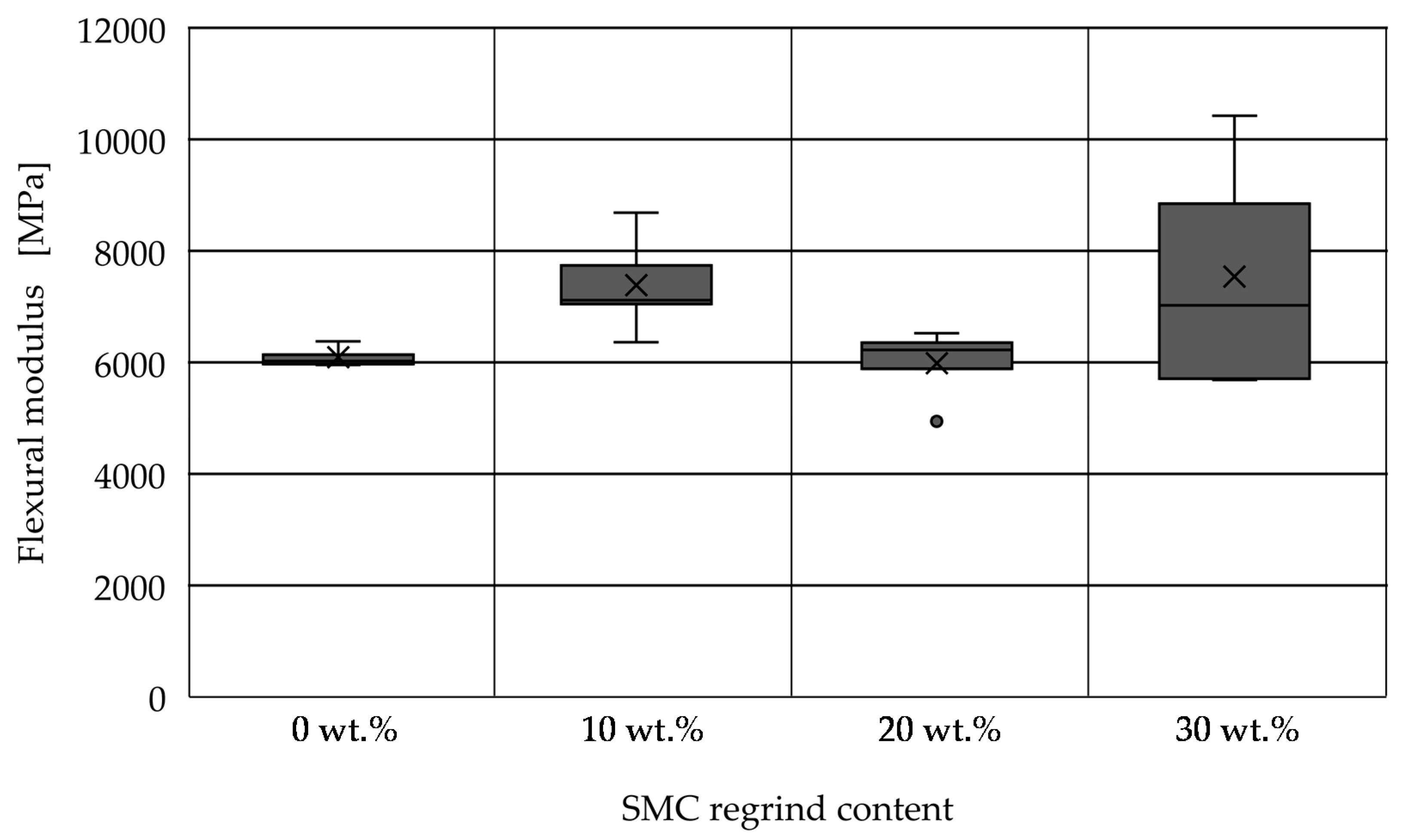
3.3. Mechanical Properties of the SMC Components

The ultimate tensile strength measured parallel and transverse to the direction of flow are depicted in Figure 9.
The parameters differ when distinguishing between samples parallel and transverse to the direction of flow. Samples taken transversely to the flow direction achieve lower strength values than samples taken in parallel direction. In particular, the samples with ωrSMC = 0 wt.% and 30 wt.% show significant differences in the achieved tensile strengths. This indicates that flow-induced anisotropic areas are present in the SMC components due to the pressing process.
It is noticeable that the scatter of the SMC components with ωrSMC = 20 wt.% and 30 wt.% were significantly lower compared with ωrSMC = 0 wt.% and 10 wt.%. The high scattering of the measured values results from the heterogeneous structure of the SMC components and the locally varying glassfiber content [39]. This trend is further promoted due to the manual manufacturing of the SMC preforms.
Looking at the samples taken in parallel direction, the SMC components with ωrSMC = 0% shows the highest tensile strength values. A clear decrease in the tensile strength values is evident for all samples with regrind content. However, the characteristic values for the samples of the SMC components with ωrSMC = 10 wt.%, 20 wt.% and 30 wt.% do not differ significantly.
The characteristic values of the samples taken transversely show a different course. The highest tensile strength values were exhibited by the SMC components with ωrSMC = 10 wt.% and 20 wt.%, which achieved similar values. On the other hand, the tensile strengths of SMC components with ωrSMC = 0 wt.% and 30 wt.% decreased to the same level.
It can be concluded that the properties of the cross direction are overall less influenced by the incorporation of SMC regrind. Due to the compression moulding process, the reinforcing fibers in the component are aligned more markedly in the directional flow. Thus, a possible explanation for the stronger characteristic value decrease in the parallel direction is that the transmission of the fibers to the matrix is inhibited by the substitution of resin with SMC regrind.
As the results of the tensile strength show no clear influence of the SMC regrind, the values of the elastic modulus are analyzed further. The characteristic values of the elastic modulus measured parallel and transverse to the direction of flow are depicted Figure 10.
It can be observed that the samples taken in parallel direction show a decreasing elastic modulus. Thus, an increased content of SMC regrind is connected to a reduction in the stiffness of the SMC. In contrast, the SMC components with ωrSMC = 30 wt.% show a similar elastic modulus to the components with ωrSMC = 0 wt.%.
The samples taken transverse to the direction of flow also show lower characteristic values than samples taken in parallel direction. Furthermore, the transverse samples show a slight increase in the elastic modulus with increasing content of SMC regrind, which indicates that the samples stiffen with increasing levels of recycled material content.
For a closer evaluation, stress–strain curves are depicted in Figure 11. VE-SMC without recyclate content exhibits linear elastic behavior, omitting the degradation of stiffness observed in UP-SMC by Oldenbo et al. at strains of 0.003, and which are attributed to onset damage development in the matrix at this point [25,26].
The addition of the regrind results in the continuous degradation of stiffness with increasing strain levels, which is especially apparent in parallel direction for ωrSMC = 20 wt.% and ωrSMC = 30 wt.%. Oldenbo et al. attribute this behavior to the continuous formation of multiple micro cracks and increased crack density [26].
The flexural stress measured by means of the bending tests are depicted in Figure 12. When looking at the flexural stress, it is noticeable that the SMC components with ωrSMC = 0 wt.% and 10 wt.% reach higher breaking stresses than the components with ωrSMC = 20 wt.% and 30 wt%. The SMC with ωrSMC = 10 wt.% demonstrated the highest values, while the SMC with ωrSMC = 20 wt.% shows the lowest values.
The flexural modulus measured by means of the bending test are depicted in Figure 13. With regard to the flexural modulus, a similar trend of the formulations can be observed, however, it was not found to be as pronounced. The SMC components with ωrSMC = 10 wt.% and 30 wt.% achieve similarly high values. In contrast, the components with ωrSMC = 0 wt.% and 20 wt.% drop to a similar level.
Both matrix failure and fiber/matrix adhesion failure were observed simultaneously in the mechanical tests. The four-point-bending test specimens mainly fractured due to a tensile-stress induced fracture on the tensile-loaded side of the specimens.
Overall, the elastic and flexural moduli determined in the tensile and bending tests, respectively, show a lower overall dependence on the use of SMC regrind. Furthermore, a slight increase in the characteristic values can even be observed (compare Figure 10 and Figure 13). Substituting the resin with the SMC regrind seems to contribute to an overall increase in the stiffness.

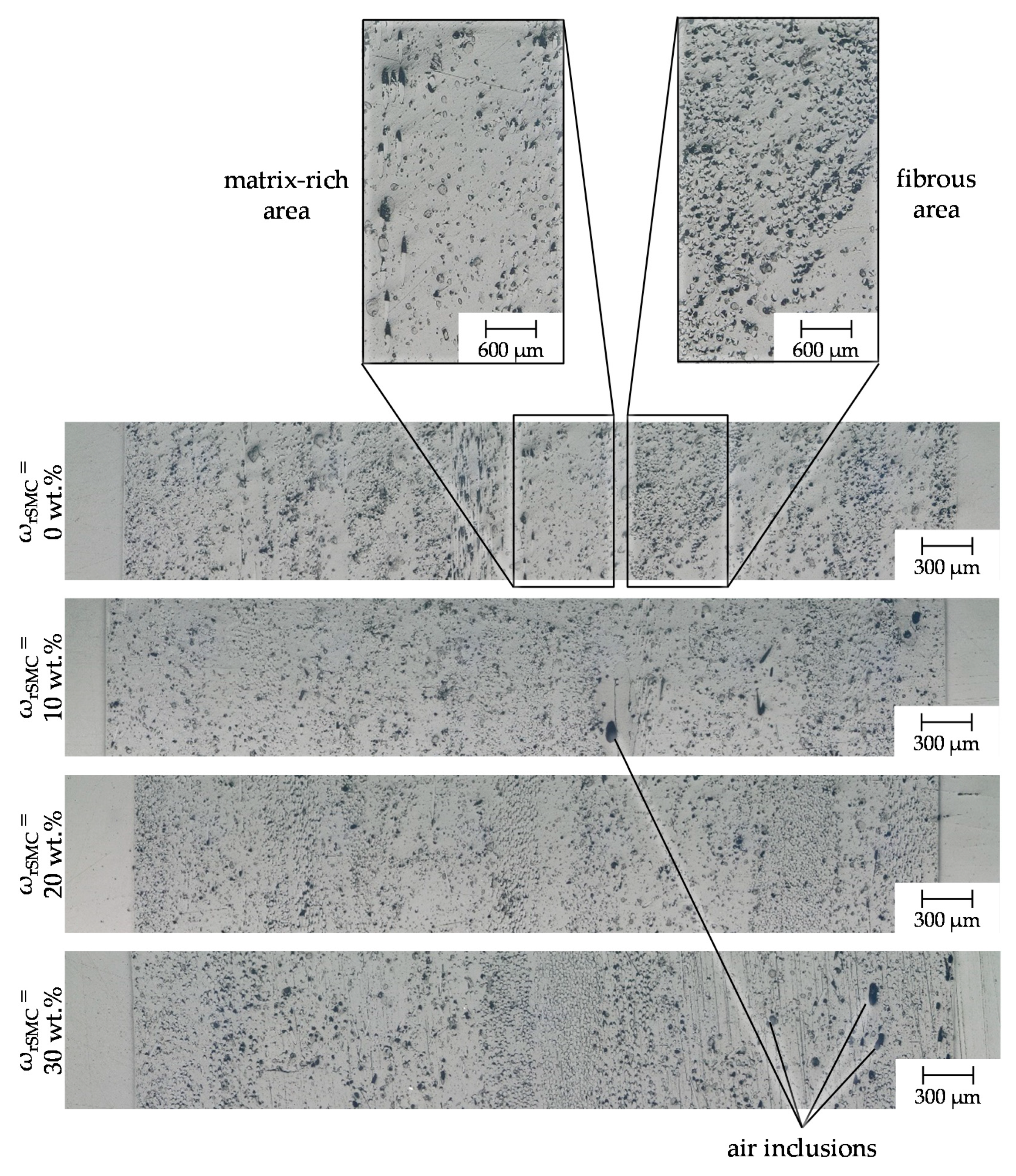
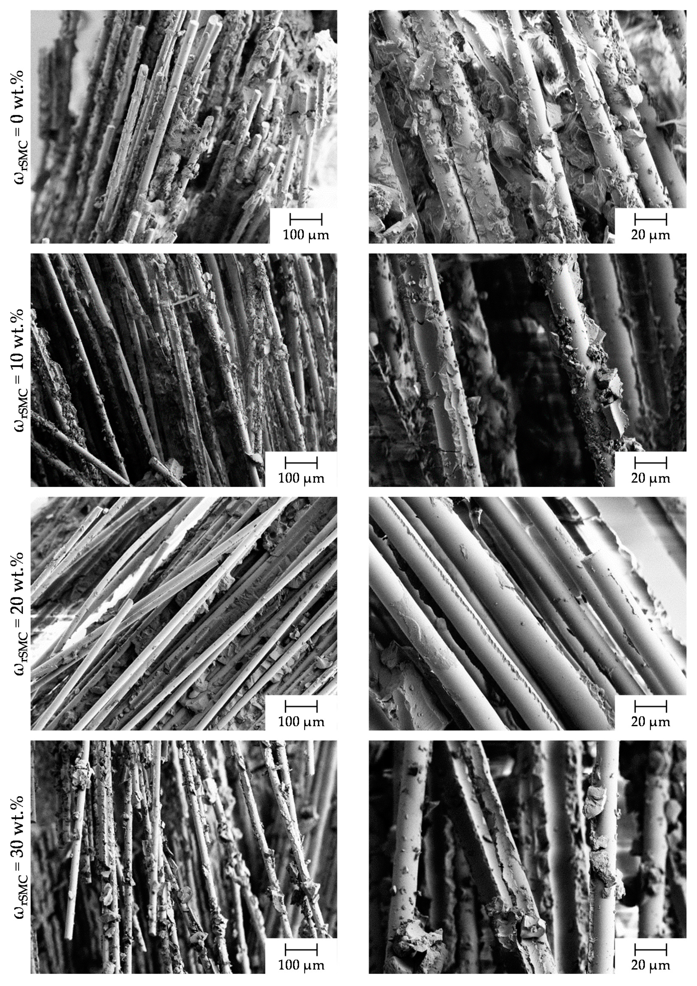
3.4. Microscopic Characteristics of the SMC Components

Figure 14 shows micrographs of the cross section over the thickness of the SMC components with varied SMC regrind content. In all micrographs, both fibrous and matrix-containing areas were observed. A homogeneous distribution over the cross-section is not visible in any sample. However, an inhomogeneity is also to be expected in conventional SMC samples [31]. Moreover, no agglomerates of recycled material were visible in any sample, which can be explained by the use of the dispersion disk and indicates a well-homogenized matrix.
Pores appear in the micrographs as black areas and can be of different sizes. Small pores can be seen in all recipes and are distributed over the cross section. In the microsection with ωrSMC = 30 wt.%, larger pores are visible. Due to the high proportion of recycled material, the basic viscosity of the resin paste increased by almost 40% (measured by plate plate rheometer following DIN EN ISO 3219), making it more difficult for the paste to vent [39]. The increased number of pores can be used to explain the decreased tensile strength (compare Figure 9) as pores or air inclusions represent a quality-reducing feature [35].
The increase in bending properties with a simultaneous drop in tensile characteristics can be explained by the fact that the matrix properties dominate the bending properties of fiber-reinforced plastics more than the tensile properties. Since the fiber-matrix adhesion became deteriorated by the use of recycled material, this also limited the force transmission of the fibers and thus explains the drop in tensile properties.
The SEM images of SMC components with varied SMC regrind content are depicted in Figure 15. Two selected SEM images are representatively shown for each content of SMC regrind. The initiation of cracks in composites may occur by fiber/matrix debonding, matrix/filler debonding and at fiber ends alike [25,39,40,41]. In particular, a poor fiber/matrix adhesion can lead to a loss in strength [35,39].
Looking at the image of the SMC component with ωrSMC = 0 wt.%, a high amount of matrix remained. It is concluded that a strong adhesion of the matrix to the fibers occurred. The image of the SMC component with ωrSMC = 10 wt.% and ωrSMC = 30 wt.% also show a good adhesion of the matrix. However, some blank fibers are visible, which explains the slightly declining characteristic tensile values in a parallel direction when incorporating SMC regrind.
Additionally, a failure of the matrix component can be seen. The image of the SMC component with ωrSMC = 30 wt.% shows a similar fracture pattern to ωrSMC = 10 wt.% with the difference that more blank fibers are visible. Furthermore, it is noticeable that the microsection with ωrSMC = 30 wt.% exhibits an increased number of broken-off areas and overall, decreased fiber-matrix adhesion, which causes the decrease of the mechanical properties in parallel direction.
The image of the SMC component with ωrSMC = 20 wt.% shows a clearly different fracture pattern as mainly blank fibers are visible. This indicates poor fiber/matrix adhesion and goes along with the deterioration of the mechanical properties of the ωrSMC = 20 wt.% components. As the findings do not continue with further increasing of the recyclate content (ωrSMC = 30 wt.%), a plausible explanation for this effect is the manual manufacturing of the SMC preforms.

4. Conclusions

The mechanical recycling of VE-SMC was investigated in this work and the influence of varied SMC regrind content on the mechanical properties of SMC components was systematically analyzed and evaluated.
The mechanical size deduction of SMC results in a recyclate with fiber- and matrix-containing fractions with maximum particle sizes of 0.7 mm. The separation into both fractions is not possible due to remaining fiber/matrix adhesion and the significant variation in fiber length.
The manufacturing of the SMC components on a laboratory-scale for this research permitted us to conduct a valid comparative study, since all SMC preforms are manufactured under the same conditions. However, the manual manufacturing of the SMC preforms resulted in increased air inclusions resulting in relatively high standard deviations.
The substitution of the base resin with recycled material leads to a loss in tensile strength, independent of the proportion of recycled material. The average tensile strength was reduced by up to 30% with the use of recyclate compared to the reference measurements. The reduction in strength does not depend on the proportion of recycled material added and is caused by low fiber/matrix adhesion due to the poor adhesion of the recycled material to the matrix. Furthermore, the increased formation of pores with an increasing proportion of recycled material also has a negative influence on the mechanical properties.
The elastic modulus shows a decreasing tendency as the proportion of recycled material increases, which leads to a reduction in stiffness of the SMC components. The average elastic modulus decreased by up to 23% with the use of recyclate compared to the reference measurements. The samples taken transversely to the direction of flow, however, show a different trend, and the average elastic modulus could be increased by up to 30% with the use of recyclate compared with the reference measurements. This indicates flow-induced anisotropic areas within the SMC components plates.
The average flexural stress and flexural modulus can be increased by 13% and 21%, respectively, by adding 10 wt.% recycled material. However, if the amount of recycled material added is further increased, the bending stress and bending modulus will decrease by up to 29% compared to the reference measurements. Stress–strain curves of the VE-SMC with recyclate content also show a decrease in stiffness with increasing strain not found in virgin VE-SMC.
Failure mechanisms observed are complex and include both matrix and fiber/matrix adhesion failure of varying dominance. With ωrSMC = 10 wt.% the bending characteristics of the SMC components can be slightly increased. In contrast, the tensile properties decrease with the addition of SMC regrind. However, with an increasing mass percentage of SMC regrind, the tensile properties do not drop significantly further.
Overall, the mechanical recycling of SMC and its reuse in new SMC products has a lot of potential and requires further investigation to develop sustainable and profitable processes. The findings of this work provide a first step towards increasing the resource efficiency of SMC and provides researchers and the end user with reference points as to how much recyclate can be used as a substitute for the resin material without significantly reducing the mechanical properties.
The research on VE-SMC subject to particle recycling should be further promoted in the future. In particular, the influence of an SMC regrind contents greater than ωrSMC = 30 wt.% and regrind-dependent failure mechanisms should be thoroughly investigated further, thus achieving both reliable material properties and high re-use ratios. Furthermore, the decrease in tensile strength with ωrSMC ≥ 10 wt.% can in part be attributed to a reduced fiber-matrix adhesion. Thus, the use of wetting and dispersing additives should be investigated in further studies in order to counteract the increase in processing viscosity due to the use of recycled material resulting in better fiber impregnation.
In addition, a fatigue analysis of SMC containing recyclate should be performed, as the interface between virgin material and recyclate has a decisive influence. Moreover, it is conceivable that the thermodynamics of the materials are influences by means of the mechanical recycling and reuse during compression moulding. Thus, differential scanning calorimetry (DSC) investigations could provide further insights into the thermal effects.

Author Contributions

Conceptualization, V.A. and J.N.; methodology, V.A. and J.N.; software, V.A. and J.N.; validation, V.A. and J.N.; formal analysis, V.A., J.N., D.S., R.D. and C.H.; investigation, V.A.; resources, V.A. and J.N.; data curation, V.A. and J.N.; writing—original draft preparation, V.A. and J.N.; writing—review and editing, V.A., J.N., D.S., R.D. and C.H.; visualization, V.A.; supervision, D.S., R.D. and C.H.; project administration, D.S.; funding acquisition, J.N. and D.S. All authors have read and agreed to the published version of the manuscript.

Funding

The investigations set out in this report received financial support from the European Regional Development Fund (No.: EFRE-0801121), to whom we extend our thanks.

Data Availability Statement

The data presented in this study are available on request from the corresponding author.

Acknowledgments

The authors would like to express their gratitude to the Aachen Center for Integrative Lightweight Production (AZL), for the provision of the hydraulic press and the personnel support during the pressing process.

Conflicts of Interest

The authors declare no conflict of interest.

References

  1. Witten, E.; Schuster, A. Der Markt für Glasfaserverstärkte Kunststoffe (GFK) 2019: Marktentwicklungen, Herausforderungen und Chancen; Industrievereinigung Verstärkte Kunststoffe: Frankfurt, Germany, 2019. [Google Scholar]
  2. Witten, E. Aktuelle Entwicklungen und Trends im Composites-Markt. Available online: https://www.weiterbildung.ifam.fraunhofer.de/de/blog/composites-markt.html (accessed on 20 January 2022).
  3. Lässig, R.; Eisenhut, M.; Mathias, A.; Schulte, R.T.; Peters, F.; Kühmann, T.; Waldmann, T.; Begemann, W. Serienproduktion von Hochfesten Faserverbundbauteilen: Persprektiven Für Den Deutschen Maschinen- und Anlagenbau; Roland Berger: Munich, Germany, 2012. [Google Scholar]
  4. Stauber, R.C. Kunststoffe und Kunststofftechnologien für das Automobil der Zukunft. ATZextra 2010, 15, 12–17. [Google Scholar] [CrossRef]
  5. Pickering, S.J. Recycling technologies for thermoset composite materials—current status. Compos. Part A Appl. Sci. Manuf. 2006, 37, 1206–1215. [Google Scholar] [CrossRef]
  6. Prinçaud, M.; Aymonier, C.; Loppinet-Serani, A.; Perry, N.; Sonnemann, G. Environmental Feasibility of the Recycling of Carbon Fibers from CFRPs by Solvolysis Using Supercritical Water. ACS Sustain. Chem. Eng. 2014, 2, 1498–1502. [Google Scholar] [CrossRef] [Green Version]
  7. Vo Dong, P.A.; Azzaro-Pantel, C.; Cadene, A.-L. Economic and environmental assessment of recovery and disposal pathways for CFRP waste management. Resour. Conserv. Recycl. 2018, 133, 63–75. [Google Scholar] [CrossRef] [Green Version]
  8. Job, S.; Leek, G.; Mativenga, P.T.; Oliveux, G.; Pickering, S.; Shuaib, N.A. Composites Recycling: Where Are We Now? Composites UK: Berkhamsted, UK, 2016; Available online: https://compositesuk.co.uk/system/files/documents/Recycling%20Report%202016.pdf (accessed on 20 January 2022).
  9. Meng, F.; Pickering, S.J.; McKechnie, J. An Environmental Comparison of Carbon Fibre Composite Waste End-of-life Options. In Proceedings of the SAMPE Europe Conference 2018, Southampton, UK, 11–13 September 2018. [Google Scholar]
  10. Baur, E.; Harsch, G.; Moneke, M. (Eds.) Werkstoff-Führer Kunststoffe: Eigenschaften, Prüfungen, Kennwerte, 11th ed.; Carl Hanser Verlag: Munich, Germany, 2019. [Google Scholar]
  11. Karuppannan Gopalraj, S.; Kärki, T. A review on the recycling of waste carbon fibre/glass fibre-reinforced composites: Fibre recovery, properties and life-cycle analysis. SN Appl. Sci. 2020, 2, 1–21. [Google Scholar] [CrossRef] [Green Version]
  12. Oliveux, G.; Dandy, L.O.; Leeke, G.A. Current status of recycling of fibre reinforced polymers: Review of technologies, reuse and resulting properties. Prog. Mater. Sci. 2015, 72, 61–99. [Google Scholar] [CrossRef] [Green Version]
  13. Ferdous, W.; Manalo, A.; Yu, P.; Salih, C.; Abousnina, R.; Heyer, T.; Schubel, P. Tensile Fatigue Behavior of Polyester and Vinyl Ester Based GFRP Laminates-A Comparative Evaluation. Polymers 2021, 13, 386. [Google Scholar] [CrossRef]
  14. Ferdous, W.; Ngo, T.D.; Nguyen, K.T.Q.; Ghazlan, A.; Mendis, P.; Manalo, A. Effect of fire-retardant ceram powder on the properties of phenolic-based GFRP composites. Compos. Part B Eng. 2018, 155, 414–424. [Google Scholar] [CrossRef]
  15. Reygrobellet, J.N.; Lopez Cuesta, J.M.; Crespy, A. Incorporation of unsaturated polyester based matrix composites into a PP-PE copolymer for recycling. In International Committee on Composite Materials, Proceedings of the 1999 International Conference on Composite Materials, Paris, France, 5–9 July 1999; ICCM/12TCA: Tours, France, 2000. [Google Scholar]
  16. Winter, H.; Mostert, H.A.M.; Smeets, P.J.H.M.; Paas, G. Recycling of sheet-molding compounds by chemical routes. J. Appl. Polym. Sci. 1995, 57, 1409–1417. [Google Scholar] [CrossRef]
  17. Tesoro, G.; Wu, Y. Chemical Products from Cured Unsaturated Polyester. Adv. Polym. Technol. 1993, 12, 185–196. [Google Scholar] [CrossRef]
  18. Henshaw, J.M.; Han, W.; Owens, A.D. An Overview of Recycling Issues for Composite Materials. J. Thermoplast. Compos. Mater. 1996, 9, 4–20. [Google Scholar] [CrossRef]
  19. Derosa, R.; Telfeyan, E.; Mayes, J.S. Current State of Recycling Sheet Molding Compounds and Related Materials. J. Thermoplast. Compos. Mater. 2005, 18, 219–240. [Google Scholar] [CrossRef]
  20. Petterson, J.; Nilsson, P. Recycling of SMC and BMC in Standard Process Equipment. J. Thermoplast. Compos. Mater. 1994, 7, 56–63. [Google Scholar] [CrossRef]
  21. Inoh, T.; Yokoi, T.; Sekiyama, K.-I.; Kawamura, N.; Mishima, Y. SMC Recycling Technology. J. Thermoplast. Compos. Mater. 1994, 7, 42–55. [Google Scholar] [CrossRef]
  22. Seiler, E.; Teipel, U. Recycling von Kompositbauteilen aus Kunststoffen als Matrixmaterial—ReKomp Abschlussbericht Projektverbund ForCycle—Ressourcenstrategie für Bayern unter Besonderer Berücksichtigung von Sekundärrohstoffen, Nürnberg. 2017. Available online: https://docplayer.org/56978897-Abschlussbericht-recycling-von-kompositbauteilen-aus-kunststoffen-als-matrixmaterial-rekomp-laufzeit.html (accessed on 20 January 2022).
  23. Fette, M.; Hentschel, M.; Santafe, J.G.; Wille, T.; Büttemeyer, H.; Schiebel, P. New Methods for Computing and Developing Hybrid Sheet Molding Compound Structures for Aviation Industry. Procedia CIRP 2017, 66, 45–50. [Google Scholar] [CrossRef]
  24. Oldenbo, M.; Fernberg, S.P.; Berglund, L.A. Mechanical behaviour of SMC composites with toughening and low density additives. Compos. Part A Appl. Sci. Manuf. 2003, 34, 875–885. [Google Scholar] [CrossRef]
  25. Oldenbo, M. Anisotropy and Non-Linear Effects in SMC Composites: From Material Data to FE-Simulation of Structures. Ph.D. Thesis, Luleå University of Technology, Luleå, Sweden, 2004. [Google Scholar]
  26. Palmer, J.; Ghita, O.R.; Savage, L.; Evans, K.E. Recyclate fibres-matrix interface analysis for reuse in sheet moulding compounds (SMC). In Proceedings of the 13th European Conference on Composite Materials, Stockholm, Sweden, 2–5 June 2008. [Google Scholar]
  27. Gortner, F. Bio-Basierte und Nachwachsende Füllstoffe für Dichtereduzierte Sheet Molding Compounds. Ph.D. Thesis, Technische Universität Kaiserslautern, Kaiserslautern, Germany, 2019. [Google Scholar]
  28. Kia, H.G. (Ed.) Sheet Moulding Compounds: Science and Technology; Hanser Gardner Publications: Cincinnati, OH, USA; Munich, Germany, 1993. [Google Scholar]
  29. Orgéas, L.; Dumont, P.J.J. Sheet Moulding Compounds. In Wiley Encyclopedia of Composites; Nicolais, L., Borzacchiello, A., Lee, S.M., Eds.; Wiley Interscience: Hoboken, NY, USA, 2011. [Google Scholar]
  30. Kim, D.-H.; Kim, H.-G.; Kim, H.-S. Design optimization and manufacture of hybrid glass/carbon fiber reinforced composite bumper beam for automobile vehicle. Compos. Struct. 2015, 131, 742–752. [Google Scholar] [CrossRef]
  31. Sambale, H. Fiber Spraying Process for Efficient Preform Production. Available online: https://en.kunststoffe.de/a/article/article-276444 (accessed on 20 January 2022).
  32. Schmidt & Heinzmann GmbH & Co. KG. Fiber Spraying. Available online: https://schmidt-heinzmann.de/fiber-processing/fiber-spraying/ (accessed on 20 January 2022).
  33. Keckl, C. Einfluss der Eindickung von Dichtereduziertem Sheet Moulding Compound auf Die Formteilwelligkeit. Ph.D. Thesis, Karlsruher Institut für Technologie, Karlsruhe, Germany, 2016. [Google Scholar]
  34. Macherauch, E.; Zoch, H.-W. Praktikum in Werkstoffkunde: 95 Ausführliche Versuche aus Wichtigen Gebieten der Werkstofftechnik, 12th ed.; Springer Vieweg: Wiesbaden, Germany, 2014. [Google Scholar]
  35. Erdmann, J. Biobasierte Kunststoffe mit Cellulosefaserverstärkung: Zusammenhänge Zwischen Struktur, Haftung und Mechanischen Eigenschaften. Ph.D. Thesis, Martin-Luther-Universität Halle-Wittenberg, Halle, Germany, 2017. [Google Scholar]
  36. Lamanna, G.; Ceparano, A. Mechanical Characterization of Sheet Moulding Composites for the Automotive Industry. Open Mater. Sci. 2014, 8, 108–113. [Google Scholar] [CrossRef] [Green Version]
  37. Piry, M. Mechanische Auslegung von SMC-Bauteilen und Charakterisierung der Relevanten Werkstoffeigenschaften: Mechanical Dimensioning of SMC-Components and Characterization of the Relevant Material Properties. Ph.D. Thesis, Rheinisch-Westfälische Technische Hochschule Aachen, Aachen, Germany, 2004. [Google Scholar]
  38. Schiebisch, J. Zum Recycling von Faserverbundkunststoffen mit Duroplastmatrix. Ph.D. Thesis, Universität Erlangen-Nürnberg, Erlangen, Germany, 1995. [Google Scholar]
  39. Hour, K.-Y.; Sehitoglu, H. Damage Development in a Short Fiber Reinforced Composite. J. Compos. Mater. 1993, 27, 782–805. [Google Scholar] [CrossRef]
  40. Wang, S.S.; Chim, E.-M. Fatigue Damage and Degradation in Random Short-Fiber SMC Composite. J. Compos. Mater. 1983, 17, 114–134. [Google Scholar] [CrossRef]
  41. Fitoussi, J.; Guo, G.; Baptiste, D. A statistical micromechanical model of anisotropic damage for S.M.C. composites. Compos. Sci. Technol. 1998, 58, 759–763. [Google Scholar] [CrossRef]
Figure 1. Inadequate fiber impregnation at the edges of the preform.
Jcs 06 00084 g001
Figure 2. Schematic illustration of manufacturing of SMC components on a laboratory scale.
Jcs 06 00084 g002
Figure 3. Exemplary manufacturing of SMC Preform with SMC regrind content of ωrSMC = 20 wt.% by manual layout and compaction.
Jcs 06 00084 g003
Figure 4. SMC components with varied SMC regrind content.
Jcs 06 00084 g004
Figure 5. Overview of the experimental design.
Jcs 06 00084 g005
Figure 6. Sawing plan for the tensile and bending specimens of the SMC components.
Jcs 06 00084 g006
Figure 7. 100× magnification of the SMC regrind taken on VHX-600 digital microscope.
Jcs 06 00084 g007
Figure 8. 400× magnification of the fine fraction and 300× magnification of coarse fraction of the SMC regrind taken on VHX-5000 digital microscope.
Jcs 06 00084 g008
Figure 9. Ultimate tensile strength of SMC components with varied SMC regrind content.
Jcs 06 00084 g009
Figure 10. Elastic modulus of SMC components with varied SMC regrind content.
Jcs 06 00084 g010
Figure 11. Stress–strain curves of different test specimens for VE-SMC with varying regrind content.
Jcs 06 00084 g011
Figure 12. Flexural stress of SMC components with varied SMC regrind content.
Jcs 06 00084 g012
Figure 13. Flexural modulus of SMC components with varied SMC regrind content.
Jcs 06 00084 g013
Figure 14. Microsections of SMC components with varied SMC regrind content.
Jcs 06 00084 g014
Figure 15. SEM images of SMC components (cryogenic break) with varied SMC regrind content.
Jcs 06 00084 g015
Table 1. Definition of materials within this work for distinct material identification.
MaterialDefinition
SMC regrindground VE-SMC material (recyclate)
SMC resinmixture of resin, additives and
(varied mass percentages of) SMC regrind
SMC preformglass fibers impregnated with SMC resin
SMC componentscompression moulded SMC
Table 2. Base composition of vinylester-based Sheet Moulding Compounds (VE-SMC) matrix.
ComponentTrade NameParts Per Hundred Resin
Vinylester (VE) resinReichhold Dion 3105692.5
Low profile additive (Solution of a saturated polyester in styrene for shrinkage compensation)Reichhold Norpol 98927.5
Processing additiveBYK BYK-P 90855
Wetting agentBYK BYK-90763
Curing agent
(tert.-Butylperoxy-2-ethylhexylcarbonat)
Nouryon Trigonox 1171.5
Dispersing/anti-shrinkage agent
(Polyethylen (PE) powder)
Axalta Coathylene
HA 1681
2.5
Thickener
(magnesium oxide (MgO) paste)
Luvatol EK 100 KM8
Table 3. Properties of manually manufactured Sheet Moulding Compound (SMC) preforms.
Material PropertiesUnitValue
Density of SMC preformg/cm31.9
Weight per unit areag/m23000
Fiber weight proportion% by weight35
Fiber lengthmm50
SMC regrind share per formulation% by weight0; 10; 20; 30
Table 4. Process parameters of compression moulding process.
Process ParametersUnitValue
Press forcekN2100
Initial mold coverage%50
Position of SMC preform-centered
Pre-heating times45
Curing times300
Compression speedmm/s5
Mold temperature (top/bottom)°C150/135
Table 5. Settings of Z150 for tensile testing.
SettingsUnitValue
Load CellkN150
PreloadN5
Loading Ratemm/min2
Table 6. Settings of Z150 for four-point bending testing.
SettingsUnitValue
Load CellkN100
PreloadN2
Loading Ratemm/min2
Support spanmm66
Loading spanmm22
Radius of the compression finsmm5
Table 7. Comparison of mechanical properties of conventional SMC and manually manufactured SMC determined using DIN EN ISO 527-4.
PropertiesUnitConventional SMC
Fiber Weight Proportion 50 wt.%
Manually Manufactured SMC
Fiber Weight Proportion 35 wt.%
Tensile strength[MPa]134.575.1
Elastic modulus[GPa]10.19.6
Publisher’s Note: MDPI stays neutral with regard to jurisdictional claims in published maps and institutional affiliations.

