Review

Design and Fabrication of Aerogel Composites for Oil Water Separation and Spilled Oil Cleaning

Department of Mechanical Engineering, California State Polytechnic University Pomona, 3801 W Temple Avenue, Pomona, CA 91768, USA
J. Compos. Sci. 2023, 7(3), 95; https://doi.org/10.3390/jcs7030095
Submission received: 29 January 2023 / Revised: 17 February 2023 / Accepted: 28 February 2023 / Published: 3 March 2023
(This article belongs to the Section Composites Manufacturing and Processing)

Abstract

:
Aerogel composites are multicomponent highly porous materials with air as the major dispersed phase. There are many kinds of aerogel composites including synthetic and natural aerogel composites. Aerogel composites have found wide applications in sorption, thermal insulation, vibration damping, and noise control. This mini review focuses on the aerogel composites with oil water separation function for spilled oil cleaning. The design and fabrication of various aerogel composites for oil cleaning are emphasized. The commonly used technologies including in-situ reaction, sol–gel spinning, templating, and self-assembling are introduced. The microstructure control through directional freeze casting, bio-inspired approach, coating, etc., are discussed.

1. Introduction

Aerogel composites are unique in view of their light weight, high porosity, and low thermal conductivity. As a result, they have found wide applications for chemical sorption, energy storage, catalysis, sensing, and thermal insulation. Numerous composite aerogels have been developed. There are two typical categories of aerogel composites for oil-water separation, including synthetic polymer-based and sustainable source-based aerogel composites. Among various synthetic aerogel composites, polyacrylonitrile (PAN) nanofiber with functional polymers, polyvinyl alcohol (PVA), and carbon nanotube (CNT) showed self-cleaning and oil/water separation capabilities [1]. Due to the hydrophobicity, polyurethane (PU) was used to make oil sorption foam for a long time, but the relatively low oil uptake, lack of mechanical strength and poor recyclability limit the application of the polymer-based aerogel for spilled oil cleaning [2]. Polyurethane (PU) and polyvinylidene fluoride (PVDF) composite aerogel showed high absorption capability and good recyclability [3]. Three-dimensional silica [4], graphene-added polystyrene [5], reduced graphene in porous silica [6], coated nickel mesh [7], graphene oxide added carbon nanotube [8], boron nitride and graphene [9], and carbon nitride and oxide graphene added PVDF [10] are some other types of synthesized composite aerogels. In the second category of aerogel composites made from sustainable sources, there are alginate composites [11,12,13], and composites containing agar [14], chitosan [15,16,17,18], cellulose [19,20,21,22,23,24,25] as high absorbents. Many other biomass-based aerogel composites were reviewed in [26]. Several aerogel composites can be produced directly from natural sources. For example, chitosan [27], lignin [28], cotton [29,30,31], pollen grains [32] and silk fibroin [33,34] are some of the naturally derived sources. Recycling fabric from car tire waste for aerogel composite manufacturing was also reported [35]. Aerogel composites are commonly produced from the freeze-drying process. The raw materials for the nanofiber aerogel composites may be prepared through spinning [36]. Post-heat treatment, for example, carbonization [37], is often used to change the compositions of aerogel composites. To improve the surface properties, coatings are generally applied [38].
Oil spilling releases petroleum hydrocarbons into ocean and on land, which causes serious pollution. It could result in disastrous consequences both environmentally and economically. Protecting the ocean, coastline, and land is the driving force for researching the oil/water separation technologies. Previous research has successfully generated relatively low-cost, new aerogel composite materials exhibiting excellent performances on absorbing oil and oil/water separation as will be discussed in greater detail in one of the sections (Section 4) in this review.
This mini review highlights recent progress in design, fabrication, and oil/water separation application of aerogel composites. First, several important manufacturing technologies and structure control of aerogel composites will be introduced. Second, the microstructures of various aerogel composites will be presented. In the third part, the oil/water separation efficiencies of aerogel products will be compared. Lastly, perspectives and concluding remarks will be given.

2. Aerogel Composite Manufacturing Technologies

2.1. Hydrothermal Deposition on Porous Template

Hydrothermal synthesis has been considered as one of the most used methods for nanomaterial preparation [39]. Zhang et al. [7] applied the hydrothermal approach followed by hydrogel modification to produce a composite coating deposited on a nickel mesh. Sodium carboxymethyl cellulose (CMC-Na), K4Fe(CN)6·3H2O, and nickel mesh were used as the starting materials. Other chemicals including ferric chloride hexahydrate and HCl were also used. During the in-situ growth of Prussian blue analogue (PBA) at the surface of Ni mesh (PBA@Ni mesh), hydrothermal method was used as shown in Figure 1 reproduced from [7]. The cleaned Ni mesh was placed into a Teflon-lined stainless-steel autoclave filled with a solution of K4Fe(CN)6·3H2O and HCl. The hydrothermal reaction conditions were set at 95 °C for 5 h. Both nickel etching and in-situ deposition of PBA occurred to generate a rough nickel surface covered with the PBA. Next, the Fe(III)-CMC@PBA@Ni mesh composite was produced by immersing the PBA@Ni mesh into a solution containing 0.1 wt% FeCl3·6H2O and 0.1 wt% CMC-Na solution, respectively. After the process being repeated for multiple times, the composite mesh was air-dried at 45 °C for 3 min to form a hydrophilic Fe(III)-CMC hydrogel layer. The final product, Fe(III)-CMC@PBA@Ni mesh, showed an aerogel composite structure as can be seen from the scanning electron microscopic (SEM) image at the lower right corner of Figure 1 [7].

2.2. Hydrogen Bond Induced Self-Assembling

Shi et al. [40] introduced hydrogen bonding self-assembling to produce materials for aerogel composites. Spherical beads consisting of the partially reduced graphene oxide (prGO) and titanium carbide, MXene (Ti3C2Tx) nanosheets, were constructed by hydrogen bond induced self-assembling. The titanium carbide (Ti3C2Tx MXene) is a novel 2D nanosheet material which can be obtained by selective removal of atoms from the aluminum layers in Ti3AlC2. Practically, it can be performed by etching Ti3AlC2 in HCl and LiF. The Ti3C2Tx MXene compound has large specific surface areas and high electrical conductivity comparable with those of metals. Surface functional groups are ready to be added onto Ti3C2Tx. Therefore, it has been recognized as an effective oil/water separation material for environment cleaning. Graphene oxide (GO) can be easily attached to the hydroxyl groups hanging on the surface of MXene through the abundant hydrogen bonds so that 3D structures can be generated.
The prGO/MXene spherical beads were prepared by a one-step hydrogen bond-induced self-assembly method [40]. Briefly, the GO and MXene suspensions were mixed at various GO/MXene mass ratios. The mixtures were ultrasonically agitated to form homogeneous GO/MXene dispersions. The GO/MXene dispersions were degassed and then poured into the coagulation bath containing 1 wt% cetyltrimethylammonium bromide (CTAB) surfactant to generate the GO/MXene beads. The obtained wet beads were freeze-dried to form aerogel composites. The procedures for making the aerogel composites are schematically illustrated in Figure 2 [40].

2.3. Gas Foaming

This technique uses gas as the foaming agent. During the foaming process, a 2D nanofiber network or mat can be converted into a 3D porous aerogel. In the work performed by Jin et al. [41], polyacrylonitrile (PAN) and itaconic acid (IT) (at a ratio of 99:1) were dissolved into dimethylformamide (DMF) with a concentration of 10 wt%. The solution was electrospun as shown in Figure 3a. The spun nanofibers were in a 2D mat form as sketched in Figure 3b. The 3D foam as illustrated in Figure 3c was fabricated from the electrospun 2D mat in a gas foaming process using 1.0 M sodium borohydride solution as the gas generating agent. The electrospun 2D mat was immersed into the sodium borohydride solution at room temperature for various periods of time (from 5 min to 4 h). Hydrogen gas generated by the hydrolysis of the sodium borohydride caused the 2D fiber mat being converted into 3D foam. The as-formed 3D foam was washed thoroughly with distilled water and frozen to −20 °C followed by freeze drying for 20 h to produce a cylindrical 3D PANIA foam. Following that, the foam was dip-coated with graphene oxide (GO). The GO coated sample was cooled down to −20 °C again followed by freeze drying for 20 h to obtain the foam as shown in Figure 3d. The GO-coated 3D PANIA foam was stabilized in air at 250 °C for 30 min and then carbonized in Ar at 800 °C for 30 min to generate the 3D graphene–carbon nanofiber (G-CNF) foam as schematically shown in Figure 3e [41].

2.4. Vacuum-Assisted Resin Transfer Molding and Particle Leaching

In [42], Zeng et al. prepared polylactic acid (PLA)-based aerogels using the technique involving procedures such as vacuum-assisted resin transfer molding (VARTM), phase separation, solvent extraction, and particle leaching. A chitosan (CS)-coated PLA scaffold was obtained by infiltrating the polymer chloroform solution into a porous preform made from compacted NaCl particles. Here, NaCl served as the porogen. To control the pore structure and porosity of the aerogel composite, the sizes of the NaCl particles and the concentrations of the PLA/chloroform solutions were changed. The physiochemical properties of PLA and CS-coated PLA aerogels were tested. Both PLA and CS-coated PLA showed the porosities of up to 94%. The highest water uptake of the aerogels reached 1200%. Hierarchical open pores with high interconnectivity were observed. The CS-coated PLA aerogel composite possesses mechanical properties and enhanced hydrophilicity compared to those of the pure PLA aerogel [42].
Using the same technique of vacuum infiltration followed by particle leaching, Cui et al. [3] prepared polyvinylidene difluoride/thermoplastic polyurethane (PVDF/TPU) aerogel composites with superoleophilic/hydrophobicity. Three-dimensional porous foam aerogel composites were found very efficient in separation of oils and organics from water. The space holder, NaCl, with various particle sizes was used. The PVDF powder and TPU particles were dissolved in warm 1, 4-dioxane by stirring to obtain an 8% PVDF/TPU/dioxane solution. Then, a small amount of deionized water was added dropwise into the solution. Afterward, the NaCl particles with four size ranges of 0–150 µm, 150–212 µm, 212–300 µm, and 300–425 µm were poured into a plastic mold and compressed into the compact preforms. Then, the PVDF/TPU/dioxane/water mixture solution was infiltrated into the NaCl preform under the assistance of vacuum. After the infiltration, the prepared samples were quickly transferred to a refrigerator and kept overnight at −80 °C. After that, the frozen blocks were immersed into ethanol for 24 h to remove the solvent (1, 4-dioxane). The prepared PVDF/TPU/NaCl specimens were immersed into deionized water for 8 h to remove the NaCl porogen. Finally, the samples underwent freeze drying for 12 h to obtain the 3D porous PVDF/TPU aerogel composites [3].
The scanning electron microscopic (SEM) images of the aerogel composites are shown in Figure 4. All the images reveal the 3D hierarchical porous structures. As shown in Figure 4a, the composite produced by using the NaCl particles with a size range from 300 to 425 µm has the macroscale pore sizes close to that of the particle (at the order of 400 µm). In Figure 4b, the structure shows the macroscale pore sizes at the order of 300 µm. In Figure 4c, the size of macroscale pores decreased to the order of 200 µm. The image in Figure 4d shows the size of macroscale pores of around 150 µm.

2.5. In-situ Growth

Yuan et al. [43] reported the in-situ growth technique for making hierarchical hollow SiO2@MnO2 cubes. These cubes are the materials for making elastic polyurethane (PU) aerogel composites. The aerogel composites were found very effective in removing oil from water. The incorporation of hierarchical hollow SiO2@MnO2 cubes into the PU could change the structure by increasing the surface roughness and specific surface areas of the aerogel composites. Therefore, the hierarchical hollow SiO2@MnO2 cubes can also improve the hydrophobic properties and enhance the adsorption capacity [44]. The mechanical properties of the aerogel composites can be improved as well.
To produce the hierarchical hollow SiO2@MnO2 cubes, a sacrificial iron oxide hard template was synthesized first. Then, silica layer grew in-situ onto the iron oxide to form cubes. After that, the manganese oxide layer was deposited. Lastly, hydrophobic treatment of hierarchical hollow SiO2@MnO2 cubes was conducted [43]. During the synthesis of the cube-shaped iron oxide (hematite) colloidal particles, a mixture of 6.0 M NaOH solution (90 mL) and 2.0 M well-stirred FeCl3·6H2O solution (100 mL) were poured into a glass bottle. After stirring for 15 min, a suspension containing Fe(OH)3 gel formed. The gel was transferred to a Teflon-lined stainless-steel autoclave to be treated at 100 °C for 8 days. After the aging treatment, hematite colloidal (Fe2O3) cubes were generated. The cubes were collected by filtration.
Following the preparation of hematite colloidal (Fe2O3) cubes, the process for depositing SiO2 layer on the iron oxide cubes was shown [43]. In a solution containing tetraethoxysilane (TEOS) and NH3·H2O, the Fe2O3 cubes were coated with silica. The silica-coated cubes were obtained upon the completion of the coating process. Then, the iron oxide cubes as sacrificial templates were removed through the etching in a 4.0 M HCl solution (20 mL) at 100 °C for 24 h. This generated the hollow SiO2 cubes.
The hierarchical hollow SiO2@MnO2 cubes were produced in a hydrothermal process using the previously fabricated hollow SiO2 cubes as hard templates [43,44]. The hollow SiO2 cubes were ultrasonically dispersed into water. Then, KMnO4 was added to form a suspension. This suspension was sealed in a Teflon-lined stainless steel autoclave and heat treated at 150 °C for 48 h. The produced hierarchical hollow SiO2@MnO2 cubes were collected by centrifugation, and washed multiple times using ethanol and deionized water. To improve the hydrophobicity of the hierarchical hollow SiO2@MnO2 cubes, the hydrophobic modification was made on the surface of hierarchical hollow cubes, and the cubes were treated with KH570, a methacryl-functional silane. Briefly, the hierarchical hollow SiO2@MnO2 cubes and KH570 were added into a flask. At pH = 3–4, the aerogel composites were added with ethanol. Ultrasonic dispersing for 15 min was carried out. Continued magnetic stirring was conducted for 2 h. The composites were kept in microwave to maintain 80 °C temperature at the same time. The obtained hydrophobic hierarchical hollow SiO2@MnO2 cubes were filtrated, washed three times with ethanol and deionized water, and collected for further processing polyurethane aerogel composites [43]. Both scanning electron microscopic (SEM) and transmission electron microscopic (TEM) examinations on the hierarchical hollow SiO2 and SiO2@MnO2 cubes were performed, and the imaging results can be found in Figure 5. Figure 5A shows the hollow SiO2 morphology under SEM. The solid crust of silica can barely be seen. Figure 5B reveals the hierarchical hollow SiO2@MnO2 structure under SEM. Ligaments from the deposition of manganese oxide are observed. Figure 5C is a transmission electroscopic (TEM) image revealing the hierarchical hollow SiO2@MnO2 at a relatively low magnification. Fluffy feature of the manganese oxide can be detected. To show the hierarchical feature more clearly, Figure 5D illustrates the hierarchical hollow SiO2@MnO2 at a higher magnification than the previous TEM image of Figure 5C [43]. Transparent nanosheets of MnO2 can be seen at the outer layer of the cubes.

2.6. Vapor Induced Phase Inversion

The vapor-induced phase inversion process involves the exchange of solvents under certain conditions. As shown in Figure 6a [45], the dimethyl sulfoxide (DMSO) solvent in PVDF/DMSO solution was exchanged with water. The photos in Figure 6b illustrate the PVDF aerogel formation process. In a typical experiment, PVDF was added into dimethyl sulfoxide (DMSO) solvent to produce a 10% transparent solution. The solution was placed into a sealed container partially filled with deionized (DI) water. The water vapor induced phase inversion allowed the formation of a PVDF gel. The water containing PVDF gel was frozen. Finally, freeze-drying generated PVDF aerogel. Although this technique was demonstrated using pure PVDF polymer, it is suitable for composite aerogel preparation.

3. Structure and Morphology Control of Aerogel Composites

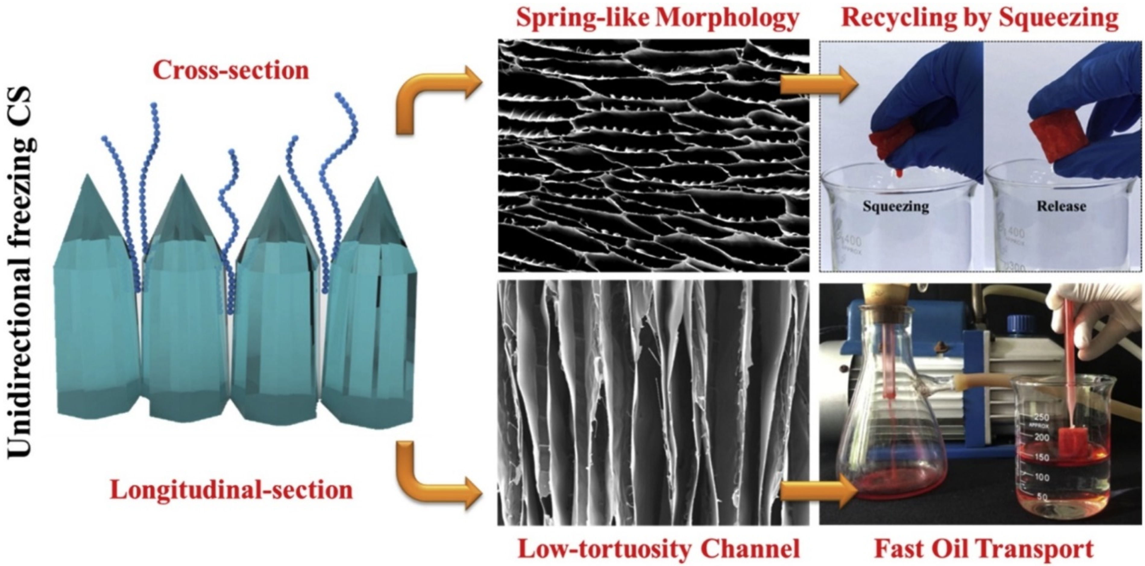
3.1. Directional Freeze Cast Oriented Structures

Directional freezing followed by drying induced structures are shown by a series of SEM images in Figure 7 [13]. The high biocompatibility, low cost, and hydrophobic composite aerogels produced through the directional freezing-drying technology contain chitosan (CS) as the continued phase, the reduced graphene oxide nanosheets (rGO) as the reinforcers and the hydrophobic silica particles/polydimethylsioxane (H-SiO2/PDMS) as the surface modifiers. The images in Figure 7a reveal the unidirectional structure of a pure chitosan (CS) aerogel at different magnifications. The elongated cell wall morphology indicates the solidification direction of the solvent (water). SEM images in Figure 7b show the structure of a chitosan (CS) aerogel composite reinforced by the reduced graphene oxide (rGO) at different magnifications. It seems that the addition of rGO in CS hindered the unidirectional cell wall structure formation. In Figure 7c, the three SEM images at different magnifications demonstrate the cell wall structures with varied orientations. Obviously, the enhanced hydrophobicity from adding H-SiO2/PDMS into the CS/rGO aerogel composite assisted the organization of the cell wall structural domains. In a typical experiment on making such aerogel composites, chitosan (CS) was dissolved in diluted acetic acid solution and stirred for 4 h to obtain a transparent solution with a CS concentration of 2 wt%. Graphene oxide (GO) was dispersed into deionized water at a concentration of 4.0 mg·mL−1 by ultrasonication treatment. The CS solution was mixed with the GO water dispersion at different mass ratios of 10:0, 10:0.5, 10:1, 10:2, 10:3 under continuous magnetic stirring for 12 h. Following that, ultrasonication for 1 h was performed to generate a homogeneous mixture solution. The mixture was transported into a Teflon mode with a diameter of 25 mm and a thickness of 5 mm. Freezing from bottom to top was achieved by placing the Teflon mold on a copper part dipped in liquid nitrogen. The frozen sample was freeze-dried for 72 h to obtain the elongated cell wall structured aerogel. The obtained GO/CS aerogel was fully immersed into the suspension of PDMS and H-SiO2. After extracting the excess solvent with ethanol, the specimen was reduced to generate the rGO/CS-Si aerogel composite with the honeycomb morphology as shown in Figure 7c [45].
Yi et al. [17] produced a chitosan (CS)-methyltrimethoxysilane (MTMS) aerogel composite by the unidirectional freezing method. The advantages of the aerogel composite for oil removal were shown as well. Due to the directional growth of ice crystals along the vertical direction as shown in the left-hand side of Figure 8, a special elongated honeycomb structure with the spring-like morphology was obtained, which can be seen from the SEM image presented in the upper middle section of Figure 8. The cross section of the aerogel composite along the longitudinal direction is featured by well-aligned, low-tortuosity through-channels as revealed by the SEM image located in the lower middle section of Figure 8. Such a special porous structure contributed to the superior mechanical properties of the aerogel composite. This structure is highly durable for large mechanical compression and fast shape recovery, which allows the oil to be squeezed out for recycling as shown by the photos in the upper right part of Figure 8. It was reported that the silylated-CS aerogel composite has a high oil absorption capacity of 63 g/g, along with the excellent recyclability via simple hand squeezing [17]. The unidirectional move in the through-channels provides fast oil transport in the aerogel composite as illustrated by the photos in the lower right part of Figure 8. This allows the CS-MTMS aerogel composite to be installed on portable facilities for fast absorption of oil from water.
Recent development of directional freezing has generated new approaches. Bidirectional freezing technique as shown in [16] represents one of such progresses. A bidirectional freeze-casting square mold with a right-angle copper part and the rest of polystyrene foam was designed for generating dual temperature gradients, for example, “bottom to top” (along z-direction) and “left to right” (along x-direction) as shown in Figure 9a. The copper surface of the cubic mold was placed on a steel plate in contact with the cold source (liquid nitrogen or dry ice ethanol bath). Due to the significant difference in the thermal conductivities between the polystyrene foam and copper, bidirectional freezing was achieved. The device was used to fabricate the aerogel composite consisting of the elastic chitosan coated with a nonflammable and hydrophobic silane coating made of methyltrichlorosilane (MTCS) by chemical vapor deposition (CVD). The highly oriented structures along the dual temperature gradients, as shown by the two SEM images in Figure 9b, were obtained using the bidirectional freeze casting method. Well-aligned lamellae along both x- and z-directions are clearly shown in the SEM images. The pores are in the honeycomb shape consisting of numerous through-channels. These through-channels run all the way from the bottom to the top (along z-direction) or from the left to the right (along x-direction), which facilitates fast oil transport within the aerogel and results in the rapid absorption of oil by the composite. For comparison, the unidirectional freeze casting and ordinary freeze casting set-ups for aerogel composite preparation and resulted aerogel structures were also illustrated by Cao et al. [16]. Figure 9c schematically shows the unidirectional freeze casting to produce aerogel composites. The SEM images in Figure 9d reveal the structures on the cross section (x-y plane) and on the longitudinal section (x-z plane) of the unidirectionally cast aerogel composite. Figure 9e schematically shows the ordinary freeze casting to produce aerogel composites. The SEM images in Figure 9f display the structures on the cross section (x-y plane) and on the longitudinal section (x-z plane) of the commonly freeze cast aerogel composite.

3.2. Stratified Structure

The work performed by Shi et al. [40] introduced the aerogel composites with stratified structures formed from partially reduced graphene oxide (prGO) and MXene (Ti3C2Tx) nanosheets. The aerogel composites are named after the major components. The pure prGO aerogel is known as prGSBDs, while the prGO and MXene aerogel composites are known as prGMSBDs. The prGO to MXene mass ratios of 20:1, 10:1, and 5:1 were adopted from the conditions for processing the aerogel composites, and the obtained aerogel composites are named as prGMSBDs-20, prGMSBDs-10, and prGMSBDs-5, respectively. Both prGSBDs and prGMBDS aerogels were observed by SEM. As shown in Figure 10a–h, all the aerogel specimens have a unique porous structure with stratified feature formed by the single-layered or multi-layered GO and/or Ti3C2Tx nanosheets. The strata or layers in the prGSBDs are relatively loose and the 3D randomly interconnected networks consisting of stacked rGO nanosheets can be seen from the images shown in Figure 10a,e. Numerous large pores are also observed in the two SEM images. Contrary to the prGSBDs, the prGMSBDs aerogel composites show much more ordered strata, indicating that the addition of Ti3C2Tx nanosheets can effectively hinder the aggregation of rGO sheets and prevent them overlapping with each other. This feature is evidently revealed by the two SEM images in Figure 10b,f for the specimen with the relatively low content of Ti3C2Tx nanosheets in the prGMSBDs-20 aerogel composite specimen. With the increase in titanium carbide nanosheet content, the strata in the prGMSBDs-10 aerogel composite become more densely aligned as shown in Figure 10c,g. For the prGMSBDs-5 aerogel composite with even higher content of MXene (Ti3C2Tx) nanosheets, the porous structure shows even densely aligned strata. Much smaller elongated pores can be seen in Figure 10d, while the number of pillars between the nanoplates increased a lot, as illustrated in Figure 10h.

3.3. Fiber Network Structure

Microfabrillated cellulose aerogels (MFCAs) made by Zhou et al. [25] have the fiber network structure as shown in Figure 11. The microfabrillated cellulose (MFC) suspension was isolated from softwood kraft pulp. The pulp was oxidized by 2,2,6,6-tetramethylpiperidine-1-oxyl radical (TEMPO). The TEMPO-oxidized cellulose was fibrillated by a homogenizer. The obtained MFC suspensions (0.2 wt%) were frozen in liquid nitrogen and subjected to freeze-drying using a freeze-dryer. The SEM images in Figure 11a,e at different magnifications clearly show the fiber network structure. To produce aerogel composites, the microfibrillated cellulose aerogel specimens with a diameter of 30 mm and height of 10 mm were immersed into 40 mL ethanol solutions with pre-added 0.5 mL water and different amounts of methyltriethoxysilane (MTES) (1 mL, 2 mL, and 3 mL). The pH of the solutions was adjusted to 2 by adding 99.5% acetic acid, and solutions were stirred at 60 °C for 90 min. After that, the pH of the mixtures was increased to 7.5 with the addition of 25% ammonia and stirred for another 60 min. The obtained aerogel composites were washed with ethanol and methanol to remove the residuals and byproducts from the silanization reactions. The aerogel composites were vacuum-dried at 105 °C for 2 h. The final products of hydrophobic microfabrillated cellulose aerogels (HMFCAs) were obtained. Specifically, the designated names HMFCA-1, HMFCA-2, and HMFCA-3 correspond to the different MTES loadings (1 mL, 2 mL, 3 mL in the solutions as mentioned before).
The morphologies of the aerogel composites (silanization-treated) were illustrated by several sets of SEM images. The images in Figure 11b–d show the cellulose fiber networks and highly porous structures. Through comparison on the porous and network structures of MFCAs and HMFCAs (Figure 11a–d), it was determined that the silanization of MTES did not change the porous structures of the pristine MFCAs. However, with MTES silanization treatment, polysiloxane particles with diameters of approximately 200 nm at the surface of the modified aerogel composites (HMFCAs) were detected. The higher the concentration of MTES, the more polysiloxane nanoparticles as evident by comparing the SEM images in Figure 11f–h. The formation mechanism of the polysiloxane particles was discussed [25]. The little amount of water added in the ethanol solution triggered the hydrolysis of MTES. The hydrolysis-generated silanols reacted with the hydroxyl groups at the surface of MFCAs or other silanols. The reaction between the silanols and the hydroxyl groups led to a covalently bonded silane layer at the surface of the MFCAs, and the generation of the polysiloxane particles was attributed to the self-polymerization of silanols. Elemental composition analysis of the HMFCAs showed that the intensity of Si signal became stronger with the increase in the concentration of the MTES. This indicated the occurrence of the silanization reaction and the successful conversion of pristine MFCAs to the aerogel composites (HMFCAs).

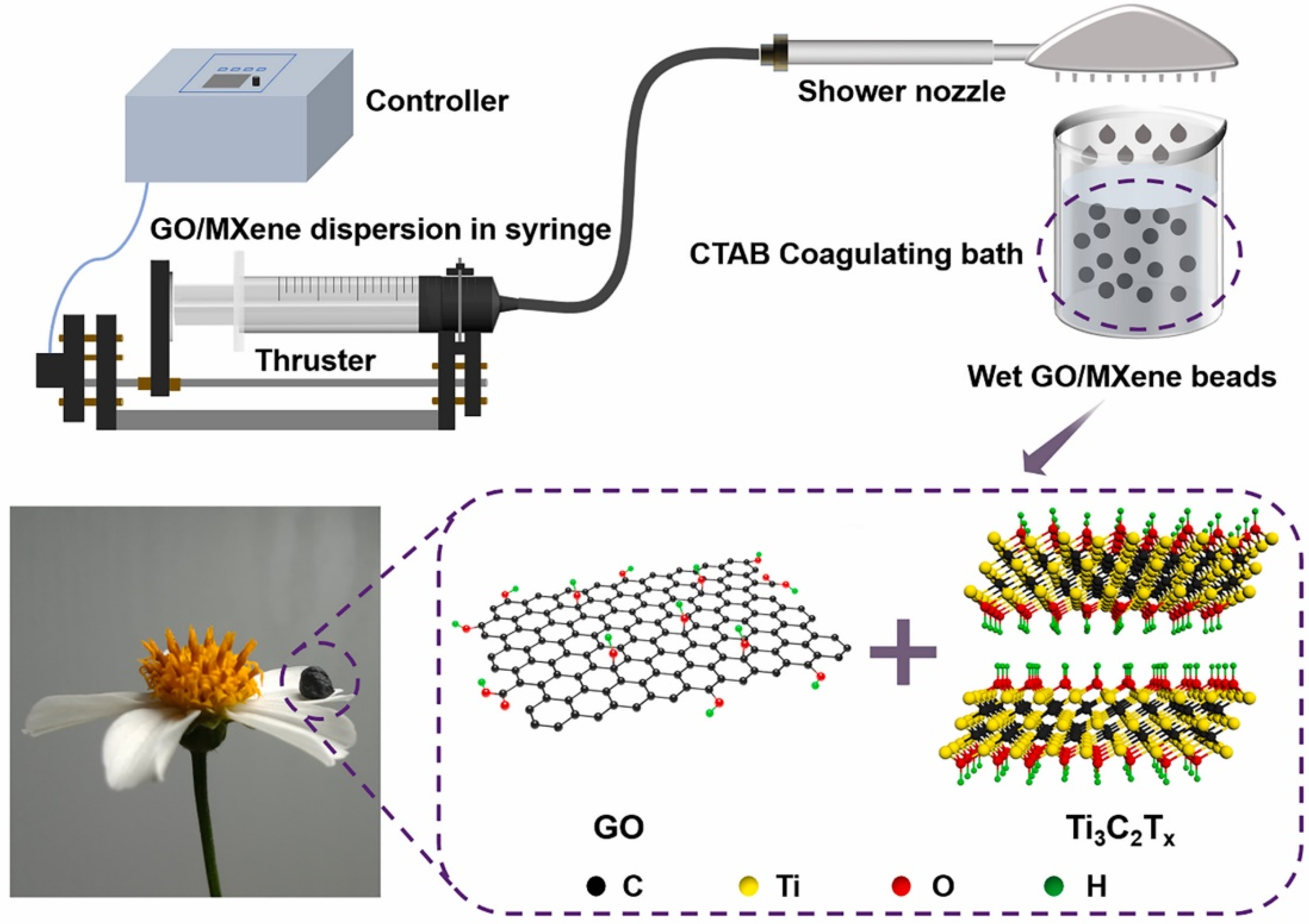
3.4. Beaded Structure

Electrospraying can inject droplets on a substrate, and the dried droplets form beaded structures. He et al. [36] used chloroform (CF) and N,N-dimethylformamide (DMF) as the solvents to produce a polycaprolactone (PCL) solution for electrospraying. PCL electrospraying solutions were prepared by adding 5 wt% PCL in CF/DMF (9:1, v/v). Porous SiO2 aerogel with a pore diameter of approximately 20 nm and particle sizes ranging from 2 to 40 μm was added into the electrospraying solution to increase the hydrophobicity of the PCL/SiO2 aerogel composite. The SiO2 aerogel with different contents (0.1%, 0.3%, 0.5%, 0.7%, and 1.0% w/v) was added into the PCL electrospraying solutions. The obtained PCL/SiO2 aerogel composites were observed by SEM. Figure 12a–f shows the images of the aerogel composites with different SiO2 aerogel contents. For all the specimens, a similar beaded structure can be seen. Hierarchical porous feature is also detected. Such a porous, beaded structure composed of numerous micro–nano beads, nanofibers, and microfibers increased the porosity of the aerogel composites, which can provide more adsorption space for oil clean-up [36].

3.5. Biological Carbon Frame Structure

For the aerogel composites directly derived from woods, leaves, flower pollen, and seeds, the biological structures may be well preserved. In [32], Rong et al. used rapeseed flower pollen grains as the starting materials for aerogel composite preparation. Natural rapeseed flower pollen contains hard exine and tender core with complex biotic components including hemicellulose, cellulose, amino acids, proteins, and nucleic acids. To generate porous carbon with high surface area from pollen grains, the rapeseed flower pollen was washed with ethanol, followed by ultrasonication. The pollen grains were filtered and further washed with deionized water multiple times. In order to preserve the carbon frame, pollen grains were immersed in a mixed solution consisting of formaldehyde and ethanol. Filtering and washing the grains with deionized water were conducted. Dehydration of the pollen grains in 12.0 M sulfuric acid under magnetic stirring at 80 °C for 4 h was performed. The pollen grains were washed with deionized water until the pH reached 7. Air-dried in 80 °C for 20 h, the pollen grains were calcined at 600 °C for 2 h in nitrogen. The carbonized pollen grains containing biological structure are shown in the SEM image located in the lower left part of Figure 13.

4. Oil/Water Separation Efficiency

Traditionally, the surface contact behavior was evaluated by the wettability at the solid/fluid interface (the composite aerogels in this case and the fluid, either oil or water). The wettability of a liquid drop to a solid surface is assessed by the contact angle. A low contact angle corresponds to the wetting state, whereas a high contact angle of larger than 90 degrees represents the unwetted state of the fluid to the solid. In air, the values of contact angles of oil and/or water to a solid surface can be calculated by the Young’s equation [46]. If a solid is immersed into an oil/water emulsion, there are multiple water–oil–solid interfaces. The contact angles still can be determined using the Young’s equation. The surface energy terms should be selected according to the different solid/fluid systems. Since the surface tension of oil is much lower than that of water, most hydrophilic surfaces could be oleophobic at the solid–water–oil interface [47]. For oil/water separation and self-cleaning of oil in water environment, the oleophobic property is needed. For those solids with rough surfaces, Wenzel model [48] and Cassie–Baxter model [49] are suitable for the contact angle calculations. If there is no air trapped at the interfaces, Wentzel model can be used to determine the contact angle of the liquid drop to the rough solid surface using a surface roughness factor [48].
It must be indicated that the Wentzel model only considers the wetting to surface with uniform roughness details which are smaller than the size of the liquid drop. Cassie and Baxter [49] modified the Wentzel model to the solid surface with nonuniformity of roughness. In the Cassie–Baxter model, air bulbs are allowed to be trapped into the liquid–solid interfacial region. As a result, the contact angle can be calculated from the solid–liquid contact area fraction in the region covered by the liquid drop and the air–liquid contact area fraction in the region covered by the liquid drop.
The wetting state of oil and water drops to solid surfaces is tunable by the environment of interfaces, the physical chemistry properties of materials, and the geometrical roughness at the surface of the solids. An oil drop may show low wetting angle at a nanofiber aerogel or membrane surface, but the nanofiber aerogel or membrane itself may be highly oleophobic in water. This is the foundation for achieving the antifouling and self-cleaning surface underwater for aerogel composites. Therefore, the so-called super oleophobic property is needed for efficient oil–water separation in many cases.
In addition to the contact angle, several other parameters were proposed to evaluate the performance of oil–water separation as described by Zhang et al. [50,51]. These parameters include oil permeation flux (J), the oil rejection rate (R), equilibrium adsorption capacities (Qc), oil flux recovery ratio (FRR), the reversible fouling resistance (Rr), and irreversible fouling resistance (Rir). The definitions of these parameters were presented (see [50]). To compare the efficiencies of nanofiber aerogels on separation of oil/water and organics/water, electrospun polyacrylonitrile (PAN), polyaniline coated polyacrylonitrile (PP), and polyaniline and nano molecular brush consisting of polyacrylic acid and polyethyleneimine on polyacrylonitrile (PPPP) were produced [52]. The water contact angle (WCA) is 0o for the three nanofiber aerogel membranes. The underwater oil contact angle (UOCA) for them is over 150°. The WCA and UOCA values indicate the superhydrophiliciy and oloephobicity of these nanofibers. There exist differences in the flow recovery rate (FRR) and flux (J) as shown in Table 1. Obviously, the PPPP nanofiber showed the highest efficiency in separating n-hexane and water because it showed the highest values in FRR, J1 and J2 among the three nanofibers.

5. Conclusions

Recent progress in studies of the aerogel composites for oil absorption and oil/water separation has been presented. For the preparation of aerogel composites, template approach, in situ reaction, sol–gel spinning are matured technologies. Applying coatings to aerogel composites is very effective in changing the surface properties of the composites. Among various coating processes, silanization is especially useful for increasing the hydrophobicity of aerogel composites. For controlling the microstructure of aerogel composites, oriented porous structures offer advantages including fast oil transport, good oil recovery capability, and high mechanical strength during the application in oil/water separation. Therefore, unidirectional and bidirectional freeze casting technologies have been emphasized. There are many research activities focusing on the preparation of sustainable source-derived or bio-based aerogel composites. Such aerogel composites are highly absorptive, non-toxic, and recyclable. Wood, cotton, plant stems and leaves are some of the most studied biomass sources for aerogel composite manufacturing. Any cellulose and lignin generating sources are considered to have value for oil absorption aerogel composites processing. Waste materials including used tire fabrics and recycled papers have been studied for producing oil sorption aerogel composites. In view of the future research directions in the aerogel composite field, carbon aerogel composites with functional additives are promising because of the high temperature stability and recyclability. Further studies on the durability of aerogel composites under various spilled oil cleaning service conditions should be addressed. In addition, energy recovery from the disposal of aerogel composites with absorbed oil should be investigated.

Funding

This research was performed under an appointment to the U.S. Department of Homeland Security (DHS) Science and Technology (S & T) Directorate Office of University Programs Summer Research Team Program for Minority Serving Institutions, administered by the Oak Ridge Institute for Science and Education (ORISE) through an interagency agreement between the U.S. Department of Energy (DOE) and DHS. ORISE is managed by ORAU under DOE contract number DE-SC0014664. All opinions expressed in this paper are the author’s and do not necessarily reflect the policies and views of DHS, DOE or ORAU/ORISE.

Data Availability Statement

The original research data are available through the cited references and their associated links.

Acknowledgments

This research was performed under an appointment to the U.S. Department of Homeland Security (DHS) Science and Technology (S & T) Directorate Office of University Programs Summer Research Team Program for Minority Serving Institutions, administered by the Oak Ridge Institute for Science and Education (ORISE) through an interagency agreement between the U.S. Department of Energy (DOE) and DHS. ORISE is managed by ORAU under DOE contract number DE-SC0014664. All opinions expressed in this paper are the author’s and do not necessarily reflect the policies and views of DHS, DOE or ORAU/ORISE. The support from the DHS Center of Excellence, Arctic Domain Awareness Center (ADAC) at University of Alaska Anchorage, is gratefully acknowledged.

Conflicts of Interest

The author declares no conflict of interest.

References

  1. Ma, W.J.; Jiang, Z.C.; Lu, T.; Xiong, R.H.; Huang, C.B. Lightweight, elastic and superhydrophobic multifunctional nanofibrous aerogel for self-cleaning, oil/water separation and pressure sensing. Chem. Eng. J. 2022, 430, 132989. [Google Scholar] [CrossRef]
  2. Karatum, O.; Bhuiya, M.M.H.; Carroll, M.K.; Anderson, A.M.; Plata, D.L. Life cycle assessment of aerogel manufacture on small and large scales: Weighing the use of advanced materials in oil spill remediation. J. Ind. Ecol. 2018, 22, 1365–1377. [Google Scholar] [CrossRef]
  3. Cui, Z.X.; Wu, J.H.; Chen, J.U.; Wang, X.F.; Si, J.H.; Wang, Q.T. Preparation of 3-D porous PVDF/TPU composite foam with superoleophilic/hydrophobicity for the efficient separation of oils and organics from water. J. Mater. Sci. 2021, 56, 12506–12523. [Google Scholar] [CrossRef]
  4. Liu, P.S.; Yu, H.H.; Hui, F.; Villena, M.A.; Li, X.H.; Lanza, M.; Zhang, Z.J. Fabrication of 3D silica with outstanding organic molecule separation and self-cleaning performance. Appl. Surf. Sci. 2020, 511, 145537. [Google Scholar] [CrossRef]
  5. Alghunaimi, F.I.; Alsaeed, D.J.; Harith, A.M.; Saleh, T.A. Synthesis of 9-octadecenoic acid grafted graphene modified with polystyrene for efficient light oil removal from water. J. Clean. Product. 2019, 233, 946–953. [Google Scholar] [CrossRef]
  6. Thakkar, S.V.; Pinna, A.; Carbonaro, C.M.; Malfatti, L.; Guardia, P.; Cabot, A.; Casula, M.F. Performance of oil sorbents based on reduced graphene oxide-silica composite aerogels. J. Environ. Chem. Eng. 2020, 8, 103632. [Google Scholar] [CrossRef]
  7. Zhang, R.L.; Zhou, Z.P.; Chang, Z.S.; Dai, X.H.; Li, C.; Dai, J.D. Superhydrophilic, underwater superoleophobic and self-cleaning nickel composite mesh via simultaneous acid etching and in-situ growth of Prussian blue analogue for oil-water separation. Colloids Surf. A Physiochem. Eng. Aspect. 2021, 627, 127140. [Google Scholar] [CrossRef]
  8. Kabiri, S.; Tran, D.N.H.; Altalhi, T.; Losic, D. Outstanding adsorption performance of graphene-carbon nanotube aerogels for continuous oil removal. Carbon 2014, 80, 523–533. [Google Scholar] [CrossRef]
  9. Gupta, K.; Joshi, P.; Khatri, O.P. h-BN and graphene-based ultralight hybrid aerogels: Highly efficient sorbent for recovery of hydrocarbon oils and organic solvents. J. Environ. Chem. Eng. 2021, 9, 106788. [Google Scholar] [CrossRef]
  10. Shi, Y.H.; Huang, J.H.; Zeng, G.M.; Cheng, W.J.; Hu, J.L.; Shi, L.X.; Yi, K.X. Evaluation of self-cleaning performance of the modified g-C3N4 and GO based PVDF membrane toward oil-in-water separation under visible-light. Chemosphere 2019, 230, 40–50. [Google Scholar] [CrossRef]
  11. Dai, J.G.; Tian, Q.F.; Sun, Q.Q.; Wei, W.K.; Zhuang, J.D.; Liu, M.Z.; Cao, Z.; Xie, W.Z.; Fan, M.Z. TiO2-alginate composite aerogels as novel oil/water separation and wastewater remediation filters. Compos. Part B Eng. 2019, 160, 480–487. [Google Scholar] [CrossRef]
  12. Zhuang, J.D.; Dai, J.G.; Ghaffar, S.H.; Yu, Y.Y.; Tian, Q.F.; Fan, M.Z. Development of highly efficient, renewable and durable alginate composite aerogels for oil/water separation. Surf. Coat. Technol. 2020, 388, 125551. [Google Scholar] [CrossRef]
  13. Hu, J.; Zhu, J.D.; Ge, S.Z.; Jiang, C.W.; Guo, T.Y.; Peng, T.P.; Huang, T.; Xie, L. Biocompatible, hydrophobic and resilience graphene/chitosan composite aerogel for efficient oil-water separation. Surf. Coat. Technol. 2020, 385, 125361. [Google Scholar] [CrossRef]
  14. Duman, O.; Diker, C.O.; Ugurlu, H.; Tunc, S. Highly hydrophobic and superoleophilic agar/PVA aerogels for selective removal of oily substances from water. Carbohydr. Polym. 2022, 286, 119275. [Google Scholar] [CrossRef]
  15. Zhu, Z.J.; Jiang, L.; Liu, J.; He, S.R.; Shao, W. Sustainable, highly efficient and superhydrophobic fluorinated silica functionalized chitosan aerogel for gravity-driven oil/water separation. Gels 2021, 7, 66. [Google Scholar] [CrossRef]
  16. Cao, M.; Li, S.L.; Cheng, J.B.; Zhang, A.N.; Wang, Y.Z.; Zhao, H.B. Fully bio-based, low fire-hazard and superelastic aerogel without hazardous cross-linkers for excellent thermal insulation and oil clean-up absorption. J. Hazard. Mater. 2021, 403, 123977. [Google Scholar] [CrossRef]
  17. Yi, L.F.; Yang, J.Y.; Fang, X.; Xia, Y.; Zhao, L.J.; Wu, H.; Guo, S.Y. Facile fabrication of wood-inspired aerogel from chitosan for efficient removal of oil from water. J. Hazard. Mater. 2020, 385, 121507. [Google Scholar] [CrossRef]
  18. Saharan, Y.; Singh, J.; Goyat, R.; Umar, A.; Algadi, H.; Ibrahim, A.A.; Kumar, R.; Baskoutas, S. Nanoporous and hydrophobic new chitosan-silica blend aerogels for enhanced oil adsorption capacity. J. Clean. Product. 2022, 351, 131247. [Google Scholar] [CrossRef]
  19. Pirzada, T.; Ashrafi, Z.; Xie, W.Y.; Khan, S.A. Cellulose silica hybrid nanofiber aerogels: From sol-gel electrospun nanofibers to multifunctional aerogels. Adv. Funct. Mater. 2020, 30, 1907359. [Google Scholar] [CrossRef]
  20. Paulauskiene, T.; Uebe, J.; Ziogas, M. Cellulose aerogel composites as oil sorbents and their regeneration. PeerJ 2021, 9, 11795. [Google Scholar] [CrossRef]
  21. Phat, L.N.; Thang, T.Q.; Nguyen, H.C.; Duyen, D.T.M.; Tien, D.X.; Khoa, B.D.D.; Khang, P.T.; Giang, N.T.H.; Nam, H.M.; Phong, M.T.; et al. Fabrication and modification of cellulose aerogels from Vietnamese water hyacinth for oil adsorption application. Korean J. Chem. Eng. 2021, 38, 2247–2255. [Google Scholar] [CrossRef]
  22. Shang, S.S.; Ye, X.; Jiang, X.; You, Q.; Zhong, Y.; Wu, X.D.; Cui, S. Preparation and characterization of cellulose/attapulgite composite aerogels with high strength and hydrophobicity. J. Non-Crystal. Solids 2021, 569, 120922. [Google Scholar] [CrossRef]
  23. Chhajed, M.; Yadav, C.; Agrawal, A.K.; Maji, P.K. Esterified superhydrophobic nanofibrillated cellulose based aerogel for oil spill treatment. Carbohydr. Polym. 2019, 226, 115286. [Google Scholar] [CrossRef] [PubMed]
  24. Zuo, K.M.; Wu, J.J.; Chen, S.Q.; Ji, X.X.; Wu, W.B. Superamphiphobic nanocellulose aerogels loaded with silica nanoparticles. Cellulose 2019, 26, 9661–9671. [Google Scholar] [CrossRef]
  25. Zhou, S.K.; Liu, P.P.; Wang, M.; Zhao, H.; Yang, J.; Xu, F. Sustainable, reusable, and superhydrophobic aerogels from microfibrillated cellulose for highly effective oil/water separation. ACS Sustain. Chem. Eng. 2016, 4, 6409–6416. [Google Scholar] [CrossRef]
  26. Yang, W.J.; Yuen, A.C.Y.; Li, A.; Lin, B.; Chen, T.B.Y.; Yang, W.; Lu, H.D.; Yeoh, G.H. Recent progress in bio-based aerogel absorbents for oil/water separation. Cellulose 2019, 26, 6449–6476. [Google Scholar] [CrossRef]
  27. Zhang, T.; Yuan, D.S.; Guo, Q.; Qiu, F.X.; Yang, D.Y.; Ou, Z.P. Preparation of a renewable biomass carbon aerogel reinforced with sisal for oil spillage clean-up: Inspired by green leaves to green Tofu. Food Bioprod. Process. 2019, 114, 154–162. [Google Scholar] [CrossRef]
  28. Meng, Y.; Liu, T.L.; Yu, S.S.; Cheng, Y.; Lu, J.; Wang, H.S. A lignin-based carbon aerogel enhanced by graphene oxide and application in oil/water separation. Fuel 2020, 278, 118376. [Google Scholar] [CrossRef]
  29. Xu, B.; Ding, J.E.; Feng, L.; Ding, Y.Y.; Ge, Y.F.; Cai, Z.S. Self-cleaning cotton fabrics via combination of photocatalytic TiO2 and superhydrophobic SiO2. Surf. Coat. Technol. 2015, 262, 70–76. [Google Scholar] [CrossRef]
  30. Cao, C.Y.; Ge, M.Z.; Huang, J.Y.; Li, S.H.; Deng, S.; Zhang, S.N.; Chen, Z.; Zhang, K.Q.; Al-Deyab, S.S.; Lai, Y.K. Robust fluorine-free superhydrophobic PDMS-ormosil@fabrics for highly effective self-cleaning and efficient oil-water separation. J. Mater. Chem. A 2016, 4, 12179–12187. [Google Scholar] [CrossRef]
  31. Dwivedi, P.; Vijayakumar, R.P.; Chaudhary, A.K. Synthesis of UMCNO-cotton fabric and its application in wastewater treatment. Cellulose 2019, 27, 969–980. [Google Scholar] [CrossRef]
  32. Rong, J.; Qiu, F.X.; Zhang, T.; Zhang, X.Y.; Zhu, Y.; Xu, J.C.; Yang, D.Y.; Dai, Y.T. A facile strategy toward 3D hydrophobic composite resin network decorated with biological ellipsoidal structure rapeseed flower carbon for enhanced oils and organic solvents selective absorption. Chem. Eng. J. 2017, 322, 397–407. [Google Scholar] [CrossRef]
  33. Nong, Y.L.; Ren, Y.W.; Wang, P.; Zhou, M.; Yu, Y.Y.; Yuan, J.G.; Xu, B.; Wang, Q. A facile strategy for the preparation of photothermal silk fibroin aerogels with antibacterial and oil-water separation abilities. J. Colloid Interface Sci. 2012, 603, 518–529. [Google Scholar] [CrossRef]
  34. Shome, A.; Moses, J.C.; Rather, A.M.; Mandal, B.B.; Manna, U. Unconventional and facile fabrication of chemically reactive silk fibroin sponges for environmental remediation. ACS Appl. Mater. Interfaces 2021, 13, 24258–24271. [Google Scholar] [CrossRef]
  35. Thai, Q.B.; Le-Cao, K.; Nguyen, P.T.T.; Le, P.K.; Phan-Thien, N.; Duong, H.M. Fabrication and optimization of multifunctional nanoporous aerogels using recycled textile fibers from car tire wastes for oil-spill cleaning, heat-insulating and sound absorbing applications. Colloids Surf. A-Physiochem. Eng. Aspect. 2021, 628, 127363. [Google Scholar] [CrossRef]
  36. He, N.N.; Li, L.L.; Chen, J.Q.; Zhang, J.H.; Liang, C. Extraordinary superhydrophobic polycaprolactone-based composite membrane with an alternated micro-nano hierarchical structure as an eco-friendly oil/water separator. ACS Appl. Mater. Interfaces 2021, 13, 24117–24129. [Google Scholar] [CrossRef]
  37. Li, L.X.; Hu, T.; Li, A.; Zhang, J.P. Electrically conductive carbon aerogels with high salt-resistance for efficient solar-driven interfacial evaporation. ACS Appl. Mater. Interfaces 2020, 12, 32143–32153. [Google Scholar] [CrossRef]
  38. Wang, B.; Peng, S.; Wang, Y.C.; Li, X.X.; Zhang, K.M.; Liu, C.Y. A non- fluorine method for preparing multifunctional robust superhydrophobic coating with applications in photocatalysis, flame retardance, and oil- water separation. New J. Chem. 2019, 43, 7471–7481. [Google Scholar] [CrossRef]
  39. Gan, Y.X.; Jayatissa, A.H.; Yu, Z.; Chen, X.; Li, M.H. Hydrothermal synthesis of nanomaterials. J. Nanomater. 2020, 2020, 8917013. [Google Scholar] [CrossRef] [Green Version]
  40. Shi, Y.Q.; Sun, M.N.; Liu, C.A.; Fu, L.B.; Lv, Y.C.; Feng, Y.Z.; Huang, P.; Yang, F.Q.; Song, P.A.; Liu, M.H. Lightweight, amphipathic and fire-resistant prGO/MXene spherical beads for rapid elimination of hazardous chemicals. J. Hazard. Mater. 2022, 423, 127069. [Google Scholar] [CrossRef]
  41. Jin, X.; Al-Qatatsheh, A.; Subhani, K.; Salim, N.V. Biomimetic and flexible 3D carbon nanofiber networks with fire-resistant and high oil-sorption capabilities. Chem. Eng. J. 2021, 412, 128635. [Google Scholar] [CrossRef]
  42. Zeng, S.; Cui, Z.X.; Yang, Z.Q.; Si, J.H.; Wang, Q.T.; Wang, X.F.; Peng, K.P.; Chen, W.Z. Characterization of highly interconnected porous poly(lactic acid) and chitosan-coated poly(lactic acid) scaffold fabricated by vacuum-assisted resin transfer molding and particle leaching. J. Mater. Sci. 2016, 51, 9958–9970. [Google Scholar] [CrossRef]
  43. Yuan, D.S.; Zhang, T.; Guo, Q.; Qiu, F.X.; Yang, D.Y.; Ou, Z.P. A novel hierarchical hollow SiO2@MnO2 cubes reinforced elastic polyurethane foam for the highly efficient removal of oil from water. Chem. Eng. J. 2017, 327, 539–547. [Google Scholar] [CrossRef]
  44. Yuan, D.S.; Zhang, T.; Guo, Q.; Qiu, F.X.; Yang, D.Y.; Ou, Z.P. Recyclable biomass carbon@SiO2@MnO2 aerogel with hierarchical structures for fast and selective oil-water separation. Chem. Eng. J. 2018, 351, 622–630. [Google Scholar] [CrossRef]
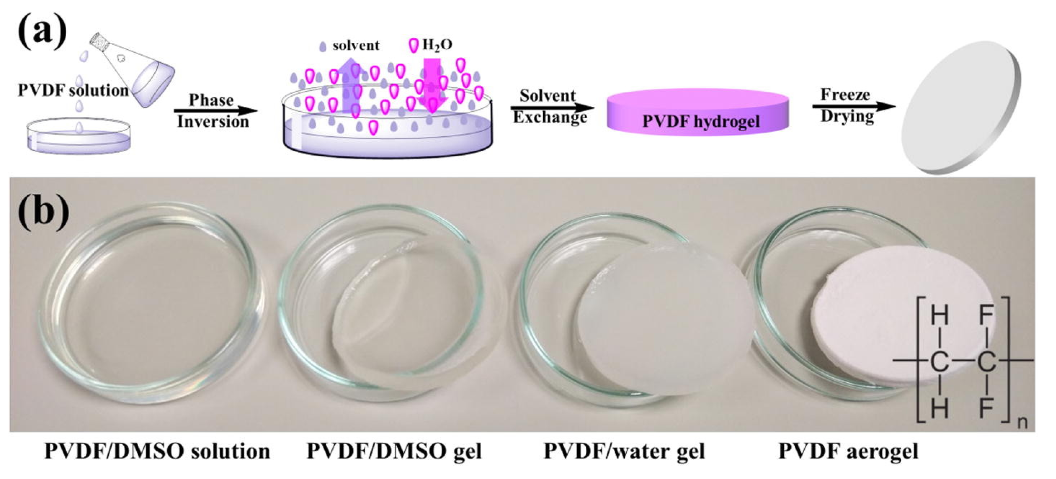
  45. Chen, X.L.; Liang, Y.N.; Tang, X.Z.; Shen, W.M.; Hu, X. Additive-free poly (vinylidene fluoride) aerogel for oil/water separation and rapid oil absorption. Chem. Eng. J. 2017, 308, 18–26. [Google Scholar] [CrossRef]
  46. Young, T. An essay on the cohesion of fluids. Philos. Trans. R. Soc. Lond. 1805, 95, 65–87. [Google Scholar] [CrossRef]
  47. Jung, Y.C.; Bhushan, B. Wetting behavior of water and oil droplets in three-phase interfaces for hydrophobicity/philicity and oleophobicity/philicity. Langmuir 2009, 25, 14165–14173. [Google Scholar] [CrossRef]
  48. Wenzel, R.N. Resistance of solid surfaces to wetting by water. Ind. Eng. Chem. 1936, 28, 988–994. [Google Scholar] [CrossRef]
  49. Cassie, A.B.D.; Baxter, S. Wettability of porous surfaces. Trans. Faraday Soc. 1944, 40, 546–551. [Google Scholar] [CrossRef]
  50. Zhang, J.Q.; Xue, Q.Z.; Pan, X.L.; Jin, Y.K.; Lu, W.B.; Ding, D.G.; Guo, Q.K. Graphene oxide/polyacrylonitrile fiber hierarchical-structured membrane for ultra-fast microfiltration of oil-water emulsion. Chem. Eng. J. 2017, 307, 643–649. [Google Scholar] [CrossRef]
  51. Zhang, J.Q.; Hui, L.; Liu, P.Z.; Liu, X.L.; Gan, S.P.; Xiao, C.; Lei, Z.; Wei, B.J.; Xue, Q.Z. Recyclable superhydrophilic meshes with scalable and robust coating for separating oily wastewater. Appl. Surf. Sci. 2022, 602, 154396. [Google Scholar] [CrossRef]
  52. Li, H.; Zhang, J.Q.; Zhu, L.; Liu, H.L.; Yu, S.F.; Xue, J.W.; Zhu, X.; Xue, Q.Z. Reusable membrane with multifunctional skin layer for effective removal of insoluble emulsified oils and soluble dyes. J. Hazard. Mater. 2021, 415, 125677. [Google Scholar] [CrossRef]
Figure 1. Illustration and SEM image showing hydrothermal deposition and hydrogel modification of the Fe(III)-CMC@PBA composite coating on nickel mesh for oil water separation. Reproduced with permission from [7], ©2021 Elsevier B.V.
Jcs 07 00095 g001
Figure 2. Schematic showing the hydrogen bond-induced self-assembling of beads for oil/water separation aerogel composite preparation. CTAB stands for the cetyltrimethylammonium bromide surfactant. Reproduced with permission from [40], ©2021 Elsevier B.V.
Jcs 07 00095 g002
Figure 3. Illustration of gas foaming method for aerogel composite preparation: (a) electrospinning set-up, (b) 2D nanofiber mat, (c) 3D nanofiber foam, (d) graphene oxide coated 3D fiber foam, (e) carbonized aerogel composite. Reproduced with permission from [41], ©2021 Elsevier B.V.
Jcs 07 00095 g003
Figure 4. SEM images of vacuum filtration and particle leaching generated PVDF/TPU aerogel composites using different sizes of NaCl particles: (a) 300–425 µm, (b) 212–300 µm, (c) 150–212 µm and (d) 0–150 µm. Reproduced from [3], ©2021 the authors.
Jcs 07 00095 g004
Figure 5. Electron microscopic images of (A) hollow SiO2 under SEM; (B) hierarchical hollow SiO2@MnO2 under SEM; (C) hierarchical hollow SiO2@MnO2 at low magnification under TEM; (D) hierarchical hollow SiO2@MnO2 at high magnification under TEM. Reproduced with permission from [43], ©2021 Elsevier B.V.
Jcs 07 00095 g005
Figure 6. Illustration of the phase inversion method for aerogel fabrication: (a) schematic showing the solvent exchange and phase inversion process and (b) digital photos showing sample phase changes and aerogel formation during the fabrication. Reproduced with permission from [45], ©2017 Elsevier B.V.
Jcs 07 00095 g006
Figure 7. SEM images with different magnification of CS (a), GO/CS (b) and rGO/CS-Si aerogel (c). Reproduced with permission from [13], ©2020 Elsevier B.V.
Jcs 07 00095 g007
Figure 8. Schematic of unidirectional freezing (left), SEM images of a CS-MTMS aerogel composite specimen along transverse and longitudinal cross sections (middle), and the photos showing oil removal using the aerogel composite (right). Reproduced with permission from [17], ©2019 Elsevier B.V.
Jcs 07 00095 g008
Figure 9. (a) Schematic illustration of bidirectional freeze casting aerogel composites, (b) SEM images for the cross section (x-y plane) and longitudinal section (x-z plane) of the bidirectionally freeze cast aerogel composite, (c) schematic illustration of unidirectional freeze casting aerogel composites. (d) SEM images for the cross section (x-y plane) and longitudinal section (x-z plane) of the unidirectionally cast aerogel composite. (e) Schematic illustration of the ordinary freeze casting aerogel composite. (f) SEM images for the cross section (x-y plane) and longitudinal section (x-z plane) of the commonly freeze cast aerogel composite. Reproduced with permission from [16], ©2020 Elsevier B.V.
Jcs 07 00095 g009
Figure 10. SEM images of the aerogel composites with stratified structures: (a,e) prGSBDs, (b,f) prGMSBDs-20, (c,g) prGMSBDs-10 and (d,h) prGMSBDs-5. Reproduced with permission from [40], ©2021 Elsevier B.V.
Jcs 07 00095 g010
Figure 11. SEM images of the aerogel composites: (a,e) MFCAs, (b,f) HMFCA-1, (c,g) HMFCA-2, (d,h) HMFCA-3. Reprinted with permission from [25]. Copyright ©2016 American Chemical Society.
Jcs 07 00095 g011
Figure 12. Morphology of the PCL/SiO2-the composites with different contents of SiO2 aerogel: (a) PCL; (b) 0.1% SiO2 aerogel; (c) 0.3% SiO2 aerogel; (d) 0.5% SiO2 aerogel; (e) 0.7%; and (f) 1.0% SiO2 aerogel. Reprinted with permission from [36]. Copyright ©2021 American Chemical Society.
Jcs 07 00095 g012
Figure 13. Photos and SEM image showing the carbon aerogel composite made from rapeseed flower pollen grains. The SEM image reveals the biological structure derived from that of the original pollen grains. Reproduced with permission from [32], ©2017 Elsevier B.V.
Jcs 07 00095 g013
Table 1. The flow recovery rate (FRR) and flux (J) tested using n-hexane/water emulsion. Adapted and modified with permission from [52], ©2021 Elsevier B.V.
NanofiberPANPP (PANi Coated PAN)PPPP (PANi, PAA, and PEI on PAN)
FRR(%)7.956.295.9
J1(L/m2/h/bar)95321863071
J2(L/m2/h/bar)66510271827
Note: J1 without surfactant in emulsion, J2 with the addition of surfactant in emulsion.
Disclaimer/Publisher’s Note: The statements, opinions and data contained in all publications are solely those of the individual author(s) and contributor(s) and not of MDPI and/or the editor(s). MDPI and/or the editor(s) disclaim responsibility for any injury to people or property resulting from any ideas, methods, instructions or products referred to in the content.

