Article

Hardness Measurements and Interface Behavior of SiC-B4C-Si Multiple Phase Particulate Composites Made with Melt Infiltration and Additive Manufacturing

1
Oak Ridge National Laboratory, Manufacturing Science Division, Oak Ridge, TN 37830, USA
2
Oak Ridge National Laboratory, Materials Science and Technology Division, Oak Ridge, TN 37830, USA
3
Center for Nanophase Materials Sciences, Oak Ridge National Laboratory, Oak Ridge, TN 37830, USA
*
Author to whom correspondence should be addressed.
J. Compos. Sci. 2023, 7(4), 172; https://doi.org/10.3390/jcs7040172
Submission received: 11 March 2023 / Revised: 10 April 2023 / Accepted: 12 April 2023 / Published: 20 April 2023
(This article belongs to the Topic Progress in Si-Based Ceramic and Composites)

Abstract

:
Reaction-bonded SiC-B4C-Si ceramic composites were binder jet 3D-printed and subsequently pressureless-melt-infiltrated with molten Si. The addition of B4C aided the Si infiltration to produce a highly dense composite. The microstructures and phases of these composites were examined. The measured hardness values of each constituent with Vickers and nanoindentation matched the bulk values, and the macro-hardness values with Knoop and spherical indentation represented the bulk, composite hardness values of all three phases together, which was close to a rule of mixtures value. For particulate-based composites, this is a significant finding. The interfacial bonds of SiC and Si were imaged using scanning transmission electron microscopy to view intimacy, whereas the crack propagation was examined with carefully placed indents. This work demonstrated that pressureless melt infiltration with a reactive particle provides a method to shape non-wetting reaction-bonded ceramic composites with limited shrinkage and high density and provides insights into the mechanical behavior with numerous indentation techniques.

Graphical Abstract

1. Introduction

Composites with high hardness, wear resistance, and high temperature capability are difficult to process into dense material. The near net shape sintering to full density of covalently bonded ceramics such as SiC and B4C is difficult. Reaction bonding is a potential alternative process, forming a composite with intimate bonds between the matrix and the particles. Reaction bonding works best when the molten material wets the reinforcement material, facilitating intimate contact between the matrix and reinforcement. A resultant fully dense composite is possible [1].
Reaction-bonded SiC is accomplished by melting Si into the carbon preforms, allowing for a reaction to form SiC [2,3,4,5,6,7]. However, because of the large amount of exothermic energy released and the large volumetric increase, this method is usually not performed with bulk carbon preforms. Reaction bonding of SiC itself requires some carbon addition because the wetting of pure SiC with pure molten Si is poor, with a contact angle of >40° [8,9]. However, SiC-Si composites can be processed with gas pressure infiltration, which adds difficulty in manufacturing, or infiltrated with Si alloys that contain activator metals to improve the wetting, which introduces extra material [10,11]. One study showed that SiC can be infiltrated with molten Si under a high vacuum and with high-purity materials, but reaching the required levels of vacuum in tube furnaces is difficult and expensive [12]. SiC can be densified with carbon sources and Si infiltration, but the approaches are also more expensive and time-consuming. The addition of a wetting agent that contributes to the hardness (such as B4C) of the composite aims to address both of these challenges.
Typically, preforms produced from B4C can form fully dense composites by reaction bonding when infiltrated with Si because the contact angle of B4C and pure molten Si is <20°, facilitating favorable wetting and complete infiltration [13,14,15]. However, the reaction-bonded piece usually contains unreacted Si, a ternary carbide B12(B, C, Si)3 phase, and SiC in the form of platelets and whiskers [16,17,18,19,20]. Since some SiC will form through the reaction of B4C and Si, SiC particles have been added to the B4C preform to prevent the formation of platelets and whiskers by encouraging the formation of new SiC on the outer parts of existing SiC particles from liquid Si and free carbon, called the rim [21]. Composites produced by combining carbide powders with silicon infiltration show promise, with lower costs and fewer manufacturing steps, but additive manufacturing or 3D printing processes can increase the throughput and lower the costs even further, while adding to the geometric complexity for wear parts [22].
The binder jet 3D printing process uses a polymer binder sprayed into a powder bed and subsequent powder dropping and rolling until the part is shaped, and the resulting product is a loosely bound powder part [23]. Additionally, reaction-bonded SiC-based ceramics have been produced by the infiltration of porous printed preforms. For example, porous carbon was printed with a furfuryl binder, pyrolyzed, and infiltrated with Si to form reaction-bonded SiC-Si composites [24]. Moreover, the reaction bonding of binder jet 3D-printed SiC with a phenolic binder and extra phenolic infiltrations with a final siliconization achieved net shapes with less than 15% linear shrinkage [25,26,27], but the process took several steps and used expensive, potentially health-hazardous resins.
While previous studies have provided an understanding of the B-Si-C system, no study has considered 3D-printed parts and studied the interfaces of the composites and measured representative hardness values characteristic of the entire composite. The hardness of composites with two or more phases can be difficult to measure, especially when the particles are larger than the indenter tip, because the indenter does not include sufficient volume of all of the particles and matrix to gain a bulk response; only particle behavior can be observed. Moreover, the interfaces play a key role in the hardness and strength values of the composites, so it is important to understand and measure the composite hardness in particulate composite ceramics. Normally, in a polycrystalline monolith material, the hardness can be correlated to other mechanical properties such as strength as in the Hall–Petch relationship [28], and, below a certain grain size, ceramics will follow an inverse Hall–Petch relationship [29,30]. In both cases, the hardness is directly correlated to the strength. It is also known that the Hertzian indentation method estimates the strength in fully dense monolithic ceramics [31,32]. It has not been the case in particulate composites because of the indent size and amount of each phase captured in the affected zone of the indent, but a better understanding of the measurements and interfaces can aid in future correlations. The current research aims to investigate a method to provide indentation values of a bulk composite. The hardness of a composite may be a mixture of all of the hardness values, but a bulk value must be measured versus the constituents, and the interfaces must be known and characterized. There are two main interfaces in particulate composites that may affect the bulk hardness values: mechanical bonding and chemical/reaction bonding.
Here, printed powder preforms were infiltrated with molten Si to form SiC-B4C-Si composites. The B4C addition increased the green density and allowed the infiltration of Si around SiC particles. The microstructures, particularly the interfaces of SiC and the Si matrix and B4C and the Si matrix, and hardness were studied and compared to bulk methods and rule of mixtures. There is little information on the response and hardness of large particle ceramic composites, and this work helps to determine the bulk, composite hardness behavior and interfaces.

2. Materials and Methods

2.1. Materials

SiC powder from Stark Inc. (99.9% purity, stoichiometric, 150 μm average grain size) and B4C powder from Stark Inc. (99.9% purity, stoichiometric, 70 μm average grain size) were used as starting powders. Size distributions were measured with a Malvern Morphology 3D System using volume distribution. The SiC had a particle size distribution as follows: a D50 of 181.14 µm, a D10 of 144.4 µm, and a D90 of 207.7 µm, where DXX is the size of 50, 10, and 90% of the total size distribution. The B4C had a particle size distribution as follows: a D50 of 68.94 µm, a D10 of 88.09 µm, and a D90 of 51.43 µm. Silicon metal powder (99.9% purity, <44 μm average grain size mesh particle size) from Micron Metals was used for infiltration purposes. A solvent-based binder from ExOne was used for the binding of all printed parts.

2.2. Processing

Printed parts were achieved with a blend of SiC and B4C powders in a 1:1 mass ratio. The two powders were printed using an ExOne X1-Lab printer. Binder jet print settings were varied from typical conditions to accommodate the materials being processed as follows: the ratio of feed powder to layers was 2:1, the powder spread velocity was 1 mm/s, and the layer thickness (200 µm) was large to suit the 200 µm particle size. The binder saturation and powder packing for the SiC were 85 and 55%, respectively. The sample preforms were coupons that measured 15 × 15 × 5 mm. Geometries were checked by measuring the dimensions and comparing them to the CAD model dimensions. The curing and debinding were performed as before [33].
In order to ensure full density with no excess Si infiltrant, the weight of Si used corresponded to the measured porosity in the green coupon coupled with the density of Si. The calculation of the amount of void space in the preform was based on the print density of the two powders and the theoretical density of the SiC or SiC-B4C preform. Si metal powder was poured into the crucible. Then, the SiC and SiC-B4C preforms were placed onto or slightly pressed into the pile of Si powder, as shown schematically in Figure 1. The preform and Si powder were then heated at 10 °C/min in a crucible to 1450 °C and held for 60 min in flowing Ar/4%H2. The samples were then furnace-cooled, after which the composites were metallography-prepared and characterized for shape retention, hardness, and microstructure. When preparing samples, refer to Appendix A.

2.3. Characterization

The specimen microstructures were analyzed with scanning electron microscopy (SEM) (Hitachi S4800, Santa Clara, CA, USA) in secondary and backscattered electron imaging modes. Geometric, Archimedes, and areal densities were measured when appropriate. Geometric and Archimedes densities were determined by measuring the part dimensions, dry mass, and submerged mass. Areal densities were measured using the ImageJ software on SEM cross-sections. Composite densities were also calculated via the rule of mixtures. For the imaging of large cross-sections, optical images were taken using a Leica DM4000 M LED system using stitching and mosaic mode. Phase composition was determined by X-ray diffraction (XRD) using a PANalytical X’pert diffractometer with Mo K-α radiation (λ = 0.709319 Å). The operating parameters were 55 kV and 40 mA, with a 2θ step size of 0.0167 °/s. The XRD patterns were analyzed using the MDI Jade 2010 software (version 6.6.0 (computer software), Materials Data Inc., Livermore, CA 94550, USA, (2018)) and the ICDD PDF database (ICDD, PDF-4+ 2018, International Centre for Diffraction Data, Newtown Square, PA, USA). To image the interface, scanning transmission electron microscopy characterization was performed using a JEOL 2200FS-AC STEM 200 kV probe-corrected microscope (using CEOS Cs-Corrector, Peabody, MA, USA) equipped with a Bruker XFlash® 6|30 silicon drift detector. TEM specimens were prepared via the focus ion beam (FIB) in-situ lift-out technique using a Hitachi NB5000 FIB-SEM (Santa Clara, CA, USA).
Vickers hardness measurements were performed using a LECO LM 110AT apparatus under a load of 4.9 N. Nanoindents were conducted by the Hysitron TriboIndenter TI-900 (Eden Prairie, MN, USA) using the high load transducer with a Berkovich diamond tip. The indents were performed under displacement control of 700 nm for each indent, and hardness values were obtained. Knoop indents were performed on a Tukon 2100 instrument following the loading waveform described in ASTM C1326 and 19.6N of load. Spherical indents were performed with a Zwick indentation instrument using a 1-mm-diameter WC sphere to a maximum force of 100 N, displacement rate of 1 mm/min for both loading and unloading, and a 2-s hold between loading and unloading.
Chemical analysis of the powders and the printed parts was performed to gain insight into the carbon gained from the binder. For trace elements, direct current plasma emission spectroscopy was performed with a Beckman SpectraSpan IV (Philadelphia, PA, USA) according to ASTM E1097-12. For carbon, combustion infrared detection was performed with a Leco CS-244 Carbon-Sulfur Analyzer (St. Joseph, MI, USA) according to ASTM E1019-18.

3. Results and Discussion

The chemical analysis of the SiC powder, printed SiC, SiC-B4C powder, and printed SiC-B4C is shown in Table 1. This was performed to quantify the amount of carbon left behind by the binder because typically more carbon leads to better Si infiltration. The binder used in the binder jet process typically has residual carbon of less than 2% [33,34,35]. For the printed SiC parts, the carbon content decreased after debinding; thus, the addition of B4C allowed for a carbon increase compared to prints without B4C.
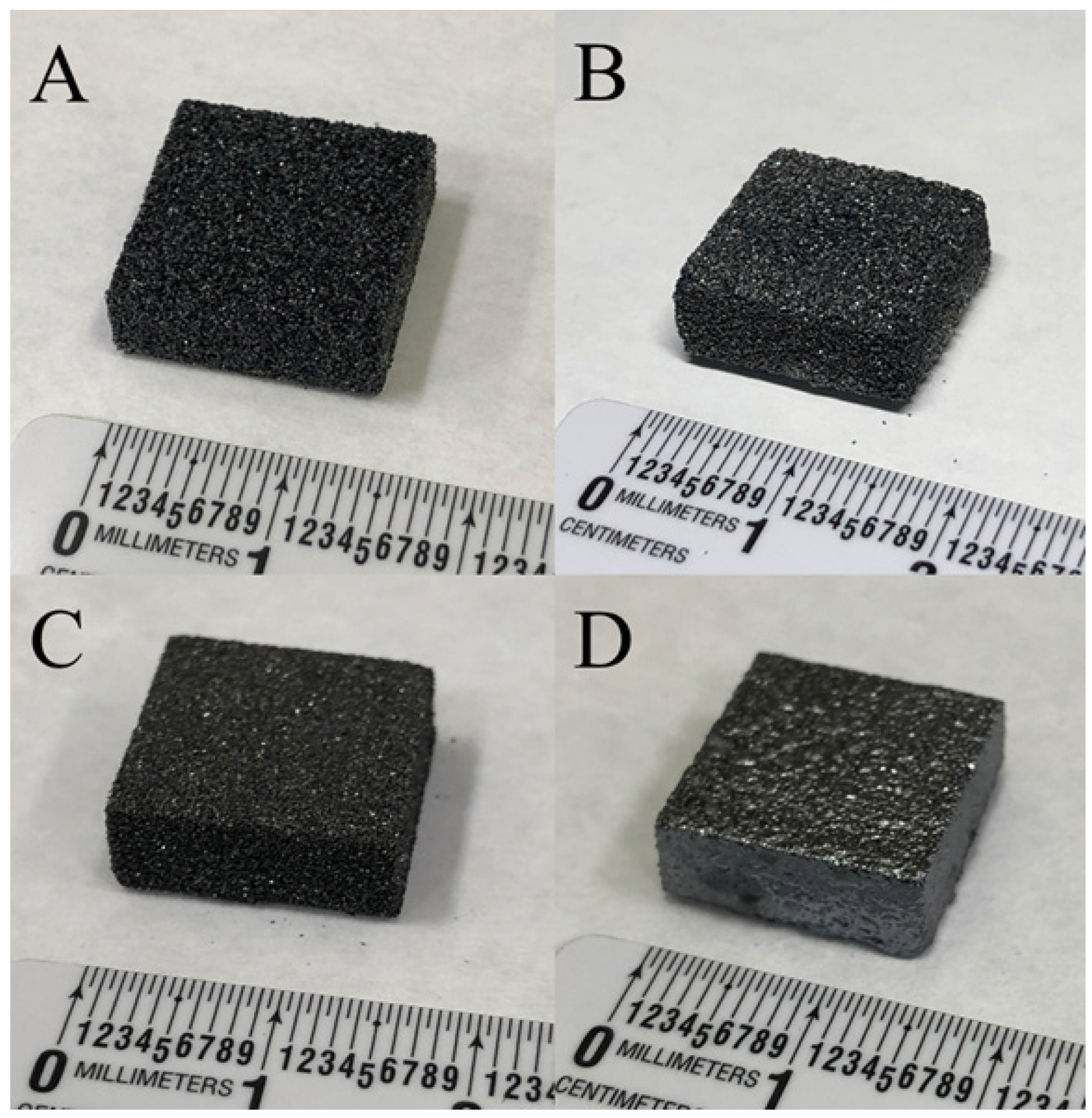
Figure 2 shows photos of the printed SiC and B4C-SiC preforms and their infiltrated composites. The SiC was printed to 48% theoretical density (TD), and the B4C-SiC preform was printed to 55%TD (see Table 2), which is relatively high for the binder jet process. This relative density difference is a consequence of the bimodal particle size distribution, where the smaller B4C particles pack into the porosity created by the larger SiC particles [36]. The shape retention is significantly different with these samples; the SiC infiltrated with Si nearly crumbles after processing, which is likely due to the debinding atmosphere cleaning the surface of carbon from the SiC particles, making the wetting of the SiC with molten Si almost impossible. As such, further studies on the SiC-Si composite were stopped. Nevertheless, the SiC-B4C blend infiltrated with Si was fully bonded and was promising speculatively because the B4C allowed more carbon retention during debinding. Further, the Si had higher wettability into these preforms, as evidenced by the macro images in Figure 2, where the Si appears to fully infiltrate the SiC-B4C-Si preform up to and including “sealing” the surface (note the shiny, lustrous appearance of the samples in Figure 2D). In contrast, Figure 2B shows a matted, dull, rough, porous particulate surface (viz., not infiltrated).
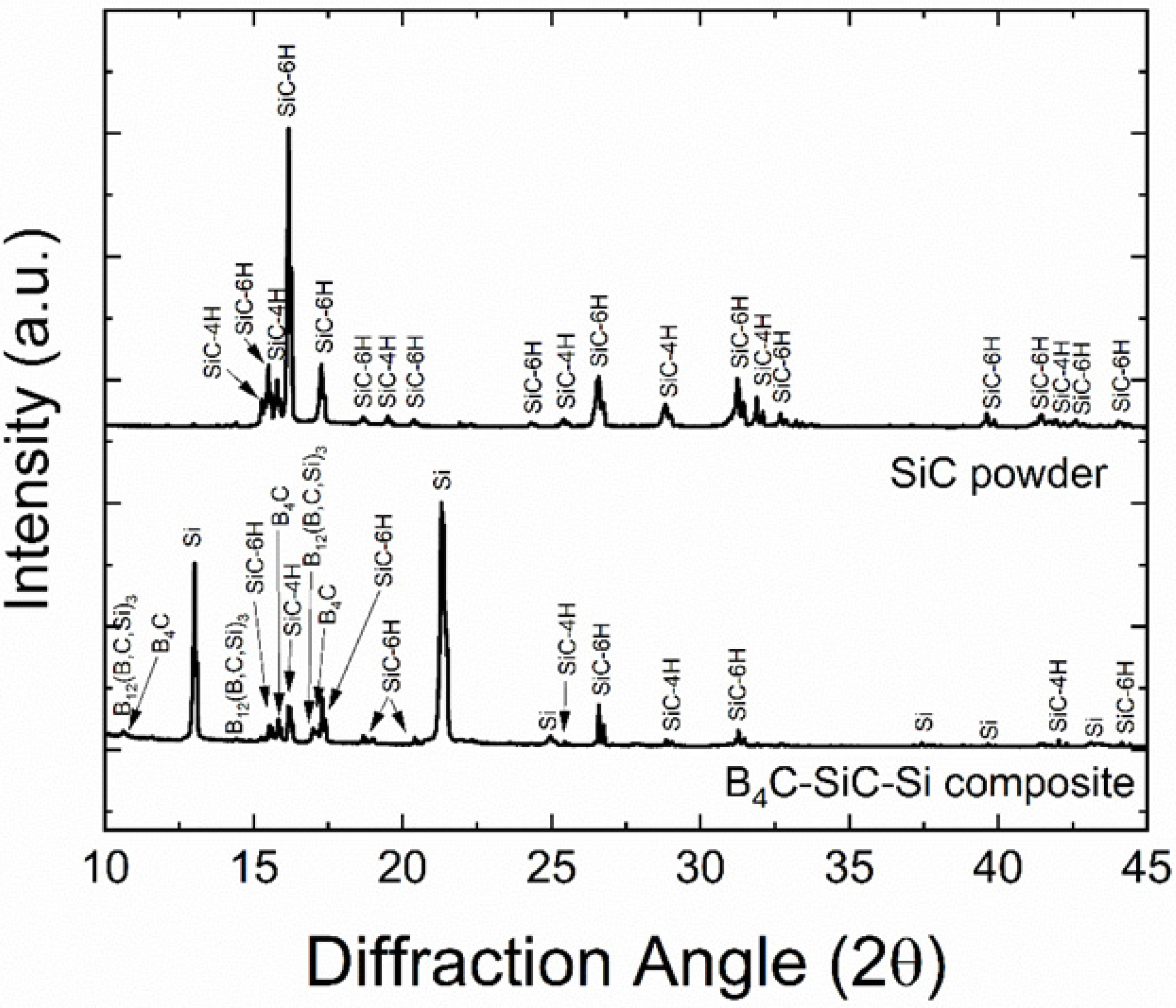
Figure 3 shows the XRD patterns of the SiC powder and the SiC-B4C-Si composite. The powder had two types of alpha-phase SiC polymorphs, 4H and 6H. The results show that the SiC powder is mostly the 6H polytype, and this can vary from different powder sources. When processing the SiC with the B4C addition and silicon melt infiltration, the amount of 4H in the composite decreased, converting to 6H during processing. The composite also consisted of B4C, a ternary phase (B12(B, C, Si)3), and residual free Si. The B4C likely reacted with Si to form this ternary phase.
Figure 4A,B show optical and SEM images, respectively, of cross-sections of the processed composite. In the optical image in Figure 4A, the black regions (pointed out with a white arrow) are pores, and the light grey regions are the ceramic particles; the white regions are Si. The density was high because there were few pores, which aligns with the measured density in Table 2. The amount of ceramic phase was measured with ImageJ as 57%, which is slightly higher than the bulk measurement above in Table 2. Moreover, it shows that the ceramic phases are dispersed well among the Si. The SEM image (backscatter mode) shows the phases of B4C, SiC, and Si. In Figure 4B, the B4C has a slightly darker shade (pointed out with an arrow), and the ternary phase recognized from XRD has a lighter shade [18,21]. This outer rim region, or reaction zone, is also seen in other reaction-bonded SiC-B4C-Si composites [21]. There is also a lighter rim (black arrow) around the SiC particles, which is possibly an edge effect or a diffusion zone of Si-B-C. There is no SiC platelet formation, and the bright white shades are Fe contamination.
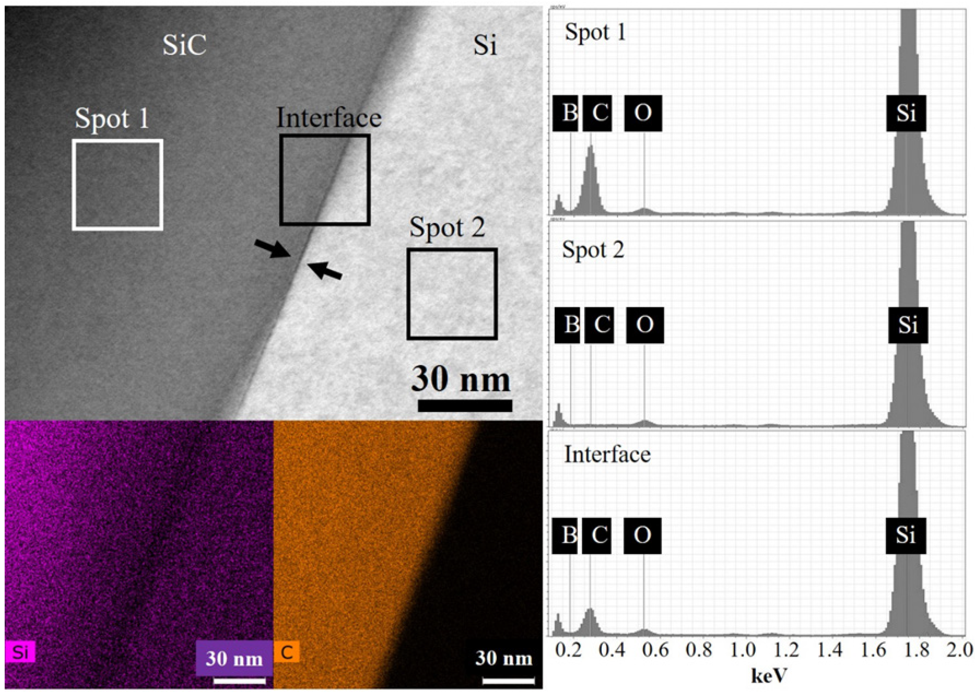
Figure 5 is a bright field (BF) scanning transmission electron microscope (STEM) image showing a section of a SiC particle and Si interface from the SiC-B4C-Si composite that was prepared by a focused ion beam (FIB) along with the EDS elemental maps and EDS elemental spectra generated from three regions indicating in the BF-STEM image. Si and carbon were separated, indicating the interface of SiC and Si. No B was detected at the interface because it was beneath the EDS detection limit. A small change in the Si level at the SiC/Si interface was detected, and the carbon content decreased abruptly across the interface from SiC into Si. The interface appeared intimate. This suggests that C from B4C plays a larger role than B in assisting the Si infiltration into SiC. Moreover, there appeared to be less Si content in the SiC toward the interface, suggesting that the edges of the SiC particles may have had impurities and sub-stoichiometry.
Figure 6 shows optical images of Vickers microhardness indentations (four-sided pyramid). Each phase of the composite was indented individually because the sizes of the indentations for the ASTM standard are not large enough to capture multiple phases at once. The indentation induced cracking in each phase. The hardness values for the matrix and two reinforcements are shown in Table 3. B4C was harder than SiC, and SiC was harder than the Si matrix material, which was expected [37]. The values of the particles were near the bulk values of the individual materials, even though there were some surface impurities or pores in the ceramic particles, as pointed out with the white arrows in Figure 6B.
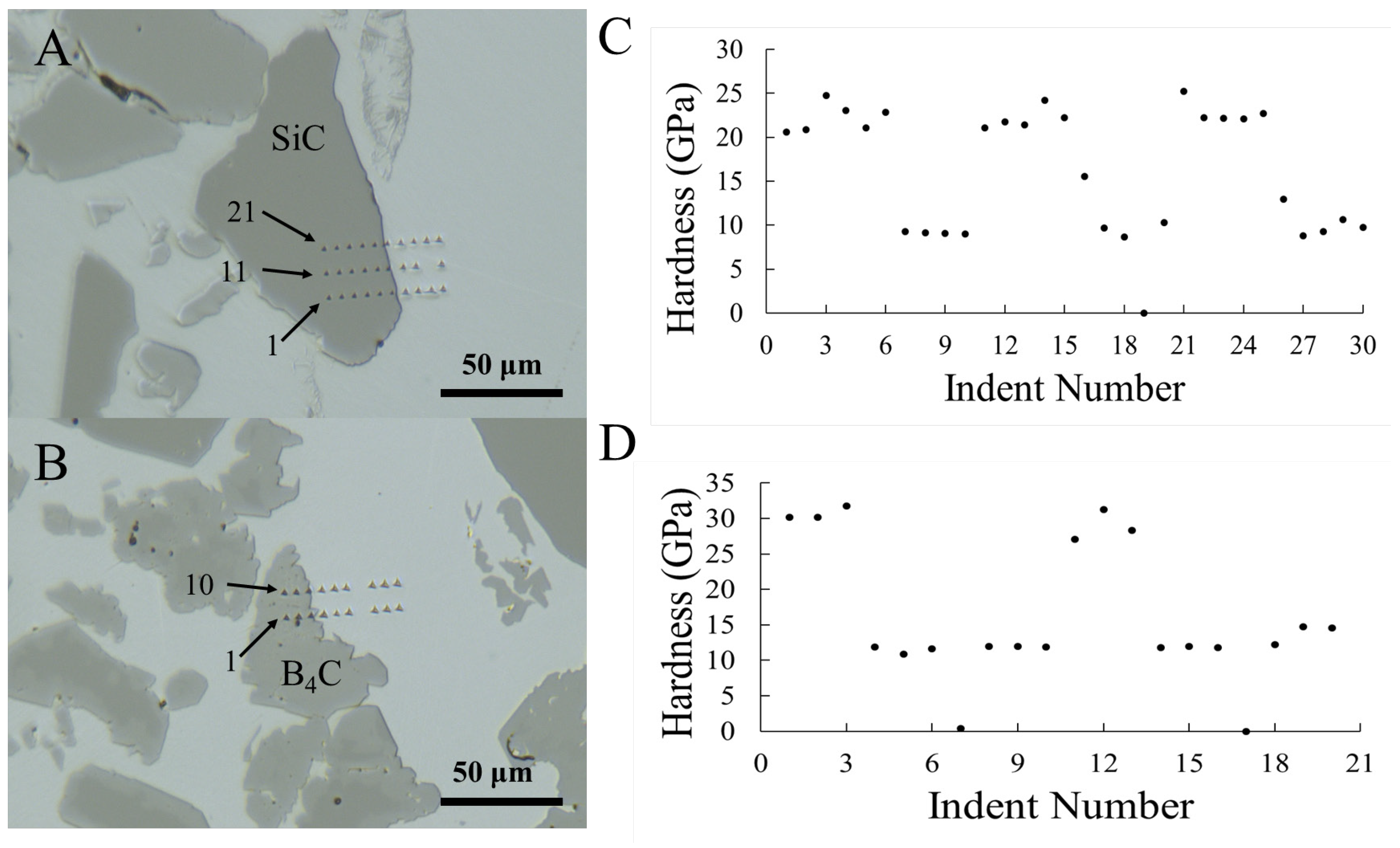
Figure 7 shows optical images of the nanoindents across the interfaces of each of the particles with the Si matrix, as well as the hardness values. In Figure 7A, the indents are numbered 1–21, and there was a distinct decrease in hardness values (Figure 7B) across the interface, except for indents 16 (~15 GPa) and 26 (~13 GPa), which encompassed some SiC and some Si. Indent 19 did not occur as there was an error in data collection. In comparison, a similar scan across the B4C-Si interface was performed. Figure 7C shows the indents across the B4C-Si interface, and Figure 7D shows the hardness values. There also is a distinct decrease in hardness across the interface, but indents that are on the interface (such as indent 12 in Figure 7C) retain the hardness value of the particle. This is different compared to indents on the interface of SiC-Si, where there is an intermediate hardness value for indents at the interface. This difference could be due to the chemical bonding behavior seen at the B4C-Si interface, compared to a more physical bond in the SiC-Si interface. The interfacial values that have an intermediate hardness value show how the composite hardness may have contributions from both materials, yielding a number between the two materials.
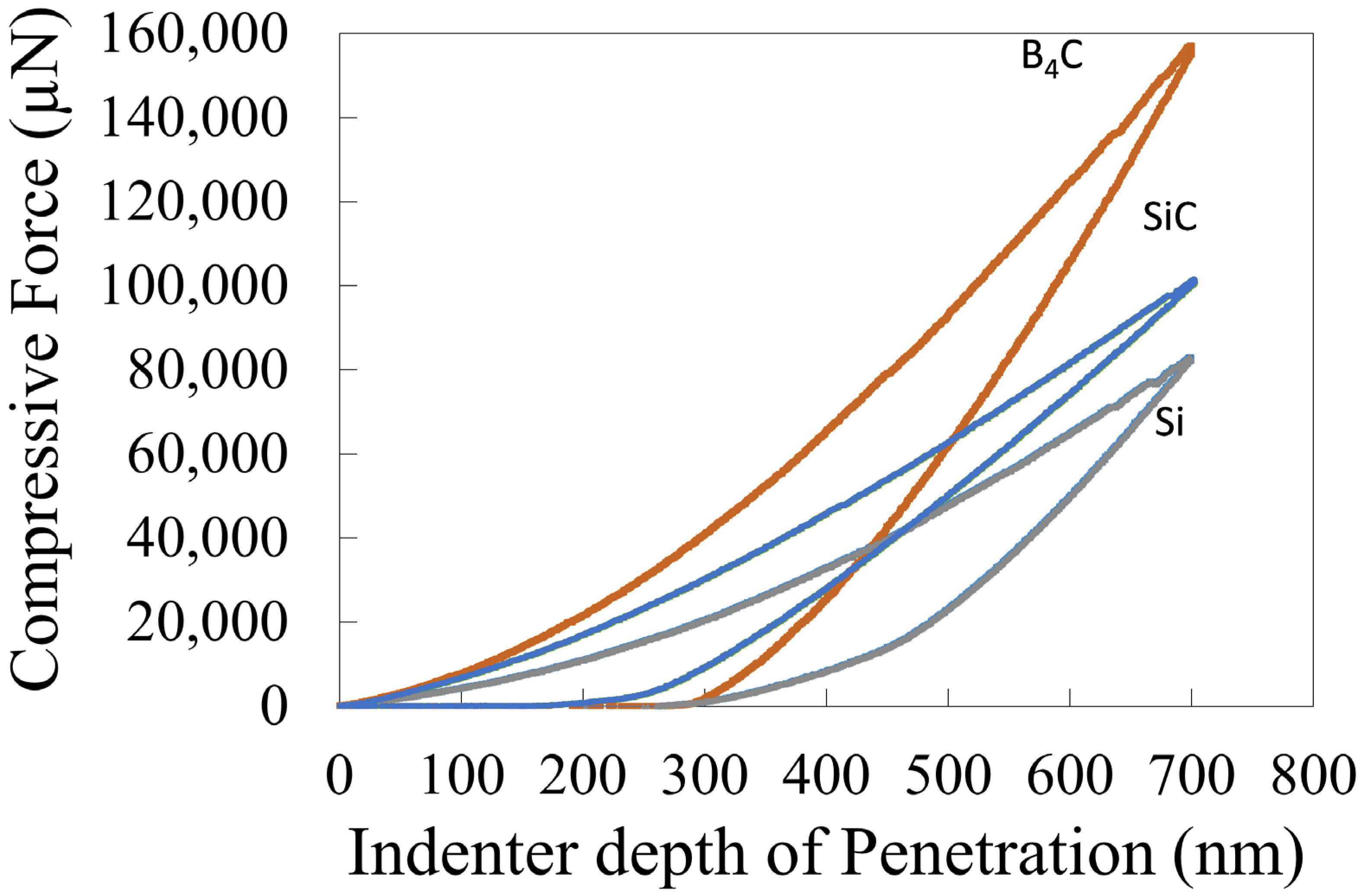
The force versus displacement of each phase was measured during nanoindentation to understand the material response. Figure 8 shows the force versus displacement data for each phase. Each phase requires a different force to experience the same amount of displacement, with B4C as the highest and Si as the lowest. Moreover, the slopes of the loading curves are different due to the stiffness differences between materials, and the hysteresis is very evident in the curves owing to the permanent plastic deformation. The force–displacement curves for each phase in Figure 8 show some pop-in behavior or discontinuities in the load, with a sudden drop in force around 600–700 nm, and this behavior is likely due to the nucleation of dislocations when the material experiences ample shear stress, as also shown in previous literature [38].
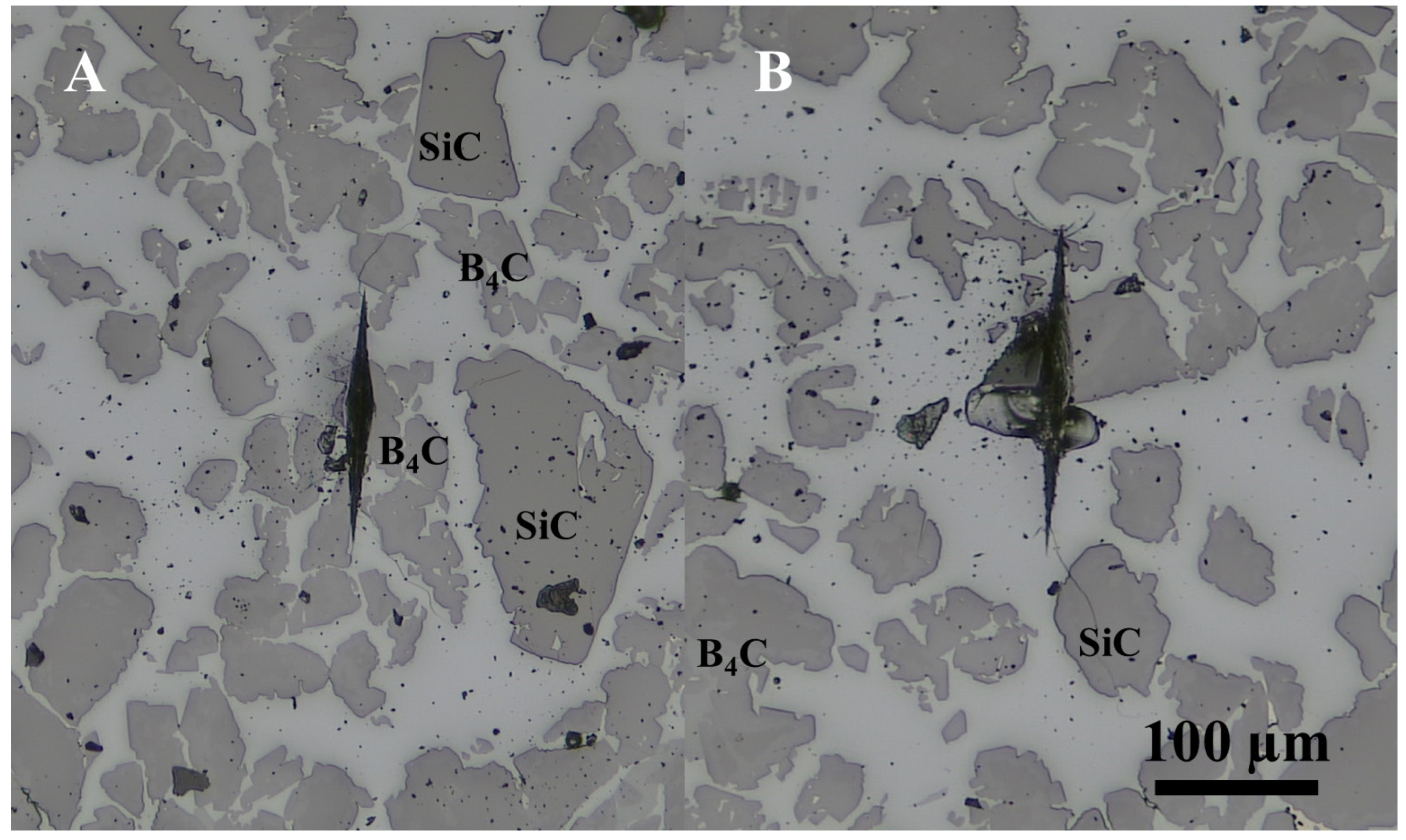
A measure of the bulk composite hardness engulfing many particles and the matrix, and the composite response is not well understood. It can be difficult to measure the hardness with large particles in a matrix material when the indenter can only indent into one small area of a particle or a small area of a small number of particles because this is not a true measure of the hardness of the bulk composites; it is more of a local value. Thus, more hardness techniques were used to understand the composite hardness with the Knoop hardness technique. It was pointed out that larger Vickers indents did not yield data that could be easily processed. The Knoop indents encompassed as much material as possible without destroying the sample, as shown in the optical image in Figure 9, and meaningful values could be extracted. The hardness values from Knoop were around 10.3 GPa, and the hardness values are compiled in Table 3. The hardness values on SiC and B4C particles were lower than the values of Vickers and nanoindentation due to the composite behavior and the encompassing of some Si in the area of the indent. Another notable observation was the reaction zone around B4C, which was still intact after the indentation in both the Knoop and Vickers hardness tests, but the images were at too low magnification to observe the indents. The nanoindents also suggested that this reaction-bonded zone provided a strong interface or chemical bond.
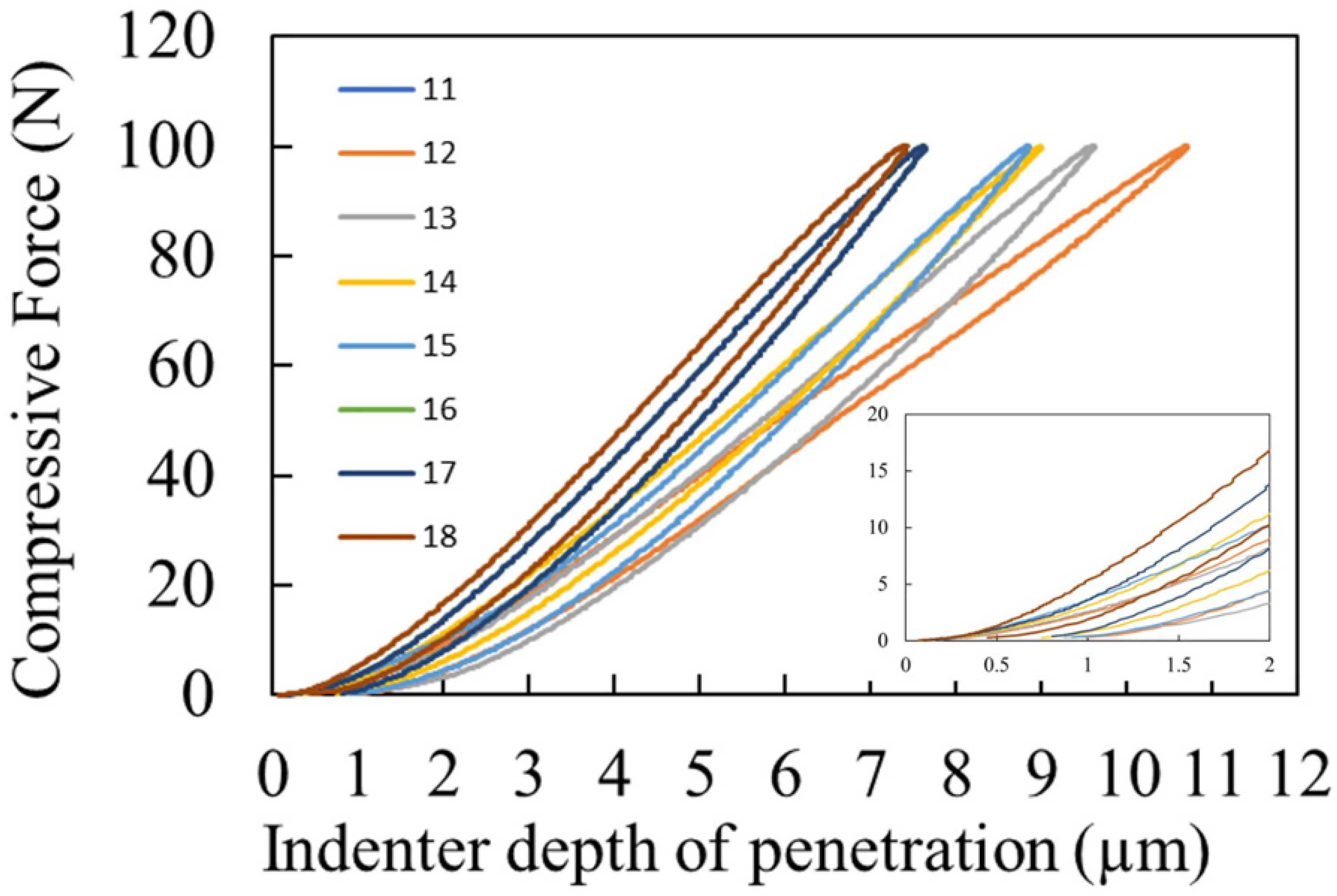
Better inclusion of all three phases is needed to understand the composite hardness and response. It has been shown that larger spherical indenters can help to achieve this [39,40]. Spherical indentation hardness was also performed to encompass more of all three phases under one indent to improve the contact area for a bulk or composite hardness value. Spherical indents were performed on the SiC-B4C-Si composite, and the data are shown in Figure 10. The curves show the behavior of the spherical indentation with load versus displacement for several indents. The behavior is similar for most of the indents, depending on how much SiC and B4C was included in the indent area. There is no pop-in as there was with the nanoindentation on all phases. These data can be used to extract more mechanical properties as in [41], but it is not done here because it is not within the scope of this work. Rather, the composite hardness values are extracted and compared to a volumetric rule of mixtures.
Figure 11 shows an image of a representative spherical indent. The spherical cracks propagate outward, and the affected area encompasses five to seven whole B4C particles and one to two SiC particles. The ring cracking is similar to that seen in SiC with a spherical indenter, allowing for hardness values to be calculated [42]. The hardness values can be calculated based on the projected area and load, as in [41,43]. The hardness values were around 18.8 GPa. Compared to a rule of mixtures composite hardness from Vickers values (20.3 GPa), the composite hardness is slightly lower than the rule of mixtures. This is most likely due to the Si matrix plasticity and the displacement of B4C and SiC particles during testing, as well as the smaller Hertzian contact and area of the indents [44]. Intuitively, this must be the case because most of these large indents encompassed more B4C particles, which would increase the bulk value. Nonetheless, the larger spherical indents encompass enough material to allow for a bulk measurement that is much closer to a value that the entire composite might experience given the rule of mixtures. This is an important finding for further correlations to other mechanical properties, such as strength, and the interfaces and bonding affect this, so the interfaces of the particles and matrix after hardness indents send a crack toward a particle are examined next.
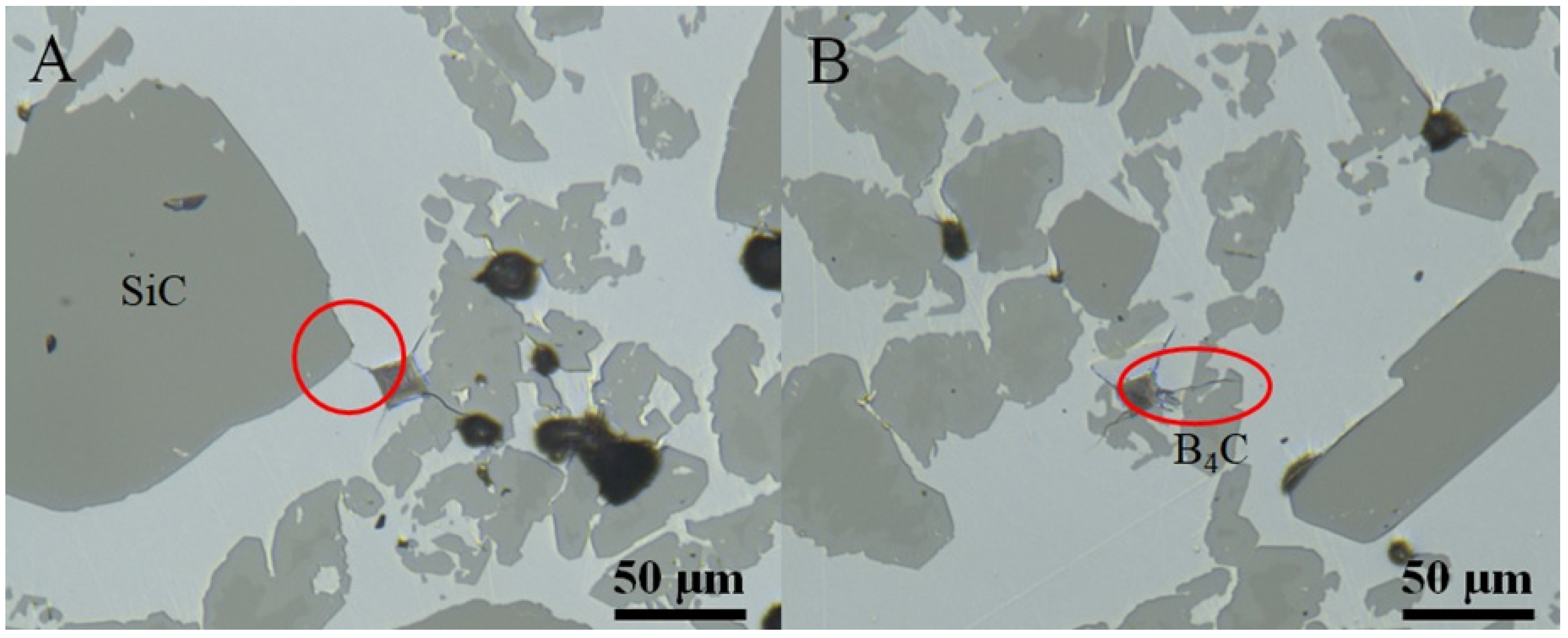
Figure 12 shows the matrix and particle interface behavior with crack propagation from Vickers microhardness indents. The indents are purposefully applied in the silicon matrix to induce cracking toward the particle interface, as in [45,46]; no hardness values are extracted from this analysis. Figure 12A shows a typical SiC-Si microstructure wherein the crack heading into the SiC particle is arrested as shown by the red circle in Figure 12A. Figure 12B shows a typical B4C-Si interface from the present research, and the cracks mostly propagate through B4C particles as shown by the red circle in Figure 12B. This shows that the interface of the SiC and Si is less intimate or more mechanical in behavior and the interface between B4C and Si is more intimate, which can be due to the formation of the ternary phase (B12(B, C, Si)3). These interfaces can affect the hardness values that have been discussed throughout this research, such as the high hardness values observed in B4C, but bulk composites with more B4C particles exhibit a slightly lower bulk value compared to the rule of mixtures. This may be due to the strong bonding, causing less plastic deformation, as shown in the varying displacement values with the same load in Figure 10. This behavior will eventually affect other mechanical properties of composites, such as the composite strength.

4. Conclusions

The addition of B4C with SiC powders was achieved via binder jet 3D printing into SiC-B4C preforms, which were subsequently melt-infiltrated with Si to form near-net-shape SiC-B4C-Si composites. The retention of carbon when B4C is added to SiC allows for successful Si infiltration. The SiC-B4C-Si composites resulted in <1% dimensional change from printed to fully infiltrated and were nearly fully dense (98.4%TD), which was only achievable with the addition of B4C particles. The composite formed a rim ternary phase on the B4C, which helped the bonding of Si to B4C particles. There was no reaction zone between SiC particles and Si, which is the critical interface for consolidating the SiC-B4C-Si composite. The composite behavior and interfaces were determined with various hardness techniques and indentation. Hardness values measured directly on single particles yielded a value near that of the bulk hardness value, giving some validity to the rule of mixtures. The spherical indention hardness values measured on a collection of particles and the matrix provided the best value, near that obtained through a rule of mixtures approach. This provides a bulk, composite value of hardness and a bulk response that can later be correlated to other mechanical properties and accurately compared to single phase ceramics. This study shows how large-particle ceramic composites can be characterized with spherical indentation hardness techniques to provide composite behavior.

5. Patents

This section is not mandatory but may be added if there are patents resulting from the work reported in this manuscript. This technology is also the technology for US Patent number US20200189145A1.

Author Contributions

Conceptualization, C.L.C.; methodology, C.L.C.; validation, C.L.C., E.C. and K.A.U.; formal analysis, TEM data generation, analysis, manuscript writing-reviewing-editing, K.A.U.; investigation, C.L.C., E.C. and K.A.U.; resources, C.L.C.; writing—original draft preparation, C.L.C., E.C. and K.A.U.; writing—review and editing, C.L.C., E.C. and K.A.U.; funding acquisition, C.L.C. All authors have read and agreed to the published version of the manuscript.

Funding

This manuscript has been authored by UT-Battelle LLC under Contract No. DE-AC05-00OR22725 with the U.S. Department of Energy. The United States Government retains, and the publisher, by accepting the article for publication, acknowledges that the United States Government retains a non-exclusive, paid-up, irrevocable, world-wide license to publish or reproduce the published form of this manuscript, or allow others to do so, for United States Government purposes. The Department of Energy will provide public access to these results of federally sponsored research in accordance with the DOE Public Access Plan (http://energy.gov/downloads/doe-public-access-plan).

Data Availability Statement

Not applicable.

Acknowledgments

The authors thank Walter Koncinski for the help with formatting and editing the manuscript, Andrew Wereszczak and Richard Berger for their help with indentation measurement and analysis, and Dorothy Coffey for assistance with TEM sample preparation. This material is based upon work supported by the U.S. Department of Energy, Office of Energy Efficiency and Renewable Energy, Office of Advanced Manufacturing and Propulsion Materials program, under the Vehicle Technology Office, under contract number DE-AC05-00OR22725.

Conflicts of Interest

The authors declare no conflict of interest.

Appendix A. Safety Considerations

SiC, B4C, and Si powders are large enough that the inhalation hazard is low. If ingested, SiC and Si can be irritants. If B4C is ingested, it can cause acute exposure to a Category 1A hazard. Please use gloves and a fume hood when handling powders.

References

  1. Popper, P.; Davies, D.G.S. The preparation and properties of self-bonded silicon carbide. Powder Metall. 1961, 4, 113–127. [Google Scholar] [CrossRef]
  2. Wang, Y.; Tan, S.; Jiang, D. The effect of porous carbon preform and the infiltration process on the properties of reaction-formed SiC. Carbon 2004, 42, 1833–1839. [Google Scholar] [CrossRef]
  3. Hozer, L.; Lee, J.-R.; Chiang, Y.-M. A Reaction-infiltrated, net-shape SiC composites. Mater. Sci. Eng. A 1995, 195, 131–143. [Google Scholar] [CrossRef]
  4. Shin, D.-W.; Park, S.S.; Choa, Y.-H.; Niihara, K. Silicon/Silicon Carbide Composites Fabricated by Infiltration of a Silicon Melt into Charcoal. J. Am. Ceram. Soc. 2004, 82, 3251–3253. [Google Scholar] [CrossRef]
  5. Presas, M.; Pastor, J.Y.; LLorca, J.; de Arellano-López, A.R.; Martínez-Fernández, J.; Sepúlveda, R.E. Mechanical behavior of biomorphic Si/SiC porous composites. Scr. Mater. 2005, 53, 1175–1180. [Google Scholar] [CrossRef]
  6. Ness, J.N.; Page, T.F. Microstructural evolution in reaction-bonded silicon carbide. J. Mater. Sci. 1986, 21, 1377–1397. [Google Scholar] [CrossRef]
  7. Sangsuwan, P.; Tewari, S.N.; Gatica, J.E.; Singh, M.; Dickerson, R. Reactive infiltration of silicon melt through microporous amorphous carbon preforms. Metall. Mater. Trans. B 1999, 30, 933–944. [Google Scholar] [CrossRef]
  8. Whalen, T.J.; Anderson, A.T. Wetting of SiC, Si3N4, and Carbon by Si and Binary Si Alloys. J. Am. Ceram. Soc. 1975, 58, 396–399. [Google Scholar] [CrossRef]
  9. Nikolopoulos, P.; Los, S.A.P.; Angelopoulos, G.N.; Naoumidis, A.; Grübmeier, H. Wettability and interfacial energies in SiC-liquid metal systems. J. Mater. Sci. 1992, 27, 139–145. [Google Scholar] [CrossRef]
  10. Molina, J.M.; Prieto, R.; Narciso, J.; Louis, E. The effect of porosity on the thermal conductivity of Al–12 wt.% Si/SiC composites. Scr. Mater. 2009, 60, 582–585. [Google Scholar] [CrossRef]
  11. Wilhelm, M.; Kornfeld, M.; Wruss, W. Development of SiC–Si composites with fine-grained SiC microstructures. J. Eur. Ceram. Soc. 1999, 19, 2155–2163. [Google Scholar] [CrossRef]
  12. Roger, J.; Guesnet, L.; Marchais, A.; Le Petitcorps, Y. SiC/Si composites elaboration by capillary infiltration of molten silicon. J. Alloys Compd. 2018, 747, 484–494. [Google Scholar] [CrossRef]
  13. McCauley, J.W.; Rim, M.P., IV. International Conference on Advanced Ceramics and Glass (2001: Wailea, Ceramic armor materials by design: Proceedings of the Ceramic Armor Materials by Design Symposium. In Proceedings of the Pac Rim IV International Conference on Advanced Ceramics and Glass, Maui, HI, USA, 4–8 November 2001; American Ceramic Society: Westerville, OH, USA, 2002. [Google Scholar]
  14. Taylor, K.; Palicka, R. Dense Carbide Composite for Armor and Abrasives. U.S. Patent 3,765,300, 16 October 1973. [Google Scholar]
  15. Panasyuk, A.D.; Oreshkin, V.D.; Maslennikova, V.R. Kinetics of the reactions of boron carbide with liquid aluminum, silicon, nickel, and iron. Sov. Powder Metall. Met. Ceram. 1979, 18, 487–490. [Google Scholar] [CrossRef]
  16. Hayun, S.; Weizmann, A.; Dariel, M.P.; Frage, N. The Effect of Particle Size Distribution on the Microstructure and the Mechanical Properties of Boron Carbide-Based Reaction-Bonded Composites. Int. J. Appl. Ceram. Technol. 2009, 6, 492–500. [Google Scholar] [CrossRef]
  17. Hayun, S.; Frage, N.; Dariel, M.P. The morphology of ceramic phases in BxC–SiC–Si infiltrated composites. J. Solid State Chem. 2006, 179, 2875–2879. [Google Scholar] [CrossRef]
  18. Hayun, S.; Weizmann, A.; Dariel, M.P.; Frage, N. Microstructural evolution during the infiltration of boron carbide with molten silicon. J. Eur. Ceram. Soc. 2010, 30, 1007–1014. [Google Scholar] [CrossRef]
  19. Mallick, D.; Kayal, T.K.; Ghosh, J.; Chakrabarti, O.P.; Biswas, S.; Maiti, H.S. Development of multi-phase B–Si–C ceramic composite by reaction sintering. Ceram. Int. 2009, 35, 1667–1669. [Google Scholar] [CrossRef]
  20. Wang, J.; Lin, W.; Jiang, Z.; Duan, L.; Yang, G. The preparation and properties of SiCw/B4C composites infiltrated with molten silicon. Ceram. Int. 2014, 40, 6793–6798. [Google Scholar] [CrossRef]
  21. Aroati, S.; Cafri, M.; Dilman, H.; Dariel, M.P.; Frage, N. Preparation of reaction bonded silicon carbide (RBSC) using boron carbide as an alternative source of carbon. J. Eur. Ceram. Soc. 2010, 31, 841–845. [Google Scholar] [CrossRef]
  22. Wong, K.V.; Hernandez, A. A Review of Additive Manufacturing. ISRN Mech. Eng. 2012, 2012, 208760. [Google Scholar] [CrossRef]
  23. Mostafaei, A.; Elliott, A.M.; Barnes, J.E.; Li, F.; Tan, W.; Cramer, C.L.; Nandwana, P.; Chmielus, M. Binder jet 3D printing—process parameters, materials, properties, and challenges. Prog. Mater. Sci. 2020, 119, 100707. [Google Scholar] [CrossRef]
  24. Moon, J.; Caballero, A.C.; Hozer, L.; Chiang, Y.-M.; Cima, M.J. Fabrication of functionally graded reaction infiltrated SiC–Si composite by three-dimensional printing (3DPTM) process. Mater. Sci. Eng. A 2001, 298, 110–119. [Google Scholar] [CrossRef]
  25. Cramer, C.L.; Elliott, A.M.; Lara-Curzio, E.; Flores-Betancourt, A.; Lance, M.J.; Han, L.; Blacker, J.; Trofimov, A.A.; Wang, H.; Cakmak, E.; et al. Properties of SiC-Si made via binder jet 3D printing of SiC powder, carbon addition, and silicon melt infiltration. J. Am. Ceram. Soc. 2021, 101, 5467–5478. [Google Scholar] [CrossRef]
  26. Fleisher, A.; Zolotaryov, D.; Kovalevsky, A.; Muller-Kamskii, G.; Eshed, E.; Kazakin, M.; Popov, V.V., Jr. Reaction bonding of silicon carbides by Binder Jet 3D-Printing, phenolic resin binder impregnation and capillary liquid silicon infiltration. Ceram. Int. 2019, 45, 18023–18029. [Google Scholar] [CrossRef]
  27. Oh, J.W.; Park, J.; Nahm, S.; Choi, H. SiC-Si composite part fabrication via SiC powder binder jetting additive manufacturing and molten-Si infiltration. Int. J. Refract. Met. Hard Mater. 2021, 101, 105686. [Google Scholar] [CrossRef]
  28. Hansen, N. Hall–Petch relation and boundary strengthening. Scr. Mater. 2004, 51, 801–806. [Google Scholar] [CrossRef]
  29. Ryou, H.; Drazin, J.W.; Wahl, K.J.; Qadri, S.B.; Gorzkowski, E.P.; Feigelson, B.N.; Wollmershauser, J.A. Below the Hall-Petch Limit in Nanocrystalline Ceramics. ACS Nano 2018, 12, 3083–3094. [Google Scholar] [CrossRef]
  30. Chavoshi, S.Z.; Branicio, P.S.; An, Q. Transition between Hall-Petch and inverse Hall-Petch behavior in nanocrystalline silicon carbide. Phys. Rev. Mater. 2021, 5, 073606. [Google Scholar] [CrossRef]
  31. Holmquist, T.J.; Wereszczak, A.A. Using Hertzian Indentation to Understand the Strength and Ballistic Resistance of Silicon Carbide. Int. J. Appl. Ceram. Technol. 2010, 7, 625–634. [Google Scholar] [CrossRef]
  32. Hackett, B.L.; Wereszczak, A.A.; Pharr, G.M. Evaluation of new technique to estimate yield stress in brittle materials via spherical indentation testing. In Proceedings of the 42nd International Conference on Advanced Ceramics and Composites: Ceramic Engineering and Science, Daytona Beach, FL, USA, 21–26 January 2018; pp. 61–71. [Google Scholar]
  33. Cramer, C.L.; Nandwana, P.; Lowden, R.A.; Elliott, A.M. Infiltration studies of additive manufacture of WC with Co using binder jetting and pressureless melt method. Addit. Manuf. 2019, 28, 333–343. [Google Scholar] [CrossRef]
  34. Nandwana, P.; Elliott, A.M.; Siddel, D.; Merriman, A.; Peter, W.H.; Babu, S.S. Powder bed binder jet 3D printing of Inconel 718: Densification, microstructural evolution and challenges☆. Curr. Opin. Solid State Mater. Sci. 2017, 21, 207–218. [Google Scholar] [CrossRef]
  35. Bai, Y.; Williams, C.B. The effect of inkjetted nanoparticles on metal part properties in binder jetting additive manufacturing. Nanotechnology 2018, 29, 395706. [Google Scholar] [CrossRef] [PubMed]
  36. Bai, Y.; Wagner, G.; Williams, C.B. Effect of Bimodal Powder Mixture on Powder Packing Density and Sintered Density in Binder Jetting of Metals. In International Solid Freeform Fabrication Symposium; University of Texas: Austin, TX, USA, 2015. [Google Scholar]
  37. Fitzgerald, A.M.; Dauskardt, R.H.; Kenny, T.W. Fracture toughness and crack growth phenomena of plasma-etched single crystal silicon. Sens. Actuators A Phys. 2000, 83, 194–199. [Google Scholar] [CrossRef]
  38. Dub, S.N.; Kushch, V.I.; Kaidash, O.N.; Sereda, V.P.; Panasyuk, T.S. Initiation of a plastic flow in boron carbide at nanoindentation. J. Superhard Mater. 2015, 37, 8–13. [Google Scholar] [CrossRef]
  39. Ekici, R.; Apalak, M.K.; Yıldırım, M.; Nair, F. Effects of random particle dispersion and size on the indentation behavior of SiC particle reinforced metal matrix composites. Mater. Des. 2010, 31, 2818–2833. [Google Scholar] [CrossRef]
  40. Pereyra, R.; Shen, Y.L. Characterization of particle concentration in indentation-deformed metal-ceramic composites. Mater. Charact. 2004, 53, 373–380. [Google Scholar] [CrossRef]
  41. Wereszczak, A.A.; Morrissey, T.G.; Ferber, M.K.; Bortle, K.P.; Rodgers, E.A.; Tsoi, G.; Montgomery, J.M.; Vohra, Y.; Toller, S. Responses of siliceous materials to high pressure. Adv. Ceram. Armor IX 2013, 1–13. [Google Scholar]
  42. Wereszczak, A.A.; Johanns, K.E.; Jadaan, O.M. Hertzian ring crack initiation in hot-pressed silicon carbides. J. Am. Ceram. Soc. 2009, 92, 1788–1795. [Google Scholar] [CrossRef]
  43. Erhard, R. Martens Hardness-More than just hardness testing. VDI BERICHTE 2002, 1685, 385–392. [Google Scholar]
  44. Jadaan, O.M.; Wereszczak, A.A.; Johanns, K.E.; Daloz, W.L. Weibull effective area for Hertzian ring crack initiation. Int. J. Appl. Ceram. Technol. 2011, 8, 824–831. [Google Scholar] [CrossRef]
  45. Demir, A. Effect of Nicalon SiC fibre heat treatment on short fibre reinforced β-sialon ceramics. J. Eur. Ceram. Soc. 2012, 32, 1405–1411. [Google Scholar] [CrossRef]
  46. Frazer, D.; Abad, M.D.; Krumwiede, D.; Back, C.A.; Khalifa, H.E.; Deck, C.P.; Hosemann, P. Localized mechanical property assessment of SiC/SiC composite materials. Compos. Part A Appl. Sci. Manuf. 2015, 70, 93–101. [Google Scholar] [CrossRef]
Figure 1. A schematic of the infiltration setup for printed preforms.
Jcs 07 00172 g001
Figure 2. Macro images of (A) as-printed SiC preform, (B) a SiC preform infiltrated with Si, (C) a SiC-B4C preform, and (D) a SiC-B4C preform infiltrated with Si.
Jcs 07 00172 g002
Figure 3. XRD patterns of the SiC powder and SiC-B4C-Si composite.
Jcs 07 00172 g003
Figure 4. Cross-sections of the SiC-B4C-Si composite showing (A) an optical view and (B) and backscatter SEM mode view. In (A), the black regions are pores in the samples (arrow); the lighter shades of grey are the solid phases.
Jcs 07 00172 g004
Figure 5. BF-STEM image of SiC particle and Si interface from the SiC-B4C-Si composite with corresponding EDS spectra acquired from the indicated locations in the BF-STEM image and EDS elemental maps for Si and C.
Jcs 07 00172 g005
Figure 6. Optical image of the SiC-B4C-Si composite sample showing examples of Vickers microhardness indentations on composite samples performed on a preform infiltrated with only Si in (A) the Si matrix, (B) within a SiC particle, and (C) within a B4C particle.
Jcs 07 00172 g006
Figure 7. Optical image of (A) the SiC-Si interface and (B) the B4C-Si interface revealing nanoindentation across particle–matrix interfaces: (A) indents across the SiC-Si interface with (C) corresponding indent hardness values, (B) indents across the B4C-Si interface with (D) corresponding indent hardness values of the B4C-Si interface.
Jcs 07 00172 g007
Figure 8. Berkovich indenter force versus displacement curve for each phase taken at the maximum depth of roughly 700 nm.
Jcs 07 00172 g008
Figure 9. Optical images of Knoop indents on the SiC-B4C-Si composite showing (A) a mostly clean indent on the B4C and (B) an indent on the side of a SiC particle that experienced more deformation in the Si matrix.
Jcs 07 00172 g009
Figure 10. Indentation curves of compressive force versus indenter depth generated with the Zwick indentation system for the SiC-B4C-Si composites.
Jcs 07 00172 g010
Figure 11. Optical image of a spherical indent on the composite showing more area of contact to encompass more of the response of all three phases.
Jcs 07 00172 g011
Figure 12. Optical image of the SiC-B4C-Si composite showing matrix and particle interface behavior through crack propagation from Vickers microhardness indents.
Jcs 07 00172 g012
Table 1. Chemical analysis of samples showing the wt.% of elements of powder before printing and after printing and debinding.
ElementSiC PowderPrinted and Debinded SiCB4C-SiC Powder BlendPrinted and Debinded B4C-SiC
Si69.3 ± 1.471.1 ± 1.429.4 ± 0.628.7 ± 0.6
C29.6 ± 0.629.0 ± 0.624.9 ± 0.526.3 ± 0.5
B----45.7 ± 0.945.0 ± 0.9
Table 2. Dimensions and densities of the preforms and composites.
Printed SiC PreformPrinted SiC-B4C PreformInfiltrated SiC-Si CompositeInfiltrated B4C-SiC-Si Composite
Dimensions (mm)15.2 × 15.1 × 5.115.1 × 15.1 × 5.115.2 × 15.1 × 5.115.2 × 14.9 × 5.1
Density (g/cm3, %TD)1.57, 481.54, 55n/a2.5, 98.4
Table 3. Hardness values of matrix and reinforcement performed with Vickers hardness indentation, nanoindentation, Knoop indentation, and spherical indentation.
Phase
B4C ParticlesSiC ParticlesSi Matrix
Vickers hardness on phases (GPa)31.8 ± 0.426.5 ± 0.59.2 ± 0.3
Nanohardness on phases (GPa)29.8 ± 1.322.3 ± 1.89.3 ± 0.7
Knoop hardness (GPa)10.3 ± 2.0
Rockwell C (Spherical) hardness on composite (GPa)18.8 ± 2.2
Calculated composite hardness by rule of mixtures with Vickers values20.3
Disclaimer/Publisher’s Note: The statements, opinions and data contained in all publications are solely those of the individual author(s) and contributor(s) and not of MDPI and/or the editor(s). MDPI and/or the editor(s) disclaim responsibility for any injury to people or property resulting from any ideas, methods, instructions or products referred to in the content.