Abstract
The results of the comprehensive magnetoelectric interaction research in three-layer structure Ni–piezoceramic BaTiO3–Ni are presented. It has been theoretically shown and experimentally confirmed that, in the general case, the dependence of the magnetoelectric response has non-linear character. At low bias magnetic field, a quadratic dependence magnetoelectric response from an AC magnetic field is observed then there is a linear section, as well as at high values of the field magnetoelectric response has saturation. The obtained values of the magnetoelectric characteristics (αEmax = 32 V(cmOe) for resonance and 437 mV/(cmOe) for field dependence) for lead-free three-layer structure barium–titanate–piezoceramic nickel are comparable with the magnetoelectric characteristics for similar structures, based on lead-containing ceramics.
1. Introduction
Magnetostrictive–piezoelectric composites have unique properties due to mechanical interaction between magnetic and piezoelectric phases. This interaction leads to intercorrelation of magnetic and electrical characteristics of such structures. The magnetoelectric (ME) effect, which consists in the appearance of polarization in a magnetic field or, conversely, in a change in magnetization in an electric field, is one of the effects of such a correlation. The discovery of the ME effect in composites opens up wide opportunities for creating fundamentally new electronic devices that cannot be created using traditional materials [1,2,3,4,5]. Previously, various types of composites were studied, consisting of various ferromagnetic and ferroelectric phases in the form of bulk composites [6,7], bilayer, or three-layer structures [8,9,10,11,12], as well as nanocomposites in the form of nanopillars in the main matrix, core–shell particles, and core–shell nanofibers [13,14]. Currently, some of the most-used piezoelectrics in the manufacture of composite materials are piezoceramics based on lead–zirconate–titanate (PZT). ME structures using such materials have high dielectric, piezoelectric, and ME characteristics. However, the environmental orientation of modern technologies, the high toxicity of lead, and its ability to accumulate in the human body imposes requirements for the rejection of lead-containing materials. The aim of this work was to study the ME effect in symmetrical three-layer structures consisting of lead-free piezoceramics based on barium titanate and polycrystalline nickel.
2. Materials and Methods
The object of study in this work was three-layer symmetric structures Ni–piezoceramic BaTiO3–Ni. The choice of a symmetric structure is due to the fact that, in an asymmetric ME structure, along with longitudinal vibrations, bending vibrations also arise, which lead to a weakening of the response [15]. The samples had the shape of a disk with a diameter of D = 9 mm. The thicknesses of the piezoceramic based on barium titanate and one nickel plate were tp = 0.5 mm and tm1 = 0.25 mm, respectively. Plates of ceramic and metal were connected with epoxy adhesive with a thickness tg of less than 0.01 mm. As a piezoelectric material, we used a piezoceramic fabricated on the basis of barium titanate doped with nickel ferrite in an amount of 0.1 wt%. This made it possible to reduce the sintering temperature to 1300 °C and to obtain ceramics with good characteristics: density was 5.5 g/cm3, relative permittivity ε33 = 1450, resistivity was 1.0 × 10¹⁰ Ω m, and piezoelectric moduli were d31 = 68 pC/N and d33 =156 pC/N. The manufacturing technology of piezoceramics contained a number of operations, namely, the production of barium titanate, the production of nickel ferrite, and the doping of barium titanate with ferrite. Barium titanate was obtained by conventional ceramic technology using barium carbonate BaCO3 and titanium oxide TiO2 sort pure for analysis. The composition of the mixture was calculated, taking into account the content of the main substance. The initial components were weighed on an analytical balance VLR-200. Their mixing and grinding was carried out in a ball mill in the presence of a liquid medium (ethyl alcohol) for 30 min. The resulting mass was pressed into briquettes under a pressure of 5 × 10⁷ Pa. The synthesis was carried out in air at a temperature of 1200 °C for two hours. Crushing and grinding of the resulting material was carried out in a jasper mortar, followed by sifting through a sieve with a mesh size of 7 microns. Nickel ferrite was obtained by a similar technology from iron oxides Fe2O3 and nickel NiO sort pure for analysis. The difference was that its synthesis was carried out in air for two hours at a temperature of 1100 °C. The technology for obtaining doped barium titanate included weighing the initial components in the amount of 99.9 wt.% barium titanate, 0.1 wt.% nickel ferrite. Their mixing was carried out in a jasper mortar in a liquid medium (ethyl alcohol) for an hour. The resulting mixture was pressed into briquettes under a pressure of 2 × 10⁸ Pa using an aqueous solution of polyvinyl alcohol as a plasticizer. The blanks were sintered in air at a temperature of 1300 °C for two hours. The furnace cooling rate did not exceed 50 degrees per hour. The resulting ceramic blanks were subjected to plane-parallel grinding. The electrodes were applied by burning silver paste at a temperature of 750 °C for 30 min. The samples were polarized at a temperature of 100 °C for an hour in an electric field of 1000 V/mm, followed by cooling in this field to room temperature for half an hour. Barium titanate was polarized at a temperature of 100 °C for one hour in an electric field of 1000 V/mm, followed by cooling in this field to room temperature for half an hour. Polycrystalline nickel was used as a magnetostrictive material. Figure 1 shows a photograph of the sample and a fragment of a cross-section of a layered structure.
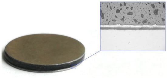
Figure 1.
Sample foto and the fragment of the cross-section of the layered nickel–piezoceramic structure based on barium titanate.
The nickel plate has a light color, and the barium titanate piezoceramic plate has a dark color. Pores are clearly visible on ceramics. The interface has a straight line, consisting of two parts. A silver electrode is directly adjacent to the ceramic. Its thickness is about 5 µm, and the polymer layer of epoxy adhesive is about 8 µm thick. The total thickness of the layer between ceramic and nickel does not exceed 13 µm, which makes it possible to achieve a high degree of interaction between the piezoelectric and magnetostrictive phases.
To study the linear ME effect, we measured the voltage that appears on the sample under the action of alternating and magnetizing magnetic fields. The ME signal generated by the sample was fed to a preamplifier that served to match the impedance and amplify the signal. An oscilloscope was used to register it. During measurements, alternating and biasing fields were applied along the plane of the sample perpendicular to the direction of polarization (transverse ME effect). In the case of the low-frequency effect, the strength of the AC magnetic field Hac, generated by the Helmholtz coils, was 1 Oe. The measurements were carried out at a frequency of 1 kHz. When studying the ME effect in the region of electromechanical resonance, the intensity of the AC magnetic field was 0.01 Oe. The ME coefficient αE was determined as the ratio of the measured voltage V to the intensity of the AC magnetic field and the thickness of the piezoelectric material, i.e., αE = V/(Hac tp). The field dependence of the ME effect was obtained by recording the ME signal, depending on the magnitude of the bias field in the field range from 0 to 1000 Oe.
The nonlinear ME effect was studied by measuring the voltage that appears on the sample when an AC magnetic field (0–1000 Oe) with a frequency of 50 Hz is applied to it. This made it possible to determine the maximum value of the electric field Emax generated in the sample and the magnitude of the quadratic ME effect observed in the initial part of the dependence and the region of maximum signal change. These characteristics are of interest when designing sensors operating in alternating and pulse magnetic fields.
3. Theoretical Description of the ME Effect
As a model, we consider a three-layer cylindrical structure, consisting of a piezoelectric layer with a thickness of tp and two magnetostrictive layers with a thickness of tm1 each, located symmetrically with respect to the piezoelectric layer. A schematic representation of the structure is shown in Figure 2.
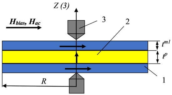
Figure 2.
Schematic diagram of the structure. 1—nickel layer, 2—piezoceramic based on barium titanate, and 3—electrodes.
The theoretical description is based on the join solution of the system equations of the theory of elasticity (generalized Hooke’s law) and the equation of electrostatics in the following form:
where the indices i and j take the values 1 and 2, with i ≠ j. Here, , , and are the components of strain and stress tensors for the piezoelectric and magnetostrictive phases, is the component of the electric induction vector, and and are the components of the vector electric and magnetic field in a piezoelectric and a magnet, respectively. is the piezoelectric modulus, is magnetostriction, , is the relative permittivity of the piezoelectric, is the dielectric constant, and и and are the Young’s moduli of the piezoelectric and magnetostrictive phases.
We were using the equation of motion of the medium under the assumption that the displacements of the piezoelectric and magnetostrictive media are the same. Under this assumption, the equation of motion has following form:
Here, is the average density of the sample, are the average values of stress tensor components, is the thickness of two magnetostrictive layers, tm1 is the thickness of one magnetostrictive layer, and tp is the thickness of the piezoelectric layer.
Since the samples are disk-shaped, it is convenient to use a cylindrical coordinate system for further calculations. Expressing, from Equations (1) and (2), the components of the stress tensor in terms of the components of the strain tensor and substituting them into Equations (3) and (4) in a cylindrical coordinate system, we obtain the following equations:
Here , are the strain tensor components in the cylindrical coordinate system, is the magnetostriction of nickel, and ω is the angular frequency of oscillations.
Performing calculations similar to the calculations in [16], for the electric field induced in the piezoelectric, we obtain the expression in the form:
Here, we introduced the notation J1(κ) is the Bessel function of the first kind, κ = kR is dimensionless parameter, is wave number, , , and is the square of the electromechanical coupling coefficient for planar oscillations.
Equation (11) makes it possible to calculate the magnitude of the induced electric field using the physical parameters of the materials and the geometric dimensions of the structure.
4. Results and Discussion
As follows from expression (11), the electric field induced in the piezoelectric is proportional to the magnitude of the magnetostriction of the magnet, which, in the general case, is a nonlinear function of the magnetic field. At the experimental study of the ME effect is carried out, as a rule, by recording a signal when the sample is placed in AC magnetic field Hac and a bias field Hbias, i.e., H = Hbias + Hac, where Hac ≪ Hbias. In this case, the magnetostriction can be expanded into a series in terms of the magnitude of the AC magnetic field and, limiting ourselves to the linear term of the expansion, we obtain an expression for the electric field strength in the form:
where is the so-called piezomagnetic coefficient. Hence, for the previously introduced linear ME voltage coefficient, we obtain the expression in the form:
As follows from expression (13), the linear ME voltage coefficient depends both on the frequency of the AC magnetic field, through the dependence of the dimensionless parameter κ on frequency, and on the magnitude of the bias field q(Hbias). The frequency dependence has a resonant character and, as was first predicted in [17], when the value of Δa = 0, a peak increase in the effect is observed. Figure 3 shows the frequency dependence of the linear ME voltage coefficient. The measurements were carried out at the magnitude of the bias field Hbias = 240 Oe, corresponding to the maximum ME signal.
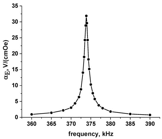
Figure 3.
Frequency dependence of the linear ME voltage coefficient.
As can see from Figure 3, in full accordance with the theory, a resonant increase in the effect is observed, and the maximum value of the ME voltage coefficient reaches the value αE,max = 32 V/(cm Oe), which is comparable to the value for similar structures with lead-containing ceramics Ni/PZT/Ni, for which, according to [18], the value αE,max = 90 V/(cm Oe) was obtained.
The dependence of the linear ME coefficient αE on the magnitude of the bias field Hbias is called the field dependence. Figure 4 shows the field dependence of the low-frequency ME coefficient. The measurements were carried out at a frequency f = 1 kHz with AC magnetic field Hac = 1 Oe.
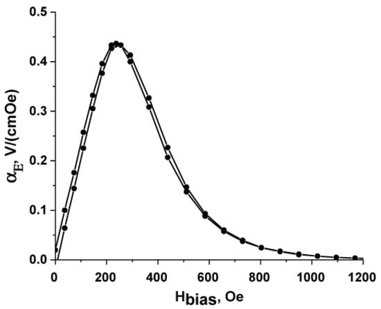
Figure 4.
Field dependence of the linear ME coefficient.
From Figure 4, it follows that the value of the low-frequency ME coefficient in the region of low magnetic fields (H < 100 Oe) increases linearly, reaches a maximum of 437 mV/(cm Oe) in a field Hbias = 240 Oe, and then decreases monotonically to zero in fields above 1000 Oe. Due to the residual magnetization, hysteresis is observed with a coercive force equal to 8 Oe. For comparison, on heterostructures with lead-containing Ni/PZT/Ni piezoceramics at similar sizes, the maximum value of the low-frequency ME coefficient reached αE = 480 mV/(cm Oe) [18].
Figure 5 shows the dependence of the voltage generated by the structure in a bias field Hm = 240 Oe on the magnitude of the alternating magnetic field. It can be seen that, at magnetic field amplitudes up to 20 Oe, a linear dependence is observed. At large values of the amplitude, there is a deviation from the linear dependence and the signal decreases. The result obtained is explained by the existence of a smeared maximum on the field dependence of the ME coefficient (Figure 4). The high sensitivity of the ME signal and its linear dependence is of interest for creating sensors for alternating magnetic fields on their basis.
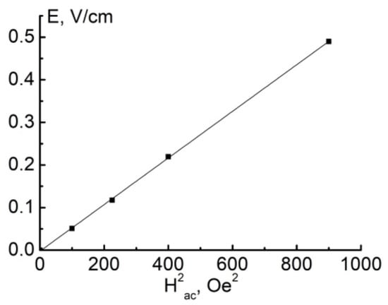
Figure 5.
Dependence of the generated voltage on the amplitude of the alternating magnetic field in a constant field of 240 Oe.
Expression (13) shows that the linear ME coefficient αE is directly proportional to the piezomagnetic coefficient q, which is the derivative of magnetostriction with respect to the magnetic field at a certain value of the bias field Hbias, therefore, as shown in [19], the field dependence of the ME coefficient can be used to restore the dependence of magnetostriction on the magnitude of the magnetic field, i.e.,
As follows from expression (10), this dependence will be the dependence of the electric field induced in the piezoelectric on the intensity of the AC magnetic field in the absence of a bias field. Figure 5 shows the experimental dependence of the nonlinear ME effect at a frequency f = 50 Hz, and, in Figure 6, the dependence of nickel magnetostriction is obtained from the field dependence of the ME coefficient using expression (14).
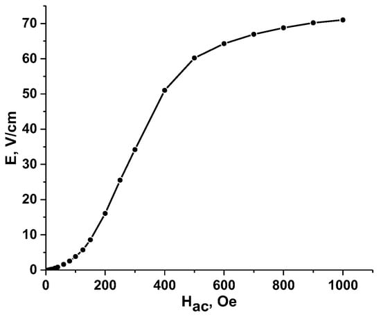
Figure 6.
Dependence of the induced electric field on AC magnetic field at Hbias = 0.
As can be seen from Figure 6 and Figure 7, the dependence of the induced electric field completely coincides with the dependence of magnetostriction, which confirms the validity of expression (11). This also indicates that the basis of all ME effects occurring in ME composite materials is the same mechanism–mechanical interaction between the piezoelectric and magnetostrictive phases. The maximum electric field generated in the sample in the signal saturation mode was 70 V/cm. The magnitude of the magnetic field at which the maximum sensitivity of the nonlinear ME coefficient is observed is approximately 250 Oe. A detailed study of the nonlinear ME effect showed that, in the initial part of the curve, the dependence has a quadratic character, i.e., can be written as , where , is the coefficient characterizing the quadratic ME effect. In contrast to the linear ME effect, the quadratic ME effect is observed at twice the frequency of the AC magnetic field, as a result of which the resonant increase in the signal occurs at a frequency that is half the frequency of the main resonance for the linear ME effect [20,21,22]. Figure 8 shows the dependence of the magnitude of the induced electric field on the square of the AC magnetic field in the region of magnetic fields (0–30) Oe.
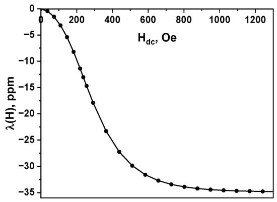
Figure 7.
Nickel magnetostriction calculated from the field dependence ME effect.
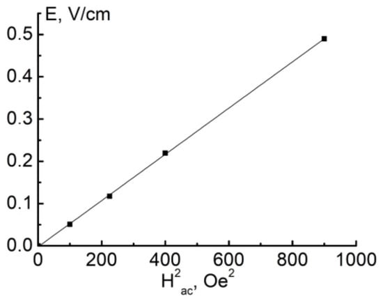
Figure 8.
Dependence of the induced electric field on the square AC magnetic field at low fields.
Figure 8 shows that the magnitude of the ME signal is proportional to the square of the applied ac magnetic field in the region of low fields. The evaluation showed that the value of the quadratic ME coefficient was 5.4 × 10⁻⁴ V/(cm Oe2). The quadratic dependence of the electric field on the magnetic field in the initial section is due to the fact that its mechanism of occurrence is based on a change in magnetization due to elastic displacements of domain walls.
It should be noted that there are qualitative differences between the linear and nonlinear ME effects. In the case of the nonlinear ME effect, in contrast to the linear one, the frequency is doubled, and the signal shape depends on the amplitude of the alternating magnetic field. Figure 9 shows the shape of the output ME signals obtained under the action of an alternating magnetic field with an amplitude of 50 Oe (curve 2), 250 Oe (curve 3), and 800 Oe (curve 4). The results are given in comparison with the reference signal (curve 1) characterizing the magnetic field. In the initial section of the dependence curve of the electric field strength generated in the sample on the magnetic one (Figure 6), the signal has a sinusoidal shape, which, as the amplitude of the alternating magnetic field increases, becomes trapezoidal. These results are explained by the behavior of nickel ferrite magnetostriction. Its sign does not depend on the direction of the magnetic field. The consequence is a doubling of the frequency of the ME signal. The change in its shape is explained by the dependence of the nickel magnetostriction on the magnetic field, the value of which saturates with an increase in the magnetic field and thereby limits the amplitude of the ME signal, turning the sinusoidal signal into a trapezoidal one.
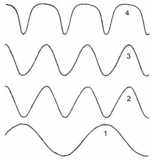
Figure 9.
Dependence of the shape of the output ME signals obtained under the action of an alternating magnetic field with amplitudes of 50 Oe (curve 2), 250 Oe (curve 3), and 800 Oe (curve 4). Reference signal (curve 1).
5. Conclusions
Layered structures of Ni–BaTiO3–Ni were fabricated by gluing. The characteristics of the ME effect in magnetic fields up to 1 kOe are experimentally studied. The maximum value of the linear ME coefficient was 437 mV/(cm Oe) in a magnetizing field of 240 Oe. In this case, a linear dependence of the generated voltage on the amplitude of the alternating magnetic field is observed in the field range from 10−3 Oe to 20 Oe. In the region of electromechanical resonance, a significant increase in the ME coefficient is observed, reaching 32 V/(cm Oe). In the case of a nonlinear ME effect, the frequency is doubled, and the shape of the output signal depends on the amplitude ac magnetic field. The maximum electric field generated in the sample in the signal saturation mode was 70 V/cm. A comprehensive analysis of various types of linear and nonlinear ME effects is carried out in the present work. Linear effects make it possible to observe a direct magnetoelectric interaction in a composite under the influence of a slowly varying constant magnetic field and a small alternating magnetic field that linearizes the effects. Linear ME effects include studies of the field dependence of the ME coefficient, as well as the frequency dependence of the ME coefficient in the resonance region. The maximum value of the ME coefficient and the value of the magnetic field at which it is observed, determined from a field dependence of linear ME effect, serve to determine the range of magnetic fields in which the operation of energy harvesters and magnetic field sensors is most effective.
The study of the resonant dependence of the ME coefficient is necessary, for example, when assessing the prospects for creating magnetic filters controlled by an electric signal, or electric filters excited by a magnetic field. Studies of resonant dependencies form the basis of phase shifters, various types of converters, and bandpass filters. Nonlinear effects include studies of manifestations of ME interactions, which are possible in ME structures in the presence of only an alternating magnetic field. Thus, the interactions manifested are not linearized by an external constant magnetic field. These effects include the study of the field dependence of the electric intensity on the magnetic field, the study of the quadratic field dependence, and characteristic studies of the shape and amplitude of the voltage that occurs in structures under the action of a magnetic field. The maximum electric field generated in the sample in the signal saturation mode, determined from the dependence of the induced electric field on the alternating magnetic field in the absence of a bias field, makes it possible to evaluate the efficiency of energy conversion devices. In addition, the field dependence can be used to calculate the values of the magnetostriction of the magnetic phase of the composite material, as shown in Figure 7. The quadratic dependence of the electric field strength arising in the structure under the influence of a small magnetic field is interesting from the point of view of fundamental research and allows one to judge the nature interactions in a composite material. The dependence of the amplitude and shape of the output ME signals obtained under the action of an alternating magnetic field makes it possible to judge the nature of the ME relationship in the structure under study, which is interesting from the point of view of fundamental research. In addition, data on the shape and amplitude of the signal can be used in the direct experimental development of devices, whose operating principle is based on the ME interaction. Most of the given data were obtained both experimentally and calculated from the existing theory of ME interactions. The above calculations make it possible to replenish and develop the mathematical apparatus of ME interactions, as well as to predict the properties of proposed materials that have not yet been created. One of the factors that prompted the authors to such a comprehensive study of model structures is the desire to show the possibility of using barium titanate ceramics as a worthy and safe replacement for lead-containing ceramics in composite structures exhibiting high magnetoelectric properties. The obtained values of ME characteristics in the Ni–BaTiO3–Ni structure are comparable in magnitude with similar structures based on lead-containing PZT ceramics and allow using the developed structures for designing various electronic elements–magnetic field sensors, recording devices, harvesters, and spintronic devices. In addition to the previously considered microelectronic devices, such materials can be used as safe components for biotechnologies.
Author Contributions
All the authors contributed to this work. Data curation, D.F., V.L., M.K. and N.P.; Formal analysis, D.F., V.L., M.K. and N.P.; Funding acquisition, D.F., V.L. and N.P.; Methodology, V.L., D.F.; and Project administration, D.F.; Writing—original draft, V.L., N.P. and D.F. All authors have read and agreed to the published version of the manuscript.
Funding
The research work was supported by the National Academy of Sciences of Belarus under task 4 “Synthesis, structure and properties of ferroelectric, magnetic and composite materials with high magnetoelectric and dielectric characteristics” of program 1.14. This was conducted at Novgorod State University. Research was funded by a grant from the Russian Science Foundation, project No. 22-19-00763.
Data Availability Statement
Data are available from the corresponding author upon reasonable request.
Conflicts of Interest
The authors declare no conflict of interest.
References
- Bukharaev, A.A.; Zvezdin, A.K.; Pyatakov, A.P.; Fetisov, Y.K. Straintronics: A new trend in micro-, nanoelectronics, and material science. Phys.-Usp. 2018, 61, 1175. [Google Scholar] [CrossRef]
- Tu, C.; Chu, Z.; Spetzler, B.; Hayes, P.; Dong, C.; Liang, X.; Chen, H.; He, Y.; Wei, Y.; Lisenkov, I.; et al. Mechanical-Resonance-Enhanced Thin-Film Magnetoelectric Heterostructures for Magnetometers, Mechanical Antennas, Tunable RF Inductors, and Filters. Materials 2019, 12, 2259. [Google Scholar] [CrossRef] [PubMed]
- Vopson, M.M. Fundamentals of Multiferroic Materials and Their Possible Applications. Crit. Rev. Solid State Mater. Sci. 2015, 40, 223–250. [Google Scholar] [CrossRef]
- Pyatakov, A.P.; Zvezdin, A.K. Magnetoelectric and multiferroic media. Phys.-Usp. 2012, 55, 557. [Google Scholar] [CrossRef]
- Palneedi, H.; Annapureddy, V.; Priya, S.; Ryu, J. Status and Perspectives of Multiferroic Magnetoelectric Composite Materials and Applications. Actuators 2016, 5, 9. [Google Scholar] [CrossRef]
- Ren, S.Q.; Weng, L.Q.; Song, S.-H.; Li, F.; Wan, J.G.; Zeng, M. BaTiO3/CoFe2O4 particulate composites with large high frequency magnetoelectric response. J. Mater. Sci. 2005, 40, 4375–4378. [Google Scholar] [CrossRef]
- Ryu, J.; Carazo, A.V.; Uchino, K.; Kim, H.-J. Piezoelectric and Magnetoelectric Properties of Lead Zirconate Titanate/Ni-Ferrite Particulate Composite. J. Electroceramics 2001, 7, 17–24. [Google Scholar] [CrossRef]
- Zhai, J.; Xing, Z.; Dong, S.; Li, J.; Viehland, D. Magnetoelectric laminate composites: An overview. J. Am. Ceram. Soc. 2008, 91, 351–358. [Google Scholar] [CrossRef]
- Chu, Z.; Asl, M.J.P.; Dong, S. Review of multi-layered magnetoelectric composite materials and devices applications. J. Phys. D Appl. Phys. 2018, 51, 243001. [Google Scholar] [CrossRef]
- Ma, J.; Hu, J.; Li, Z.; Nan, C.W. Recent progress in multiferroic magnetoelectric composites: From bulk to thin films. Adv. Mater. 2011, 23, 1062–1087. [Google Scholar] [CrossRef]
- Geng, D.; Yan, Y.; Priya, S.; Wang, Y. Electric Field Control of Magnetic Permeability in Co-Fired Laminate Magnetoelectric Composites: A Phase-Field Study for Voltage Tunable Inductor Applications. ACS Appl. Mater. Interfaces 2020, 12, 44981–44990. [Google Scholar] [CrossRef]
- Ramesh, R.; Manipatruni, S. Electric field control of magnetism. Proc. R. Soc. A 2021, 477, 20200942. [Google Scholar] [CrossRef]
- Liu, H.J.; Liang, W.I.; Chu, Y.H.; Zheng, H.; Ramesh, R. Self-assembled vertical heteroepitaxial nanostructures: From growth to functionalities. MRS Commun. 2014, 4, 31–44. [Google Scholar] [CrossRef]
- Liang, X.; Chen, H.; Sun, N.X. Magnetoelectric materials and devices. APL Mater. 2021, 9, 041114. [Google Scholar] [CrossRef]
- Filippov, D.; Liu, Y.; Zhou, P.; Ge, B.; Liu, J.; Zhang, J.; Zhang, T.; Srinivasan, G. Low-Frequency Magnetoelectric Effects in Magnetostrictive–Piezoelectric Bilayers: Longitudinal and Bending Deformations. J. Compos. Sci. 2021, 5, 287. [Google Scholar] [CrossRef]
- Filippov, D.A. Theory of magnetoelectric effect in ferromagnetic-piezoelectric bilayer structures. Tech. Phys. Lett. 2004, 30, 983–986. [Google Scholar] [CrossRef]
- Bichurin, M.I.; Filippov, D.A.; Petrov, V.M.; Laletsin, V.M.; Paddubnaya, N.N.; Srinivasan, G. Resonance magnetoelectric effects in layered magnetostrictive-piezoelectric composites. Phys. Rev. B 2003, 68, 132408. [Google Scholar] [CrossRef]
- Laletin, V.M.; Paddubnaya, N.N.; Srinivasan, G.; De Vreugd, C.P.; Bichurin, M.I.; Petrov, V.M.; Filippov, D.A. Frequency and field dependence of magnetoelectric interactions in layered ferromagnetic transition metal-piezoelectric lead zirconate titanate. Appl. Phys. Lett. 2005, 87, 222507. [Google Scholar] [CrossRef]
- Filippov, D.A.; Laletin, V.M.; Poddubnaya, N.N.; Shvartsman, V.V.; Lupascu, D.C.; Zhang, J.; Srinivasan, G. Magnetostriction via Magnetoelectricity: Using Magnetoelectric Response to Determine the Magnetostriction Characteristics of Composite Multiferroics. Tech. Phys. Lett. 2019, 45, 1152–1154. [Google Scholar] [CrossRef]
- Laletin, V.M.; Filippov, D.A.; Firsova, T.O. The nonlinear resonance magnetoelectric effect in magnetostrictive-piezoelectric structures. Tech. Phys. Lett. 2014, 40, 237–240. [Google Scholar] [CrossRef]
- Burdin, D.A.; Chashin, D.V.; Ekonomov, D.V.; Gordeev, S.N.; Fetisov, Y.K. Nonlinear magnetoelectric effect in a layered ferromagnetic-piezoelectric heterostructure excited by transverse magnetic field. Appl. Phys. Lett. 2020, 116, 072901. [Google Scholar] [CrossRef]
- Fetisov, L.Y.; Baraban, I.A.; Fetisov, Y.K.; Burdin, D.A.; Vopson, M.M. Nonlinear magnetoelectric effects in flexible composite ferromagnetic—Piezopolymer structures. J. Magn. Magn. Mater. 2017, 441, 628–634. [Google Scholar] [CrossRef]


Disclaimer/Publisher’s Note: The statements, opinions and data contained in all publications are solely those of the individual author(s) and contributor(s) and not of MDPI and/or the editor(s). MDPI and/or the editor(s) disclaim responsibility for any injury to people or property resulting from any ideas, methods, instructions or products referred to in the content. |
© 2023 by the authors. Licensee MDPI, Basel, Switzerland. This article is an open access article distributed under the terms and conditions of the Creative Commons Attribution (CC BY) license (https://creativecommons.org/licenses/by/4.0/).