Article

Experimental and Numerical Analysis of Axial Behavior of Triaxial Woven Fabric Confined Concrete Columns

by
Muhammad Usman Ghani
1,2,
Tingting Sun
1,2,
Honghua Zhang
1,2,
Kahsay Gebresilassie Abraha
1,2,3,
Nauman Ahmad
4,
Khalil Ahmed
4,
Rehan Saeed
5,
Mohmadarslan Kutubuddin Sadannavar
6 and
Wei Li
1,2,7,*
1
College of Textiles, Donghua University, Shanghai 201620, China
2
Key Lab of Textile Science & Technology, Ministry of Education, Shanghai 201620, China
3
Department of Textile Engineering, Aksum University, Aksum P.O. Box 1010, Tigrai, Ethiopia
4
Department of Civil Engineering, Tongji University, Shanghai 200092, China
5
Department of Automation, School of Information Science and Technology, University of Science and Technology of China (USTC), Hefei 230027, China
6
College of Chemistry, Chemical Engineering, Donghua University, Shanghai 201620, China
7
Center for Civil Aviation Composites, Donghua University, Shanghai 201620, China
*
Author to whom correspondence should be addressed.
J. Compos. Sci. 2023, 7(9), 358; https://doi.org/10.3390/jcs7090358
Submission received: 27 July 2023 / Revised: 14 August 2023 / Accepted: 21 August 2023 / Published: 25 August 2023
(This article belongs to the Section Composites Modelling and Characterization)

Abstract

:
Continuous efforts are being made to improve plain concrete compressive strength and ductility by applying carbon, glass fiber, or hybrid-reinforced epoxy resin composites. The investigation centers on analyzing the axial compressive strength and strain, compressive stress–strain behavior, failure morphology, and crack evolution of the reinforced cylinders. Besides the experiments, non-linear finite element analysis was performed using the finite element (FE) package ABAQUS 2021. The test results indicate that carbon fiber triaxial woven fabric (TWF-C) confinement result in the most significant improvement of 118% in compressive stress than the concrete specimens. On the other hand, glass fiber triaxial woven fabric (TWF-G) confinement shows the highest enhancement of 161% in ductility. The mechanical properties of the sample utilizing glass fiber as the weft yarn and carbon fiber as the warp yarn (TWF-GC2) exhibit superior improvements of 22% in compressive stress and 8% in axial strain compared to the sample using glass fiber as the warp yarn and carbon fiber as the weft yarn (TWF-CG2). Samples with glass fiber as weft yarn show gradual cracks during loading, while carbon fiber as weft yarn show instantaneous damage. The numerical finite element models accurately predict the experimental results of the tested specimens in this study. There were 1.2~3% and 5~10% discrepancies for compressive stress and axial strain, respectively, between experimental and FE results. Overall, the results suggest that Triaxial woven fabric confinement is a valuable technique to improve the strength and strain of concrete and that the type of fibers used could be tailored for appropriate performance characteristics.

1. Introduction

Fiber-reinforced polymers have gained popularity in structural engineering and are increasingly used for supporting and repairing existing concrete constructions [1]. This technique has gained global recognition for externally enhancing columns’ axial and load-bearing capacities when internal reinforcement is insufficient [2]. Over time, concrete structures deteriorate due to environmental interactions. Repair and strengthening using fiber-reinforced polymers have been widely accepted as viable engineering solutions to extend the service life of defective structures. These techniques result in improved load-carrying capacity and deformation capabilities [3]. FRPs offer advantages such as increased strength [4], enhanced stiffness, improved durability, and easy installation. The structural member’s geometry and shape influence FRP wrapping’s effectiveness in confining structures. Circular columns are crucial in allowing fibers to be effective throughout the entire cross-section [5]. This technique strengthens the structures and enhances their ductility.
The compressive strength of unreinforced concrete, the elastic modulus, the thickness of the FRP, and the fiber orientation inside the FRP laminates are some variables that control the confinement effectiveness [6]. Less consideration has, however, been devoted to how fiber orientation affects the behavior of concrete reinforced with FRP laminates [3]. The mechanical performance of FRP laminates can be raised by positioning the fibers along the ideal direction [7]. As a result, it is essential to guarantee optimal fiber orientation while reinforcing each structural element and modifying it according to the element’s internal stress distribution.
It is widely known that fibers should be oriented in the horizontal direction for concrete columns exposed to uniaxial compressive force to prevent the concrete core from expanding under compression [8]. In such circumstances, mats made of unidirectional polymer fibers are frequently employed for strengthening. Axis-aligned fibers have been the subject of most investigations on FRP-confined concrete columns because of the anticipated advantages in terms of increased axial capacity and simplicity. However, some studies have investigated the impact of inclined fiber orientations [3,9] exceeding 15° relative to the hoop direction, such as distinct layering arrangements of cross-ply FRP wrappings (e.g., 45° and 90°) or various winding approaches in the case of concrete-filled FRP tubes (CFFTs), when concrete columns made of FRP were subjected to cyclic loads. For example, Sadeghian et al. [10] investigated the performance of the columns via inclined fiber angles. It was discovered that using inclined fiber angles lessens the strength improvement via FRP confinement and increases the ductility of confined columns, which may be advantageous in seismic cycle loadings. In a related experimental work, Piekarczyk [11] found that inclined fiber angles increased ductility. The above research did not discuss the effects of altered fiber orientation on the behavior of reinforced concrete. Other research has, however, studied this issue. For instance, the authors of these research articles [7,12,13] and two numerical investigations [14,15] have analyzed different FRP stacking sequence configurations with fibers inclined at different angles (such as 30°, 45°, 60°, 0°/45°, etc.) and found that the presence of hoop fibers tends to increase strength.
In contrast, inclined, cross-ply fibers help to enhance ductility. The mentioned studies found that angular cross-ply FRP wraps with specific ply mix sequences contribute to enhanced ductility through fiber re-orientation mechanisms but do not significantly improve strength. In the research conducted by Seffo M. et al. [16], a critical finding emerged. Their experimental results demonstrated a direct correlation between the number of fabric layers and the strength of confined concrete columns. Ahmed Sulaiman et al. [12] conducted an ongoing study to assess the influences of fiber orientation and stacking order on the behavior of FRP-confined concrete. According to their published findings, the samples were constrained using different CFRP stacking configurations, with the fibers oriented at 0°, 90°, and 3:45°. Micelli et al. [17] conducted studies investigating the influence of different parameters on the efficiency of FRP confinement using carbon fibers and glass fibers. It was found that fiber orientation is a crucial parameter that influences both the strength and ductility of CFRP-confined concrete.
Triaxial woven fabric (TWF) is a type of fabric characterized by three sets of yarns interwoven at an angle of 60 degrees, consisting of two sets of warp yarns and one set of weft yarns, forming a stable structure [18]. This material features hexagonal holes and three-directional fibers, which has led to significant interest in TWF due to its lightweight nature and isotropic mechanical properties [19,20]. In applications such as the aerospace industry, composites made from the triaxial woven fabric of carbon fiber (CFTWFC) are utilized as ultrathin materials, distributing loads evenly and providing favorable properties. TWF has been used in many areas, such as aerospace, sports equipment, and high-level security [16]. Researchers worldwide [17] have studied mechanical properties [21,22,23], thermal properties [24], mathematical analysis [25], and finite element simulation of TWF and its composite materials [26]. Jia Minghao [18] studied the flexural qualities of basalt fiber plane triaxial woven-fabric-reinforced cement and its composite materials. The study found that triaxial woven-fabric-reinforced concrete has twice the flexural modulus of regular concrete [19]. However, to the author’s best knowledge, no studies have been found in the literature involving concrete confinement via Triaxial woven fabric.
To this end, the present study focuses on experiments to analyze the axial behavior of concrete columns confined by Triaxial woven fabric. Triaxial woven fabrics are manufactured using two types of fibers, namely carbon and glass fibers, as well as their hybrids. The primary goal of this study is to measure the effectiveness of externally confined TWF wraps in strengthening circular cylinders with lower unconfined concrete strengths, such as 14.6 MPa. The secondary goal is to study the impact of hybrid Triaxial woven fabric (TWF) on concrete behavior and the mechanics of confined cylinders. Numerical methods were also employed to assess the performance of Triaxial woven fabric (TWF) composite as reinforcing materials for concrete columns under axial loading.

2. Materials and Methods

2.1. Raw Materials

2.1.1. Triaxial Woven Fabric

The triaxial woven fabric used in the experiment was made of T300-12K carbon fiber and 1200 tex alkali-free glass fiber. The structure of the Triaxial woven fabric is shown in Figure 1. The warp and weft density of TWF was 10.8 ends per 20 cm, whereas fabric porosity was 34.3%. The carbon and glass fabric thicknesses were 0.5 mm and 0.7 mm, respectively. The width of the yarns was 6 mm.

2.1.2. Concrete Column

The raw materials used to prepare concrete samples were Portland cement of grade 42.5, coarse aggregate of 10–20 mm in size, and river sand. A PVC mold 70 mm in diameter and 140 mm in height was selected for casting the concrete specimens. The mix ratio was chosen based on the conventional concrete mix ratio design specification: cement: sand: coarse aggregate: water = 1:2.37:3.77:0.67. Releasing agent was applied to the mold to speed up the demolding procedure before pouring the concrete. First, half of the concrete’s volume was poured into the mold, and then the mold was thoroughly vibrated on the vibration table. The remaining concrete was added to the mold and vibrated to ensure uniformity. A shovel was used to remove extra concrete and level it up. All specimens of concrete were cast with the same batch of mixed proportions. Concrete samples were de-molded 24 h after casting and kept for 28 days in water for curing.

2.2. Confinement of Concrete

Each concrete column was sanded and cleaned before the triaxial woven fabric wrapped around the concrete columns, as shown in Figure 2. Epoxy resin was bought from Shangwei (Tianjin, China) Wind Power Materials Co., Ltd. The mass proportion of the matrix to the curing agent was 3:1. The mechanical properties of the epoxy resin can be found in Table 1. Then, the epoxy was applied evenly on the surface of the yarns of triaxial woven fabric with a brush. A wrapping cloth was used to absorb the excess amount of resin. After the samples were cured at room temperature for 12 h, they were post-hardened at 70° in the oven for 6 h.
The samples are divided into five groups and one pure concrete without any reinforcement as the control group. The other four groups are divided into carbon fiber (TWF-C), glass fiber (TWF-G), and carbon-glass hybrid groups according to the yarn’s direction used in the triaxial woven fabric (TWF-CG2 and TWF-GC2). In the carbon-glass hybrid group, the samples whose warp yarns are glass fibers, the weft yarns are carbon fibers are named TWF-CG2 group, and the samples whose warp yarns are carbon fibers and weft yarns are glass fibers are named TWF-GC2 group, as can be seen in Figure 2. The tops of all concrete columns were levelled with a grinder to ensure that the concrete columns were evenly stressed so that the material avoided off-axis compression. Three identical specimens were used in testing to confirm the test results’ validity and the average value has been calculated. Upper and lower confidence index values were calculated with a confidence index level of 95%.

2.3. Equipment and Instruments

The compression experiment was conducted on the Lanbo Sansi LD26 electro-hydraulic servo universal testing machine. The control displacement method was adopted, and the loading rate was 2 mm/min up to 40% loading.

3. Non-Linear Finite Element Analysis

3.1. Materials Modelling for the FE Model

3.1.1. Geometric Model of Triaxial Woven Fabric

Triaxial woven fabric consists of three sets of yarn interlaced at a 60-degree angle from each other. For this study, SolidWorks® 2019 was used to create models of the TWF based on the yarn’s cross-section and path, which closely resembled the actual specimen, as depicted in Figure 3.

3.1.2. Modeling of TWF Materials

The geometry of the Triaxial Woven Fabric (TWF) yarns was approximated utilizing shell elements (S4R) in the present Finite Element Analysis (FEA) modelling. It is crucial to characterize laminate strength, elastic characteristics, and damage development to appropriately depict the behavior of FRP wraps. Composite structures pose a complex and challenging task when identifying and detecting internal damage patterns [27]. Intralaminar damage occurs within the sheet and involves fiber tensile and compressive failure modes. Matrix tensile and compressive failure modes may be used to classify the damage received by FRP sheets [28]. Delamination or interlaminar damage between neighboring layers falls under the second type. The misalignment of the fibers and the resin’s shear behavior significantly impacts the degree of damage in composites. Transverse fractures that cause damage to the matrix or fiber interfacial areas might appear under tensile stress. According to the experimental results, matrix shear damage rather than matrix compression damage predominates, causing a fracture plane to develop along the fiber’s through-thickness direction [29]. The elastic behavior of TWF yarns was simulated with the help of the “Engineering Constants” material type. The specific properties used to describe the engineering constants are given in Table 2.
Failure modes of FRP laminates were simulated using the Hashin damage criterion in the present research [31]. This criterion accurately predicts tensile and compressive damage initiation in the fiber and matrix [28]. The strength of the TWF composites were specified based on the tensile strength. The stiffness coefficients’ degradation occurs under other loadings upon the damage criterion’s initiation. The progression of damage parameters in the FRP material was determined using energy release rates for four damage modes [32], as reported by [28]. The factors used to designate the Hashin damage model for FRP composites can be found in Table 3.

3.2. Modeling of Concrete

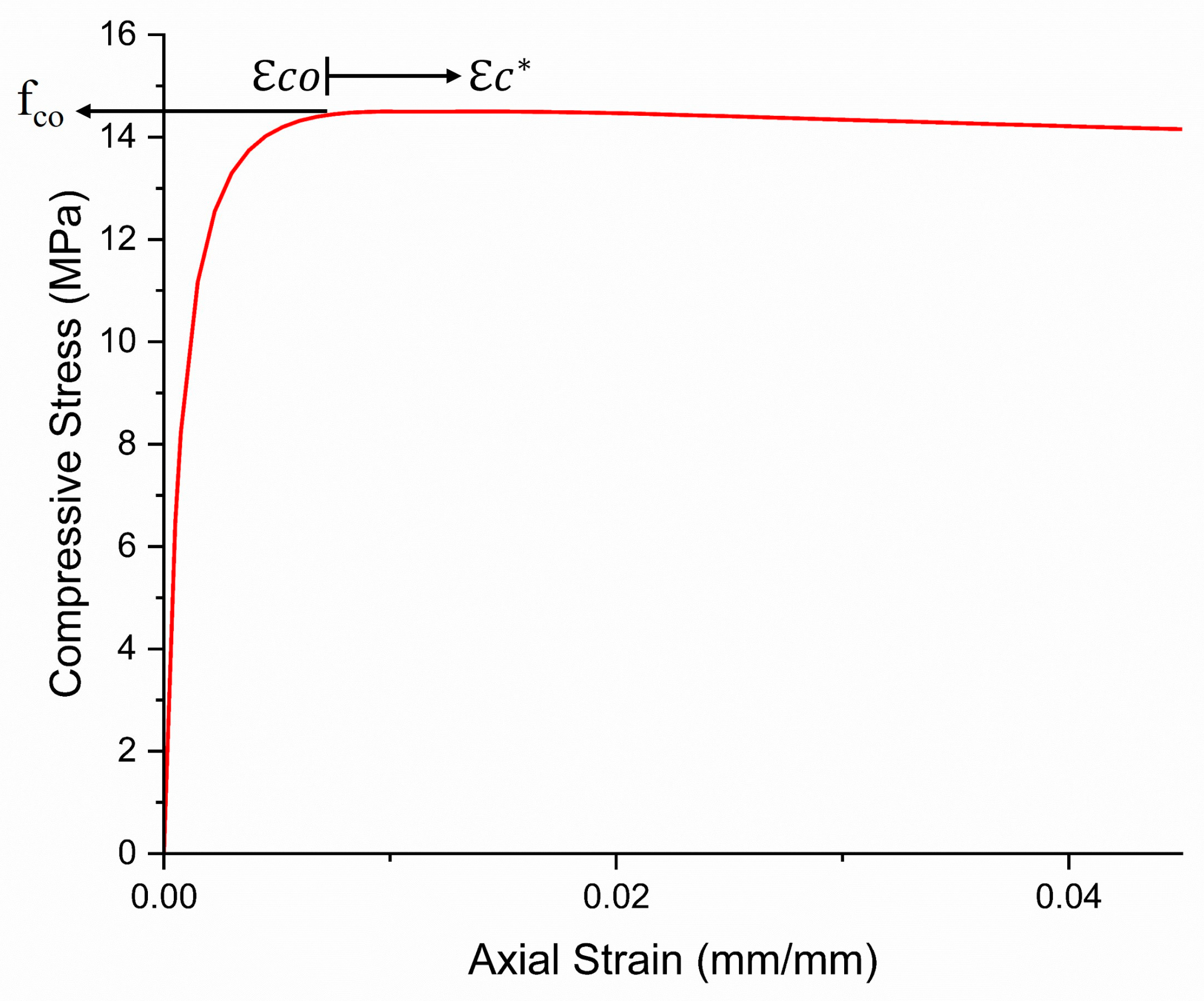
ABAQUS is a robust concrete material analysis software that provides three different models: the plastic damage model, the brittle crack model, and the diffuse crack model. The concrete damage plasticity (CDP) model is widely favored among these options because of its comprehensive approach to capturing concrete’s 3D nonlinear inelastic behavior. The CDP model incorporates critical aspects such as confinement, damage mechanisms, and behavior of concrete in compression, tension, and plasticity in the inelastic range. In contrast, the smear crack model mainly focuses on crack formation, with plastic strains affected by the compressive yield surface. However, brittle crack models place less emphasis on compression failure. When aiming to model the behavior of FRP-confined concrete accurately, it is clear that relying solely on the stress–strain curves of unconfined concrete is insufficient. Hence, the concrete material was modeled as confined concrete, utilizing the axial stress and strain models for fiber-reinforced polymer (FRP)-confined concrete as proposed by Ferrotto et al. [34] with necessary adjustments made to the CDP (Concrete Damage Plasticity) model. The equivalent stress–strain curve for confined concrete, shown in Figure 4, was adopted from their work. In this curve, “fco” represents the axial compressive stress for concrete behavior under confinement, and “εco” represents the compressive strain at “fco”. This model provides a comprehensive representation of the behavior of confined concrete, which can be summarized as follows. The development of the model began by modifying the stress–strain relationship originally proposed by Popovics [35].
The model considers three different branches of the stress–strain curve, each representing a different phase of the behavior of the confined concrete. The stress–strain curve’s first branch represents the confined concrete’s behavior up to the unconfined concrete strength/strain point (fco, εco), which remains constant. The strain value increases (from εco to εc*) at a constant stress level of fco. The softening branch is the third branch of the curve, which is defined according to the method proposed by Popovics [35], substituting εc* for εco. In summary, the following equations describe the three branches of the proposed stress–strain curve.
σ f c o = x 1 · r 1 r 1 1 + x 1 r 1   for   0 c o
σ f c o = 1   for   c *
σ f c o = x 2 · r 2 r 2 1 + x 2 r 2   for   *
x 1 = c o
x 2 = c *
r 1 = E c E c E s c e , 1
r 2 = E c E c E s c e , 2
E s e c , 1 = f c o c o
E s c e , 2 = f c o c *
c * = c o + k ·
k · = 0.00065 + 0.0007 · ω
ω = 4 · t f r p · E f r p · j u D · f c o
In this context, Esec,1 and Esec,2 represent the secant elastic moduli at εco and εc*, respectively. The remaining parameters are provided in [35].
The specimen possesses the following dimensions: diameter (d) of 70 mm, and height (h) of 140 mm. The unconfined concrete strength (fco) is 14.6 MPa, accompanied by a strain at unconfined peak stress (εco) of 0.011. The thickness of the carbon and glass fiber TWF jacket (tf) is 0.5 mm and 0.7 mm, respectively. The tensile modulus (Efrp) and failure strain (εju) of the carbon and glass fiber was 105 GPa and 1.3% and 40 GPa and 1.9%, respectively.
Poisson’s ratio was taken as 0.2 for all the simulated concrete. To define the modified stress–strain (σ–ε) relationship used for Finite Element (FE) analysis, the axial elastic modulus of concrete was computed based on the methodology proposed by Mander et al. [36] with Equation (13).
E c = 5000 f c o 0.5
The ABAQUS standard simulated a confined concrete core’s nonlinear plasticity and damage behavior using a customized Concrete Damage Plasticity (CDP) model version. The modified CDP model addresses concrete’s plastic, compressive and tensile behavior.
To effectively characterize the plastic behavior of confined concrete, the model integrates essential components such as flow rules, yield surface functions, and softening/hardening laws. This behavior was modeled by incorporating various parameters, including the shape coefficient (Kc), biaxial to triaxial compressive strength (fbo/fco) ratio, potential eccentricity, viscosity parameter, and concrete expansion angle. These parameters collectively play crucial roles in accurately describing the material’s response. These parameters did not affect the stress–strain curve, so the default values were used as described in Table 4. In order to simulate the compressive behavior of concrete, the inelastic strain (in) is further augmented to delineate compressive failure at larger strains and peak stresses. The compression behavior of the material encompasses both compression damage and compression hardening. Under cyclic loading conditions, the compression damage variable plays a significant role in inducing the degradation of the elastic stiffness of FRP-confined concrete. However, in the case of monotonic loading, the influence of the compression damage variable is negligible. As a result, compression damage was not utilized for the present study. The numerical simulations of the tensile behavior of the confined concrete core material in the CDP model were performed using the tension stiffening model [37] adapted by Wahalathantri et al. [38]. The implementation of this model is illustrated in Figure 5. Additionally, the ultimate tensile stress (σt) of concrete was determined using the equation proposed by Genikomsou and Maria Annax [39].
  σ t = 0.33 f c M P a

3.3. FEA Methodology

The commercial program, ABAQUS, was used in the current study to develop a finite element model (FEM), an effective method for studying reinforced concrete structures that can precisely forecast the behavior of TWF-confined columns. The modified material models for constrained concrete and FRP material were employed in the current investigation. Without being overly complex, which would increase analysis time, the numerical model needs to be rich enough to capture the fundamental processes of the structural component. Firstly, the TWF tube model was imported into Abaqus and assembled with concrete and load platen. Suitable mesh elements were assigned to the parts. The material properties were assigned to the related parts. The confined concrete material and steel plates were modeled using deformable three-dimensional stress solid brick components with eight nodes and reduced integration (C3D8R). The FRP yarns were represented by deformable 4-noded doubly curved shell elements with hourglass control and reduced integration (S4R). To ensure accurate simulation, a hard contact in the normal direction and frictional contact with a friction coefficient of 0.25 in the tangential direction were specified to prevent piercing between the outer concrete surface and the inner steel tube surface [40]. The interaction between the inner surface of the TWF yarns confining component and the concrete part was simulated by a perfect bonding using tied constraint, ensuring corresponding nodes experience similar translations. This was considered because tie constraints connect the FRP to the concrete, distributing stresses more evenly across the interface and lowering localized stress concentrations that can cause early failure. A general contact algorithm was employed to assign contact among TWF yarns. The bottom end of all columns was restricted to all degrees of freedom (DOF). Displacement control was utilized for the FEA models of all columns, with equally distributed axial stress imposed on the upper steel plate. One of the TWF confined columns (TWF-C) was selected as a control specimen for calibration and validation. The FEA model of TWF-C was adjusted for various boundary conditions, geometric properties, and material properties to achieve accurate results, effectively matching experimental data on axial capacity, stress–strain behavior, and failure patterns. Through careful analysis and selection, an excellent agreement between experimental and FEA predictions of the stress–strain curve was achieved using 10 mm elements for concrete and 3 mm mesh size for TWF yarns. These elements were chosen for further analysis of the TWF confined columns.

4. Results and Discussion

4.1. Stress–Strain Behavior of Concrete Column Confined by TWF

The stress–strain curves portraying the average values from each group of TWF-confined concrete columns are illustrated in Diagram 6. It can be seen that there is no strain softening, which indicates that a certain level of confinement has been achieved. From Figure 6, it can be observed that the stress–strain curves can be divided into three branches. The curves display a typical bilinear pattern, with strain hardening leading up to failure caused by the rupture of FRP. In the beginning, the first portion of the curve demonstrates a linear behavior dominated by the strength of the unconfined concrete, indicating that the FRP confinement had not yet been activated due to the negligible lateral expansion in the concrete. A non-linear reaction was produced in the transition zone due to the continuing dilation of the concrete, which caused lateral strains to increase. FRP confinement was activated once the maximal strength of the unconfined concrete had been reached (fco = 14.6 MPa), which was possible because of the sufficient level of lateral confinement. At this point, further fractures began to emerge, which resulted in a decrease in the rigidity of the concrete. The curve continued to expand linearly with a moderate slope until it failed. The concrete was fractured at this point, and the TWF confinement provided additional load-carrying capacity. Brittle concrete exhibits a behavior known as strain hardening, which considerably boosts both the compressive strength and ductility of the material. According to the findings shown in Figure 6, specimens wrapped with a hybrid of glass and carbon fibers along both the weft and warp directions behave very similarly to specimens with fibers only arranged in the warp orientation. Despite the incorporation of fibers in the weft direction, the warp direction has the most significant impact on the strength and stiffness of the wrapped specimens.

4.2. Effect of TWF Confinement on Compressive Stress and Axial Strain

The experimental results outlined in Table 5 demonstrate a significant enhancement in ultimate strengths and strains of the specimens due to TWF confinement. Here, fcc and fco represent the ultimate strengths of confined and unconfined concrete, respectively, while εcc and εco represent the ultimate axial strains of confined and plain concrete. Table 5 shows that TWF-C exhibited the highest compressive strength, followed in descending order by TWF-GC2, TWF-CG2, and TWF-G. This performance improvement can be attributed to the inherent characteristics of the carbon fiber fabric, which exhibits commendable tensile strength and a high elastic modulus. The primary function of CFRP composite materials lies in their ability to effectively confine the concrete, thereby providing a greater reserve of strength and ductility. This confinement effect plays a crucial role in enhancing the confined concrete specimens’ overall structural behavior and performance [41]. The axial strain had a distinct order, with TWF g having the maximum axial strain and being followed in declining order by TWF-CG2, TWF-GC2, and TWF-C. This enhancement of axial strain might be due to less-stiff higher-elongation glass fiber.
The carbon fiber-wrapped TWF-confined columns showed the most significant improvement, outperforming the control specimen in strength and axial strain by 118% and 100%, respectively. Comparing the confined samples with TWF g to the unconfined samples, the confined samples’ compressive strength and axial strain increased by about 69% and 161%, respectively. TWF-GC2 specimen showed an increase in compressive strength and axial strain by 108% and 131%, respectively, compared to the control specimen. In contrast, the specimens reinforced by TWF-CG2 displayed an increase in compressive stress of 70% and an increase in axial strain of 117%.
TWF-GC2 showed the most significant improvement among the confined hybrid specimens compared to TWF-C, with just a 10.7% drop in compressive strength, which was insignificant given the cost savings in the materials utilized. Furthermore, the axial strain enhancement of TWF-GC2 was 25% more than the increase seen in TWF-C. These findings imply that the fibers along the warp (transverse direction) affect compressive stress, and that fibers along the weft direction (longitudinal direction) have effects on the strain, as seen in hybrid specimens [42]. The increase in compressive stress is reduced when the glass fiber is along the warp direction than when the carbon fiber is along the warp direction. Likewise, the increase in axial strain is reduced when the carbon fiber is along the weft direction than when the glass fiber is along the weft direction. This can be linked to the strength loss brought on by the transversely utilized fiber strength, which was less effective at preventing lateral expansion of concrete.
Using TWF for concrete confinement significantly improves strength and ductility behaviors. Particularly, reinforcing glass fibers significantly increases the ductility of cylindrical concrete specimens, while strengthening with carbon fibers increases strength. TWF-GC2, one of the two mixed groups examined, shows a significant improvement in ultimate failure stress value, despite having relatively moderate axial strain fluctuation compared to the other groups. Overall, the results show that TWF confinement is a helpful technique for enhancing concrete strength and ductility. The type of fiber employed may be customized to obtain the appropriate performance characteristics.

4.3. Failure Mode

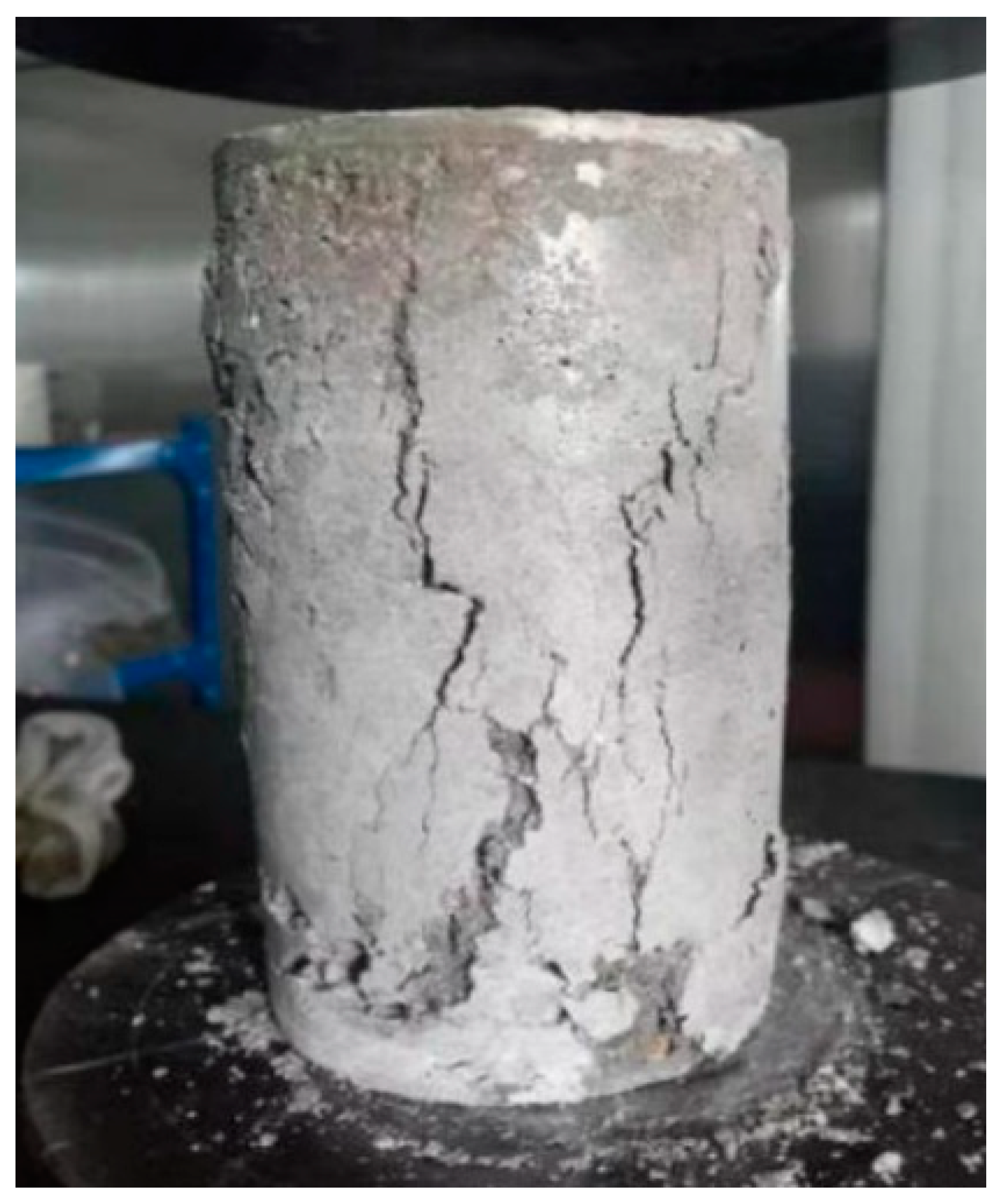
The failure mode of the control specimen is shown in Figure 7. Due to the little axial force at the initial loading stage, there did not appear to be any surface damage in the case of the unconstrained concrete column. On the upper surface of the cylinder, multiple parallel vertical microcracks started to form as the axial load reached about 40% of the peak load because of the interfacial transition zone. The initial cracks spread considerably, and new cracks began to form rapidly at about 80% of the peak load. These cracks progressively widened and spread to the lowest portion of the column, making quiet cracking noises. When the weight reached its apex, the concrete column’s principal vertical crack quickly pierced the full height of the column, splitting the column and producing an audible bursting sound. The specimen’s bearing capacity abruptly decreased and exhibited brittle failure features.
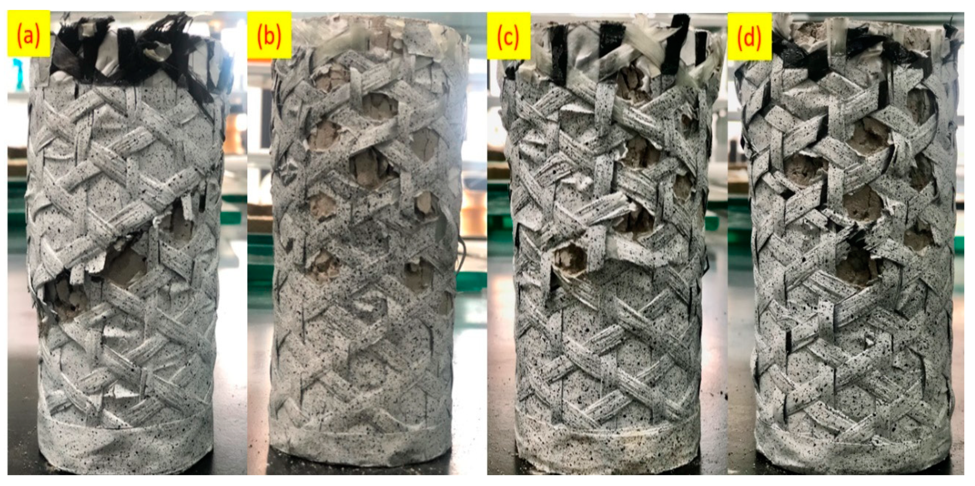
Figure 8 shows the failure morphology of compressed TWF-confined concrete samples. The load-bearing performance of the samples in the confined groups was the same in the early loading stage. However, as the loading progressed, the samples in each group gradually showed different types of crack propagation accompanied by brittleness in the middle and late stages.
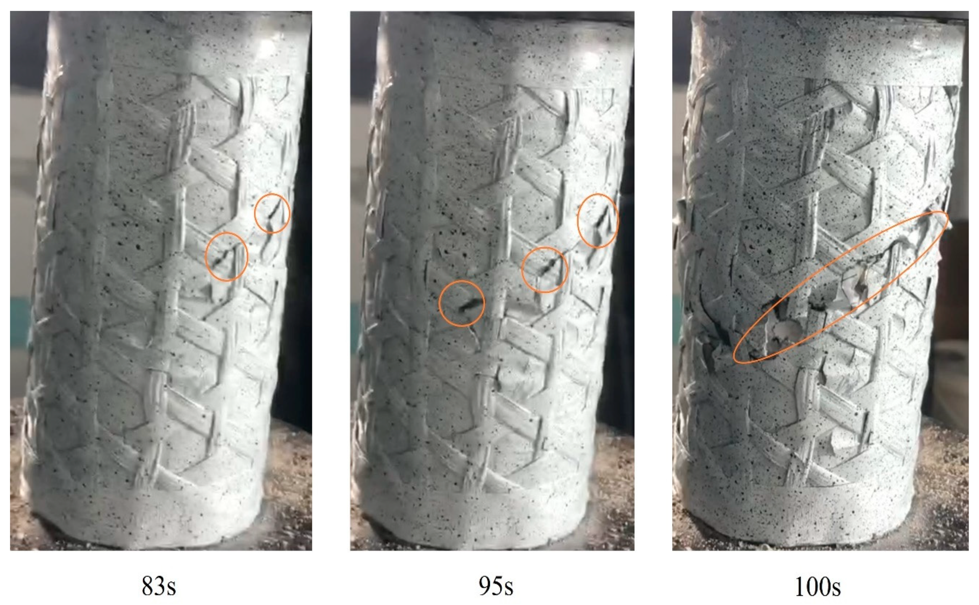
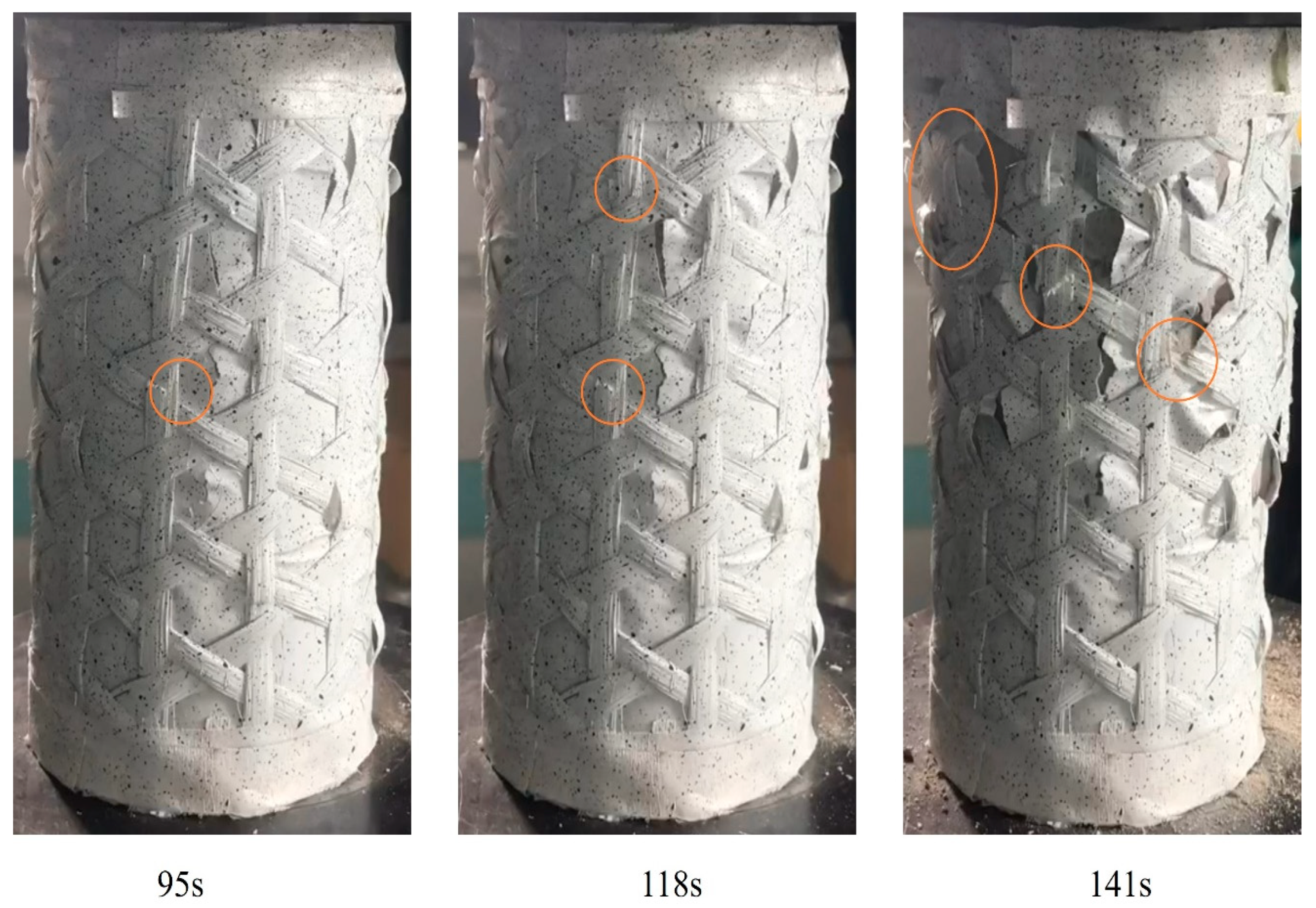
Cracks appear suddenly in the sample and rapidly expand and connect quickly, eventually leading to the failure of the sample. Such failure mode is defined as “instantaneous” failure. Carbon fiber possesses superior stiffness and strength, resulting in rapid crack propagation and instantaneous failure. As shown in Figure 9, for TWF-C, only small cracks appear on the sample surface before 83s. Cracks expand and appear instantaneously at 95s and continue to expand, and around 100s, the cracks expand again, causing the sample to fail, and the carrying capacity of the sample was further reduced.
The fracture lines of the glass fiber group samples are generally along the longitudinal direction. Cracks appear in the middle loading stage and gradually expand until the fibers are completely broken. It took a long time from the crack to the complete failure of the sample. According to the crack morphology, the damage of the glass fiber group during the loading process is mainly caused by the hoop tensile force. Glass fiber tends to exhibit higher ductility and energy absorption capacity, allowing for a gradual crack propagation mechanism, as shown in Figure 10, the failure mode of this group of samples is “progressive” failure, and the crack expansion speed is relatively slow, so this group of samples shows a good improvement in ductility.
The fracture patterns of samples in group CG2 are diagonal and vertical, and the warp and weft yarns have greater damage. Small cracks first appear in the weft yarns in the middle of loading, and small-scale fractures appear in the warp yarns. As the loading progresses, the warp yarn cracks expand and break, and the weft yarns become brittle and break, causing the sample to fail quickly. The weft carbon fiber is subjected to axial shear force transmitted by interfacial bonding, and the warp glass fiber is subjected to hoop tensile force. As shown in Figure 11, the crack growth tendency of the samples of the CG2 group is similar to that of the carbon fiber group in the mid-loading stage, and the crack growth rate is relatively fast. When the small cracks are connected to large cracks, the failure trend is similar to that of the TWF-C group, which belongs to “instantaneous” destruction.
The fractures of the samples in the TWF-GC2 group were scattered and did not connect into prominent fracture lines, and the degree of sample damage was smaller than that of the other three groups. During the loading process, the weft yarns were first compressed, the damage degree was small, and then longitudinal cracks appeared on the warp yarns, which started spreading slowly. As shown in Figure 12, the crack growth rate of the samples in the TWF-GC2 group is slower, and the time from the appearance of small cracks to the expansion of large cracks leading to the failure of the sample is more extensive, which is similar to the crack growth trend of the samples in the TWF-C group. The differences in failure morphology and crack evolution can be attributed to glass fiber and carbon fiber’s contrasting tensile and shear properties.

4.4. Comparative Analysis of Experimental and Simulated Results

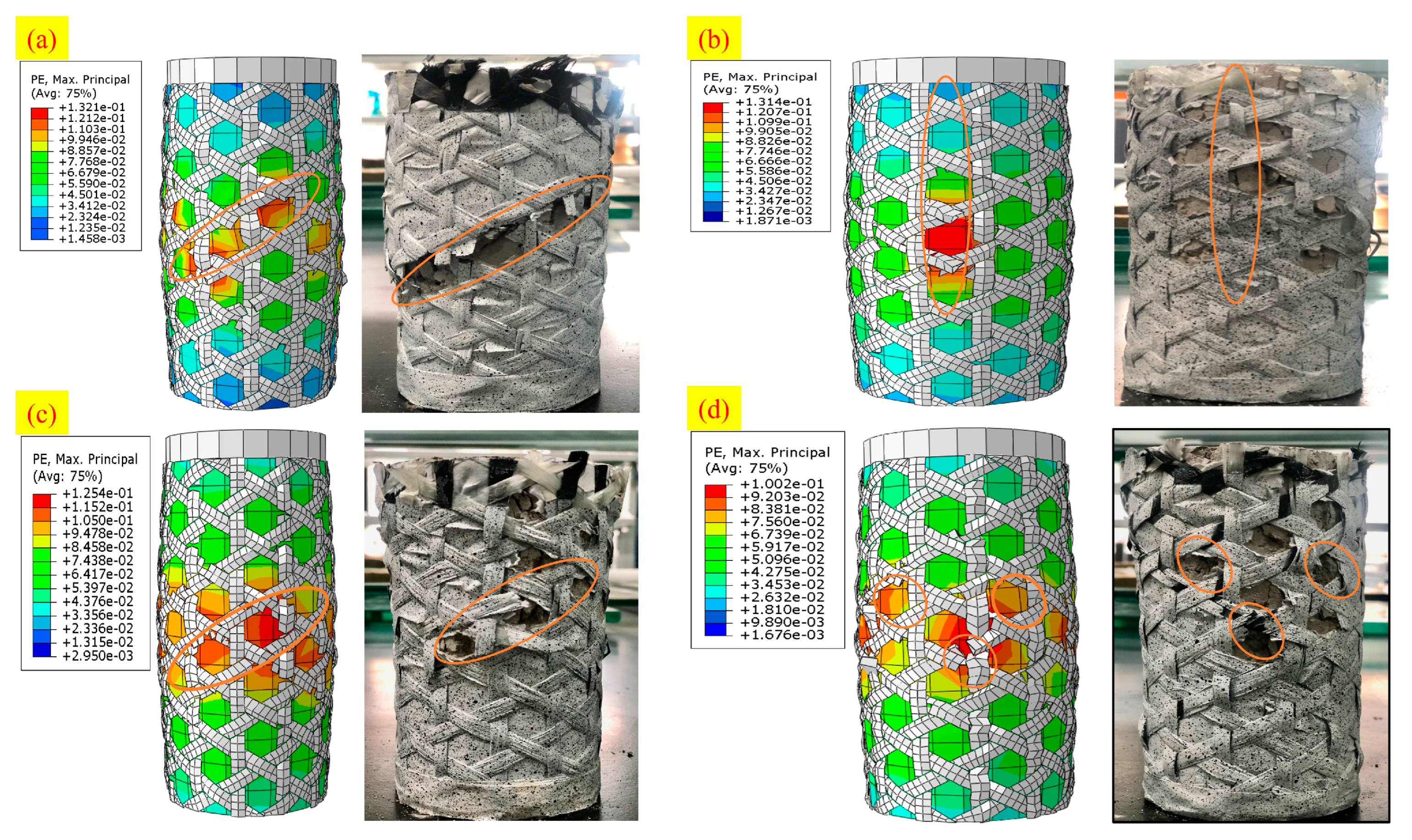
During the initial loading stages of the TWF-confined columns, a linear relationship was observed between the axial loading and strain. However, as the TWF reached its yield point, the axial loading increased linearly, marking the onset of the second linear segment in the stress–strain curve. Subsequently, the axial loading gradually approached the ultimate capacity of the members, leading to the rupture of TWF wraps and resulting in a rapid decline in axial capacity. The finite element simulations conducted on all four specimens indicated that each column exhibited a combined failure mode, involving both shear and crush failure, as illustrated in Figure 13. Fiber failure and maximum positive plastic strain (PE, principal) were utilized to visualize the crack patterns in the FEA models. This approach was chosen as the direction of cracks consistently aligns with the PE, principal in the concrete material, ensuring an accurate representation of the crack patterns [39].
The stress–strain curves obtained from experimental and finite element analysis (FEA) are presented in Figure 14. The numerical model exhibits higher accuracy in capturing the stress–strain performance of plain concrete columns confined with TWF tubes. However, some minor discrepancies can be observed in the numerical model. The FE model of specimen TWF-C exhibited a 1.20% decrease in compressive stress and a 10% increase in axial strain compared to the experimental measurements. For the FE model of TWF-G, there was a 3.44% increase in compressive stress and a 5% increase in axial strain relative to the experimental data. The FE model of TWF-CG2 demonstrated a 2.65% increase in axial compressive stress for columns. In the case of specimen TWF-GC2, the FE model exhibited a 3% increase in compressive stress and a 7.60% decrease in axial strain compared to the experimental measurements. These discrepancies can be attributed to minor inaccuracies resulting from variations in yarn fracture during weaving, uneven resin distribution, and gaps between yarn and resin [43] testing conditions, including boundary conditions, initial geometric imperfections, concrete and FRP material strength, manufacturing errors, the precision of testing instruments, and assumptions made in the FEA modelling [44].
Additionally, differences may arise from the definition of damage evolution parameters for the FRP material, and the friction coefficients assumed for the contact properties between the steel plate and concrete materials. Nevertheless, the FEA used model captures FRP-tube columns’ behavior to a reasonable extent.

5. Conclusions

The axial compression performance of Triaxial woven fabric confined concrete has been carried out in the present work. The axial stress and strain, failure morphology, and crack evolution of concrete columns confined by carbon fibers, glass fibers, and their hybrid TWF were analyzed. The finite element software, Abaqus, was employed to conduct nonlinear finite element analyses. Based on the observations, these conclusions have been made:
  • The stress–strain curve shape, compressive stress, and strain behavior of TWF-confined materials are affected by the fibers used in TWF warp and weft directions. The choice of fibers in these orientations affects the confinement mechanism and overall performance of the material under compressive loads. Fibers in the warp direction help increase the material’s resistance to lateral expansion, which affects compressive stress. Conversely, fibers in the weft direction help improve the material’s ability to withstand axial deformation, affecting compressive strain.
  • TWF-C confinement resulted in a significant enhancement of 118% in compressive stress. In contrast, TWF g confinement showed the most significant improvement, with a significant increase of 161% in axial strain. Furthermore, the mechanical properties of TWF samples with different fiber orientations exhibited variations. Specifically, the sample with glass fiber as weft and carbon fiber as warp (TWF-GC2) exhibited more significant improvement than the sample with glass fiber as warp and carbon fiber as weft (TWF-CG2). TWF-GC2 exhibited a 22.5% increase in compressive strength and an 8% increase in axial strain compared to TWF-CG2. The findings highlight the importance of considering specific arrangements of fiber orientations in TWF confinement to optimize concrete column performance.
  • The final failure morphology and crack evolution of each group of samples are different due to the different tensile and shear properties of different materials. Most of the samples with glass fiber as the weft show a “gradual crack” during the loading process, while the samples with carbon fiber as the weft show “instantaneous” damage.
  • The comparison between the finite element modelling results and experimental data confirms the accuracy of the proposed finite element approach for investigating the confinement processes in TWF confined columns. The successful replication of experimental fracture patterns using maximum positive primary plastic strains demonstrates the reliability and usefulness of the finite element method as a tool for studying complex confinement phenomena.

Author Contributions

Conceptualization, M.U.G. and H.Z.; methodology, M.U.G.; software, M.U.G.; validation, T.S. and K.G.A.; formal analysis, M.U.G.; investigation, M.U.G. and T.S.; resources, W.L.; data curation, N.A. and K.A.; writing—original draft preparation, M.U.G.; writing—review and editing, R.S. and K.A.; visualization, M.K.S.; supervision, W.L.; project administration, W.L.; funding acquisition, W.L. All authors have read and agreed to the published version of the manuscript.

Funding

This APC was funded by Donghua University.

Data Availability Statement

Not applicable.

Acknowledgments

This work was supported by the National Key Research and Development Program of China support by Ministry of Science and Technology (2022YFB3704504).

Conflicts of Interest

The authors declare no conflict of interest.

References

  1. Malla, P.; Khedmatgozar Dolati, S.S.; Ortiz, J.D.; Mehrabi, A.; Nanni, A. Damage and Defects in Fiber-Reinforced Polymer Reinforced and Strengthened Concrete Elements. J. Compos. Constr. 2023, 27, 04023035. [Google Scholar] [CrossRef]
  2. Sharma, E.M. Processing. Use Of Frp Sheets to Strengthen The Existing Beams. J. Data Acquis. Process. 2023, 38, 3481. [Google Scholar]
  3. Banaeipour, A.; Tavakkolizadeh, M.; Akbar, M.; Hussain, Z.; Ostrowski, K.A.; Bahadori, A.; Spyrka, M. Effects of Small Deviations in Fiber Orientation on Compressive Characteristics of Plain Concrete Cylinders Confined with FRP Laminates. Materials 2023, 16, 261. [Google Scholar] [CrossRef]
  4. Ghani, M.U.; Siddique, A.; Abraha, K.G.; Yao, L.; Li, W.; Khan, M.Q.; Kim, I.-S. Performance evaluation of jute/glass-fiber-reinforced Polybutylene Succinate (PBS) hybrid composites with different layering configurations. Materials 2022, 15, 1055. [Google Scholar] [CrossRef]
  5. Benny, B.; Bazli, M.; Rajabipour, A.; Arashpour, M. Durability of tubular sea water sea sand concrete and fibre-reinforced polymer hybrid structures: Mechanisms and effective parameters: Critical overview and discussion. Constr. Build. Mater. 2023, 366, 130206. [Google Scholar] [CrossRef]
  6. Zeng, J.-J.; Guo, Y.-C.; Gao, W.-Y.; Chen, W.-P.; Li, L.-J. Stress-strain behavior of concrete in circular concrete columns partially wrapped with FRP strips. Compos. Struct. 2018, 200, 810–828. [Google Scholar] [CrossRef]
  7. Li, G.; Maricherla, D.; Singh, K.; Pang, S.-S.; John, M. Effect of fiber orientation on the structural behavior of FRP wrapped concrete cylinders. Compos. Struct. 2006, 74, 475–483. [Google Scholar] [CrossRef]
  8. Pham, T.M.; Hadi, M.N.S.; Youssef, J. Optimized FRP Wrapping Schemes for Circular Concrete Columns under Axial Compression. J. Compos. Constr. 2015, 19, 04015015. [Google Scholar] [CrossRef]
  9. Zeng, J.-J.; Duan, Z.-J.; Guo, Y.-C.; Xie, Z.-H.; Li, L.-J. Novel fiber-reinforced polymer cross wrapping strengthening technique: A comparative study. Adv. Struct. Eng. 2019, 23, 979–996. [Google Scholar] [CrossRef]
  10. Sadeghian, P.; Rahai, A.R.; Ehsani, M.R. Effect of Fiber Orientation on Compressive Behavior of CFRP-confined Concrete Columns. J. Reinf. Plast. Compos. 2009, 29, 1335–1346. [Google Scholar] [CrossRef]
  11. Piekarczyk, J.; Piekarczyk, W.; Blazewicz, S. Compression strength of concrete cylinders reinforced with carbon fiber laminate. Constr. Build. Mater. 2011, 25, 2365–2369. [Google Scholar] [CrossRef]
  12. Fanaradelli, T.; Rousakis, T. Assessment of analytical stress and strain at peak and at ultimate conditions for fiber-reinforcement polymer-confined reinforced concrete columns of rectangular sections under axial cyclic loading. Struct. Concr. 2020, 22, 95–108. [Google Scholar] [CrossRef]
  13. Mohamed, H.; Masmoudi, R.; Chaallal, O. Compressive behaviour of filament winded GFRP tube-encased concrete columns. In Proceedings of the 4th International Conference on FRP Composites in Civil Engineering (CICE), Zurich, Switzerland, 22–24 July 2008. [Google Scholar]
  14. Hyer, M.W.; White, S.R. Stress Analysis of Fiber-Reinforced Composite Materials; DEStech Publications, Inc.: Lancaster, PA, USA, 2009. [Google Scholar]
  15. Fam, A.; Flisak, B.; Rizkalla, S. Experimental and analytical modeling of concrete-filled FRP tubes subjected to combined bending and axial loads. ACI Struct. J. 2003, 100, 499–509. [Google Scholar]
  16. Seffo, M.; Hamcho, M. Strength of Concrete Cylinder Confined by Composite Materials (CFRP). Energy Procedia 2012, 19, 276–285. [Google Scholar] [CrossRef]
  17. Ziaadiny, H.; Abbasnia, R. Unified cyclic stress-strain model for FRP-confined concrete circular, square and rectangular prisms. Struct. Concr. 2016, 17, 220–234. [Google Scholar] [CrossRef]
  18. Rao, Y.; Zhang, C.; Li, W. Structural analysis for triaxial woven fabric composites of carbon fiber. Compos. Struct. 2019, 219, 42–50. [Google Scholar] [CrossRef]
  19. El Messiry, M.; Eltahan, E. Stab resistance of triaxial woven fabrics for soft body armor. J. Ind. Text. 2016, 45, 1062–1082. [Google Scholar] [CrossRef]
  20. Zhou, H.; Xiao, X.; Qian, K.; Zhang, K.; Zhang, D. Numerical and experimental analyses of out-of-plane de-formation of triaxial woven fabric. Mater. Res. Express 2018, 5, 055305. [Google Scholar] [CrossRef]
  21. Fujita, A.; Hamada, H.; Maekawa, Z. Tensile Properties of Carbon Fiber Triaxial Woven Fabric Composites. J. Compos. Mater. 1993, 27, 1428–1442. [Google Scholar] [CrossRef]
  22. Dano, M.-L.; Gendron, G.; Picard, A. Mechanical behavior of a triaxial woven fabric composite. Mech. Compos. Mater. Struct. 2000, 7, 207–224. [Google Scholar] [CrossRef]
  23. Zhao, Q.; Hoa, S.; Ouellette, P. Progressive failure of triaxial woven fabric (TWF) composites with open holes. Compos. Struct. 2004, 65, 419–431. [Google Scholar] [CrossRef]
  24. Kueh, A.; Soykasap, O.; Pellegrino, S. Thermo-mechanical behaviour of singleply triaxial weave carbon fibre reinforced plastic. In Proceedings of the Spacecraft Structures, Materials and Mechanical Testing, Noordwijk, The Netherlands, 10–12 May 2005. [Google Scholar]
  25. Zhao, Q.; Hoa, S.V. Triaxial Woven Fabric (TWF) Composites with Open Holes (Part I): Finite Element Models for Analysis. J. Compos. Mater. 2003, 37, 763–789. [Google Scholar] [CrossRef]
  26. Zhao, Q.; Hoa, S.V.; Ouellette, P. Triaxial Woven Fabric (TWF) Composites with Open Holes (Part II): Verification of the Finite Element Models. J. Compos. Mater. 2003, 37, 849–873. [Google Scholar] [CrossRef]
  27. Díaz Valdés, S.H.; Soutis, C. Real-time nondestructive evaluation of fiber composite laminates using low-frequency Lamb waves. J. Acoust. Soc. Am. 2002, 111, 2026–2033. [Google Scholar] [CrossRef]
  28. Shi, Y.; Swait, T.; Soutis, C. Modelling damage evolution in composite laminates subjected to low velocity impact. Compos. Struct. 2012, 94, 2902–2913. [Google Scholar] [CrossRef]
  29. Anderson, T.L. Fracture Mechanics: Fundamentals and Applications; CRC Press: Boca Raton, FL, USA, 2017. [Google Scholar]
  30. Ansys, I.J.A.R. Engineering data, composite materials library. ANSYS Release 2017, 18, 1. [Google Scholar]
  31. Hashin, Z.; Rotem, A. A Fatigue Failure Criterion for Fiber Reinforced Materials. J. Compos. Mater. 1973, 7, 448–464. [Google Scholar] [CrossRef]
  32. Barbero, E.; Cosso, F.; Roman, R.; Weadon, T. Determination of material parameters for Abaqus progressive damage analysis of E-glass epoxy laminates. Compos. Part B Eng. 2012, 46, 211–220. [Google Scholar] [CrossRef]
  33. Rahimian Koloor, S.S.; Karimzadeh, A.; Yidris, N.; Petrů, M.; Ayatollahi, M.R.; Tamin, M.N. An Energy-Based Concept for Yielding of Multidirectional FRP Composite Structures Using a Mesoscale Lamina Damage Model. Polymers 2020, 12, 157. [Google Scholar] [CrossRef]
  34. Ferrotto, M.; Fischer, O.; Cavaleri, L. A strategy for the finite element modeling of FRP-confined concrete columns subjected to preload. Eng. Struct. 2018, 173, 1054–1067. [Google Scholar] [CrossRef]
  35. Popovics, S. A numerical approach to the complete stress-strain curve of concrete. Cem. Concr. Res. 1973, 3, 583–599. [Google Scholar] [CrossRef]
  36. Mander, J.B.; Priestley, M.J.N.; Park, R. Theoretical Stress-Strain Model for Confined Concrete. J. Struct. Eng. 1988, 114, 1804–1826. [Google Scholar] [CrossRef]
  37. Nayal, R.; Rasheed, H.A. Tension stiffening model for concrete beams reinforced with steel and FRP bars. J. Mater. Civ. Eng. 2006, 18, 831–841. [Google Scholar] [CrossRef]
  38. Wahalathantri, B.; Thambiratnam, D.; Chan, T.; Fawzia, S. A material model for flexural crack simulation in reinforced concrete elements using ABAQUS. In Proceedings of the First International Conference on Engineering, Designing and Developing the Built Environment for Sustainable Wellbeing, Kochi, India, 22–24 July 2011; pp. 260–264. [Google Scholar]
  39. Genikomsou, A.S.; Polak, M.A. Finite element analysis of punching shear of concrete slabs using damaged plasticity model in ABAQUS. Eng. Struct. 2015, 98, 38–48. [Google Scholar] [CrossRef]
  40. Ellobody, E.; Young, B.; Lam, D. Behaviour of normal and high strength concrete-filled compact steel tube circular stub columns. J. Constr. Steel Res. 2006, 62, 706–715. [Google Scholar] [CrossRef]
  41. Ghernouti, Y.; Rabehi, B. Effectiveness of Hybrid and Partially Confined Concrete Subjected to Axial Compressive Loading Using CFRP and GFRP Composite Materials. Slovak J. Civ. Eng. 2020, 28, 8–14. [Google Scholar] [CrossRef]
  42. Karouche, A.; Hebbache, K.; Belebchouche, C.; Lahbari, N.; Kessal, O.; Czarnecki, S. External Confined Concrete Cylinders Behavior under Axial Compression Using CFRP Wrapping. Materials 2022, 15, 8232. [Google Scholar] [CrossRef]
  43. Zheng, L.; Xiao, Y.; Liu, L.; Xu, F. Experimental and numerical study of the behavior of epoxy foam-filled 3D woven spacer composites under bending load. Polym. Compos. 2022, 43, 3057–3067. [Google Scholar] [CrossRef]
  44. Raza, A.; Ahmad, A. Numerical investigation of load-carrying capacity of GFRP-reinforced rectangular concrete members using CDP model in ABAQUS. Adv. Civ. Eng. 2019, 2019, 1745341. [Google Scholar] [CrossRef]
Figure 1. Triaxial woven fabric.
Jcs 07 00358 g001
Figure 2. Triaxial woven fabric confined concrete columns.
Jcs 07 00358 g002
Figure 3. 3D model of Triaxial woven fabric.
Jcs 07 00358 g003
Figure 4. Concrete stress–strain behavior under confinement. ( f c o = 14.6 , c o = 0.01 , c * = 0.015 ).
Jcs 07 00358 g004
Figure 5. Tension stiffening model.
Jcs 07 00358 g005
Figure 6. Stress–strain behavior of different groups.
Jcs 07 00358 g006
Figure 7. Control specimen failure.
Jcs 07 00358 g007
Figure 8. Failure of confined specimens (a) TWF-C, (b) TWF-G, (c) TWG-CG2, (d)TWF-GC2.
Jcs 07 00358 g008
Figure 9. Crack propagation in TWF-C (Circle indicates crack growth with time interval).
Jcs 07 00358 g009
Figure 10. Crack propagation in TWF-G (Circle indicates crack growth with time interval).
Jcs 07 00358 g010
Figure 11. Crack propagation in TWF-CG2 (Circle indicates crack growth with time interval).
Jcs 07 00358 g011
Figure 12. Crack propagation in TWF-GC2 (Circle indicates crack growth with time interval).
Jcs 07 00358 g012
Figure 13. Comparison of experimental and simulated results (a) TWF-C, (b) TWF-G, (c) TWF-CG2, (d) TWF-GC2.
Jcs 07 00358 g013
Figure 14. Comparison of stress–strain curves of experimental and FEA results.
Jcs 07 00358 g014
Table 1. Parameters of epoxy resin.
Density
Swancor 2511-1ASwancor 2511-1BSTensile strength (MPa)Tensile modulus (MPa)Extensibility (%)Flexural strength (MPa)Flexural modulus (MPa)
1.1–1.20.9–1.067–802700–35004.5–8.5110–1402800–3600
Table 2. Engineering Constants Values of carbon and glass [30].
MaterialsE11 GPaE22 GPaE33 GPaNu12Nu13Nu23G12 GPaG13 GPaG23 GPa
Carbon10510.010.00.320.320.443.33.33.6
Glass40.08.408.400.3150.3150.394.34.33.2
Table 3. Hashin damage parameters [33].
PropertyParameterTWF-CTWF-G
Strength propertiesTensile strength in the normal direction (MPa)1340820
Compressive strength in the normal direction (MPa)1192500
Tensile strength in transverse dir. of fiber (MPa)19.680.6
Compressive strength in transverse dir. of fiber (MPa)92.3322
Shear strength in the normal direction of fiber (MPa)5154.5
Shear strength in transverse dir. of fiber (MPa)23161.2
Damage propertiesFracture tensile energy in fibers’ dir. (mJ/mm2)48.432
Fracture tensile energy in transverse dir. (mJ/mm2)60.320
Fracture compressive energy in fibers’ dir. (mJ/mm2)4.54.5
Fracture compressive energy in transverse dir. (mJ/mm2)8.54.5
Table 4. Elastic and Plastic properties of the CDP model.
Elastic Properties
Young’s modulus (MPa)19039
Poisson’s ratio0.2
Plastic Properties
Dilation angle (degree)30
Eccentricity0.1
fb′/fco′1.16
Kc0.667
Table 5. Experimental results of different groups.
Specimenfco (MPa)/fcc (MPa)εco/εcc
ControlMean14.60.011
Upper CI16.650.012
Lower CI12.650.010
TWF-CMean32.000.023
Upper CI33.870.028
Lower CI30.210.018
TWF-GMean24.730.030
Upper CI26.430.034
Lower CI22.960.026
TWF-CG2)Mean25.000.025
Upper CI25.780.030
Lower CI23.980.020
TWF-GC2Mean30.000.027
Upper CI31.860.031
Lower CI28.130.024
Disclaimer/Publisher’s Note: The statements, opinions and data contained in all publications are solely those of the individual author(s) and contributor(s) and not of MDPI and/or the editor(s). MDPI and/or the editor(s) disclaim responsibility for any injury to people or property resulting from any ideas, methods, instructions or products referred to in the content.