Highlights
- The effects of the punch nose radius on the drawing force, forming energy, cup surface roughness, cup thickness, and cup height were studied.
- Drawing force decreases as the punch nose radius increases at the zero blank holder angle.
- The drawing force of the hybrid MMC’s punch nose is less than that of the steel DIN 1006-02 by 5%.
- The difference in the dimensionless deflection of the Rayleigh and ANSYS models increases when the power law index increases in the C-F FG beam, while the difference decreases with the increasing power law index in the F-C FG beam.
- The cup thicknesses are low above the punch nose radius, reaching the minimum value at location 5, and high at the flange area for all the punch nose radius and punch materials.
- Cup thickness increases as the punch nose radius increases, and the thickness values that are formed by the MMCs at all locations (six locations) are high compared with those formed via the steel DIN 1006-02 punch.
- The effect of the punch nose radius on the cup height is the same as the effects on cup thickness with the same advantages of the hybrid MMCs over steel DIN 1006-02 punch nose materials.
- The tendency of cup height varies with respect to the punch nose radius in the MMCs and the steel’s punch nose.
Abstract
Composites have many uses in industrial applications. A new trend, the deep drawing process, is to use these composite materials to obtain drawn products with high quality. This study investigated the effect of using a hybrid composite material in the deep drawing process. The main aim was to perform the deep drawing process with cups using the punches of the iron-based hybrid metal matrix composites (MMCs) reinforced with a 3% volume fraction of constant mix (20% ZrO2 and 80% Al2O3) by means of powder metallurgy. After realizing the best hybrid metal matrix composites (MMCs) from a set of five samples that can be used to manufacture a punch nose, the effects of the punch nose radius on the drawing force, forming energy, cup surface roughness, cup thickness, and cup height were evaluated and compared with those of steel. The results indicate that the drawing force decreases as the punch nose radius increases at the zero blank holder angle (BHA). The drawing force of the hybrid MMC’s punch nose is less than that of the steel DIN 1006-02 by 5% as a result of the radius of the punch nose effects. Therefore, the forming energy is decreased when the punch nose radius increases, and the lowest energy is obtained when the punch nose radius is 12 mm and BHA = 4°. The effect of the radius of the punch nose on cup height is the same as the effects on cup thickness, with the same advantages of the hybrid MMCs over DIN 1006-02 steel punch nose materials.
1. Introduction
Deep drawing is one of the widely used metal forming processes. It is utilized to shape any blank (piece of metal sheet) into an axisymmetric 3D component with measurable draw depth. In this procedure, blank or sheet metal takes the shape of the used die due to the force applied by the punch [1].
Five associated activities are contained via the deep drawing process: sliding and stretching over the punch face, bending and sliding over the punch profile radius, stretching between the punch and the die, sliding and bending over the die profile, and pure radial drawing between the die and the blank holder [2].
Some defects in a drawn product can occur, such as tearing, wrinkling, earing, and surface scratches. For example, the process of a crack occurring near or in the base of the cup is called tearing, and this occurs due to the high tensile stresses generated, and then the failure and thinning of the metal at the position of crack initiation. The wrinkling of the cup wall and flange includes waviness or the ups and downs that are created at the flange. The flange is retained in the region of the cup wall when the cup is drawn into the die hole. Earing is the creation of ears (irregularities) at the upper edge of a deep drawn cup due to anisotropy of the sheet metal. If the material is perfectly isotropic, the ears do not form. A surface scratch is a result of using poor lubrication, dies, or a rough punch that causes scratches in a drawn cup. These defects can be reduced by controlling some parameters that affect the deep drawing process, and these parameters are the material properties of sheet thickness, punch force, sheet metal, blank holding force (BHF), and punch velocity [3]. Specifically, these parameters can be divided as follows [4]:
- Process parameters (such as the drawing ratio, material properties, coefficient of friction, and blank holder force (BHF)).
- Geometrical parameters (such as the corner radius of the cup, cup diameter, and blank thickness).
- Machine parameters (such as the die and punch radius).
According to these defects in the deep drawing process, several researchers studied the impacts of these parameters on the process of deep drawing and the quality of its products [2].
Reddy et al. [2] experimentally studied the influences of the main three affected parameters of the deep drawing process of the AA6111 aluminum alloy, and these parameters were the blank holder force, die radius, and punch nose radius. They found that the influence percentage of the punch nose radius and the blank holder force was 30.12% and 56.98%, respectively. Also, the die radius had the least effect.
Trivedi Nirav [3] investigated the influences of the deep drawing parameters on 3D shape sheet metal that progressively formed via the mechanical action of a die and punch to decrease the various defects that can occur in a drawn product. Reduced velocity of the punch, sheet thickness, blank holding force, production cost, and punch force are effective parameters to regulate defects like fracture defects, earing, tearing, and wrinkling in the deep drawing process. The experimental work was carried out using a universal testing machine to estimate the load, displacement, strain, and stress.
Chen et al. [5] studied the deep drawing of a square cup and focused on the influence of the punch radius, forming temperature, and radius of the die corner and also on the magnesium alloy sheet (AZ31) formability. They found that uniform material flow occurs, as well as the occurrence of fracture delays when a larger radius of the punch is used. Also, they noted an enhancement of formability due to the increment of the radius of the die profile up to an optimum value.
Jawad [6] applied the finite element technique using ANSYS software version 5.4 for the simulation of the deep drawing of a cylindrical cup of annealed mild steel with a carbon percentage of 0.15%. The author studied the impacts of the punch shoulder radius on the variation in thickness over a drawn cup wall, punch load, and interface contact state between the punch and blank sheet. The results showed that the punch load decreases slightly due to an increment of the punch radius and vice versa.
Raju et al. [7] investigated the impact of the die corner radii, blank holder force, and punch nose radii on aluminum AA6061 cup wall thickness. The thickness of the cup wall from the center of the cup to the flange edge at different points of the sectioned drawn cups was measured. They found that the material is drawn easily via the die cavity by increasing the radius of the die shoulder.
Djavanroodi et al. [8] used novel hydro-forming tools of deep drawing for aluminum alloy AA6061-T6. They established a decrease in the initial pressure and punch force due to an increment of the radius of the punch nose.
Gowtham et al. [9] evaluated the influence of the punch nose radius in deep drawing on the formability of the aluminum alloy (6061), assuming that the radius of the punch nose, coefficient of friction, and thickness of the blank sheet are constant. They simulated the deep drawing process by applying the FEM using DEFORM-3D software (Columbus, Ohio, USA). Their results showed that the drawing force increases when the die shoulder radius decreases. The die shoulder radius decrement led to an increment of the drawing force and resulted in marks of stretching and earing with the drawn part.
Reddy et al. [10] studied the relation between the wrinkling of cylindrical parts and the effect of several factors like the coefficient of friction, die edge radius, punch radius, and blank holder force (BHF) in the deep drawing of carbon steel. They found that reducing the deep-drawing depth, increasing the tools’ edge radius, decreasing friction, and increasing the blank holding force all together in one operation would reduce the height of the wrinkles.
Raju et al. [11] used the software (DEFORM-2D, Columbus, Ohio, USA) to investigate the deep drawing process formability of aluminum AA6061 while considering several parameters, such as the punch diameter, punch nose radius, and blank thickness. They concluded that when the punch nose radius increases, the damage factor reduces and the height increases.
Purushotham [12] studied the effect of the holding and friction forces of the stress distributions and models of radial and hoop strain during copper and mild steel deep drawing. The results showed that the radial strain and thinning at the punch profile zone increase when the blank holder force increases. However, the thickness decreases at the cup rim. Also, the author noted that when the friction coefficient increases, the strain values increase too.
Dilmec et al. [13] used AA2024-T4 aluminum alloy sheets according to the ISO 12004-2 standard [14] to investigate the effect of sheet thickness on thickness distribution and anisotropy at room temperature. They observed that there are no significant differences between various thicknesses of 0.8, 1, and 2 mm and directions on the anisotropy.
Chiorescu et al. [15] analytically verified the influences of the relative connection radius and connected the portion angle for the drawing plate on the drawing force. They analyzed the surface thickness distribution of the work piece to show the cylindrical deep drawing quality due to the contribution of the drawing plate radius. They found that the results are useful in the experimental trial for judicious program elaboration.
Zein et al. [16] studied the effect of the blank thickness and punch nose radius on the thinning of a mild steel sheet. They noted that the initial blank thickness is proportional to the average distribution of the drawn blank thickness and thinning is stable when the punch nose radii are greater than three times that of the blank thickness.
Younis [17] used a fixed blank holder gap (BHG) and the variable force of the blank holder (BHF) to fix the metal sheets via the deep drawing of low carbon steel cylindrical cups and to study the wall thickness change in the drawn cup. The author noted that it is unattainable to use a too large blank holder gap (BHG) because of excessive wrinkling at the straight sides, which causes tearing, and when the blank holder gap (BHG) increases, more material flows into the die cavity. Also, it has been concluded that the optimum drawing test happens when the blank thickness is equal to the blank holder gap (BHG).
Alin et al. [18] investigated the effect of the blank holder force, punch radius, and die radius on wrinkling growth using ABAQUS 3D software (Providence, RI, USA). They noted that the die radius has a significant effect on the wrinkling defects at the friction coefficient = 0.01, and the blank holder force caused less effects on the deep drawing process.
El Sherbiny et al. [19] built a model by using a (3-D) finite element approach to simulate the process of deep drawing for a mild steel sheet with simplified boundary conditions and anisotropic properties. They compared the experimental result with the simulation results to check the validation of the finite element model. They found that the die shoulder radius should be about 10 times the blank thickness and the punch profile radius should be greater than four times the sheet thickness. Thus, the holding force of the blank must not exceed 3 tons to avoid the increment of the excessive thinning and residual stresses.
Shah et al. [20] investigated the influence of the most critical deep drawing parameters that lead to defects and thinning through the blanks using experimental and statistical methods. They calculated the percentage contribution for the individual parameters by using the ANOVA analysis technique. They found that the contribution percentages of the die radius, blank holding force, and punch nose radius are 36.44%, 53.39%, and 8.48%, respectively.
Singh and Agnihotri [21] investigated the influences of deep drawing factors (the materials properties, blank holder pressure, die radius, frictional coefficient, and punch radius) on the quality and defects of automotive parts. These product requirements caused an increase in the failure defects’ tendency and challenge process with minimum defects in the produced product.
Namer et al. [22] utilized FEM by using DEFORM-2D software to simulate the deep drawing process of a cylindrical cup and studied the effect of the punch nose radius on the drawing force, thickness distribution, and maximum drawing height. They compared the simulation and experimental results to check the accuracy of the finite element models. They concluded an enhancement of the sheet formability when the punch nose radius increases.
Al-Hamdani [23] used ANSYS software version 11.0 to assess the influence of the punch profile radius on the value of the spring back induced in the height of the drawn cup and drawing force, cup wall thickness, strain distributions over the cup wall, and the contact regions between the blank, punch, and drawn cup in the deep drawing process. They compared the numerical results against the experimental results to check the accuracy of the finite element model. They found an increase in the length of the contact distance between the blank and the punch due to an increment of the punch corner radius, and its value is approximately equal to the punch corner radius. Also, the strain distributions for all punches chosen are similar in shape and have the same trends. Then, the authors noted that the greatest thinning occurs with the hemispherical punch is Rp = 26 mm. Finally, the spring backs’ percentage and the cup height have been increased due to an increment of the punch profile radius.
Khazaal et al. [24] prepared the hybrid iron-based metal matrix composites (MMCs) reinforced with a 0, 1, 2, 3, and 4% volume fraction of constant mix (80% Al2O3 and 20% ZrO2) via powder metallurgy and examined their mechanical properties. The results showed that the composites have 61%, 37%, and 7% higher compression strength, hardness HRC, and radial crushing strength than the matrix at (97% Fe + 3% volume fraction of (80% Al2O3 + 20% ZrO2).
Composite materials offer good mechanical, thermal, electrical, and wear qualities, making them acceptable for a number of applications. Due to their low cost and isotropic qualities, particle-reinforced composites are popular. Metal matrix composites with ceramic particles in a high-strength matrix alloy are interesting for multifunctional electronic packaging, optical system mirror substrates and support structures, and inertial guidance components [25,26].
This study intends to investigate the effect of using the hybrid composite material in the deep drawing process. The main aim was to perform the deep drawing process of cups by using the punch of the iron-based hybrid metal matrix composites (MMC’s) reinforced with a 3% volume fraction of constant mix (20% ZrO2 and 80% Al2O3) by means of powder metallurgy. After realizing the best hybrid metal matrix composites (MMC’s) from a set of five samples that can be used to manufacture the punch nose, the effects of the punch nose radius on the drawing force, forming energy, cup surface roughness, cup thickness, and cup height will be evaluated and compared against that made by steel. The main application of this work is the deep drawing of the AA2024-T4 sheet used in the manufacture of some parts of aircraft, automotive, and industrial parts with a hybrid metal matrix composite punch.
2. Material
Composite materials are widely used compared to other conventional structural materials because they offer superior mechanical, thermal, and tribological properties in addition to its low weight and flexible design [27,28,29]. In this research, an 80% volume fraction of alumina Al2O3 and a 20% volume fraction of zirconium ZrO2 are mixed together and used as a reinforced material. The synthesized reinforced material with a 3% volume fraction is used to produce hybrid iron-based metal matrix composites using the powder metallurgy technique. Powder metallurgy is a multi-step fabrication process that includes the following steps:
- Mixing was carried out without a ball to prevent the agglomeration of the powder mixture due to the heat caused by the collisions of the ball mill, and to avoid the problem of agglomeration caused by static charge. Wet mixing was afforded by using the polar solvent n-butanol at about (2–3) wt.% of the composite,
- Compacting: The 250 ton hydraulic press was used. In powder compaction, metal powder was compacted in a die at a high pressure (650 Mpa), room temperature, and using a hydraulic press for 30 min. The die forms the hollow bottom and was held vertically,
- Sintering: Samples were sintered at 1120 °C for 30 min. The furnace (VS2 FURNACE /MI/Metals Research Limited Cambridge, Cambridge, UK) was heated at 5 °C/min under pure argon at 10 L/min. These reinforced materials were used to enhance the tribological properties of iron-based metal matrix composites that used a punch in this work. Also, the sheet of AA2024-T4 with a different thickness was drawn to form cylindrical cups.
In our previous work [24], the best mechanical properties were obtained at (97% Fe + 3% volume fraction of (80% Al2O3 + 20% ZrO2)) among all reinforcement volume fractions. The synthesized composite had advanced higher properties of compression strength, hardness HRC, and radial crushing strength of 61%, 37%, and 7%, respectively, compared to the matrix properties. Table 1 demonstrates the volume fraction of the hybrid metal matrix composites’ iron.

3. Deep Drawing Die Design and Manufacturing
3.1. Die Design Stage
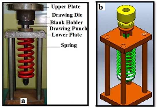
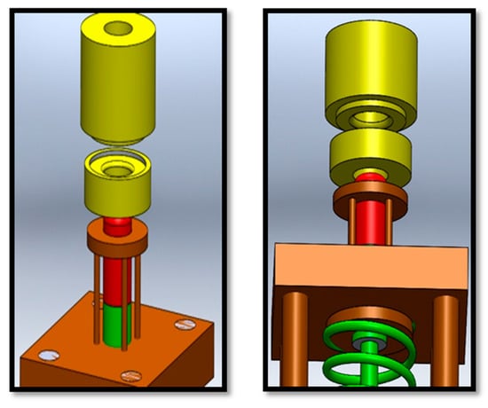
Deep drawing was used to manufacture several parts in aerospace and automobiles [30,31,32]. To produce cups with a flange, a reverse deep drawing die was designed and manufactured, as explained in Figure 1 and Figure 2. Figure 1 shows the deep drawing die that consists of six main parts, as follows: spring, blank holder, lower plate, drawing punch, drawing die and upper plate. Figure 2 shows a schematic diagram of the die of the deep drawing process.
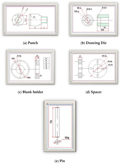
To design the deep drawing die, several parameters must be chosen or calculated to obtain the dimensions of the six main parts of the deep drawing die. The first main parameter is the punch nose radius (Rp). Rp depends on the thickness of the sheet metal and equals 4–10 times of the thickness of the sheet metal [29]. In this research, the values of Rp are 5, 7, 9.5, and 12 mm. The second main parameter is the blank holder angles and its values are 0°, 1°, 2°, 3°, and 4°. The clearance can define the gap between the punch and the die, [1] and its value is 1.4 mm. The value of the cup diameter (dc) (which equals to punch diameter) can be calculated as follows:
where is the percentage of reduction, is the inner diameter of the drawn cup, and it is equal to the punch diameter (40 mm). is the blank diameter.
The radius of the die corner is chosen to be 6.5 mm. However, the diameter of the die is calculated using Equation (2) and its value is 42.8 mm, as shown below:
The drawing force is the most important parameter in the deep drawing process and can be calculated using Equation (3)
where is the die diameter, is the thickness of the sheet metal, and is the yield strength of the blank material, as 1, 7, and 30, respectively [14,15,16]. is the blank diameter, is the punch diameter, and is the drawing force constant (which ranges between 0.52 and 0.7).
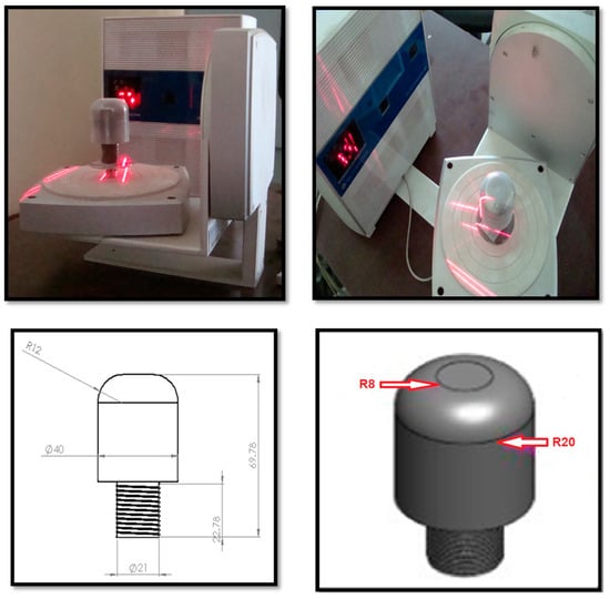
The dimensions of the six main parts for the deep drawing die are illustrated in Figure 3.
3.2. Heat Treatment of the Active Die Parts
Heat treatment was performed by heating the material and then cooling in water, oil, and brine. To increase the hardness of the parts of the die, the parts were heated to the upper critical point temperature for hypo-eutectoid steels to 30–50 °C and then quenched. This heat treatment is denoted as the quenching process. Then, tempering heat treatment was applied to relieve the residual stresses in the work peace.
3.3. Deep Drawing of Circular Cup
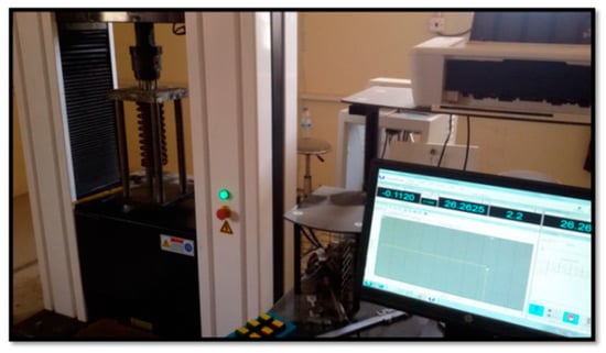
First, the die was put in universal testing machines (UTM) to obtain the deep drawing process, as pictured in Figure 4. Afterwards, the blank was placed on the die surface. The next step was to draw the blank by holding it with a certain value of force using the blank holder and moving the punch. After forming the cup, the punch returned to its initial position.
4. Tests
4.1. Thickness Distribution Test
4.2. Surface Roughness Test
The interaction of the real object with its environment was determined via the surface roughness due to its important role. Usually, rough surfaces have higher coefficients of friction than smooth surfaces and wear very quickly. Therefore, the value of a high roughness is often difficult to control through manufacturing, which is expensive and undesirable. The decrement in the surface roughness usually leads to an increase in its manufacturing costs. The roughness measuring device (Pocket Surf III) was used to measure the average cups’ surface roughness (Ra), as shown in Figure 10. It is a portable surface roughness measuring instrument, and it is likely designed to comply with various surface roughness measurement standards ISO 4287 [33]. Three times each thickness was measured and the average of these measurements was considered. The test steps are as follows;

- Contact probe: The Pocket Surf III contains a diamond-tipped contact probe. Carefully place this stylus on the surface to be measured,
- Track the surface: When turned on, the stylus moves across the surface. It follows the peaks and valleys of the surface,
- Data acquisition: The stylus records the vertical displacement of the surface and records the height differences over the measured length,
- Roughness parameters: After data acquisition, the instrument determines the roughness parameters such as Ra (average roughness) and Rz, Rq, Rmax, etc., according to the standards used.
4.3. Punch Profile Test
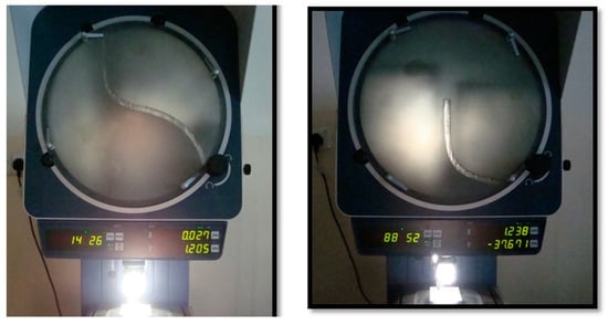
The punch profile was measured via the coordinate’s measurement machine using 3D laser scanner HD (Next Engine 3D scanner, Northfield, MN, USA), as shown in Figure 11.
5. Results
In this section, the required drawing force is affected by the punch nose radius. A comparative study was made between the punch noses that are made from the best mix of iron-based MMC’s on the PM and the ordinary punch made of steel DIN 1006-02. Generally, all measurements in this study were made for three different samples, and the average value was considered.
5.1. Drawing Force
The maximum drawing force is equal to 74,000 N and was calculated using Equation (3). Experimentally, the drawing force was measured from the universal testing machines (UTM) with different values according to the values of the punch nose radius (Rp) when the blank holder angle (φ) is zero. Figure 12 compares the steel DIN 1006-02 punch nose radius obtained from an earlier study [22] with the hybrid metal matrix composite punch nose radius, which affects the drawing force.
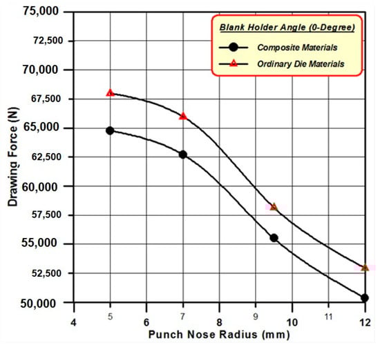
Figure 12.
Punch nose radius effect on drawing force by the MMC’s and the (DIN EN 1006-2) steel punch nose.
The results show that the maximum drawing forces by the metal matrix composite punch nose have the same tendency of the steel punch as shown in the mathematical expression of Equations (4) and (5), respectively. Both these equations have a higher correlation coefficient equal to one with a standard deviation equal to zero. The maximum drawing forces from the composite punch nose are less than the drawing force by the steel punch nose with an average approximate difference of 3000 N, and that is clearly shown in Figure 12.
These results are in agreement with Faramarz et al. [9] that showed a decrement of the punch force and a decrement of the initial chamber pressure due to an increment of the punch radius. RAJU [8] explained that the minimum punch nose radius leads to the restriction of material flow from the cup bottom to the side wall because it needs a high drawing force. Özek et al. [30] showed that the metal flows easily due to an increment of the punch radius; then, the drawing force decreases.
5.2. Forming Energy
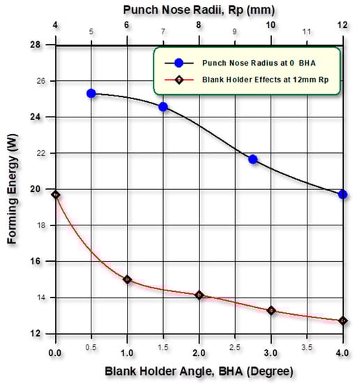
The required formation energy was computed via the applied work to form the cups and the time of forming. The work was based on the load–deflection curve to form the cup. Figure 13 illustrates the applied forming energy in both the punch nose radius and the blank holder angle. The lowest energy occurs at a 12 mm punch nose radius and a 4o blank holder angle (BHA). This is clearly true according to the effect of an increment of the punch nose radius, which decreases the forming load. The same behavior is expected to occur as a result of increasing the blank holder angle (BHA).
5.3. Cup Surface Roughness
The relationship between the punch nose radius (Rp) and the surface roughness (Ra) of the cup is explained in Figure 14. The punch nose radius (Rp) increases up to 9.5 mm when the surface roughness (Ra) reduces. With standard deviation equal to zero and the correlation coefficient equal to one, the rational Equations (6) and (7) describe the increment of roughness (Ra) at the punch nose radius as Rp = 12 mm with a value of 0.69 μm.
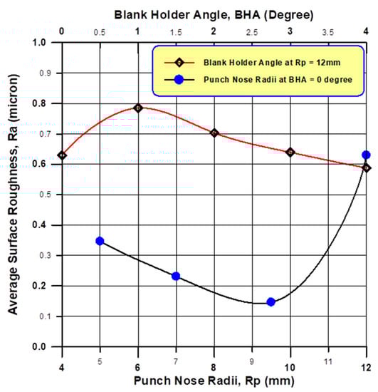
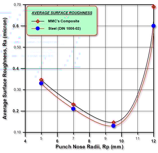
Figure 14.
Relationship between punch nose radius, blank holder force, and average surface roughness.
There is a very close behavior of the average surface roughness versus the punch nose radius for the MMC’s and the steel DIN 1006-02 punch nose, as expressed in rational Equations (7) and (8), respectively. The roughness initially decreases as the punch nose radius increases from 5 mm to reach its minimum roughness at 9.5 mm, and then increases due to an increment of the punch nose radius, as represented in Figure 15.
5.4. Cup Thickness
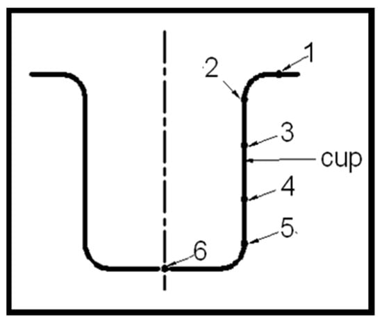
The effects of the blank holder and the punch nose radius on the changes in cup thickness, which are measured at six points on the cup, are explored in the section. The comparison between the two types of punch nose materials is also discussed.
The punch nose radius affects the thinning and the thickness distribution for the cup when the blank holder angle (BHA) is zero degree. Generally, the values of thickness are high at the flange area and lower than the punch nose radius. The difference in thickness reduced between the thickening and thinning locations of the cup is the better forming objective.
Figure 16 compares the steel and hybrid MMC’s thickness distribution at six points for a 5 mm punch nose radius. The thickness at the cup flange zone (i.e., location 1) (explained in Figure 16) is 1.2 mm for both the punch nose materials (i.e., no thickness reduction). Then, the thickness decreases and reaches its minimum value at location 5 above the zone of the punch nose radius with thickness value of 0.97 mm and 1.02 mm for the steel and the MMC’s punch nose materials, respectively. Bending under tensile stresses causes a decrease in thickness in the radial direction (thinning) that takes place during the drawing process. The thickness distribution curve by the MMC’s punch nose materials (Figure 16) is higher than the steel punch with an average difference of 0.2347 mm after the flange zone (location 1).
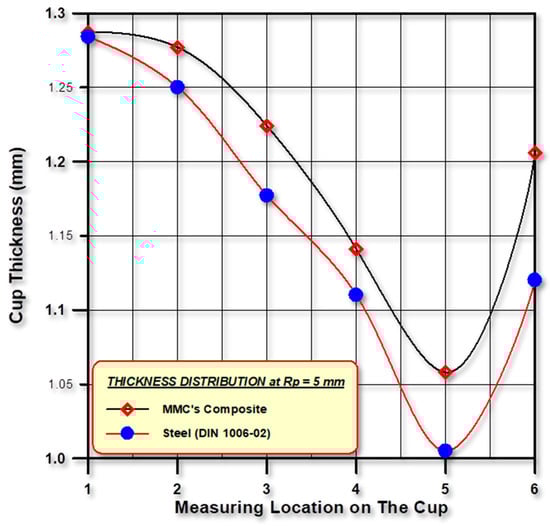
Figure 16.
Punch nose materials’ effect on cup thickness distribution that was measured at different points along the cup for 5 mm punch nose radius (Rp).
Figure 17 displays the distribution of thickness when the nose radius is 7 mm, and it is clear that the increase in the cup thickness at location 1 and their values are 1.234 mm and 1.237 mm for the steel and the MMC’s punch nose materials, respectively. Radial drawing occurs via a circumferential compressive stress in the flange zone region where the materials become thicker because of compressive stress. The thickness of the cup reduces toward the punch nose radius zone and reaches its minimum value of 0.98 mm and 1.032 mm at the cup (location 5) for the steel and the MMC’s punch nose materials, respectively. The thickness distribution curve for the MMC’s punch nose materials, as shown in Figure 16, is higher than that of the steel punch with an average difference of 0.2348 mm after the flange zone (location 1).
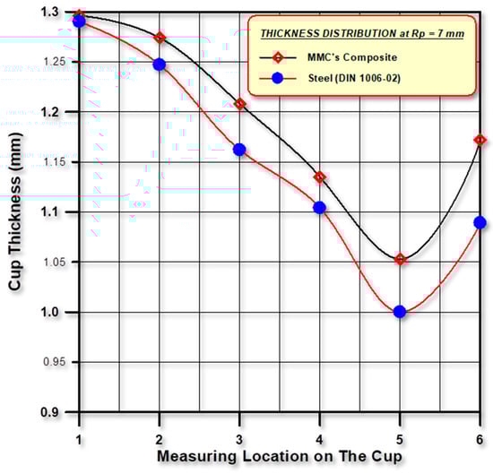
Figure 17.
Effect of punch nose materials on cup thickness distribution that was measured at different points along the cup for 7 mm punch nose radius (Rp).
Figure 18 and Figure 19 show the thickness distribution when the punch radii (Rp) are 9.5 and 12 mm, respectively. In Figure 18 and at location 1, the value of thickness is 1.259 and 1.262 mm for the steel and the MMC’s punch nose materials, respectively. However, at location 5, the thickness of the cup is approximately 1 mm for both the steel and the MMC’s. Maximum thickening values are 1.287 and 1.284 mm for the steel and the MMC’s punch nose materials at location 1 for the 12 mm nose radius, as shown in Figure 19. The thickness distribution curve by the MMC’s punch nose materials (Figure 18 and Figure 19) is higher than the steel punch with an average difference of 0.24 mm and 0.244 mm after the flange zone (location 1) for a 9.5 mm and 12 mm punch nose radius, respectively.
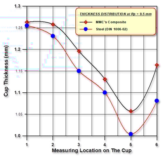
Figure 18.
Influence of punch nose materials on cup thickness distribution that was measured at different points along the cup when Rp = 9.5mm.
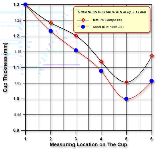
Figure 19.
Influence of punch nose materials on cup thickness distribution that was measured at different points along the cup when Rp = 12mm.
Figure 20 and Figure 21 show the comparison between thickness distributions for the radius of the punch nose in the MMC’s and steel punch materials, respectively. The thickness distributions are similar for all nose radii, but the thickening and thinning location values are different. Due to compression stress, thickening occurs at the flange zone and is proportional to the punch nose radius, and the maximum value of thickening is found when the nose radius is 12 mm. However, the thinning has been reduced when the nose radius increases and occurs above the punch nose radius zone, and the maximum thinning is found when the nose radius is 5 mm, as shown in Figure 21.
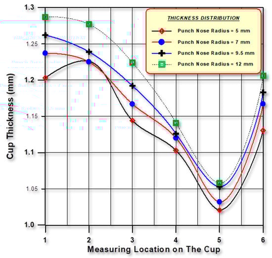
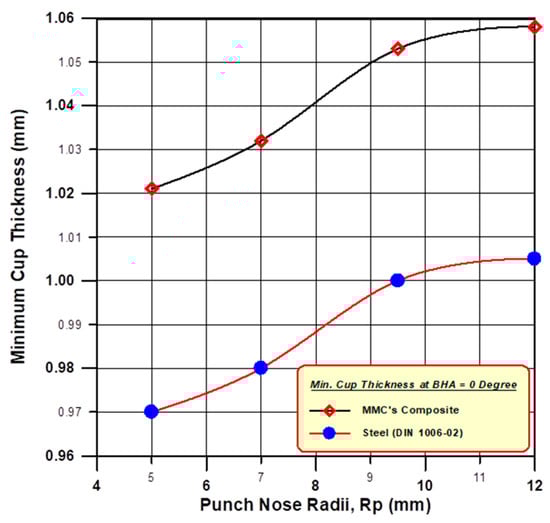
Figure 21.
Influence of punch nose radius on minimum thickness for the MMC’s and steel punch nose materials.
There is approximately a constant difference between the minimum cup thickness that is formed by the MMC’s and steel punch nose materials of 0.05225 mm at location 5 on the cup. This tendency of the minimum cup thickness (tmin) as a function of the punch nose radii (RP) is expressed mathematically via the Weibull Model in Equations (9) and (10) for the MMC’s and steel punch nose materials, respectively.
According to the thickening and thinning zones, the 9.5 mm and 12 mm punch nose radii give acceptable thickening and less thinning at the same time. Then the radius of the punch nose, thickness distribution, and thinning improve. Thinning is somewhat stable when the radius of the punch nose is greater than three times the thickness, and this agrees with what S. RAJU noted, where the thickness at the flange end is the highest due to the hoop stresses produced in the flange, and the lowest thickness was found at the punch nose radius as a result of the minimum punch nose radius [8].
5.5. Cup Height
The blank holder angle and the punch nose radius affect the cup height directly. A comparative study was made between the two materials of the punch nose, where one of them is the MMC’s implemented in this study and the other is the steel DIN 1006-02 that was used by Nasri et al. [22].
The punch nose radius influences the cup height at a 0° blank holder angle (BHA) (φ). The tendency of the cup height varies with respect to the punch nose radius in the MMC’s and steel punch nose, which is similar, as expressed in Equations (11) and (12), respectively, for the composite and steel punch nose materials.
The increment range in cup height by the MMC’s punch nose is from 1.8–2.7 mm when compared to the steel punch nose, as illustrated in Figure 21. The maximum height is obtained at a 9.5 mm punch nose radius with an increment of 13.5%, which is more than that of the steel punch nose.
6. Conclusions
In this research, the deep drawing punch was manufactured via the best mix of hybrid iron-based metal matrix composites (MMC’s) reinforced by a 3% volume fraction of constant mix (20% ZrO2 and 80% Al2O3) using powder metallurgy. The effects of the radius of the punch nose on the drawing force, forming energy, cup surface roughness, cup thickness, and cup height were studied. The following conclusions can be made:
- Drawing force decreases as the punch nose radius increases at the zero blank holder angle. The drawing force by the hybrid MMC’s punch nose is less than the steel DIN 1006-02 by 5%.
- The tendency of the drawing force against the punch nose radius for both the hybrid MMC’s and steel DIN 1006-02 punch nose materials is the same and has the same mathematical expression that is shown in Equations (4) and (5).
- Average surface roughness decreases as the punch nose radius increases from 5–9.5 mm and then increases towards the punch nose radius to 12 mm. The rational function states that the best blank holder angle and RP are 3° and 9.5 mm, respectively.
- The cup thicknesses are low above the punch nose radius to reach its minimum value at location 5 and high at the flange area for all punch nose radii and punch materials. Cup thickness increases as the punch nose radius increases, and the thickness values that are formed by the MMC’s at all locations (six locations) are high compared to that formed by the steel DIN 1006-02 punch.
- Minimum cup thickness that is formed by the hybrid MMC’s is better than that formed by the steel DIN 1006-02 punch nose with an approximate constant difference in minimum thickness of 0.052 mm (5.3%). Both punch nose materials have the same tendency, which is expressed via the Weibull model for the minimum cup thickness as a function of the punch nose radius.
- The effect of the punch nose radius on the cup height is the same as their effects on cup thicknesses with the same advantages of the hybrid MMC’s over steel DIN 1006-02 punch nose materials The tendency of cup height varies with respect to the punch nose radius in the MMC’s and steel punch nose, which is similar.
7. Recommendations for Further Research
- Studying the effects of manufacturing both the punch nose and the blank holder from the hybrid MMC’s on the deep drawing variables.
- Studying the effects of lubricant and particulate lubricant at a variable temperature on the formability parameters in the deep drawing process.
- Using finite element analysis to manufacture the deep drawing die parts (the punch nose, blank holder, and die) from light materials by means of powder metallurgy with high energy sintering using laser and/or plasma.
Author Contributions
Conceptualization, S.M.K.; methodology, S.M.K.; software, S.M.K.; validation, S.M.K. and S.S.; formal analysis, S.M.K.; investigation, S.M.K.; resources, S.M.K. and S.S.; data curation, S.M.K.; writing—original draft preparation, S.M.K.; writing—review and editing, S.S.; visualization, S.S.; supervision, S.S.; project administration, S.S. All authors have read and agreed to the published version of the manuscript.
Funding
This research received no external funding.
Data Availability Statement
Data is unavailable due to privacy.
Conflicts of Interest
The authors declare no conflict of interest.
References
- Suchy, I. Handbook of Die Design; McGraw-Hill Education: New York, NY, USA, 2006. [Google Scholar]
- Reddy, A.C.S.; Rajesham, S.; Reddy, P.R.; Kumar, T.P.; Goverdhan, J. An experimental study on effect of process parameters in deep drawing using Taguchi technique. Int. J. Eng. Sci. Technol. 2015, 7, 21–32. [Google Scholar] [CrossRef]
- Trivedi Nirav, R. Effects of Various Parameters in Deep Drawing Process over Sheet Metal to Get Optimum Result. Int. J. Eng. Dev. Res. 2014, 2, 2321–9939. [Google Scholar]
- Angasu, G.; Reddy, K.S. Deep drawing process parameters: A review. Int. J. Curr. Eng. Technol. 2016, 6, 1204–1215. [Google Scholar]
- Chen, F.K.; Huang, T.B.; Chang, C.K. Deep drawing of square cups with magnesium alloy AZ31 sheets. Int. J. Mach. Tools Manuf. 2003, 43, 1553–1559. [Google Scholar] [CrossRef]
- Jawad, W.K. Investigation of contact interface between the punch and blank in deep drawing process. J. Eng. Technol. 2007, 25, 370–382. [Google Scholar]
- Raju, S.; Ganesan, G.; Karthikeyan, R. Influence of variables in deep drawing of AA 6061 sheet. Trans. Nonferrous Met. Soc. China 2010, 20, 1856–1862. [Google Scholar] [CrossRef]
- Djavanroodi, F.; Abbasnejad, D.S.; Nezami, E.H. Deep drawing of aluminum alloys using a novel hydroforming tooling. Mater. Manuf. Process. 2011, 26, 796–801. [Google Scholar] [CrossRef]
- Gowtham, K.; Srikanth, K.V.N.S.; Murty, K.L.N. Simulation of the effect of die radius on deep drawing process. Int. J. Appl. Res. Mech. Eng. 2012, 2, 12–17. [Google Scholar] [CrossRef]
- Reddy, R.V.; Reddy, D.T.J.; Reddy, D.G. Effect of various parameters on the wrinkling in deep drawing cylindrical cups. Int. J. Eng. Trends Technol. 2012, 3, 53–58. [Google Scholar]
- Raju, P.; Venkateswarlu, G.; Davidson, M.J. Formability Studies on AA 6061 Sheet Metal or Automotive Body Structures using Deform-2D. Int. J. Adv. Sci. Technol. Res. 2012, 4, 638–644. [Google Scholar]
- Purushotham, A. Simulation studies on deep drawing process for the evaluation of stresses and strains. Int. J. Comput. Eng. India 2013, 3, 40–47. [Google Scholar]
- Dilmec, M.; Halkaci, H.S.; Ozturk, F.; Livatyali, H.; Yigit, O. Effects of sheet thickness and anisotropy on forming limit curves of AA2024-T4. Int. J. Adv. Manuf. Technol. 2013, 67, 2689–2700. [Google Scholar] [CrossRef]
- ISO E. 12004-2; Metallic Materials—Sheet and Strip—Determination of Forming-Limit Curves—Part 2: Determination of Forming-Limit Curves in the Laboratory. Beuth: Berlin, Germany, 2008.
- Chiorescu, D.; Nagî, G.; Mihalache, Ş.; Dodun, O. Analysis of Drawing Force Variation for Cylindrical Cups in Relation to Die Relative Radius and Angle. Acad. J. Manuf. Eng. 2013, 11, 16–19. [Google Scholar]
- Zein, H.; El-Sherbiny, M.; Abd-Rabou, M.; El Shazly, M. Effect of die design parameters on thinning of sheet metal in the deep drawing process. Am. J. Mech. Eng. 2013, 1, 20–29. [Google Scholar] [CrossRef]
- Cups, T.O.D.D.O. Effect of Blank Holder Type on Deep Drawing of Cups. Iraqi J. Mech. Mater. Eng. 2013, 13, 106–119. [Google Scholar]
- Alin, P.; Ioan, M.; Ioan, R.; Florin, B. Parameters Influence on Wrinkling in Deep Drawing Cylindrical CUPS. Nonconv. Technol. Rev. Rev. De Tehnol. Neconv. 2013, 17, 59–63. [Google Scholar]
- El Sherbiny, M.; Zein, H.; Abd-Rabou, M. Thinning and residual stresses of sheet metal in the deep drawing process. Mater. Des. 2014, 55, 869–879. [Google Scholar] [CrossRef]
- Shah, K.; Bhatt, D.; Panchal, T.; Panchal, D.; Dogra, B. Influence of the Process Parameters in Deep Drawing. Int. J. Emerg. Res. Manag. Technol. 2014, 3, 16–22. [Google Scholar]
- Singh, C.P.; Agnihotri, G. Study of deep drawing process parameters: A review. Int. J. Sci. Res. Publ. 2015, 5, 1–15. [Google Scholar]
- Namer, N.S.; Nama, S.A.; Thabit, J.W. Numerical and Experimental Study on Deep Drawing Process for AA2024-T4 Sheet. J. Appl. Exp. Mech. 2015, 1, 1–9. [Google Scholar]
- Al-Hamdani, A.H. Design and performance analysis of contact lens materials for chromatic and polychromatic aberrations correction. Eng. Technol. J. 2018, 36, 1016–1021. [Google Scholar] [CrossRef]
- Khazaal, S.M.; Nimer, N.S.; Szabolcs, S.; Abdulsamad, H.J. Study of manufacturing and material properties of the hybrid composites with metal matrix as tool materials. Results Eng. 2022, 16, 100647. [Google Scholar] [CrossRef]
- Bahrami, A.; Soltani, N.; Soltani, S.; Pech-Canul, M.; Gonzalez, L.; Gutierrez, C.; Möller, A.; Tapp, J.; Gurlo, A. Mechanical, thermal and electrical properties of monolayer and bilayer graded Al/SiC/rice husk ash (RHA) composite. J. Alloys Compd. 2017, 699, 308–322. [Google Scholar] [CrossRef]
- Bahrami, A.; Pech-Canul, M.; Soltani, N.; Gutiérrez, C.; Kamm, P.; Gurlo, A. Tailoring microstructure and properties of bilayer-graded Al/B4C/MgAl2O4 composites by single-stage pressureless infiltration. J. Alloys Compd. 2017, 694, 408–418. [Google Scholar] [CrossRef]
- Soltani, N.; Bahrami, A.; Pech-Canul, M.; Gonzalez, L.; Möller, A.; Tapp, J.; Gurlo, A. Electrical and thermomechanical properties of CVI-Si3N4 porous rice husk ash infiltrated by Al-Mg-Si alloys. J. Alloys Compd. 2017, 696, 856–868. [Google Scholar] [CrossRef]
- Kumar, G.V.; Mageshvar, R.; Rejath, R.; Karthik, S.; Pramod, R.; Rao, C. Characterization of glass fiber bituminous coal tar reinforced Polymer Matrix Composites for high performance applications. Compos. Part B Eng. 2019, 175, 107156. [Google Scholar] [CrossRef]
- Nagpal, G.R. Metal forming processes, (A Textbook for Engineering Students), Fourth Edition, KHANNA PUBLISHERS, Darya Ganj, New Delhi 110 002, 1998. ISBN: 9788174090177. Available online: https://www.kopykitab.com/Metal-Forming-Processes-Fourth-Edition-by-G-R-Nagpal (accessed on 1 July 2023).
- Özek, C.; Bal, M. The effect of die/blank holder and punch radiuses on limit drawing ratio in angular deep-drawing dies. Int. J. Adv. Manuf. Technol. 2009, 40, 1077–1083. [Google Scholar] [CrossRef]
- Rehman, A.U.; Karakas, B.; Mahmood, M.A.; Başaran, B.; Rehman, R.U.; Kirac, M.; Khraisheh, M.; Salamci, M.U.; Ünal, R. Additive manufacturing of Inconel-625: From powder production to bulk samples printing. Rapid Prototyp. J. 2023; ahead-of-print. [Google Scholar] [CrossRef]
- Khorasani, M.; Ghasemi, A.; Leary, M.; Downing, D.; Gibson, I.; Sharabian, E.G.; Veetil, J.K.; Brandt, M.; Bateman, S.; Rolfe, B. Benchmark models for conduction and keyhole modes in laser-based powder bed fusion of Inconel 718. Opt. Laser Technol. 2023, 164, 109509. [Google Scholar] [CrossRef]
- Standard IS. 4287:1997; Geometrical Product Specifications (GPS)–Surface Texture: Profile Method–Terms, Definitions and Surface Texture Parameters. International Organization for Standardization: Geneva, Switzerland, 1998.
Disclaimer/Publisher’s Note: The statements, opinions and data contained in all publications are solely those of the individual author(s) and contributor(s) and not of MDPI and/or the editor(s). MDPI and/or the editor(s) disclaim responsibility for any injury to people or property resulting from any ideas, methods, instructions or products referred to in the content. |
© 2023 by the authors. Licensee MDPI, Basel, Switzerland. This article is an open access article distributed under the terms and conditions of the Creative Commons Attribution (CC BY) license (https://creativecommons.org/licenses/by/4.0/).