Article

Bolt-Hole Elongation of Woven Carbon-Epoxy Composite Plates and Joints Using the Digital Image Correlation Technique

Department of Mechanical Engineering, Polytechnique Montreal, Montreal, QC H3C 3A7, Canada
*
Author to whom correspondence should be addressed.
J. Compos. Sci. 2024, 8(5), 180; https://doi.org/10.3390/jcs8050180
Submission received: 6 April 2024 / Revised: 28 April 2024 / Accepted: 8 May 2024 / Published: 12 May 2024
(This article belongs to the Special Issue Recent Progress in Hybrid Composites)

Abstract

:
The elongation of the bolt hole is an important parameter for assessing the failure of bolted joints. However, direct experimental measurement using strain gauges and extensometers is difficult. This article shows that digital image correlation (DIC) can overcome the difficulties and provide important indications of the failure mechanisms of bolted joints. Hole elongation was measured using DIC in the following carbon/epoxy composite configurations: standard open-hole tensile (OHT) and filled-hole tensile (FHT), single-lap shear only-bolted (OB), and single-lap shear hybrid-bolted/bonded (HBB) joints. For each configuration, the hole-elongation changes were tracked for cross-ply (CP) and quasi-isotropic (QI) stacking sequences with two thicknesses. In the tensile load direction for OHT and FHT cases, CP showed a greater hole elongation than QI. However, the opposite trend was observed in the transverse direction. In OB joints, bypass loads contributed more to the hole elongation than bearing action. In HBB joints, it has been observed that the adhesive significantly reduces hole elongation, particularly for CP configurations. Moreover, it was found that in HBB joints, hole elongation was independent of laminate lay-up, while it was very determinative in OB joints.

1. Introduction

The structural vulnerability of any assembled mechanical system often lies at its joints. A notable benefit of incorporating composite materials in diverse applications is their ability to consolidate multiple parts into singular components, thereby reducing the need for extensive joining. Nonetheless, the necessity for joining persists, requiring techniques like bonding or hole drilling [1,2]. Three main classes of joining are used to connect thermoset composite components: mechanical fasteners, adhesive bonding, and hybridization of the two [3]. However, the presence of joints increases the flexibility of the entire structure. The added flexibility leads to not only the elongation of the hole and the associated bearing damage, but also the deformation/rotation of the bolt [4].
Several studies have addressed the hole elongation of open and filled-hole specimens. Sawicki and Minguet [5] studied the failure mechanisms of open and filled holes in carbon/epoxy laminates under compressive loads. The addition of a fastener to an open-hole specimen creates a load path called a through-fastener load path, which reduces the deformation around the hole as the bolt takes up the majority of the load. This, in turn, reduces the amount of compressive deformation that the hole exhibits. Sola et al. [6] investigated the damage mechanisms of pin-bearing carbon-fiber composite laminates by considering the displacement of the pin. They found that a large notch elongation may promote the transition from bearing failure to either shear-out or cleavage failure. Saleh et al. [7] studied the effect of a circular hole in open-hole tensile (OHT) carbon-fiber woven composites by incorporating digital image analysis (DIC), which could properly capture the hole elongation of the specimen as it underwent uniaxial tension until failure. Junshan et al. [8] examined the effect of strain on the hole circumference of OHT composite laminates. By utilizing DIC, strain values around the hole were plotted as a function of the angular position with respect to the direction of the applied load. Using these strain values, the elongation of the hole can be calculated.
In the fatigue testing of a joint structure, the hole elongation after N cycles is calculated by subtracting the displacement at the first cycle from that at the Nth cycle [9]. The results obtained previously demonstrated that one of the reasons for bearing failure is the significant elongation of the joint hole, and a high clamp-up torque results in small hole elongations. Strain gauges installed between the blot rows of a multi-bolted joint can be used in quasi-static and fatigue testing to analyze the strain distribution and load transfer [10,11]. The measurements could also be considered a representation of the hole elongation. Girard et al. [12] measured hole elongation using an extensometer and showed that the composite lay-up can affect the hole elongation in such a manner that angle-ply and quasi-isotropic (QI) lay-ups present similar hole elongations that are larger than the cross-ply (CP) hole elongation. Hole elongation was considered the ultimate failure mode in the fatigue testing of double-lap, multi-bolted composite joints [13]. It was found that in joints with a loose-fit hole, hole elongation commenced sooner, and clearance had the greatest effect on failure initiation but a lower effect on ultimate failure. Another fatigue testing result showed that long fiber-reinforced leaf spring joints experienced lower hole elongation than unreinforced or short fiber-reinforced joints for all stress levels tested [14]. Wei et al. [15] considered bolt-hole elongation (BHE) reaching 4% of the hole diameter as an indication of composite joint failure in fatigue testing. Their results showed that neat-fit joints experienced the least BHE compared to other interference fits.
Li et al. [16] experimentally found that the BHE increases as the number of fatigue cycles increases, while it decreases gradually with an increase in interference-fit sizes. X-ray images were used to observe the hole elongation in the single-lap (SL) composite joint. The results showed that the advent of hole elongation is more evident in countersunk fasteners than in non-countersunk fasteners because of the additional compressive deformation induced by the countersunk head of the bolt [17]. The cyclic loading of a composite joint revealed that an abrupt increase in BHE occurred in high-clamp-up torqued configurations, whereas for the low-clamp-up configurations, a gradual BHE increase was observed [18]. An improved finite-element (FE) model for single-bolt SL composite joints was developed by Liu et al. [19]. A good agreement was obtained between the bolt-hole deformation measurement using an extensometer and the FE simulation, which validated the effectiveness of the adjusted 3D FE model.
The combined effects of fatigue loading and seawater aging on the bearing performance and failure mechanism of SL composite bolted joints were studied by Zhang et al. [20], and they found that the hole elongation under quasi-static loading for fatigue-tested specimens was noticeably smaller than that of non-fatigued specimens. Sajid et al. [21] investigated the role of washer size on the BHE of an SL basalt composite joint. A significant hole elongation was observed for larger washer configurations, but no apparent hole elongation was observed for small washer configurations. A computed tomography (CT) scan of an SL riveted woven carbon composite joint showed that growth in the hole diameter due to hole elongation had its maximum values at the top plies, while it decreased step-wise while moving in the thickness direction to the middle plane and then the bottom plies [22]. CT and scanning electron microscopy (SEM) images also contributed to the observation of fiber kinking and wedge matrix cracking. The interaction of these damage modes leads to the formation of through-thickness shear cracks, the propagation of which causes permanent bolt-hole deformation [23].
While hole elongation is of significant concern in cyclic loading and researchers have focused excessively on it, the hole elongation of fatigue-tested composite joints was observed to be remarkably smaller than that of tensile-tested joints [20]. Therefore, it is important to investigate the hole-elongation phenomenon and its effects on the mechanical behavior of multi-bolted SL composite joints under quasi-static loading. However, in the literature, experimental measurements were primarily performed using displacement records of extensometers mounted on the tested specimen, which are always associated with some errors and inaccuracies due to the movement of the fixture of the tensile test machine. Therefore, the experimental measurement under quasi-static loading is quite challenging.
The present study aimed to use DIC technology to precisely measure the hole-elongation development and its effects for different composite configurations: open-hole tension (OHT), bolted filled-hole tension (FHT), only-bolted (OB), and hybrid-bolted/bonded (HBB) SL joints. The chosen composite lay-ups are the two well-known types: CP and QI lay-ups, which were manufactured using plain weave fabrics with thicknesses of 8 and 12 layers. The obtained results can assist in gaining a profound understanding of the hole-elongation development and the factors influencing it for the aforementioned configurations. Additionally, the DIC results are expected to provide more details in this regard to contribute to composite joining design for different types of aeronautic structures.

2. Materials and Methods

Experimental Procedure

Carbon-fiber epoxy laminates reinforced with epoxy were manufactured using the vacuum-assisted resin infusion (VARI) process. The composite laminates were composed of 3K plain weave carbon fabric with a surface weight of 193 g/m2 and a commercial Araldite epoxy resin system [24]. The average thicknesses of the panels were approximately 2.6 mm and 1.6 mm for 12 and 8 layers, respectively. The QI and CP laminate configurations were obtained by orienting the woven plies, the lay-up of which is given in Table 1. Moreover, Table 1 lists the average recorded nominal strengths in unnotched tensile standard (TS), OHT, and FHT tests for CP and QI.
The specimens corresponding to TS, OHT, and FHT tests were manufactured according to ASTM-D3039 [25], ASTM-D5766 [26], and ASTM-D6742 [27], respectively. Moreover, SL multi-bolted joints were designed and manufactured according to ASTM-D5961 [28]. The two parts in SL bolted joints were fastened using steel hex-head shear bolts (NAS6204-4) with a diameter of 6.35 mm, nuts (MS21042-4), and cadmium-plated steel washers (NAS1149F0463P) with an internal diameter of 6.73 mm and an external diameter of 12.70 mm on both the head and side nuts. A tightening torque of 5 Nm was applied to each bolt using a Tohnichi Dial Torque Wrench DB25N-S. A specialized carbide drill bit with a diameter of 6.35 mm, provided by YG-1 America, Inc., was utilized to drill in the laminate coupons [3]. The HBB joints were manufactured by simply adding an adhesive between the fraying surfaces of the OB joints. The applied adhesive was the same as the epoxy resin used for manufacturing the composite laminate [29]. Throughout this paper, the prefixes OHT, FHT, OB, and HBB are added to the laminate code, for example, HBB-CP12 and OHT-QI8, to specify the class of configurations. The geometrical configurations of OHT, SL OB, and HBB composite joints are shown in Figure 1. Furthermore, at least four identical coupons were tested for each configuration at a constant standard crosshead displacement rate of 2 mm/min. Uniaxial tests were conducted using a servo-hydraulic MTS machine model 810. The 810 MTS offers extensive testing capabilities and a load capacity of up to 100 kN. It is appropriate for fatigue, fracture, and monotonic tests.
In this study, DIC technology was used to measure hole deformations. The principle of this optical measurement technique is based on the tracking of a random pattern on the specimen surface by matching the local distribution of pixel concentration, i.e., subsets, between the undeformed and deformed images in a specific time interval. Two 5-megapixel Pointgrey Grasshopper charge-coupled device (CCD) cameras with a pixel size of 3.45 were used for the camera sensor [3]. The setup also included a light source to illuminate the specimens. All specimens were spray-painted with white spray paint, following which a random speckle pattern was applied. The cameras captured photos at a rate of 2 frames per second. The captured images were processed using Vic-3D v7.2.4 (Correlated Solutions Inc., Irmo, SC, USA). Further details of the DIC system configuration are provided in Ref. [3].

3. Results and Discussion

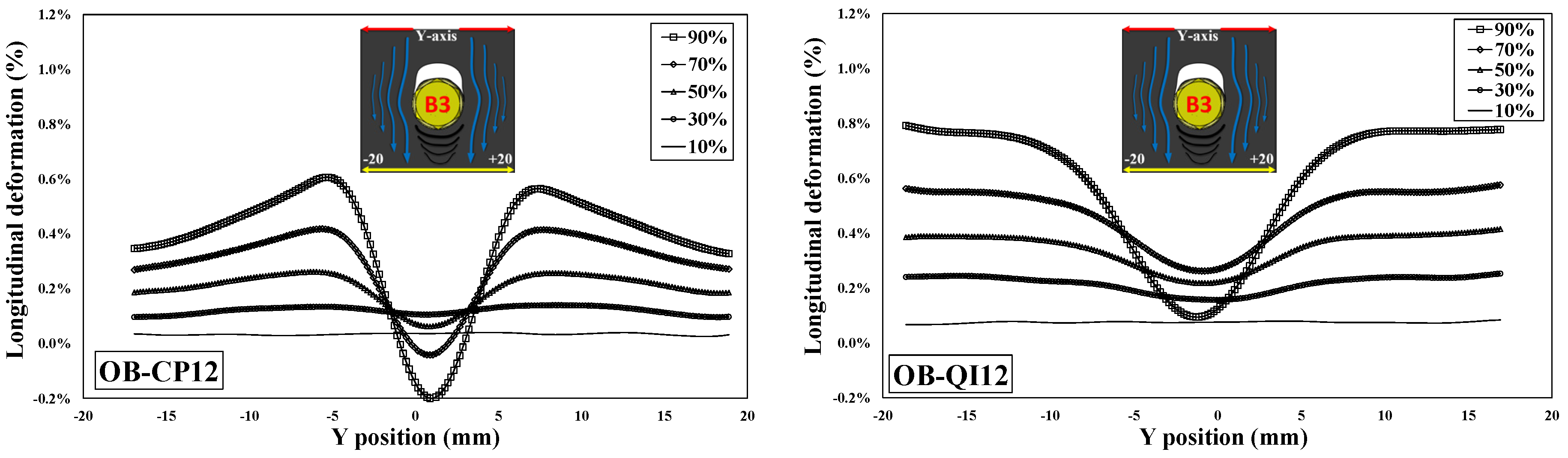
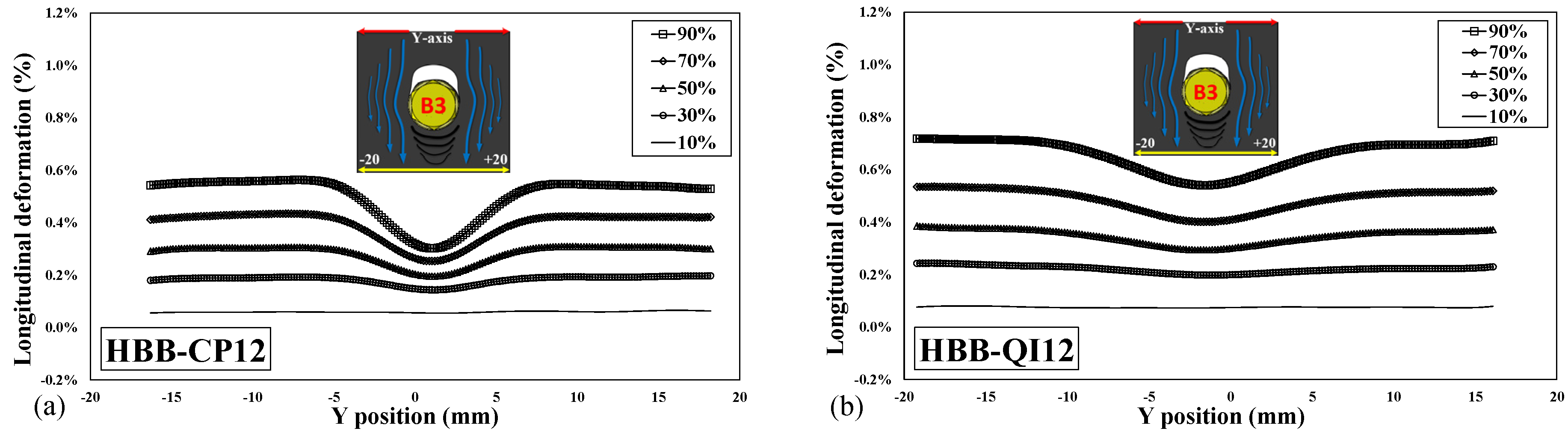
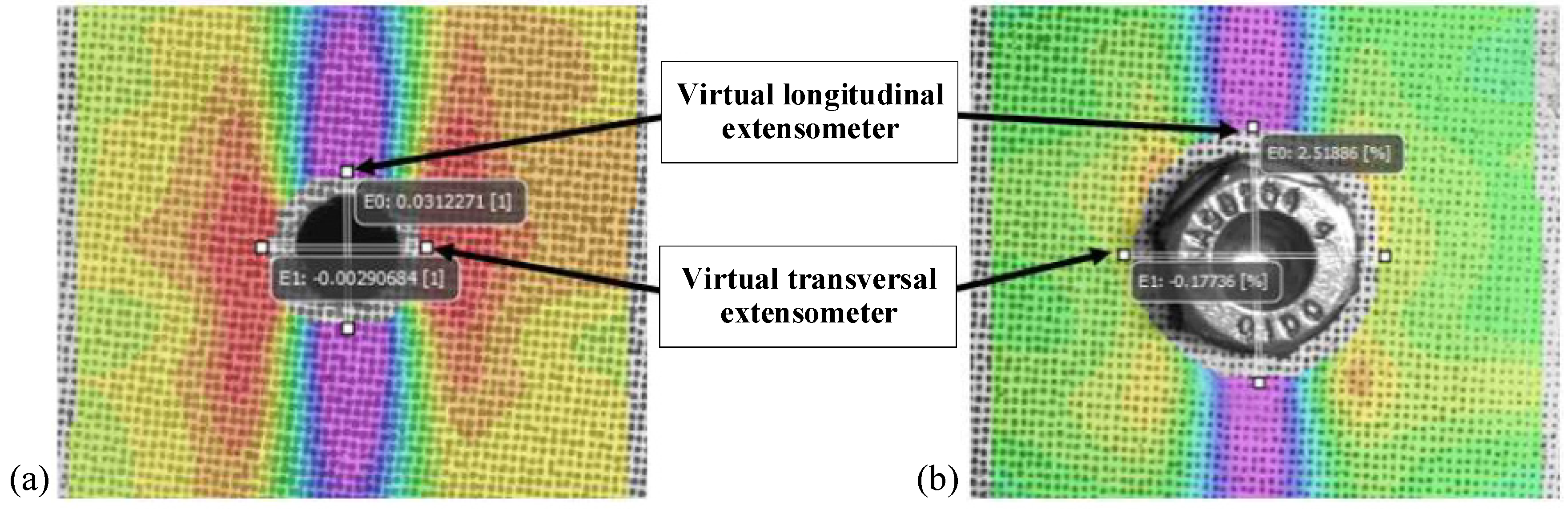
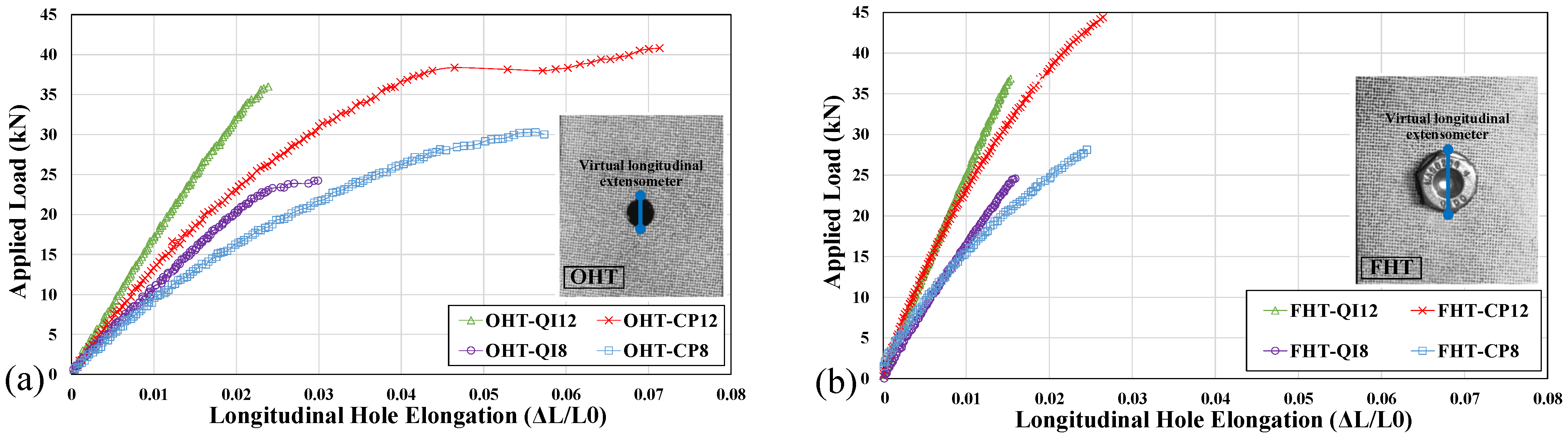
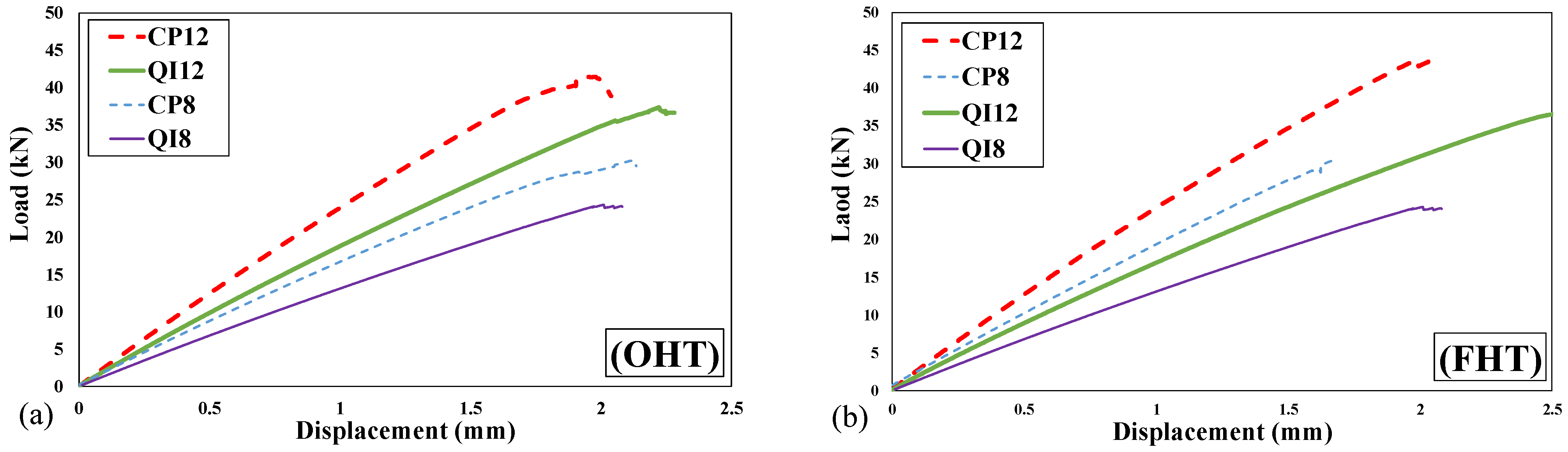
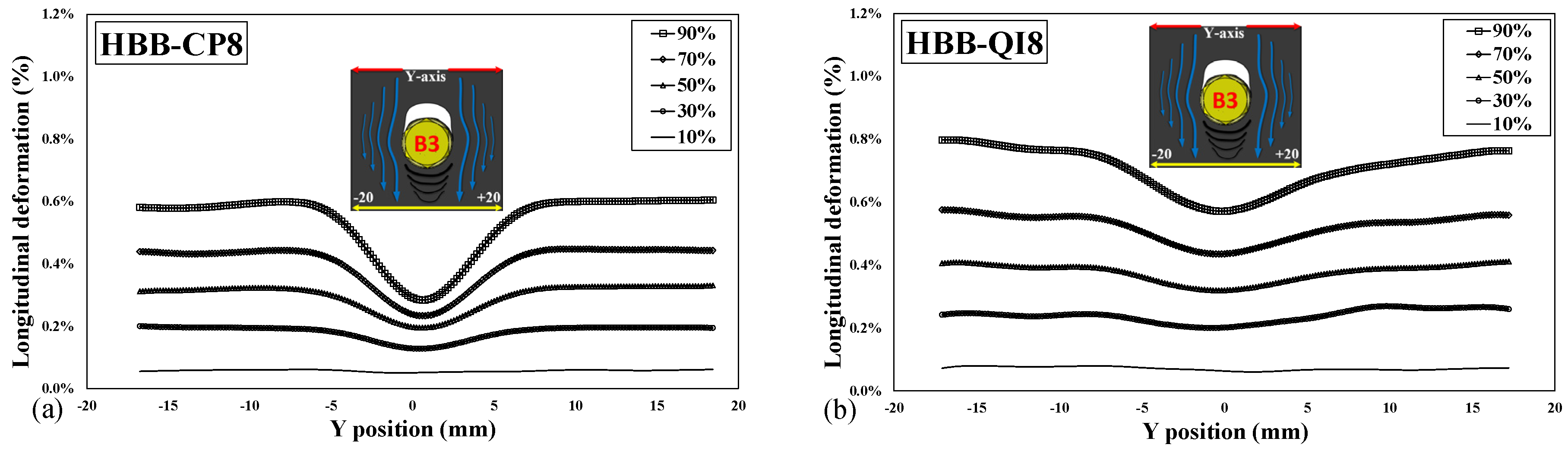
3.1. Hole Deformation

Prior to investigating the hole elongation of OB and HBB joints, this phenomenon was studied for OHT and FHT, which are widely used in the aeronautical industry for material qualification purposes [30,31]. During tensile testing, the deformation of the hole was measured in the longitudinal and transverse directions. The deformation of the hole along the longitudinal direction (the loading direction) is labeled as LHE, short for longitudinal hole elongation, and that along the transverse direction to the loading is labeled as THC, short for transverse hole compression. As shown in Figure 2, the LHE and THC measurements were retrieved by applying two virtual extensometers (VEs) within Vic-3D software: one in the longitudinal direction and the other in the transverse direction.
Figure 3 plots LHE against the applied tensile load of OHT and FHT specimens for each laminate. Because CP laminates have twice as many fibers oriented in the load direction as QI laminates, at first glance, it can be expected that their higher stiffness will result in lower hole elongation. However, for the OHT test, as shown in Figure 3a, the opposite result is obtained. This result may stem from the fact that the CP configuration has a higher notch sensitivity and stress concentration than the QI configuration [3,30]; hence, it significantly influences the CP longitudinal hole elongation from the beginning of the test.
It is interesting to observe that for a given thickness in the case of FHT (Figure 3b), unlike the OHT case, the hole elongation for the CP configuration is slightly less than that of the QI configuration up to a certain load. Beyond this load, the CP curves gradually diverge, and a greater hole elongation is observed as compared to the QI configuration. It is suggested that at lower levels of applied load, filling the hole with a clamped bolt greatly reduces the longitudinal and transversal deformation because the bolt upholds the geometric integrity of the hole; consequently, the notch sensitivity does not play a crucial role. However, at higher load levels, the higher stress concentration in the CP configuration results in increased hole elongation. The benefit of the reduction in LHE with a clamped bolt does not seem to contribute to the strength retention of the laminates. Because the holes in the FHT specimens undergo less deformation, the hole boundary exhibits a smaller degree of damage. This, in turn, leads to less energy absorption and, hence, less stress relief, which explains why the FHT specimens in this investigation have a lower tensile strength than the OHT specimens (Table 1). Delamination at the edge of the hole during testing leads to a decrease in stress concentration [32]. CP12 is an outlier because its OHT strength is less than its FHT strength. In general, it can be inferred that in a woven carbon-fiber composite plate with a hole, the bolt can provide a good system of control, creating a delaying effect on the stress concentration and notch sensitivity of the corresponding laminate as well as blocking the damage progression to some extent.
Figure 4a,b show the load–displacement curves of OHT and FHT, respectively. These curves show the macroscopic deformation, which is the total displacement of the specimen between the grips and comprises the LHE. From Figure 4a,b, the laminates in the increasing order of macroscopic elongation are CP12, QI12, CP8, QI8, CP12, CP8, QI12, and QI8. It is interesting to note that this order of elongation is different from that shown in the LHE curves (Figure 3a,b), in which the values of QI are always greater than those of CP for the given thicknesses. It can be concluded that the load–displacement curves are not reliable in predicting the microscopic elongation of the hole (LHE), and the DIC technique is a necessary tool for extracting such data.
Figure 5 plots THC against the applied tensile load in OHT and FHT specimens for each laminate. The following observations can be made by comparing OHT with FHT:
  • The clamped bolt upholds the geometric integrity of the hole because FHT laminates have a lower THC than OHT laminates.
  • CP laminates, which have a large LHE, possess a lower THC than QI laminates. This implies that the hole elongates more in CP than in QI, while the CP hole exhibits less THC than the QI hole. This trend was observed for both OHT and FHT specimens (Figure 5a and Figure 5b, respectively).
The difference in LHE and THC between CP and QI may occur because of the 45° plies in the QI laminate. Figure 6 illustrates the strain contour plots (longitudinal and transverse) at 40% of the failure load for CP12 and QI12. The arrows depict the direction and magnitude of the strains with respect to the axis of the peak strains for each strain plot. As shown in Figure 5a, the axis of the peak strains is the transversal axis from the hole edge to the free edge of the specimen. The axis of the peak strains is dependent on the laminate configuration and whether the strain is longitudinal or transversal. As shown in Figure 6a, the peak longitudinal strains (Ɛxx) for CP12 are concentrated at the hole boundary and stay elevated along the longitudinal direction owing to the 0° plies. The axis of symmetry for the strains coincides with the y-axis. However, the axis of the peak strains for QI12 (Figure 6b) is at an angle of approximately 45° to the y-axis (butterfly pattern). The fact that the CP peak strains pull perpendicularly to the hole boundary and those of QI pull at an angle from the hole boundary might explain why the LHE of the CP configuration is higher than that of the QI configuration (Figure 3).
The perpendicular deformation of the hole has increased leverage over the longitudinal deformation as compared to deformation at an angle. The peak transversal strains (Ɛyy) for CP12 (Figure 6c) are concentrated at the hole boundary and stay somewhat elevated along the longitudinal direction. This trend is similar to that exhibited in the longitudinal strain plots; however, there is a clear difference. The compressive transversal strains occur in half of the specimen (upper-right and lower-left sides of the notch) with no clear axis of symmetry. The QI lay-up exhibits (Figure 6d) the same 45° axis, along which the peak compressive strains are distributed. This favors an increase in THC values for QI compared to CP lay-ups. Although CP12 and QI12 were used here as examples, CP8 and QI8 exhibited the same phenomenon. This result indicates that the laminate lay-up has a significant influence on the overall hole deformation of the composite plate.

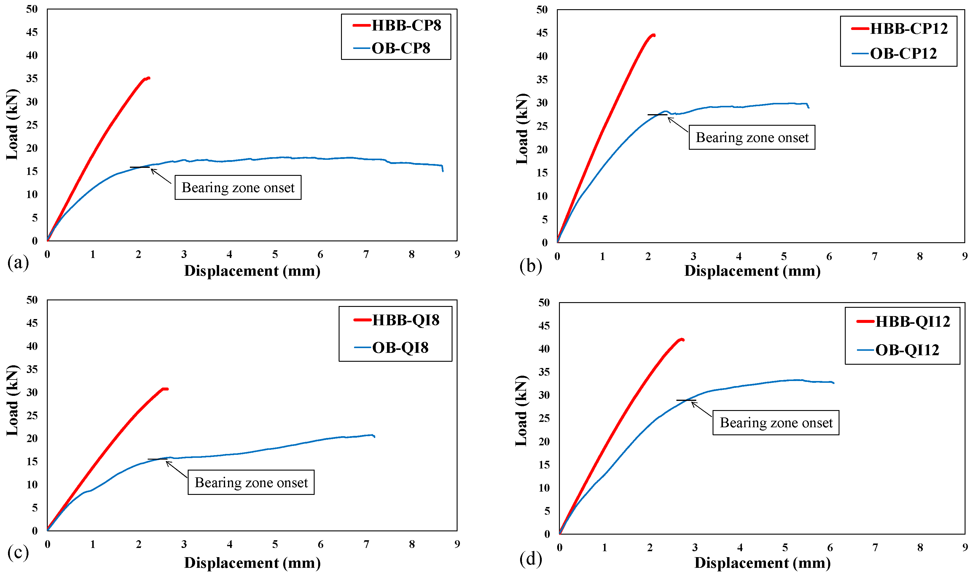
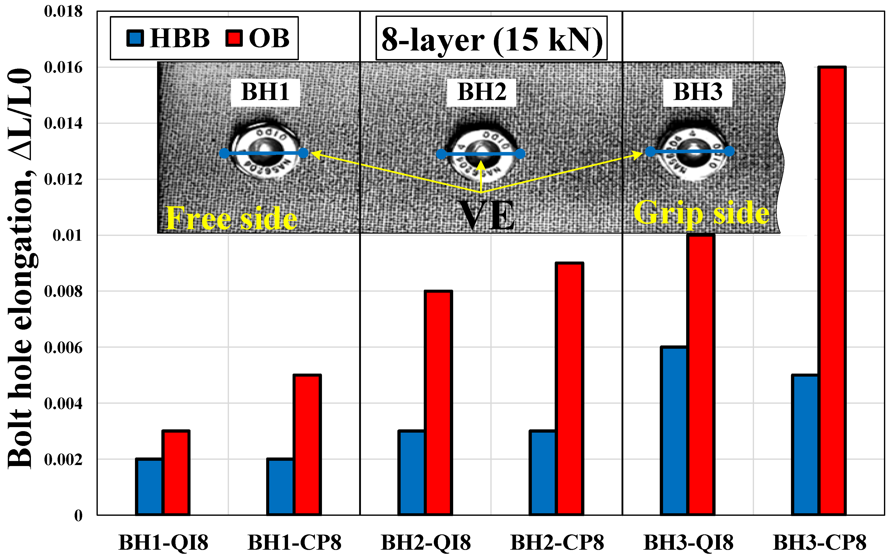
3.2. Bolt-Hole Elongation (BHE) in Joints

Following the investigation of hole deformation in OHT and FHT, this section investigates the same phenomenon for SL joints with significantly different geometrical configurations and behaviors. The test results were analyzed based on the DIC data recorded for eight different SL joint configurations (see Table 1), the corresponding failure loads and load–displacement curves of which are shown in Figure 7 and Figure 8, respectively. As previously mentioned, the BHE (also called hole wear in fatigue testing) is of significant concern in the cyclic and quasi-static loading of a joint. Similar to the previous section, three VEs were placed diametrically in the axial direction at the bolt positions (Figure 9b) and labeled as VE3, VE2, and VE1. This section comprises the following three subsections: Section 3.2.1 studies the case of OB joints (Figure 10 and Figure 11), Section 3.2.2 investigates HBB joints (Figure 12 and Figure 13), and finally, Section 3.2.3 compares the two configurations, i.e., OB vs. HBB, in a bar chart (Figure 14) to determine the effect of hybridization on hole elongation development.

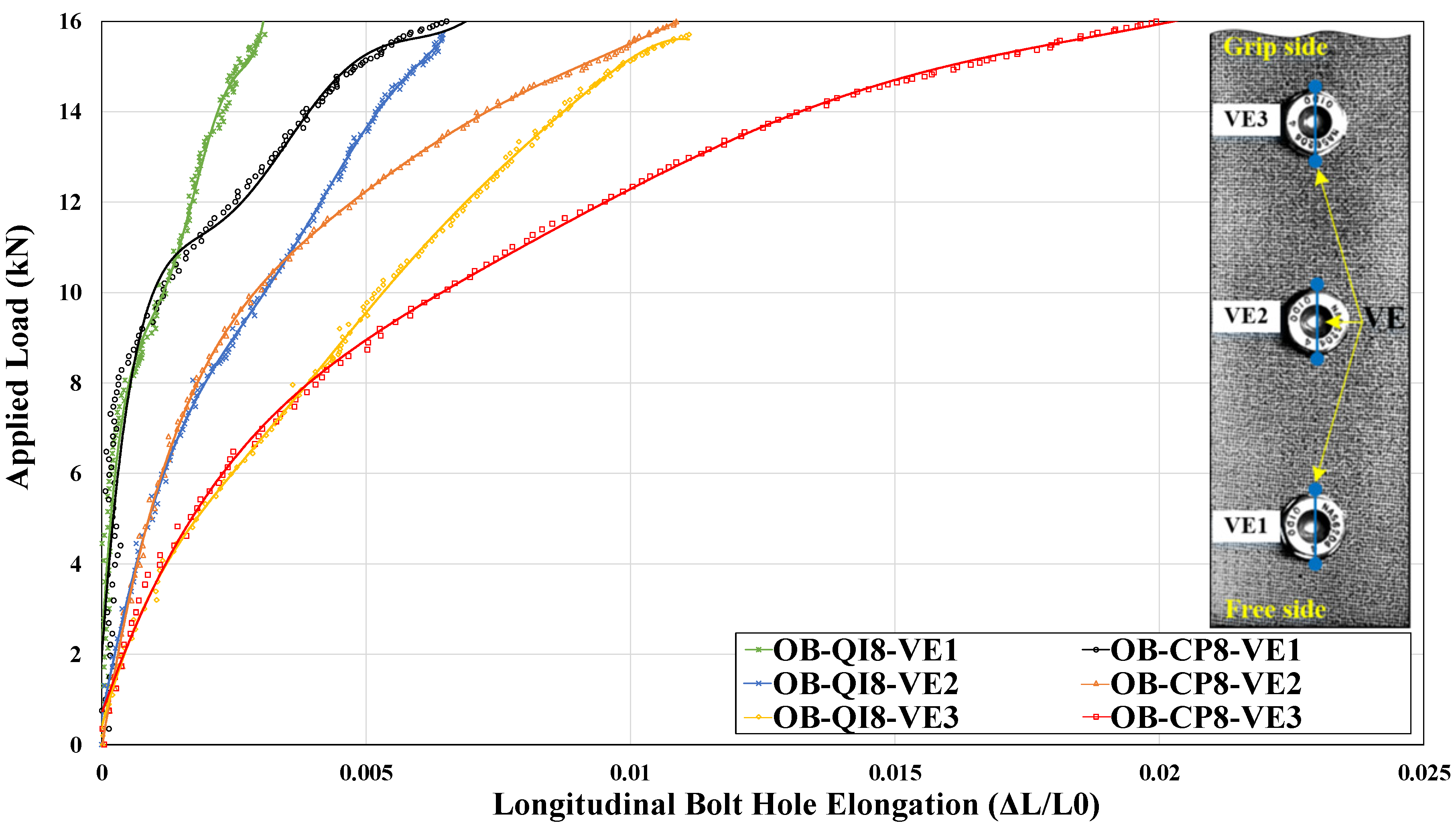
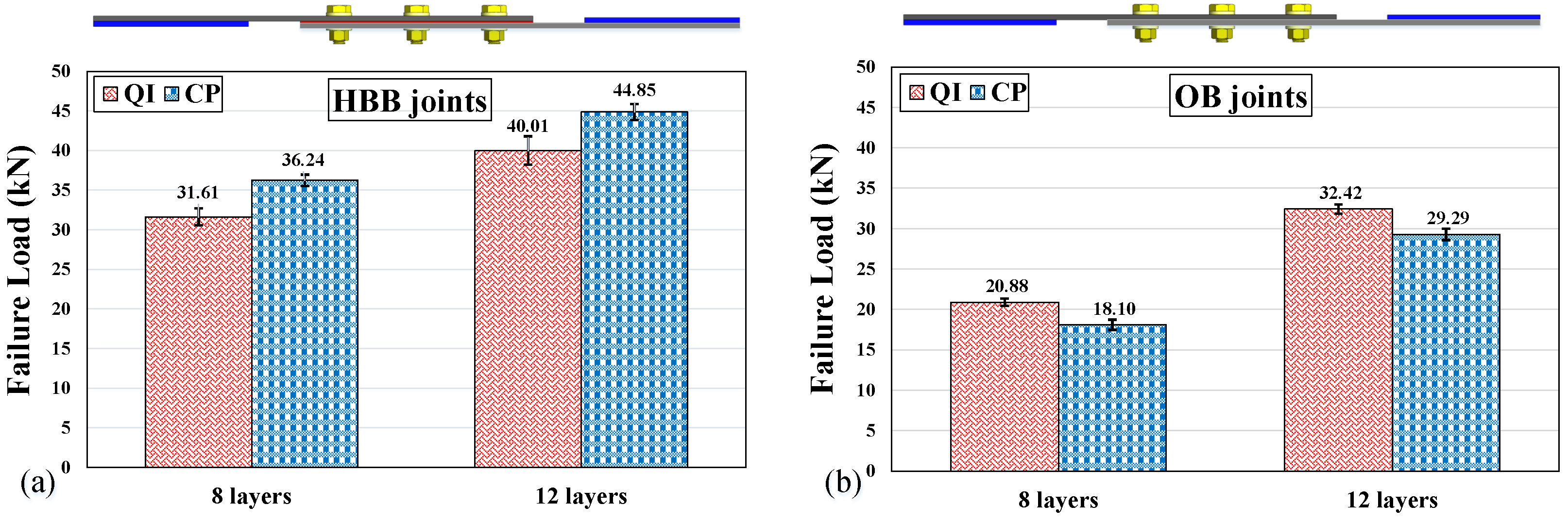
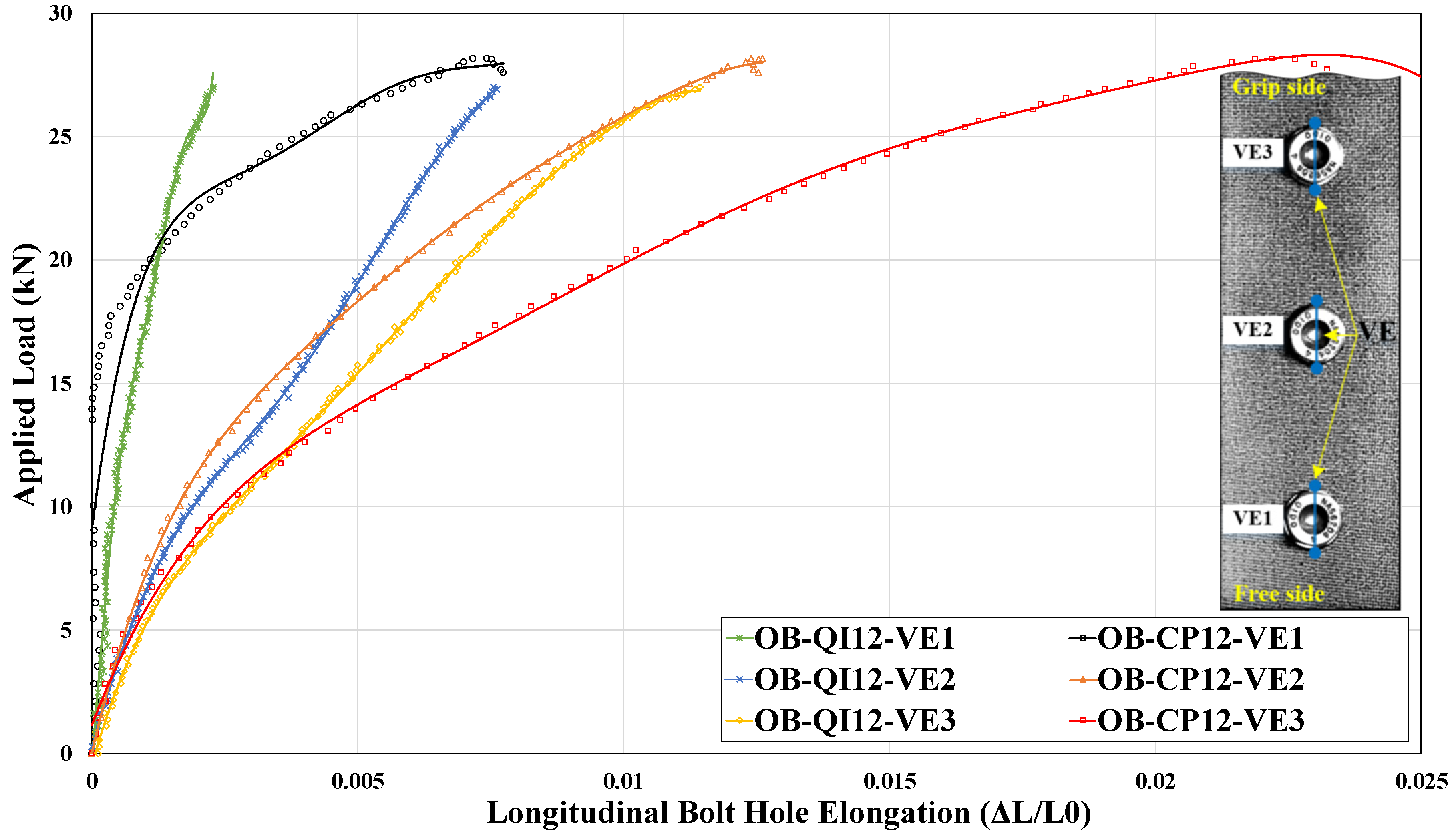
3.2.1. BHE of Only-Bolted (OB) Joints

In general, BHE describes the deformation of the hole caused by both the bearing load through the bolt shank pressure [33] and the bypass load around the hole. Figure 9a shows a schematic of the contribution of the bearing and bypass loads around the critical bolt, i.e., B3, where net-tension failure occurs owing to the highest value of the bypass/bearing load ratio. Moreover, Figure 9b illustrates the position of the previously mentioned VEs.
Figure 10 shows the BHE of the OB joints up to the load level corresponding to the onset of bearing damage identified in Figure 8. A curve fit of the DIC data was used to improve visualization. For all the laminate lay-ups (CP and QI) tested, BHE gradually decreased when proceeding from hole 3 (grip side) towards hole 1 (free side). This is due to the stepwise reduction in the bypass/bearing load ratio in the mentioned direction [3]. Therefore, it could be suggested that the influence of the bypass load is greater than that of the bearing action in forming the hole elongation for a given laminate lay-up of the multi-bolted SL composite joint. The results for the thinner joints (see Appendix A) illustrate that at equal load levels, thinner configurations experienced more longitudinal hole elongation than the thicker ones, which seemed to be more pronounced at B3. In SL joints, this phenomenon may be attributed to the higher induced bending stress in thicker joints due to the greater geometrical eccentricity [34]. Consequently, at the fastener location, the outer surface of thicker laminates may experience more compression than thinner ones, which can lead to an overall reduction in BHE.
The relationship between BHE and tensile loading can represent BHE stiffness. The curves of CP exhibited two distinguishable segments of BHE stiffness. The first segment of the curve is predominantly linear and has a high slope. In the second segment, the slope of the curves abruptly starts to decrease, crossing the QI, whose curves are rather single-slope, and indicating minor changes in BHE stiffness. It is interesting to note that the same behavior is also observed in the FHT case (Figure 3b), in which CP experienced a lower BHE than QI for both thin and thick configurations at lower load levels. However, as the load increased, the BHE curves of CP surpassed those of QI, resulting in greater elongation in CP. It is worth noting that, with an acceptable estimation, the CP curves of VE3, VE2, and VE1 surpassed those of QI at approximately 40%, 55%, and 60% of the failure load, respectively. Therefore, it can be observed that for B3, the crossing of the curves occurred much sooner and approximately at the moment of transition where the load transfer mechanism changed from friction between faying surfaces to bolt load bearing [34]. According to the previously mentioned percentages, the bolt shanks of B2 and B1 are considered to have come into contact with the bolt hole with a noticeable delay compared to that of B3. Figure 11 shows another representation of the transition of the load transfer mechanism occurring at the B3 location. To achieve this, a virtual yellow line (inset in Figure 11) perpendicular to the load direction was drawn from edge to edge (Y position ranging from −20 mm to +20 mm) and at a distance of 2d (d is the hole diameter) from the center of the corresponding hole. The results show the evolution of longitudinal deformation from 10% to 90% of the failure load in steps of 20%. It can be seen that at lower load levels (10% and 30%), the distribution of longitudinal deformation, i.e., axial strain, below the bolt is more level than that of the higher ones. This could be attributed to the friction forces engaged between the faying surfaces of the plates, which subsequently prevented the bolts from load transferring at lower load levels. Moreover, Figure 11 illustrates the consequence of the greater BHE of CP compared to QI in terms of bearing formation under B3. The higher strength of the OB joint made of QI compared to that made of CP shown in Figure 7 may be explained by the fact that QI experiences less hole elongation than CP. Indeed, hole elongation in bolted joints is associated with local bearing damage around the bolt holes [3].
As stated previously, BHE is associated with the combination of the bearing action and the bypass load, where the stress concentration of the former is more severe than that of the latter [35] and may alter the magnitude of BHE for a given laminate thickness. Thus, the observation of CP curves surpassing those of QI could be explained by the fact that the stress concentration is intensified when the number of 0° plies increases and lessened when the portion of ±45° plies increases. As the applied load increases, the stress concentration becomes a dominant factor in generating delamination and macrocracking within the laminate, specifically around the holes. Therefore, as the load increases, the CP lay-up, which has greater bearing deformation, experiences a greater stress concentration than QI, which eventually leads to a higher BHE. Overall, it can be concluded that in SL multi-bolted composite joints, the rate of increase of BHE is highly dependent on the laminate lay-up, and a laminate with a lower content of 0° plies undergoes less hole wear, resulting in a higher restored strength.

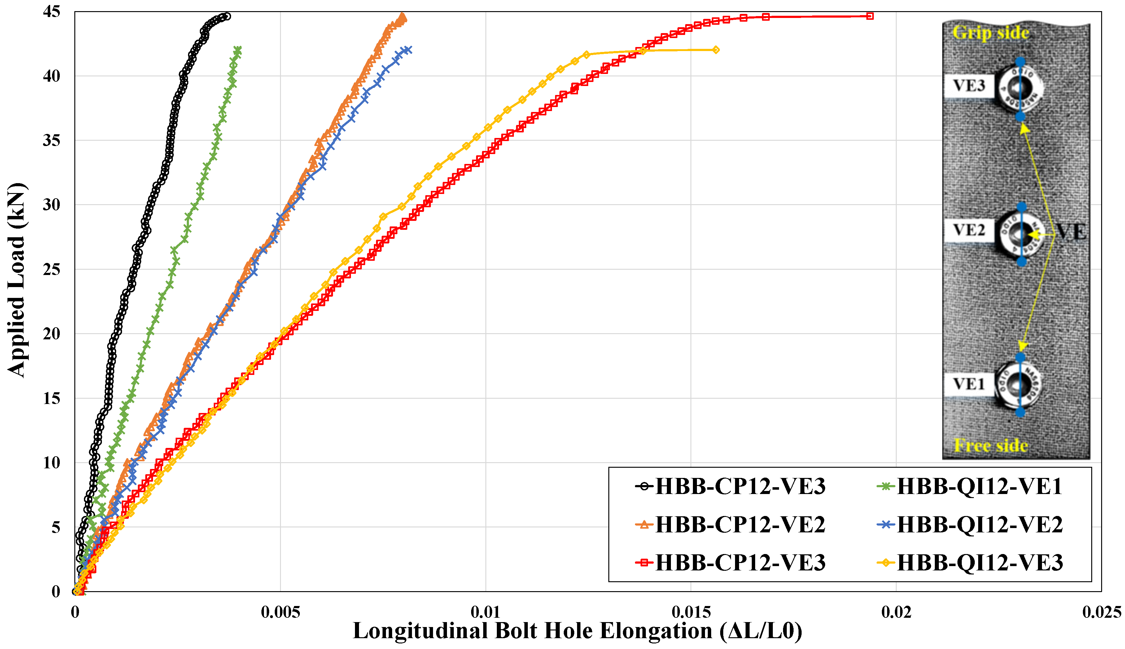
3.2.2. BHE of Hybrid-Bolted-Bonded (HBB) Joints

Figure 12 shows that for HBB joints, similarly to OB joints, BHE decreases when moving from B3 to B1. It is important to highlight that among the two main factors that contribute to hole elongation in SL bolted joints, the bypass load plays the predominant role in the HBB joints, as the added adhesive cancels out the bearing effect to a substantial extent [3]. Unlike the OB joints, in which bearing action is actively operative and alters the BHE (Figure 10), the curves of HBB remained mostly straight, which indicates minor changes in BHE stiffness throughout the test (Figure 12). This suggests that hybridization effectively eliminates the effects of stress concentration and notch sensitivity, which are noticeably influenced by the bearing act, in OB composite joints. It should be noted that since 12-layer laminate is stiffer than 8-layer laminate, the BHE stiffness (curve slope) of each hole of the former is greater than that of the latter (see Appendix A for the corresponding figure of 12-layer joints).
It is striking to underline that the BHE values of each peer-to-peer hole of CP and QI are almost equal for both 8 and 12 layers, which clearly indicates the independence of BHE from the laminate stacking sequence and bolt movement in the HBB SL composite joints studied herein. Furthermore, as there is no fair share of bearing acting in forming the hole elongation, it can be inferred that in multi-bolted hybrid composite joints, the dominant mechanism of load transmission between the two joint members is driven by the adhesive itself to a significant extent. Similar to Figure 11, the surface deformations under B3 for CP and QI are shown in Figure 13. It can be observed that the curves do not cross each other, and the concavity shape (depression) is formed merely by the bypass load [3], which flows around the hole and is the main contributor to the hole elongation development of HBB joints.

3.2.3. BHE in OB versus HBB: CP and QI

Figure 14 compares the BHE for OB and HBB joints with investigated laminates of eight layers. The load level (15 kN) corresponds to the onset of bearing damage in the OB joints, as shown in Figure 8. Therefore, the hole elongation values of CP are greater than those of QI, as was observed previously at higher load stages. Moreover, for a given thickness, the elongations of each hole of CP and QI, for example, bolt-hole 2 (BH2), are approximately identical in the HBB joint, whereas they markedly differ in the OB joint. This may suggest that hybridization significantly eliminates the hole elongation caused by the bearing effect, which is due to the bolt movement/tilting in OB configurations. According to Figure 14, hybridization decreases hole elongation, especially in the critical bolt (B3), and this decrease is more pronounced for CP than for QI. This occurred because, in comparison with QI, CP experiences a more severe stress concentration and notch sensitivity around the holes, and the added adhesive relieves it significantly. With the better performance of the adhesive in creating a dramatic reduction in the BHE of CP, the adhesive assists this configuration to substantially sustain its strength, as shown in Figure 7.

4. Conclusions

This study focused on highlighting the use of DIC to properly monitor hole elongation in woven laminated composites. DIC hole elongation was measured in the following carbon/epoxy composite sample configurations: standard open-hole tensile (OHT) and filled-hole tensile (FHT) specimens; single-lap shear only-bolted joint (OB); and single-lap shear hybrid-bolted-bonded joint (HBB).
In the case of OHT, for a given stress level, the total displacement of the specimen between grips was lower for CP than for QI laminates, and this behavior appears logical because CP is stiffer than QI. However, during the same tests, the longitudinal hole elongation (LHE) was higher for CP than for QI laminates, implying that the total displacement cannot indicate the state of deformation of the hole. During the same tests, the transverse hole compression (contraction) was measured, and against expectations, QI retracted more than CP. In other words, for CP, the hole elongated more than for QI but retracted less. The fact that the retraction was less for CP can be explained by the inherently lower Poisson’s ratio (νxy) of CP compared to QI. However, the mechanism underlying the higher LHE in CP is unclear. It must be noted that the aforementioned behavior was verified for two different laminate thicknesses. Asserting that the hole elongates more but retracts less for CP as compared to QI amounts to stating that the effective diameter of the hole increases in the case of CP, which explains the greater sensitivity to the notch of CP reported in the literature. The same behavior was observed for the case of FHT, except that the difference in LHE between CP and QI was observed only at high stress levels.
The same pattern behavior of FHT was replicated with multi-bolted OB joints, although some specific features emerged due to the fact that in multi-bolted OB, the load sharing between the three bolts increases when moving from the free end to the grip end. Bolt B3 at the grip end, which experienced the highest load, initially behaved similarly in CP and QI, but at approximately 40% of the ultimate load, the elongation of the bolt hole in CP increased at a greater rate than for QI. Moreover, it was found that in multi-bolted SL composite joints, the influence of the bypass load was greater than the bearing action in forming the hole elongation.
BHE was considerably lower in HBB than in OB. In fact, the results showed that the studied CP and QI laminates behave similarly until the onset of failure. The BHE of bolt B3 in CP surpassed that in QI, and the same was observed for bolt B2. Furthermore, hybridization significantly reduced BHE, which was more pronounced in CP than in QI. This is due to the effective stress concentration relief that occurred around the CP bolt hole because of the adhesive. Hybridization also aids in sustaining the strength of the HBB-CP joints.

Author Contributions

M.M.: investigation, conceptualization, methodology, formal analysis, writing—original draft preparation, visualization, and validation. A.L.J.: investigation, conceptualization, methodology, formal analysis, writing—original draft preparation, visualization, and validation. R.B.: supervision, writing—review and editing, project administration, funding acquisition, formal analysis, data curation, and resources. All authors have read and agreed to the published version of the manuscript.

Funding

The authors gratefully acknowledge the financial support provided by the Natural Sciences and Engineering Research Council of Canada (NSERC) number RGPIN-2022-04155.

Data Availability Statement

Data is contained within the article.

Conflicts of Interest

The authors declare no conflicts of interest.

Appendix A

For the sake of brevity in the manuscript, in the case of observing the same trend between the two different thicknesses, just one is reported, and readers are asked to refer to Appendix A. In this section, all those missing figures are brought up to help readers study them and make comparisons wherever required.
Figure A1 shows the bolt-hole elongation of only-bolted (OB) joints of cross-ply (CP) and quasi-isotropic (QI) lay-up with eight layers. The corresponding figure for 12 layers is illustrated in Figure 10 of the manuscript.
Figure A1. Bolt-hole elongation of OB-CP8 and OB-QI8.
Jcs 08 00180 g0a1
Figure A2 shows longitudinal deformation below B3 at 10%, 30%, 50%, 70%, and 90% of the applied load for only-bolted cross-ply (CP) and quasi-isotropic (QI) lay-ups with 12 layers. The corresponding figure for the eight layers is illustrated in Figure 11 of the manuscript.
Figure A2. Longitudinal deformation below B3 at 10%, 30%, 50%, 70%, and 90% of the applied load: (a) OB-CP12 and (b) OB-QI12.
Jcs 08 00180 g0a2
Figure A3 shows the bolt-hole elongation of hybrid-bolted-bonded (HBB) joints of cross-ply (CP) and quasi-isotropic (QI) lay-up with 12 layers. The corresponding figure for the eight layers is illustrated in Figure 12 of the manuscript.
Figure A3. Bolt-hole elongation of HBB-CP12 and HBB-QI12.
Jcs 08 00180 g0a3
Figure A4 shows longitudinal deformation below B3 at 10%, 30%, 50%, 70%, and 90% of the applied load for hybrid-bolted-bonded cross-ply (CP) and quasi-isotropic (QI) lay-up with 12 layers. The corresponding figure for the eight layers is illustrated in Figure 13 of the manuscript.
Figure A4. Longitudinal deformation below B3 at 10%, 30%, 50%, 70%, and 90% of the applied load: (a) HBB-CP12 and (b) HBB-QI12.
Jcs 08 00180 g0a4
Figure A5 compares BHE for only-bolted and hybrid-bolted-bonded laminates of 12 layers. The load level (25 kN) corresponds to the onset of bearing damage in only-bolted joints. The corresponding figure for the eight layers is illustrated in Figure 14 of the manuscript.
Figure A5. Comparison of BHE in OB12 versus HBB12 of CP and QI joints at a certain load level of 25 kN.
Jcs 08 00180 g0a5

References

  1. Caldwell, S.P.; Radford, D.W. Composite Single Lap Shear Joint Integrity Monitoring via Embedded Electromechanical Impedance Sensors. J. Compos. Sci. 2023, 7, 53. [Google Scholar] [CrossRef]
  2. Joy Mathavan, J.; Hassan, M.H.; Xu, J.; Franz, G. Hole Quality Observation in Single-Shot Drilling of CFRP/Al7075-T6 Composite Metal Stacks Using Customized Twist Drill Design. J. Compos. Sci. 2022, 6, 378. [Google Scholar] [CrossRef]
  3. Mehrabian, M.; Boukhili, R. 3D-DIC strain field measurements in bolted and hybrid bolted-bonded joints of woven carbon-epoxy composites. Compos. Part B Eng. 2021, 218, 108875. [Google Scholar] [CrossRef]
  4. Vangrimde, B.; Boukhili, R. Analysis of the bearing response test for polymer matrix composite laminates: Bearing stiffness measurement and simulation. Compos. Struct. 2002, 56, 359–374. [Google Scholar] [CrossRef]
  5. Sawicki, A.J.; Minguet, P.J. Failure mechanisms in compression-loaded composite laminates containing open and filled holes. J. Reinf. Plast. Compos. 1999, 18, 1708–1728. [Google Scholar] [CrossRef]
  6. Sola, C.; Castanié, B.; Michel, L.; Lachaud, F.; Delabie, A.; Mermoz, E. Bearing fatigue of composite laminates: Damage monitoring and fatigue life prediction. Compos. Part B Eng. 2017, 110, 487–496. [Google Scholar] [CrossRef]
  7. Saleh, M.N.; Wang, Y.; Yudhanto, A.; Joesbury, A.; Potluri, P.; Lubineau, G.; Soutis, C. Investigating the potential of using off-Axis 3D woven composites in composite joints’ applications. Appl. Compos. Mater. 2017, 24, 377–396. [Google Scholar] [CrossRef]
  8. Hu, J.; Zhang, K.; Cheng, H.; Liu, P.; Zou, P.; Song, D. Stress analysis and damage evolution in individual plies of notched composite laminates subjected to in-plane loads. Chin. J. Aeronaut. 2017, 30, 447–460. [Google Scholar] [CrossRef]
  9. Chen, H.-S. The static and fatigue strength of bolted joints in composites with hygrothermal cycling. Compos. Struct. 2001, 52, 295–306. [Google Scholar] [CrossRef]
  10. Starikov, R.; Schön, J. Fatigue resistance of composite joints with countersunk composite and metal fasteners. Int. J. Fatigue 2002, 24, 39–47. [Google Scholar] [CrossRef]
  11. Starikov, R.; Schön, J. Quasi-static behaviour of composite joints with protruding-head bolts. Compos. Struct. 2001, 51, 411–425. [Google Scholar] [CrossRef]
  12. Girard, C.; Dano, M.-L.; Picard, A.; Gendron, G. Bearing behavior of mechanically fastened joints in composite laminates—Part I: Strength and local strains. Mech. Adv. Mater. Struct. 2003, 10, 1–21. [Google Scholar] [CrossRef]
  13. Lawlor, V.P.; Mccarthy, M.A.; Stanley, W. An experimental study of bolt–hole clearance effects in double-lap, multi-bolt composite joints. Compos. Struct. 2005, 71, 176–190. [Google Scholar] [CrossRef]
  14. Subramanian, C.; Senthilvelan, S. Effect of reinforced fiber length on the joint performance of thermoplastic leaf spring. Mater. Des. 2010, 31, 3733–3741. [Google Scholar] [CrossRef]
  15. Wei, J.; Jiao, G.; Jia, P.; Huang, T. The effect of interference fit size on the fatigue life of bolted joints in composite laminates. Compos. Part B Eng. 2013, 53, 62–68. [Google Scholar] [CrossRef]
  16. Li, J.; Zhang, K.; Li, Y.; Liu, P.; Xia, J. Influence of interference-fit size on bearing fatigue response of single-lap carbon fiber reinforced polymer/Ti alloy bolted joints. Tribol. Int. 2016, 93, 151–162. [Google Scholar] [CrossRef]
  17. Nezhad, H.Y.; Egan, B.; Merwick, F.; McCarthy, C.T. Bearing damage characteristics of fibre-reinforced countersunk composite bolted joints subjected to quasi-static shear loading. Compos. Struct. 2017, 166, 184–192. [Google Scholar] [CrossRef]
  18. Giannopoulos, I.K.; Doroni-Dawes, D.; Kourousis, K.I.; Yasaee, M. Effects of bolt torque tightening on the strength and fatigue life of airframe FRP laminate bolted joints. Compos. Part B Eng. 2017, 125, 19–26. [Google Scholar] [CrossRef]
  19. Liu, F.; Lu, X.; Zhao, L.; Zhang, J.; Hu, N.; Xu, J. An interpretation of the load distributions in highly torqued single-lap composite bolted joints with bolt-hole clearances. Compos. Part B Eng. 2018, 138, 194–205. [Google Scholar] [CrossRef]
  20. Zhang, K.; Li, H.; Cheng, H.; Luo, B.; Liu, P. Combined effects of seawater ageing and fatigue loading on the bearing performance and failure mechanism of CFRP/CFRP single-lap bolted joints. Compos. Struct. 2020, 234, 111677. [Google Scholar] [CrossRef]
  21. Sajid, Z.; Karuppanan, S.; Sallih, N.; Kee, K.; Shah, S. Role of washer size in mitigating adverse effects of bolt-hole clearance in a single-lap, single-bolt basalt composite joint. Compos. Struct. 2021, 266, 113802. [Google Scholar] [CrossRef]
  22. Torres-Arellano, M.; Bolom-Martínez, M.d.J.; Franco-Urquiza, E.A.; Pérez-Mora, R.; Jiménez-Arévalo, O.A.; Olivier, P. Bearing Strength and Failure Mechanisms of Riveted Woven Carbon Composite Joints. Aerospace 2021, 8, 105. [Google Scholar] [CrossRef]
  23. Cao, Y.; Zuo, D.; Zhao, Y.; Cao, Z.; Zhi, J.; Zheng, G.; Tay, T.E. Experimental investigation on bearing behavior and failure mechanism of double-lap thin-ply composite bolted joints. Compos. Struct. 2021, 261, 113565. [Google Scholar] [CrossRef]
  24. Gamdani, F.; Boukhili, R.; Vadean, A. Tensile behavior of hybrid multi-bolted/bonded joints in composite laminates. Int. J. Adhes. Adhes. 2019, 95, 102426. [Google Scholar] [CrossRef]
  25. ASTM D3039/D3039M-14; Standard Test Method for Tensile Properties of Polymer Matrix Composite Materials. ASTM International: West Conshohocken, PA, USA, 2014.
  26. ASTM D5766-D5766M-11; Standard Test Method for Open-hole Tensile Strength of Polymer Matrix Composite Laminates. ASTM International: West Conshohocken, PA, USA, 2011.
  27. ASTM-D6742/D6742M-12; Standard Practice for Filled-Hole Tension and Compression Testing of Polymer Matrix Composite Laminates. ASTM International: West Conshohocken, PA, USA, 2012.
  28. ASTM-D5961/D5961M-13; Standard Test Method for Bearing Response of Polymer Matrix Composite Laminates. ASTM International: West Conshohocken, PA, USA, 2013.
  29. Gamdani, F.; Boukhili, R.; Vadean, A. Fatigue behavior of hybrid multi-bolted-bonded single-lap joints in woven composite plates. Int. J. Fatigue 2022, 158, 106738. [Google Scholar] [CrossRef]
  30. Gamdani, F.; Boukhili, R.; Vadean, A. Tensile strength of open-hole, pin-loaded and multi-bolted single-lap joints in woven composite plates. Mater. Des. 2015, 88, 702–712. [Google Scholar] [CrossRef]
  31. Tomblin, J.; Seneviratne, W. Laminate Statistical Allowable Generation for Fiber-Reinforced Composite Materials: Lamina Variability Method; Office of Aviation Research and Development, Federal Aviation Administration, Department of Aerospace Engineering, Wichita State University: Wichita, KS, USA, 2009. [Google Scholar]
  32. Portanova, M.A.; Masters, J. Standard Methods for Filled Hole Tension Testing of Textile Composites; NASA Contractor Report; Lockheed Martin Engineering and Sciences Company: Hampton, VA, USA, 1995; p. 198263. [Google Scholar]
  33. Lim, J.B.; Nethercot, D. Stiffness prediction for bolted moment-connections between cold-formed steel members. J. Constr. Steel Res. 2004, 60, 85–107. [Google Scholar] [CrossRef]
  34. Mehrabian, M.; Boukhili, R. Quantifying of secondary bending effect in multi-bolt single-lap carbon-epoxy composite joints via 3D-DIC. Compos. Sci. Technol. 2020, 200, 108453. [Google Scholar] [CrossRef]
  35. Skorupa, A.; Skorupa, M. Differences between the Fatigue Behaviour of Longitudinal Lap Joints in a Pressurized Fuselage and Laboratory Lap Joint Specimens; Riveted Lap Joints in Aircraft Fuselage; Springer: Berlin/Heidelberg, Germany, 2012; pp. 11–26. [Google Scholar]
Figure 1. Specimen geometry and dimensions: (a) OHT joints; and (b) OB and HBB SL joints.
Jcs 08 00180 g001
Figure 2. Application of virtual extensometers in Vic-3D: (a) OHT and (b) FHT.
Jcs 08 00180 g002
Figure 3. Effect of laminate configuration on open- and filled-hole notch deformation: (a) OHT with LHE; and (b) FHT with LHE.
Jcs 08 00180 g003
Figure 4. Load–displacement curves of CP8, CP12, QI8, and QI12: (a) OHT and (b) FHT.
Jcs 08 00180 g004
Figure 5. The effect of laminate configuration on open- and filled-hole notch deformation: (a) OHT with THC; and (b) FHT with THC.
Jcs 08 00180 g005
Figure 6. Strain contours at 40% of the failure load for longitudinal strains of (a) CP12 and (b) QI12, as well as transversal strains of (c) CP12 and (d) QI12.
Jcs 08 00180 g006
Figure 7. Failure loads of CP and QI with 8 and 12 layers: (a) HBB and (b) OB.
Jcs 08 00180 g007
Figure 8. Load–displacement curves with the indication of bearing zone onset of OB vs. HBB joints: (a) CP8, (b) CP12, (c) QI8, and (d) QI12.
Jcs 08 00180 g008
Figure 9. (a) An exaggerated schematic of the BHE in an SL joint; and (b) the placement of three VEs at the hole position in DIC software.
Jcs 08 00180 g009
Figure 10. Bolt-hole elongation of OB-CP12 and OB-QI12 (the same pattern occurs for eight layers; see Appendix A).
Jcs 08 00180 g010
Figure 11. Longitudinal deformation below B3 at 10%, 30%, 50%, 70%, and 90% of the failure load: (a) OB-CP8 and (b) OB-QI8 (the same pattern occurs for 12 layers; see Appendix A).
Jcs 08 00180 g011
Figure 12. BHE of HBB-CP8 and HBB-QI8 (the same pattern occurs for 12 layers; see Appendix A).
Jcs 08 00180 g012
Figure 13. Longitudinal deformation below B3 at 10%, 30%, 50%, 70%, and 90% of the failure load: (a) HBB-CP8 and (b) HBB-QI8 (the same pattern occurs for 12 layers; see Appendix A).
Jcs 08 00180 g013
Figure 14. Comparison of BHE in OB8 versus HBB8 of CP and QI joints at a load level of 15 kN (the same pattern occurs for 12 layers; see Appendix A).
Jcs 08 00180 g014
Table 1. Stacking sequences and tensile strengths of the unnotched (TS), open-hole (OHT), and filled-hole (FHT) configurations of the manufactured laminates. The value of the standard deviation (STD) is given between brackets.
CodeLay-upPliesAverage Thickness, t mm,Unnotched, TS MPa,
(STD)
Open-Hole, OHT MPa,
(STD)
Filled-Hole, FHT MPa,
(STD)
CP8[(0/90)/(0/90)/(0/90)/(0/90)]s81.65854
(29.80)
455
(9.82)
420
(0.95)
QI8[(0/90)/(±45)/(0/90)/(±45)]s8592
(9.12)
384
(6.76)
366
(0.30)
CP12[(0/90)/(0/90)/(0/90)/(0/90)/(0/90)/(0/90)]s122.63800
(15.26)
406
(8.40)
442
(1.03)
QI12[(0/90)/(±45)/(0/90)/(±45)/(0/90)/(±45)]s12579
(9.00)
364
(7.98)
358
(1.18)
Disclaimer/Publisher’s Note: The statements, opinions and data contained in all publications are solely those of the individual author(s) and contributor(s) and not of MDPI and/or the editor(s). MDPI and/or the editor(s) disclaim responsibility for any injury to people or property resulting from any ideas, methods, instructions or products referred to in the content.

