Article

Multiscale Modeling of Elastic Waves in Carbon-Nanotube-Based Composite Membranes

by
Elaf N. Mahrous
1,
Muhammad A. Hawwa
2,*,
Abba A. Abubakar
2 and
Hussain M. Al-Qahtani
2
1
Department of Mechanical Engineering, Jubail Industrial College, Jubail Industrial City 31961, Saudi Arabia
2
Department of Mechanical Engineering and IRC for Advanced Materials, King Fahd University of Petroleum & Minerals, Dhahran 31261, Saudi Arabia
*
Author to whom correspondence should be addressed.
J. Compos. Sci. 2024, 8(7), 258; https://doi.org/10.3390/jcs8070258
Submission received: 24 May 2024 / Revised: 15 June 2024 / Accepted: 21 June 2024 / Published: 3 July 2024
(This article belongs to the Special Issue Theoretical and Computational Investigation on Composite Materials)

Abstract

:
A multiscale model is developed for vertically aligned carbon nanotube (CNT)-based membranes that are made for water purification or gas separation. As a consequence of driving fluids through the membranes, they carry stress waves along the fiber direction. Hence, a continuum mixture theory is established for a representative volume element to characterize guided waves propagating in a periodically CNT-reinforced matrix material. The obtained coupled governing equations for the CNT-based composite are found to retain the integrity of the wave propagation phenomenon in each constituent, while allowing them to coexist under analytically derived multiscale interaction parameters. The influence of the mesoscale characteristics on the continuum behavior of the composite is demonstrated by dispersion curves of harmonic wave propagation. Analytically established continuum mixture theory for the CNT-based composite is strengthened by numerical simulations conducted in COMSOL for visualizing mode shapes and wave propagation patterns.

1. Introduction

1.1. Motivation

With the advent of carbon nanotube (CNT)-based membranes for water purification as well as for gas separation systems [1,2,3], a new class of nanocomposites came to light. Membranes with vertically aligned carbon nanotubes, which are perpendicular to the membrane surfaces, have been developed to facilitate fluid flow and exploit unique nanofluidic characteristics, such as the particles’ large surface area and Brownian motion. From a structural dynamics perspective, one can regard the CNT-based membrane as a composite structure with matrix material hosting hollow nanofibers. This nanocomposite is expected to carry stress waves along the fiber direction as a result to driving fluids through the membrane. As any structure exposed to dynamic loading, it is important to learn its dynamic characteristics when it is free of imperfections, to record its “signature”, which is used as a reference; then, it becomes easy to check its operational condition if it has any defects. In such a way, this work aimed to gain an understanding of the wave propagation characteristics of these CNT-based composite structures.

1.2. CNT-Reinforced Composites

When conducting a literature search on CNT-based composites, we found that researchers have been proposing the use of CNT-reinforced composites to create highly strong materials [3,4]. Since carbon nanotubes (CNTs) are approximately thirty times stronger than steel and five times less dense, they are ideal candidates to be used as reinforcing fibers. Hence, if CNT-fiber reinforced composites are manufactured “right”, i.e., with a suitable fiber distribution and alignment, they are expected to form lightweight, super strong materials. In order to estimate the properties and predict the behavior of CNT-reinforced composites, researchers have spent time conducting delicate experiments to measure load transfer and deformation mechanisms in carbon nanotube–polystyrene composites [5], investigate the detachment of carbon nanotubes from a polymer matrix [6], estimate the mechanical and electrical properties of CNT/epoxy composites [7], evaluate the carbon nanotube–polymer interfacial strength [8], and measure the bending strength and fracture toughness of CNT-reinforced alumina composites [9].
Since experiments at the nano level are quite elaborate and molecular dynamic (MD) simulations are computationally involved [10,11], continuum mechanics models have been proven to establish a link between experimental/computational molecular chemistry and solid mechanics [12]. Research groups have designed constitutive models for two types of CNT–polyimide composite structures [13] and built a model that accounted for CNT reinforcement geometry, to show the sensitivity of elastic properties to the nanotube diameter and volume fraction in composites [14].
Various continuum approaches based on representative volume elements (RVEs) were proposed to express the interaction of CNT “fibers” with the surrounding matrix. Liu et al. [15] used a finite element approach on a three-dimensional nanoscale RVE to evaluate the effective mechanical properties of CNT-based composites. Karimzadeh et al. [16] applied a finite element method using two-dimensional axisymmetric and three-dimensional square RVEs to predict the mechanical behavior of CNT-reinforced polymers. Tserpes et al. [17] proposed an RVE to be used to study the tensile behavior of a unidirectional nanotube/polymer composite and compared the results with corresponding rule-of-mixture predictions. Meguid et al. [18] employed an energy approach on atomistic-based RVEs to characterize the behavior of CNT-reinforced amorphous epoxies. Montazeri and Naghdabadi [19] utilized a multiscale modeling procedure to investigate the interfacial effects on the Young’s modulus of CNT/polymer composites and compared the results with MD simulations. Ayatollahi et al. [20] considered a CNT-reinforced composite under tensile, bending, and torsional loading conditions, proposing an equivalent beam element for evaluating the nanocomposite stiffness. García-Macías et al. [21] utilized a homogenization approach to model CNT-reinforced polymers, focusing on the sensitivity of the macroscopic response to microstructural properties including the filler volume fraction, chirality, and aspect ratio. For a recent reference on basic approaches for analyzing multiscale hybrid nanocomposites, the reader is referred to the book by Ebrahimi and Dabbagh [22].

1.3. Dynamic Modeling of CNT-Based Composites

Given the importance of developing nanomechanical oscillators/resonators, dynamic characterization of nanocomposites has attracted special attention, with value for estimating resonant frequencies and vibration modes. Continuum approaches have been utilized to calculate resonant frequencies and associated vibrational modes of nanocomposites with embedded CVTs and assess vibration damping characteristics in CNT-epoxy-reinforced composites. For a review on vibrations of CNT-based composites, the reader is referred to the paper by Gibson et al. [23]. The recent trend in the continuum approach of CNT-reinforced composites is to apply numerical models on RVEs. A demonstrative paper in this direction was published by Palacios and Ganesan [24], who implemented an RVE-based finite element study on the dynamic response of a CNT-reinforced polymer to determine the natural frequencies and damping properties, and established a relationship between the damping ratio and natural frequencies.
Since the CNT diameter–length ratios are very small, researchers prefer to consider the dynamic behaviors of nanocomposites within the context of wave propagation. Natsuki et al. [25] studied flexural symmetrical and asymmetrical modes of nanotubes embedded in an elastic matrix, treating the CNT surrounding medium as a Winkler material, and identified the different wave characteristics of single- and double-walled CNT-reinforced elastic medium. Mitra and Gopalakrishnan [26] considered waves propagating in an RVE, taking the geometry of a shear deformable beam with a square cross-section. Using a wavelet solution, they predicted the transfer of shear stress between the CNT fibers and the surrounding matrix due to terahertz-frequency elastic waves. Alavinasab et al. [27] studied CNT-based composites within the framework of nonlocal elasticity and found that the dispersion curve of plain waves was close to that obtained using the atomic Born–von Karman model. Ebrahimi et al. [28] considered higher-order flexural wave propagation in a polymeric composite plate that is reinforced by a combination of glass fibers and carbon nanotubes, and investigated the influence of fibers’ arrangements on wave dispersion characteristics. They found that waves in hybrid nanocomposites can propagate at higher wave frequencies than those propagating in other types of composites. Since the authors of these publications were motivated to propose high-strength CNT-reinforced composite structural components, they focused on flexural and shear waves that are normally encountered in these composite elements.

1.4. Problem Statement and Solution Methodology

As the current study was performed primarily to model the dynamic behavior of CNT-based membranes that are employed in water purification and gas separation systems, our attention was on modeling the propagation of axisymmetric longitudinal elastic waves in a CNT-based composite membrane, since these are the types of waves generated due to the fluid pumping effect through the membrane. Hence, a continuum mixture model was established to model the dynamic behavior of a CNT-based composite with an RVE that had a hexagonal cross-section. As this was the first work focusing on CNT-based membrane dynamics, we applied a rigorous analytical method to tackle the problem. An area averaging approach for building a continuum mixture theory was utilized. This method was proven effective in studying elastic, electromagnetic, piezoelectric, and thermoelastic waves and heat conduction in composites by Nayfeh et al. [29,30,31,32,33,34]. In this study, a continuum mixture theory was developed for longitudinal elastic waves along the CNT direction, as described in Section 2. Interesting is looking at the nanostructured composite as a matrix hosting hollow fibers; in this way, one can consider the nanocomposite as a three-phase medium. Our analytical study was further supplemented by numerical simulations conducted in COMSOL to visualize mode shapes and wave propagation patterns. The results obtained from the unique mixture model in the form of the dispersion relationship of propagating elastic modes, and numerically obtained mode shapes, are presented and discussed in Section 3. The work is concluded in Section 4.

2. Mathematical Modeling and Numerical Simulation

The composite structure under consideration was inspired by using membranes hosting arrays of carbon nanotubes to act as filters for water desalination or purification, or as membranes for separating different gas molecules. In both applications, some fluid runs through the nanotubes and some other fluid(s) cannot pass through due to the size(s) of its molecules, as shown schematically in Figure 1. In all cases, the membrane can be regarded as a small-sized composite structure composed of a matrix material that embraces hollow nanofibers. Due to the “pumping effect” of the fluid, stress waves propagate in the direction along the fibers. Multiscale modeling is adopted to gain an understanding of the wave propagation characteristics of the composite structure. The analysis aims at describing a system’s behavior on one level using information from different levels, where appropriate methodologies are applied on each level.

2.1. Mathematical Modeling

Let us start with fundamental assumptions: Under investigation is a composite structure composed of a matrix embracing periodically distributed CNTs as fibers. The manufacturing of composites with vertically aligned CNTs is nowadays a maturing technology [35]. Thus, the CNT-based composite with an appropriate distribution and alignment of nanotubes can be considered a unidirectionally reinforced periodic composite, as shown in Figure 2. It is assumed that the matrix maintains a homogeneous structure throughout the material and that the CNT fibers are directly incorporated into the matrix material; thus, the CNT/matrix interface is fully bonded. The assumption of perfect interfacial bonding of the CNT to the host matrix seems to be ambitious. However, recent techniques for improving interfacial shear strength have been presented. Examples include the work of Park et al. [36], who showed the formation of good covalent bonding between Al and CNT when considering the formation of Al4C3 sub-elements; the computational study of Norouzi et al. [37], on strengthening the CNT/matrix interfacial bond, which showed this was possible when the aspect ratio of CNT fibers was increased [36]; and the review presented by Hashim et al. [38] on the interfacial bonding of CNT reinforcement of aluminum matrix composites. The cores of CNT fibers are assumed to be continually filled with air or water.
For the case of CNT-based composites, two levels can be identified: (i) mesoscale (or nano-level) information including information about groups of molecules is included; and (ii) continuum-level models. Thus, the continuum prediction of composite behavior is based on knowledge of carbon nanotubes’ mechanical properties.

2.1.1. Representative Volume Element

The CNT-based composite has a hexagonal symmetry with a representative volume element, as shown in Figure 3. In order to facilitate the analysis, the RVE may be approximated by concentric cylinders, as shown in the same figure, where the RVE has an outer radius r 2 while the single-walled CNT fiber has an outer radius r 1 and an inner radius r 0 . The use of an RVE in the form of a circular cylinder instead of a hexagonal cylinder is solely based on making the problem amenable to analytical treatment. The validity of using an approximate RVE is yet to be checked, as covered in Section 2.2 using the finite element method.
The following cylindrical coordinate momentum equations and constitutive relations can be written for each of the three constituents of the RVE (matrix, CNT, and filling) to describe the dynamic behavior in each individual component:
σ z z z + 1 r z r σ r z = ρ 2 u t 2
σ r r r + σ r z z + 1 r σ r r σ θ θ = ρ 2 v t 2
σ z z = C 11 u z + C 12 r r r v
σ r r = C 22 v r + C 12 r v + C 12 u z
σ θ θ = C 11 v r + C 12 v r + C 12 u z
σ r z = C 44 ( v z + u r )
where σ i j is the stress tensor, u and v are the displacement components in the longitudinal and radial directions of the RVE, and C i j is the stiffness coefficient. The two-dimensional field Equations (1)–(6) that hold in all RVE layers (the matrix, CNT, and filling) can be applied to define dynamic mixture equations by utilizing a geometric averaging process.

2.1.2. Averaging Process

The averaging process followed in this paper is based on converting a two-dimensional dynamic system of equations into a quasi-one-dimensional system of coupled partial differential equations, which retains the dynamics in individual constituents of the representative volume element while allowing them to coexist under interfacial interaction of the constituents. Inspired by the works of Nayfeh et al. [29,30,31,32,33,34], the equations of motion and the constitutive Equations (1)–(6) are subjected to the following area averaging:
( ) f ¯ = 1 π   r 0 2 0 r   2 π ( ) f   d r , ( ) c ¯ = 1 π   ( r 1 2 r 0 2 )   0 r   2 π ( ) c   d r ,   and ( ) m ¯ = 1 π   ( r 2 2 r 1 2 )   0 r   2 π   ( ) m   d r
where the subscripts f , c, and m are used to identify the filling, carbon nanotube, and matrix material, respectively. This leads to three systems of partial differential equations in the axial direction (z) and time.
Due to cylindrical symmetry, the radial displacements and shear stresses vanish at r = 0 and r = r 2 ; thus,
v f z , 0 , t = 0 ,   σ r z f z , 0 , t = 0 ,   v m z , r 2 , t = 0 ,   and σ r z m z , r 2 , t = 0
Interfacial continuity of radial displacements and shear stresses are intuitively realized at r = r 0 ; thus,
σ r z f z , r 0 , t = σ r z c z , r 0 , t , σ r f z , r 0 , t = σ r c z , r 0 , t , u f z , r 0 , t = u c z , r 0 , t ,   and   v f z , r 0 , t = v c z , r 0 , t
and at r = r 1 ; thus,
σ r z c z , r 1 , t = σ r z m z , r 1 , t , σ r c z , r 1 , t = σ r m z , r 1 , t , u c z , r 1 , t = u m z , r 1 , t ,   and   v c z , r 1 , t = v m z , r 1 , t
The “common” radial displacement and shear stress at the two interfaces are used to define four interaction (coupling) terms S 1 (= 2 n f v 1 * r 0 ) , S 2 (= 2 n f + n c v 2 * r 1 ) , ζ 1 (= 2 n f σ r z 1 * r 0 ) , and ζ 2 (= 2 [ ( n f ) + ( n c ) ] σ r z 2 * r 1 ) , where v 1 * , v 2 * , σ r z 1 * , and σ r z 2 * are the interface the radial displacement and shear stress at r 0 and r 1 , respectively; and n f (= r 0 2 r 2 2 ), n c ( = ( r 1 2 r 0 2 ) r 2 2 ), and n m ( = ( r 2 2 r 1 2 ) r 2 2 ) are the volume fractions of the fillings, carbon nanotube, and matrix, respectively.
In order to solve the interaction parameters in terms of averaged radial displacement and averaged shear stress, one can utilize the following approximate conditions: (i) neglect ( v z ) , and (ii) consider u and σ r z to be linearly dependent on r 29 . For a steady-state harmonic solution, assume
( u f ¯ , u c ¯ , u m ¯ , A 1 , A 2 , B 1 , B 2 ) = ( X 1 , X 2 , X 3 , X 4 , X 5 , X 6 , X 7 ) e i ( k z w t )
Then, derive the characteristic dispersion equation as the determinant of
[ M ] = n f ρ f ω 2 C 11 f k 2 0 0 2 n f 0 0 n c ρ c ω 2 C 11 c k 2 n c 0 2 n f 2 n c + n f 0 0 n m ρ m ω 2 k 2 C 11 m n m 0 2 n c + n f 4 C 55 f 4 C 55 f 0 r 0 2 4 C 55 f χ 1 4 C 55 f χ 2 0 2 C 55 m C 55 m C 55 m χ 1 χ 2 C 55 m χ 2 4 i C 12 f k 4 i C 12 c k 0 i k r 0 2 4 γ 5 b 4 i k γ 6 b 0 2 i C 12 c k i k C 12 m i k γ 5 b i k γ 6 b i k γ c 2 2 i C 12 f k n f 0 2 i C 12 c k n f 2 i C 12 c k n c + n f 0 2 i k C 12 m n c + n f i C 55 f k r 0 2 + 4 ψ 1 4 i C 55 f k ψ 2 i k C 55 m ψ 1 i k ψ 2 i k C 55 m ψ 2 ρ f r 0 2 + 4 γ 3 b ω 2 4 C 12 f + C 22 f + γ 1 b + δ 1 4 γ 4 b ω 2 + γ 2 b + δ 2 γ 3 b ω 2 + γ 1 b + 2 δ 1 γ 4 b ω 2 + γ c 3 ω 2 + γ 2 b γ c 1 + 2 δ 2 κ

2.2. Numerical Simulation

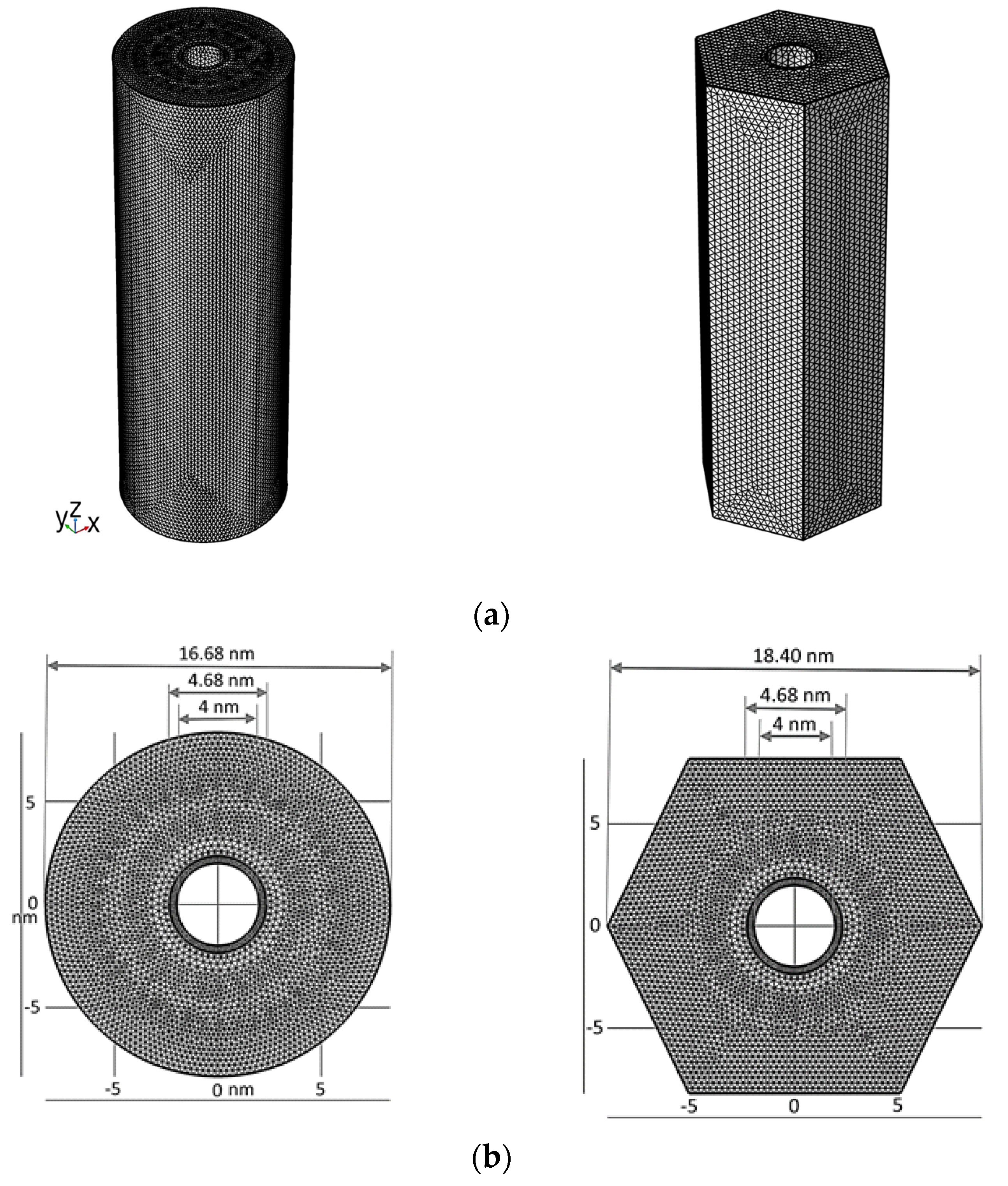
To verify the analytical model and confirm the influence of CNT reinforcement on the vibrational characteristics of the aggregate composite structure, three-dimensional (3D) finite element simulations are conducted. Eigenfrequency analysis is performed to predict the corresponding resonant frequencies of the CNT-based composite structure. Mode shapes are appropriately normalized so that the orthonormality condition is satisfied for each mode. The generalized equation of dynamic equilibrium, i.e., M 2 u t 2 + K u = 0 , governing the motion of free vibrations of the hexagonal cylindrical and the circular cylindrical RVE domains, is considered; here, u is the displacement vector, M is the mass matrix, and K is the stiffness matrix. For the free vibration of both hexagonal cylindrical and circular cylindrical RVEs, two generalized eigenvalue problems taking the general form of K ψ = ω 2 M ψ are solved to yield “ n eigensolutions for the mode shapes: ( ψ 1 , ω 1 2 ) , ( ψ 2 , ω 2 2 ) , ( ψ 3 , ω 3 2 ) , …, ( ψ n , ω n 2 ) , where ψ i is the i t h mode shape vector, and ω i is the i t h angular frequency, from which the i t h natural frequency is calculated, i.e., f i = ω i 2 π . The orthonormality criteria are satisfied for each mode by carefully normalizing the mode forms. The hexagonal cylindrical RVE with the dimensions 5 n m × 5 n m × 50 n m was used to perform the finite element simulation of the CNT-based composite in the multi-physics package COMSOL, incorporating the required initial and boundary conditions. The circular cylindrical RVE has the same cross-sectional area as that of the hexagonal cylindrical RVE. While it is feasible to host suitable fillings, the CNT fibers are assumed to be hollow with air-filled cores. The initial displacement and velocity vector elements are set to zero. Periodic boundary conditions are applied at the top and bottom of the faces of both RVEs to resemble infinitely long RVEs. Neumann boundary conditions are applied to the side faces of both RVEs. As assumed in the analytical formulation, perfect mechanical bonding is applied at the CNT–matrix interfaces. The elastic properties of the CNT and host matrix are imposed in their respective domains. The RVE is meshed with about 339,141 tetrahedral quadratic elements with an average quality of 0.7, as shown in Figure 4. To improve the accuracy of numerical solutions at the CNT–matrix interface, a higher mesh density is used around these boundary regions. To verify finite element solution convergence, the simulations are run for various element sizes. A converged solution is obtained with the 339,141 elements, a minimum element size of 0.5 nm, and a maximum of 300 iterations for the eigenproblem solver.

3. Results and Discussion

The dispersion relation that relates the wavenumber (k) and frequency (ω) is solved numerically as a complex transcendental equation to find the zeros of the determinant of Equation (12). Wave dispersion characteristics have been utilized as an efficient tool for the nondestructive evaluation of composite structures. Thus, from a practical view point, dispersion curves can be used to check the integrity of the CNT-based membrane.
As a first step, the problem was programmed for the case of the classical fiber-reinforced composite presented in reference [19], to establish confidence in the software code of the analytical results. Next, four representative cases of CNT-reinforced composites were considered: (A) a silicon carbide (SiC) matrix hosting (10,0) zigzag carbon nanotubes, (B) a SiC matrix hosting (12,6) chiral carbon nanotubes, (C) a titanium (Ti) matrix hosting (10,0) zigzag carbon nanotubes, and (D) a Ti matrix hosting (12,6) chiral carbon nanotubes. The SiC matrix material has a density of 3.2 g/c m 3 , and stiffness properties of C 11 m = 446 Gpa, C 12 m = 92 Gpa, and C 44 m = 177 Gpa. The Ti matrix material has a density of 5.4 g/c m 3 , and stiffness properties of C 11 m = 193 Gpa, C 12 m = 103 Gpa, and C 44 m = 45 Gpa.
A (10,0) zigzag carbon nanotube has a density of 1.34 g/c m 3 and a modulus of elasticity of 0.94 Tpa, while a (12,6) chiral carbon nanotube has a density of 1.40 g/c m 3 and a modulus of elasticity of 0.92 Tpa [36]. Poisson’s ratio is assumed to be 0.3 for both carbon nanotubes.
The RVE composite dimensional properties are r 0 = 2 nm, r 1 = 2.34 nm, and r 2 = 8.34 nm. The core parts of the carbon nanotubes are assumed to be filled with air. With this, the dispersion curves for the CNT-reinforced composites are constructed.
Figure 5 compares the dispersion curves for a (10,0) zigzag CNT-reinforced SiC matrix to those for a (12,6) chiral CNT-reinforced SiC matrix. The dispersion curves for the lowest five modes are given for each of the four representative composites. The curves are depicted in the phase speed–frequency plane.
At low frequencies, the lowest three modes of the zigzag-reinforced SiC matrix and chiral CNT-reinforced SiC matrix tend to be identical, while the higher two modes of each composite are well-distinguished from each other. The fundamental modes converge at the zero-frequency limits to the same effective mixture wave speed. The tendency of modes to converge to the bulk wave speeds at high frequencies is quite typical.
Figure 6 compares the dispersion curves for a (10,0) zigzag CNT-reinforced Ti matrix with those for a (12,6) chiral CNT-reinforced Ti matrix. The dispersion curves for the lowest five modes are given for each of the four representative composites. The curves are depicted in the phase speed–frequency plane. For the case of the zigzag CNT-reinforced Ti matrix and chiral CNT-reinforced Ti matrix, the modes of each composite are clearly differentiated from each other. Two distinct zero-frequency mixture wave speeds can be observed for the two composites. The modes, however, converge to the bulk wave speeds as the frequency increases.
It is thus shown in both Figure 5 and Figure 6 that the “nanostructures” of the carbon nanotubes play an important role in shaping the dispersion of longitudinally propagating waves. Continuum modeling based on averaging is attractive for use in preliminary engineering designs or early nondestructive evaluations. The dispersion curves shown in Figure 5 and Figure 6 are those for an intact CNT-based composite. If the composite geometry is altered such as in a case of fouling affecting the value of r 0 , for example, the dispersion curves would have different configurations, which indicates an inadequacy that lowers the performance effectiveness in accomplishing the function it is supposed to perform. Other factors that could be detected from deviations in the dispersion curves include chemical reactions that could change mechanical properties of the composite structure’s constituents.
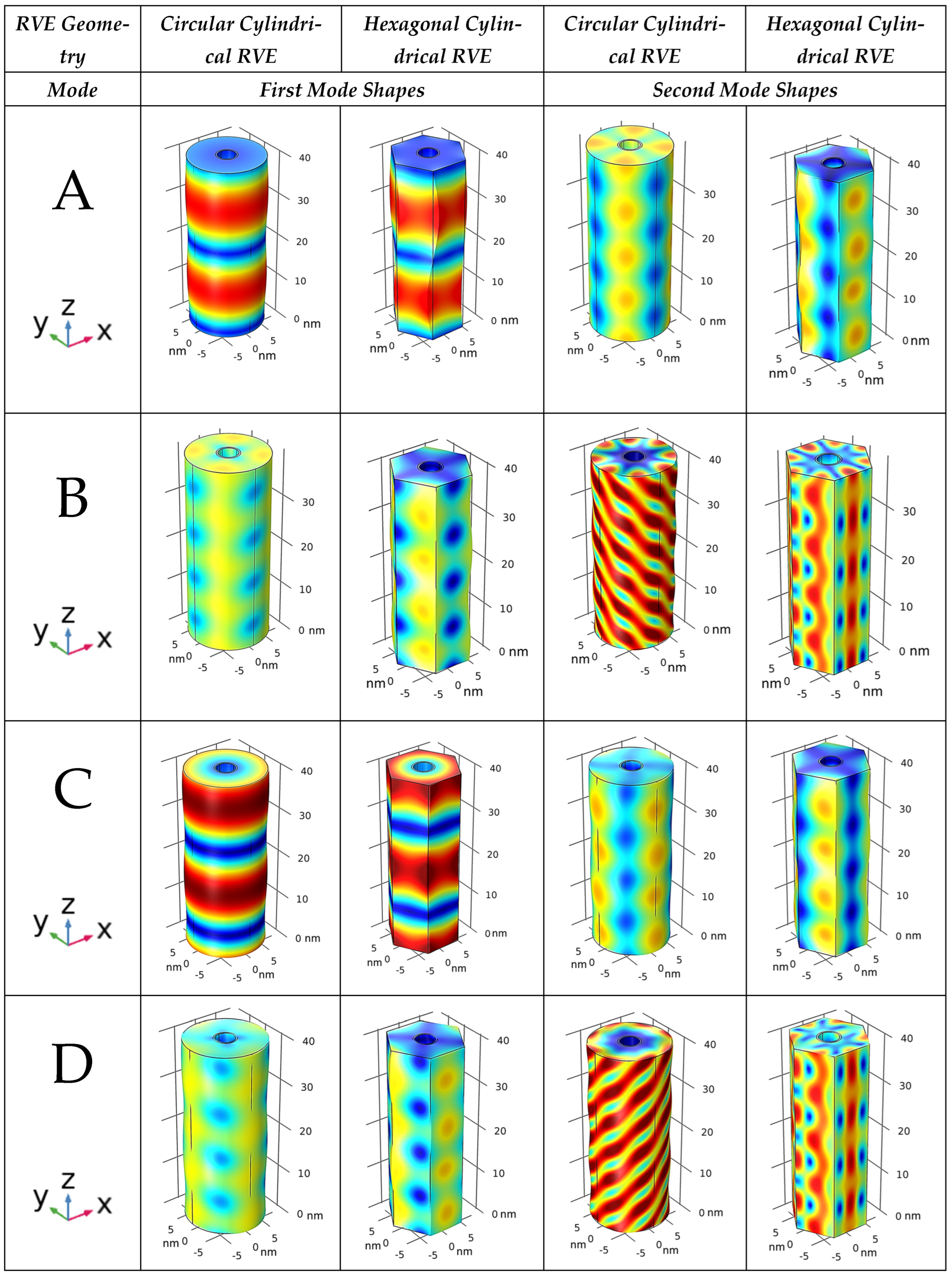
Numerical simulation results are shown in Figure 7, which illustrates the lowest two longitudinal vibrational mode shapes of the four RVE cases considered for the analytical modeling presented so far. Mass and stiffness are well-known factors that affect a structural object’s natural frequency. Whereas stiffer materials vibrate at higher frequencies, heavier objects vibrate at lower frequencies (Table 1).
It can be noted in Figure 7 that the first mode shape of the circular cylindrical RVE is very close to that of the hexagonal cylindrical RVE, while the second mode shape of the circular cylindrical RVE is somewhat close to that of the hexagonal cylindrical RVE. The investigation of the third and fourth mode shapes showed that mode shapes of the circular cylindrical RVE are notably different from their corresponding mode shapes of the hexagonal cylindrical RVE. Hence, the geometric approximation of the hexagonal cylindrical RVE to the circular cylindrical RVE, which has been used for obtaining the analytical dispersion relations, should be limited to deriving low-frequency information, and it should not be used for predicting high-frequency characterizations. The intriguing observation though is that the wave propagation along the CNT-based composite is affected by the characteristics of fiber reinforcement. The CNT “nanostructures” (zigzag or chiral formed) does play a clear role in determining the mode shape of the first two vibrational modes. In other words, numerical simulations indicate that the “reinforcing” carbon nanotubes play a significant role in how the composite RVE deforms when waves propagate through that RVE.
In the simulations performed, larger displacements were predicted for the CNT-reinforced SiC composite structure than the CNT-reinforced Ti composite. This was because SiC is almost twice as stiff as Ti, even though the density of Ti is close to 1.5 times less than that of SiC. Moreover, the vibrational mode shapes and displacement magnitudes were more greatly affected when the (10,0) zigzag CNT was replaced by the (12,6) chiral CNT in the SiC host matrix.
The mode shapes shown in Figure 7 are those for an intact CNT-based composite. If either the composite geometry, material properties, or both are altered in cases of fouling or chemical reactions, the natural frequencies and mode shapes will be different from those of the intact composite structure. Frequency and/or mode shape changes can indicate potential improper functioning of the composite membrane.
For future research works on unique CNT composite membranes, we recommend investigating (i) the effect of having a polymeric matrix and how intrinsic damping of the polymer will change dispersion and vibration characteristics; (ii) the effect of utilizing multi-walled CNTs for water purification or gas separation in a multiscale analysis of the composite membrane; (iii) the effect of including a heavier core material such as water in place of air on the dynamic properties of the composite structure; (vi) a more realistic model accounting for weak interfacial bonding, since the assumption of perfect CNT–matrix bonding with full load transfer is idealistic; (v) the effect of weakening matrix–fiber bonding, to understand whether this influences structural dynamic characteristics; and (iv) the effect of an imperfect CNT distribution and/or the effect of deviation of the CNT from being vertically oriented.

4. Conclusions

Carbon-nanotube-based membranes for water purification or gas separation were considered from a structural dynamics viewpoint. Hence, the propagation of longitudinal elastic waves in single-walled carbon nanotubes (SWNTs) embedded in a matrix was studied. The CNT-based composite was considered by focusing on a representative volume element made from a continuum axisymmetric cylinder building block, as an approximation of a hexagonal cylindrical element. Then, a continuum mixture model was established based on an analytical scheme that involves area averaging. Numerical illustrations were produced to study the axial wave propagation in an SWNT-reinforced elastic matrix in the terahertz range. Finite element simulations performed in COMSOL showed the mode shapes of circular cylindrical as well as hexagonal cylindrical RVEs for a composite membrane hosting zigzag as well as chiral CNTs. Both the analytical continuum model dispersion curves and the FEM-derived mode shapes indicated that the reinforcing CNT nanostructure had an effect on the higher-level behavior produced by the composite dynamic characteristics.

Author Contributions

Conceptualization, E.N.M. and M.A.H.; methodology, E.N.M. and M.A.H.; software, E.N.M.; validation, A.A.A. and H.M.A.-Q.; formal analysis, E.N.M.; investigation, E.N.M.; resources, A.A.A. and H.M.A.-Q.; data curation, A.A.A. and H.M.A.-Q.; writing—original draft preparation, M.A.H.; writing—review and editing, all authors; visualization, M.A.H.; supervision, M.A.H. All authors have read and agreed to the published version of the manuscript.

Funding

This research received no external funding.

Data Availability Statement

Data presented in this study are available on request from the corresponding author.

Acknowledgments

The authors acknowledge support offered by King Fahd University of Petroleum & Minerals and the Royal Commission for Jubail and Yanbu.

Conflicts of Interest

The authors declare no conflicts of interest.

References

  1. Sears, K.; Dumée, L.; Schütz, J.; She, M.; Huynh, C.; Hawkins, S.; Duke, M.; Gray, S. Recent Developments in Carbon Nanotube Membranes for Water Purification and Gas Separation. Materials 2010, 3, 127–149. [Google Scholar] [CrossRef]
  2. Ahn, C.H.; Baek, Y.; Lee, C.; Kim, S.O.; Kim, S.; Lee, S.; Kim, S.-H.; Bae, S.S.; Park, J.; Yoon, J. Carbon nanotube-based membranes: Fabrication and application to desalination. J. Ind. Eng. Chem. 2012, 18, 1551–1559. [Google Scholar] [CrossRef]
  3. Thostenson, E.T.; Ren, Z.; Chou, T.W. Advances in the science and technology of carbon nanotubes and their composites: A review. Compos. Sci. Technol. 2001, 61, 1899–1912. [Google Scholar] [CrossRef]
  4. Yengejeh, S.I.; Kazemi, S.A.; Öchsner, A. Carbon nanotubes as reinforcement in composites: A review of the analytical, numerical and experimental approaches. Comput. Mater. Sci. 2017, 136, 85–101. [Google Scholar] [CrossRef]
  5. Qian, D.; Dickey, E.C.; Andrews, R.; Rantell, T. Load transfer and deformation mechanisms in carbon nanotube-polystyrene composites. Appl. Phys. Lett. 2000, 76, 2868–2870. [Google Scholar] [CrossRef]
  6. Cooper, C.A.; Cohen, S.R.; Barber, A.H.; Wagner, H.D. Detachment of carbon nanotubes from a polymer matrix. Appl. Phys. Lett. 2002, 81, 3873–3875. [Google Scholar] [CrossRef]
  7. Allaoui, A.; Bai, S.; Cheng, H.M.; Bai, J.B. Mechanical and electrical properties of a MWNT/epoxy composite. Compos. Sci. Technol. 2002, 62, 1993–1998. [Google Scholar] [CrossRef]
  8. Barber, A.H.; Cohen, S.R.; Wagner, H.D. Measurement of carbon nanotube polymer interfacial strength. Appl. Phys. Lett. 2003, 82, 4140–4142. [Google Scholar] [CrossRef]
  9. Yamamoto, G.; Omori, M.; Hashida, T.; Kimura, H. A novel structure for carbon nanotube reinforced alumina composites with improved mechanical properties. Nanotechnology 2008, 19, 31707–31714. [Google Scholar] [CrossRef]
  10. Frenkel, D.; Berend, S. Understanding Molecular Simulation: From Algorithms to Applications; Elsevier: Amsterdam, The Netherlands, 2001; Volume 1. [Google Scholar]
  11. Rapaport, D.C. The Art of Molecular Dynamics Simulation; Cambridge University Press: Cambridge, UK, 2004. [Google Scholar]
  12. Odegard, G.M.; Gates, T.S.; Nicholson, L.M.; Wise, K.E. Equivalent continuum modeling of nano-structured materials. Compos. Sci. Technol. 2002, 62, 1869–1880. [Google Scholar] [CrossRef]
  13. Odegard, G.M.; Gates, T.S.; Wise, K.E.; Parka, C.; Siochi, E.J. Constitutive modeling of nanotube-reinforced polymer composites. Compos. Sci. Technol. 2003, 63, 1671–1687. [Google Scholar] [CrossRef]
  14. Thostenson, E.T.; Chou, T.W. On the elastic properties of carbon nanotube based composites: Modeling and characterization. J. Phys. D Appl. Phys. 2003, 36, 573–582. [Google Scholar] [CrossRef]
  15. Liu, Y.J.; Chen, X.L. Evaluations of the effective material properties of carbon nanotube-based composites using a nanoscale representative volume element. Mech. Mater. 2003, 35, 69–81. [Google Scholar] [CrossRef]
  16. Karimzadeh, F.; Ziaei-Rad, S.; Adibi, S. Modeling considerations and material properties evaluation in analysis of carbon nano-tubes composite. Metall. Mater. Trans. B 2007, 38, 695–705. [Google Scholar] [CrossRef]
  17. Tserpes, K.I.; Papanikos, P.; Labeas, G.; Pantelakis, S.G. Multi-scale modeling of tensile behavior of carbon nanotube reinforced composites. Theor. Appl. Fract. Mech. 2008, 49, 51–60. [Google Scholar] [CrossRef]
  18. Meguid, S.A.; Wernik, J.M.; Cheng, Z.Q. Atomistic-based continuum representation of the effective properties of nano-reinforced epoxies. Int. J. Solids Struct. 2010, 47, 1723–1736. [Google Scholar] [CrossRef]
  19. Montazeri, A.; Naghdabadi, R. Investigation of the interphase effects on the mechanical behavior of carbon nanotube polymer composites by multiscale modeling. J. Appl. Polym. Sci. 2010, 117, 361–367. [Google Scholar] [CrossRef]
  20. Ayatollahi, M.R.; Shadlou, S.; Shokrieh, M.M. Multiscale modeling for mechanical properties of carbon nanotube reinforced nanocomposites subjected to different types of loading. Compos. Struct. 2011, 93, 2250–2259. [Google Scholar] [CrossRef]
  21. García-Macías, E.; Guzmán, C.F.; Flores, E.I.S.; Castro-Triguero, R. Multiscale modeling of the elastic moduli of CNT-reinforced polymers and fitting of efficiency parameters for the use of the extended rule-of-mixtures. Compos. Part B Eng. 2019, 159, 114–131. [Google Scholar] [CrossRef]
  22. Ebrahimi, F.; Dabbagh, A. Mechanics of Multiscale Hybrid Nanocomposite; Elsevier: Amsterdam, The Netherlands, 2022. [Google Scholar]
  23. Gibson, R.F.; Ayorinde, E.O.; Wen, Y.-F. Vibrations of carbon nanotubes and their composites: A review. Compos. Sci. Technol. 2007, 67, 1–28. [Google Scholar] [CrossRef]
  24. Palacios, J.A.; Ganesan, R. Dynamic response of Carbon-Nanotube-Reinforced-Polymer materials based on multiscale finite element analysis. Compos. Part B Eng. 2019, 166, 497–508. [Google Scholar] [CrossRef]
  25. Natsuki, T.; Hayashi, T.; Endo, M. Wave propagation of carbon nanotubes embedded in an elastic medium. J. Appl. Phys. 2005, 97, 044307. [Google Scholar] [CrossRef]
  26. Mitra, M.; Gopalakrishnan, S. Wave propagation analysis in carbon nanotubes embedded composite using wavelet based spectral finite element. Smart Mater. Struct. 2006, 15, 104–122. [Google Scholar] [CrossRef]
  27. Alavinasab, A.; Jha, R.; Ahmadi, G. Modeling of carbon nanotube composites based on nonlocal elasticity approach. Int. J. Comput. Methods Eng. 2014, 15, 17–25. [Google Scholar] [CrossRef]
  28. Ebrahimi, F.; Enferadi, A.; Dabbagh, A. Wave Dispersion Behaviors of Multi-Scale CNT/Glass Fiber/Polymer Nanocomposite Laminated Plates. Polym. J. 2022, 14, 5448. [Google Scholar] [CrossRef] [PubMed]
  29. Hegemier, G.A.; Gurtman, G.A.; Nayfeh, A.H. Continuum Mixture Theory of Wave Propagation in Laminated and Fiber Reinforced Composites. Int. J. Solids Struct. 1973, 9, 395–414. [Google Scholar] [CrossRef]
  30. Nayfeh, A.H. Continuum Mixture Theory of Heat Conduction in Laminated Composites. J. Appl. Mech. 1975, 42, 399–404. [Google Scholar] [CrossRef]
  31. Nayfeh, A.H.; Loh, J.; Jaine, I. Continuum Modeling of Electromagnetic Waves in Composite Wave Guides. J. Appl. Phys. 1979, 50, 606–609. [Google Scholar] [CrossRef]
  32. Hawwa, M.A.; Nayfeh, A.H. Thermoelastic waves in a laminated composite with a second sound effect. J. Appl. Phys. 1996, 80, 2733–2738. [Google Scholar] [CrossRef]
  33. Nayfeh, A.H.; Abdelrahman, W.G. Improved continuum mixture model for wave propagation in fibrous composites. J. Acoust. Soc. Am. 1998, 104, 867–876. [Google Scholar] [CrossRef]
  34. Nayfeh, A.H.; Dong, J.J.; Faidi, W. Approximate model for wave propagation in piezoelectric materials. II. Fibrous composites J. Appl. Phys. 1999, 85, 2347–2354. [Google Scholar]
  35. Arash, B.; Wang, Q.; Varadan, V.K. Mechanical properties of carbon nanotube/polymer composites. Sci. Rep. 2014, 4, 6479. [Google Scholar] [CrossRef] [PubMed]
  36. Park, J.G.; Keum, D.H.; Lee, Y.H. Strengthening mechanisms in carbon nanotube-reinforced aluminum composites. Carbon 2015, 1, 690–698. [Google Scholar] [CrossRef]
  37. Norouzi, S.; Barati, A.; Noroozi, R. Computational studies on mechanical properties of carbon-based nanostructures reinforced nanocomposites. J. Comput. Appl. Mech. 2019, 50, 413–419. [Google Scholar]
  38. Hashim, H.; Salleh, M.S.; Omar, M.Z. Homogenous dispersion and interfacial bonding of carbon nanotube reinforced with aluminum matrix composite: A review. Rev. Adv. Mater. Sci. 2019, 58, 295–303. [Google Scholar] [CrossRef]
Figure 1. Schematic of CNT-based membrane for water purification or gas separation.
Jcs 08 00258 g001
Figure 2. CNT-based composite with periodic carbon nanotube distribution.
Jcs 08 00258 g002
Figure 3. Hexagonal and circular cylindrical representative volume elements.
Jcs 08 00258 g003
Figure 4. Finite element mesh used to simulate the RVE: (a) 3D view, (b) top view. RVEs are of equal volume.
Jcs 08 00258 g004
Figure 5. Dispersion curves for a (10,0) zigzag CNT-reinforced SiC matrix (A), and for a (12,6) chiral CNT-reinforced SiC matrix (B).
Jcs 08 00258 g005
Figure 6. Dispersion curves for a (10,0) zigzag CNT-reinforced Ti matrix (C), and for a (12,6) chiral CNT-reinforced Ti matrix (D).
Jcs 08 00258 g006
Figure 7. Three-dimensional views of vibration mode shapes for the RVEs of the four CNT-based composites.
Jcs 08 00258 g007
Table 1. Calculated natural frequencies of simulated circular cylindrical RVEs and hexagonal cylindrical RVEs for the four cases of material formations.
RVE
Geometry
Circular
Cylindrical RVE
Hexagonal
Cylindrical RVE
Cases/ModesMode 1Mode 2Mode 1Mode 2
A5.89 THz11.89 THz5.86 THz11.88 THz
B4.97 THz12.00 THz4.97 THz12.00 THz
C5.89 THz11.88 THz5.88 THz11.87 THz
D4.97 THz12.00 THz4.94 THz11.99 THz
Disclaimer/Publisher’s Note: The statements, opinions and data contained in all publications are solely those of the individual author(s) and contributor(s) and not of MDPI and/or the editor(s). MDPI and/or the editor(s) disclaim responsibility for any injury to people or property resulting from any ideas, methods, instructions or products referred to in the content.