Abstract
The rotor blades of wind turbines are becoming increasingly longer, which increases the diameter at the blade connection. Transport problems are the result, as the rotor blades no longer fit under highway bridges, for example. The increase in diameter can be prevented by increasing the bearing strength of the laminate using fiber metal laminates (FMLs). Individual layers of fiber material are replaced by metal foils in FMLs. This work is focused on the infusion of thick-walled FMLs, with infiltration experiments being carried out in-plane and out-of-plane. For the out-of-plane infusion tests, the metal foils are perforated and it is investigated whether the holes should be arranged alternately or aligned in the metal foils. It has been shown that greater laminate thicknesses can be realized with aligned holes. For the determination of voids and dry-spots, the metal foils are treated with a release agent before infusion and after curing the laminate can be demolded ply by ply. The samples made of glass fiber-reinforced plastic (GFRP) and steel/aluminum measure 500 mm by 800 mm by 20 mm.
1. Introduction
Fiber metal laminates (FMLs) are a combination of fiber-reinforced plastics and metal foils [1]. The layered structure of laminates allows individual layers of fiber material to be replaced with metal foils, thus making the combination possible. FMLs are usually created to compensate for the weaknesses of one of the components. One reason, for example, is to increase the comparatively low bearing strength of fiber composites. Another reason is to prevent metal fatigue and suppress crack growth [2,3]. In crash applications, on the other hand, the very different damage types of the two materials can be combined to create a completely new damage behavior [1,4,5]. A prominent example of FMLs is GLAss REinforced Aluminum (GLARE), which is used, for example, in some upper fuselage shells of the Airbus A380 [6]. Other typical combinations are carbon fiber-reinforced plastic (CFRP)/steel or CFRP/titanium. As a manufacturing process, the metal is often paired with prepreg materials. Individual research projects also deal with vacuum infusion of FMLs [7,8,9,10].
The scope of this work includes an application of FMLs for wind turbine rotor blades. In order to increase the energy yield, the rotor blades are being extended. However, the growth in length also has an impact on the diameter at the blade connection, the so-called blade root diameter, which is in the range of 4 m for 100 m long blades. Thus, these rotor blades no longer fit under highway bridges. To reduce the blade root diameter, the conventional connection technologies (T-bolts and inserts) must be replaced with a technology that has an increased load-bearing capacity. This can be achieved by increasing the bearing strength of the blade root material [11,12,13].
Vacuum infusion is widely used in the wind energy industry as a manufacturing process for rotor blades. Therefore, the aim of this work is to investigate whether the infiltration of thick-walled FMLs is possible using representative sample sizes. In this case, representative means that the samples have a length of 800 mm, a width of 500 mm, and a thickness of 20 mm. The sample size was chosen because a comparison is to be made between in-plane infusion and out-of-plane infusion. If the samples are too small, the result may be that an in-plane infusion is possible but will not work for real components, such as a rotor blade connection. In this context, the selected dimensions of 500 mm × 800 mm represent a compromise between the available infrastructure for sample manufacturing and the informative value for real components. This sample size also makes it possible to carry out subsequent bearing strength tests and facilitates scaling to a real rotor blade component. If the laminate thicknesses are greater than 20 mm, most tension-testing machines reach their performance limits. If the laminate thicknesses are less than 20 mm, there is less significance compared to real components. Some studies on the infusion of FMLs are presented in the literature, but there the laminate thicknesses are much thinner than required [14,15,16].
A reason for using vacuum infusion is the possibility of reducing production costs while maintaining high laminate quality [17]. In addition the good contact between the individual layers, which can be attributed to the consolidation, the FML has excellent mechanical properties [8].
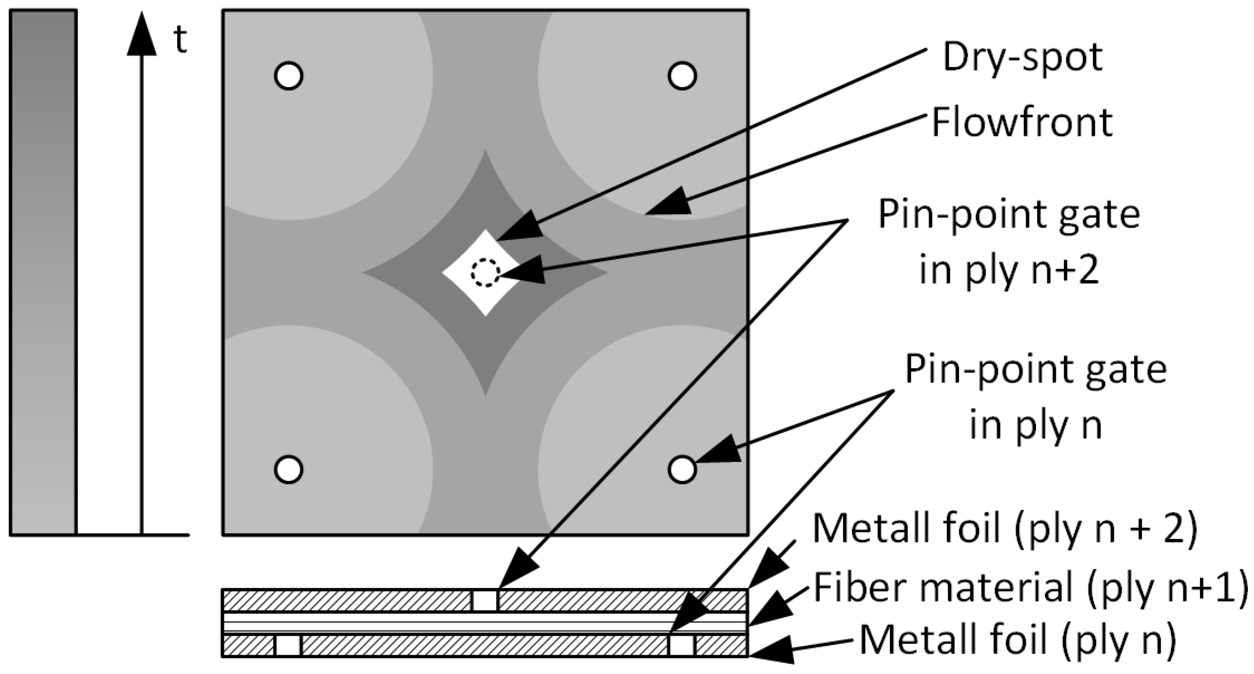
In many studies, the laminate is impregnated in the thickness direction. The metal foils represent a barrier to the resin flow and must therefore be perforated. Consequently, a system of pin-point gates forms in each layer of fiber material. Viewed in cross-section, the holes in the metal foils are usually staggered [14,15,16] so that no dry-spots can form when the flow fronts merge and the trapped gas can escape to the next higher layer (see Figure 1).

Figure 1.
Simplified representation of the hole distribution and the behavior of the flow front during infusion. The different shades of gray represent the flow front progression at different time points t. The darker the gray value, the further the time has progressed.
In [16,18], process parameters that influence the infusion times of FMLs are investigated. The results show that holes in the metal foils significantly reduce the infusion time. If holes in the metal foils are omitted, the infusion time increases with increasing number of metal foils. It is also shown that the holes influence the E-modulus and the strength. However, smaller hole diameters reduce the influence. In order to avoid holes in the metal foils and at the same time to produce the samples in the vacuum infusion process, it remains only to impregnate the fiber material in the plane. Hence, investigating the maximum achievable flow path is a major part of this study. If the flexural rigidity of caul plates is sufficiently high, the infusion time can be significantly reduced [19]. The metal foils between the individual fiber layers can be regarded as caul plates. Therefore, these caul plates are taken into account in the in-plane infusion tests.
All published experiments use a pattern where the holes are arranged with an offset to each other. When flow fronts merge, there is always a risk of air being trapped. If a confluence cannot be prevented, ventilation is usually provided at these points [20]. However, there are also studies that show that a confluence of flow fronts does not lead to voids or dry-spots under certain conditions. According to Bertling et al. [21,22], the parameters that favor the dissolution of dry-spots are diffusion, pressure gradient, viscosity, and permeability. The higher the pressure gradient and permeability, the faster dry-spots will dissolve. The viscosity should be as low as possible and the resin system well degassed. For this work, this results in the two research questions RQ1 and RQ2:
- RQ1
- Which hole configuration (alternating or aligned) allows infiltration of FMLs with large wall thicknesses?
- RQ2
- Do pores and dry-spots occur when the holes are aligned?
2. Materials and Methods
2.1. Experimental Setup
The study of the infusion of thick-walled FMLs can be divided into three main areas:
- In-plane infusion tests
- Out-of-plane infusion tests
- Investigation of temperature distribution
The in-plane infusion tests are used to check the maximum possible flow path and to investigate the influence of a caul plate on the infusion behavior. One advantage of this filling strategy when applied to FMLs is that no holes need to be made in the metal foils. In the out-of-plane infusion tests, different gating strategies and the hole arrangement are investigated. The tests are intended to show which hole arrangement can be used to infiltrate the larger wall thicknesses. In addition to the infusion tests, the temperature distribution over the laminate cross-section is also checked since the viscosity of the resin during infusion depends on the temperature and affects the curing of the epoxy resin.
2.1.1. In-Plane Infusion Tests
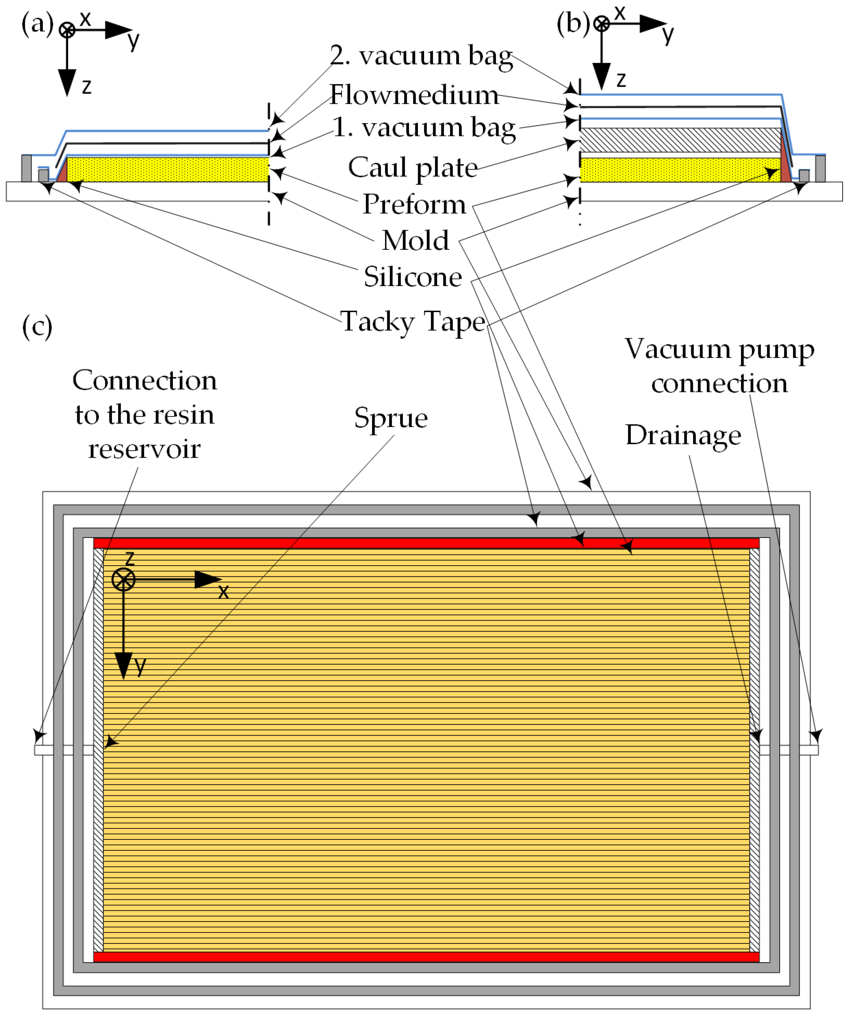
The schematic of the test setup is shown in Figure 2. For the in-plane tests, three tests are performed with a caul plate and three tests without a caul plate. This procedure is used to identify an influence of the metal foils on the flow behavior. However, since a metal foil does not allow visual control of the flow behavior, a 2 mm thick acrylic glass plate (PMMA) is used as the caul plate.
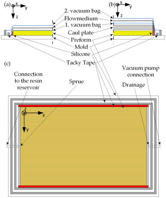
Figure 2.
Schematic illustration of the experimental setup for the in-plane infusion experiments. (a) shows the setup for the experiments without caul plate and (b) the setup for the experiments with caul plate. (c) Top view of the experimental setup.
In order to be able to draw conclusions about the infusion behavior with spring steel foils after the infusion tests, the flexural rigidity (panel stiffness) of the caul plate should be as comparable as possible. If a steel foil (spring steel 0.42 mm thick) is replaced by acrylic glass, the acrylic glass plate would have to be approx. 1.63 mm thick (cf. Table 1). Due to material availability, however, an acrylic glass plate with a thickness of 2 mm had to be used, which means that the flexural rigidity is about twice as high.

Table 1.
Flexural rigidity for PMMA and spring steel.
To prevent the resin from leading at the edges of the specimens, the edges are sealed with liquid silicone before vacuum buildup.
A line sprue is applied to the narrow edge of the laminate to supply the laminate with resin and a drainage line is placed opposite. The test set-up is connected to the resin supply via hoses and to the vacuum pump on the other side.
The layup for the in-plane tests consists of a single layer of unidirectional material (U-E-1182 g/m2, Saertex, Saerbeck, Germany) and the fibers are oriented in the flow direction (x-direction). The specimen size is 500 mm × 800 mm. A container with resin is positioned 400 mm below the test setup and connected via the corresponding hose.
2.1.2. Out-of-Plane Infusion
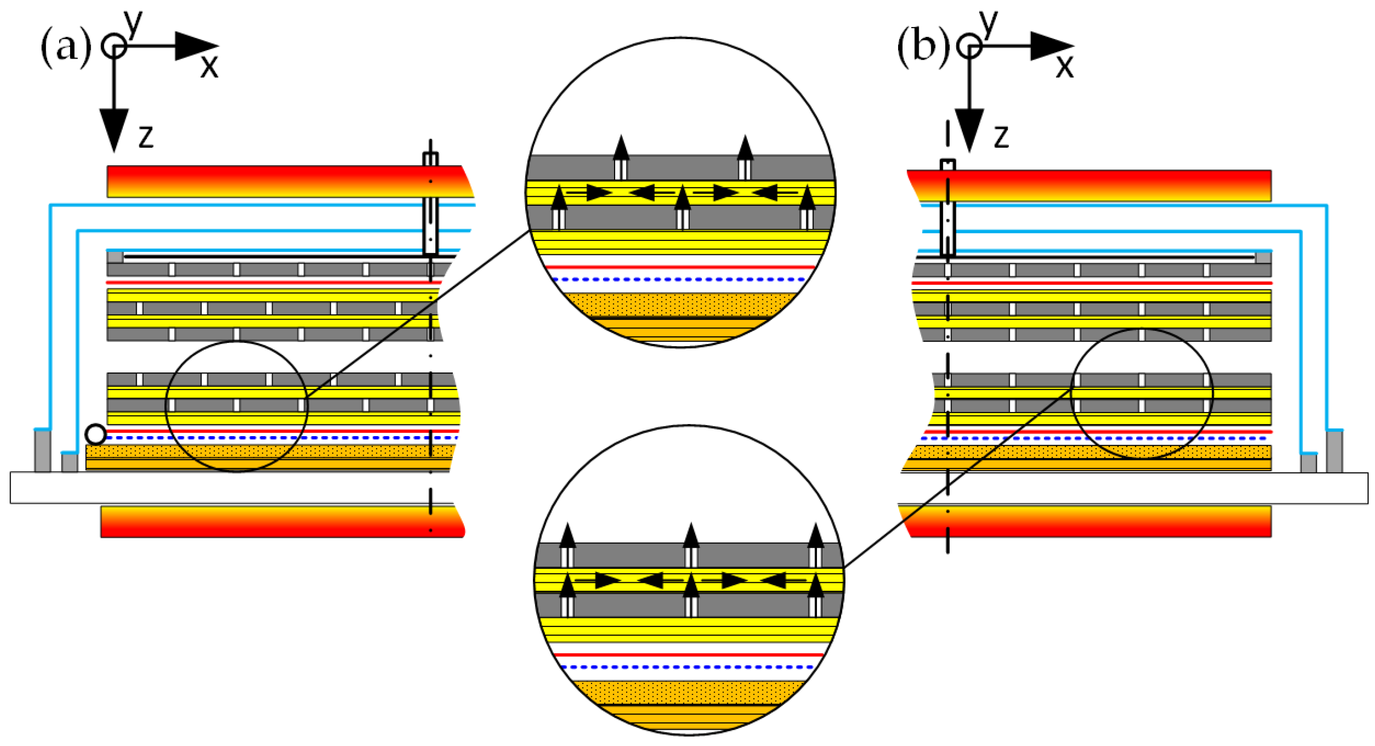
Figure 3 shows the laminate structure in cross-section for out-of-plane infusion. In Figure 3a, the holes in the plates are offset and in Figure 3b, the holes are aligned with each other. In addition to the laminate structure, the resin flow for the two variants is also indicated with arrows. The resin flows through the holes and this results in many individual pin-point gates for the individual plies. If the holes are staggered, the idea is that the residual air can escape through the hole to the next higher ply (Figure 3a). In the other variant (Figure 3b), the pressure gradient should ensure that the residual air or the formation of voids is prevented.
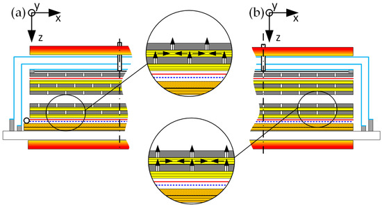
Figure 3.
Laminate structure in cross-section for out-of-plane infusion. Figure part (a) shows the setup for alternating holes and (b) shows the setup for aligned holes.
The laminate structure is identical for all samples. 16 glass fiber UD plies and 15 metal foils are alternately layered. Glass fiber material forms the bottom and top ply.
Figure 4 shows the schematic experimental set-up for the out-of-plane infusion experiments. In the tests with alternating holes, three different test set-ups are investigated to achieve the goal of complete impregnation of the laminate. For test OOP-ALT-003, a ring gate (PE-spiral tube ID 9 mm, Time Out Composites, Bornheim-Sechten, Germany) is used around the laminate. For test OOP-ALT-004, a line sprue is applied. In both trials, two layers of flow medium are positioned underneath the laminate. A perforated release film (Nowoflon ET-6235Z, Nowofol, Siegsdorf, Germany) is used for easy separation between the component and the flow medium (Flonet 112 g/m2, Pultex, Simmerath, Germany). The peel ply (Stitch Ply A, Airtech, Differdange, Luxembourg) protects the laminate and sets a defined surface roughness on both sides. The drainage is formed from a perforated cover sheet, breather (Airweave N10, Airtech, Differdange, Luxembourg), vacuum bag (WL600V, Airtech, Differdange, Luxembourg), and tacky tape (GS-213-31/2, Airtech, Differdange, Luxembourg). For this purpose, tacky tape is stuck along the edges of the perforated cover sheet and the area between the tacky tape is filled with breather (outer drainage). In the middle area of the perforated caul plate, additional tacky tape is stuck in a rectangle to create an inner drainage. This area is also filled with breather. A vacuum line is provided for both the inner and outer drainage, which are connected to the vacuum pump. A vacuum bag seals the drainage together with the tacky tape and thus prevents the resin from penetrating into the drainage from the side. The use of an outer and inner drainage prevents the resin from spreading too quickly in the breather and the laminate from being additionally impregnated from the top side.
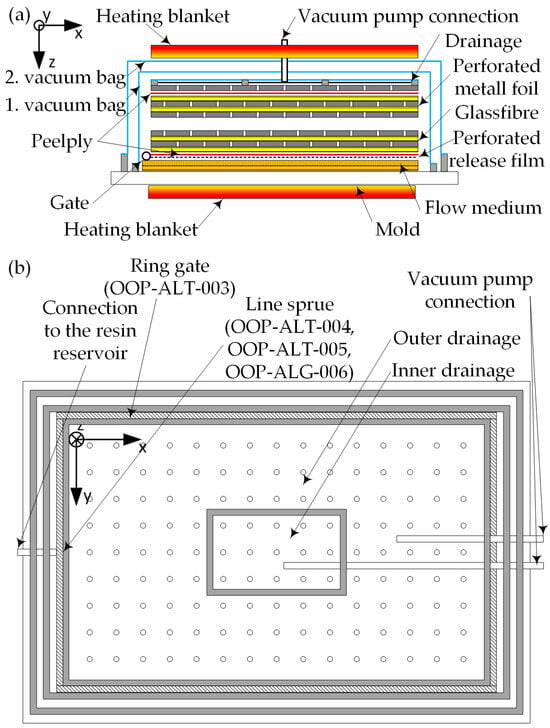
Figure 4.
Schematic illustration of the experimental setup for the out-of-plane infusion experiments. (a) shows the experimental setup in cross section and (b) shows the experimental setup in the top view.
In experiment OOP-ALT-005, one layer of flow medium is placed underneath the laminate and one layer of flow medium is placed on top of the laminate. The drainage is on the opposite side of the line sprue in this test. All experimental set-ups are heated with heating blankets from the bottom (under the plate mold) and top.
For experiment OOP-ALG-006, the setup is equal to the experiment OOP-ALT-004, but the holes in the metal foils are aligned. Table 2 summarizes the experimental setups for the out-of-plane infusion trials.
Table 2.
Different experimental setups.
2.1.3. Temperature Distribution
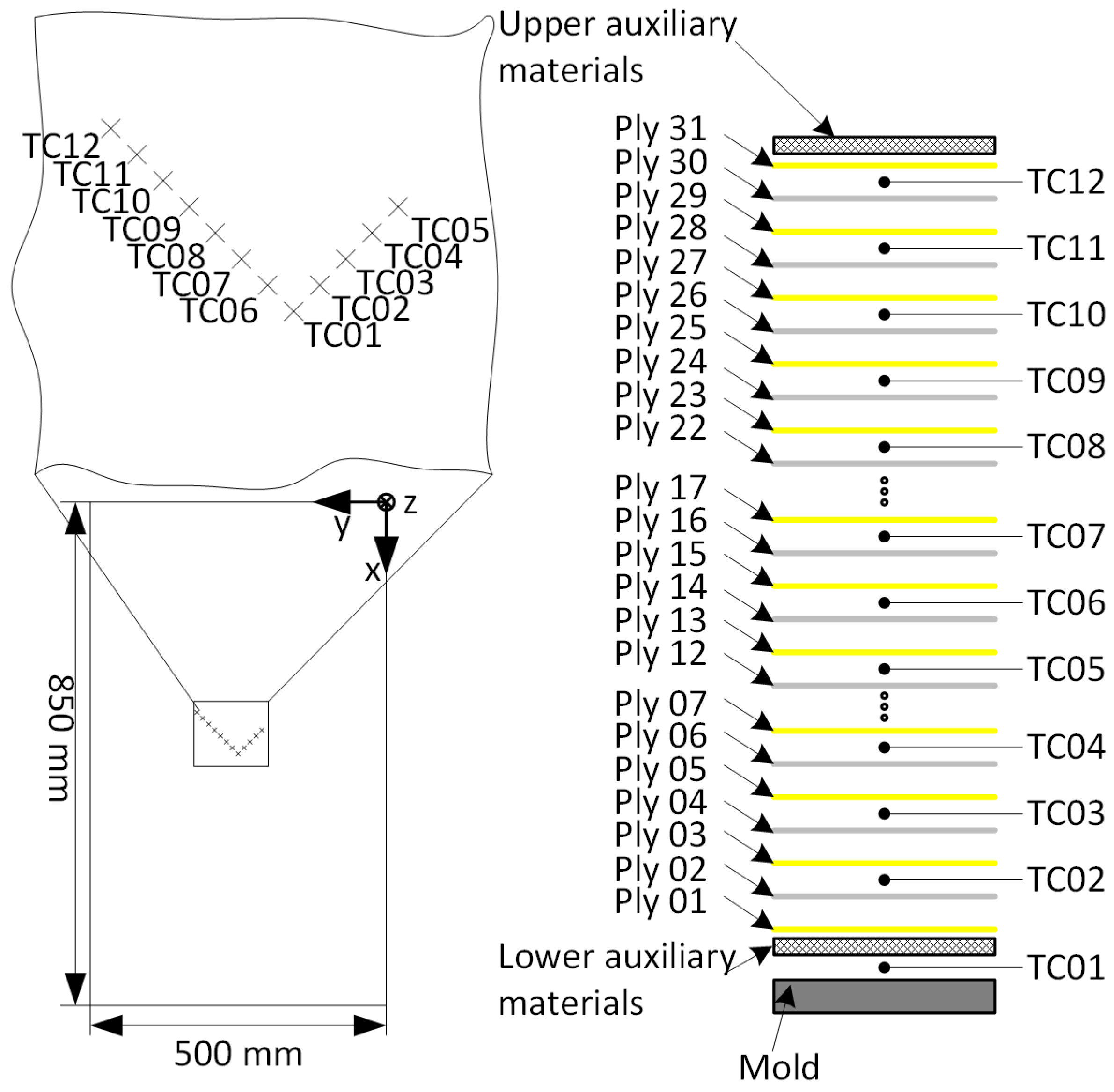
The temperature distribution within the laminate is determined with twelve thermocouples (Autocouple 24, Airtech, Differdange, Luxembourg). The thermocouples are positioned between the individual layers as shown in Figure 5 and Table 3. To prevent the thermocouples from influencing each other, all thermocouples are arranged in a staggered manner but are located in the middle area of the specimen. For the test, the complete layered structure and the various auxiliary materials (flow medium, peel ply, perforated release film, breather) are placed on a plate tool. The plate tool consists of an 8 mm thick steel plate, which is heated from the underside with a heating blanket (LCS Isotherm, Frankfurt a.M, Germany). Two different test setups are investigated. In the first experiment, the test setup is heated only from the underside and covered on the upper side with insulation mats (bubble wrap with aluminum coating). In the second experiment, insulation is replaced by a second heating blanket and the test setup is thus heated from both sides (Cf. Figure 3). The thermocouples are fed out through the tacky tape and connected to a temperature data logger (Extech TM500, FLIR Systems, Nashua, NH, USA). Finally, the entire layer assembly is sealed with a vacuum bag and evacuated before the heating test. Since the later samples for the mechanical tests contain steel foils (Table 4), in contrast to the infusion tests, the steel foils are also used for measuring the temperature distribution. Thus, differences due to the different thermal conductivities are excluded.
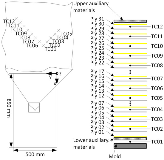
Figure 5.
Schematic illustration of the experimental setup for the temperature distribution experiments. Lower auxiliary materials: two-time flow medium, perforated release film, and peel ply. Upper auxiliary materials: peel ply, caul plate (steel 0.4 mm), and breather.
Table 3.
Position of the thermocouples (TC).
Table 4.
Perforated steel foils.
2.2. Materials Used
For the investigations, the fiber material Saertex U-E-1182 g/m2 (Table 5) is used [23]. The material was selected for the tests because it is a standard material in the wind power industry. In addition, a UD material allows the metal foil to be relieved due to its higher stiffness compared to another semi-finished fiber product.
Table 5.
Fiber material Saertex U-E-1182 g/m2-1270 mm [23].
The resin Epikote MGS RIMR035c (Westlake Corporation, Houston, TX, USA) used is an epoxy resin that is prone to the wind energy brand. As Curing Agent Epikure MGS RIMH037 (Westlake Corporation, Houston, TX, USA) is applied. Thanks to the low viscosity (see Table 6) and the possibility of curing the resin system at room temperature, laminates can be produced easily using vacuum infusion.
Table 6.
Resin Epikote Resin MGS RIMR035c and Epikure Curing Agent MGS RIMH037 [24].
For the determination of the temperature distribution, steel foils are used in the laminate because the later specimens for mechanical testing are produced with these foils. The metal foils absorb a large part of the bearing strength in an FML and the fiber material is intended to relieve the metal. The higher the stiffness of the fiber material, the greater this effect. The spring steel also has a high stiffness and therefore the combination of materials provides excellent bearing strength.
The steel foils are subjected to surface pretreatment for good adhesion and therefore do not match the procedure chosen for the infusion tests (see Section 2.3).
In the infusion experiments, the metal foils are made of aluminum (see Table 7). In contrast to steel foils, aluminum foils are easier to process mechanically. This makes it easier to drill the holes and cut the foils to size. For the impregnation tests, the hole geometry (spacing and diameter) is more important than the metal foil material. The aluminum foils therefore represent a good compromise between cost and benefit.
Table 7.
Perforated aluminum foils.
2.3. Procedure
2.3.1. Infusiontests
For the in-plane and out-of-plane infusion experiments the experimental procedure is similar. The set-up is heated to the infusion temperature (see Table 8). A vacuum test is performed with a rotameter (FR2000, Key Instruments, Croydon, USA). The rotameter is integrated into the drainage line outside the cavity for this purpose. If the flow is zero, the vacuum setup is considered to be sufficiently sealed. Before infusion, the required amount of resin is mixed and degassed at a pressure of 1 mbar. The resin container is positioned approx. 400 mm below the plate mold and the resin line is fixed to the container. Shortly before the infusion starts, the upper heating blanket is removed. After opening the resin line, the resin flows into the cavity and impregnates the fiber material. The test ends after 120 min at the latest, as the pot life of the resin has been reached. All lines (resin and drainage lines) are closed and the laminate is cured for 5 h at 60 °C.
Table 8.
Differences in the parameters in the in-plane and out-of-plane infusion tests.
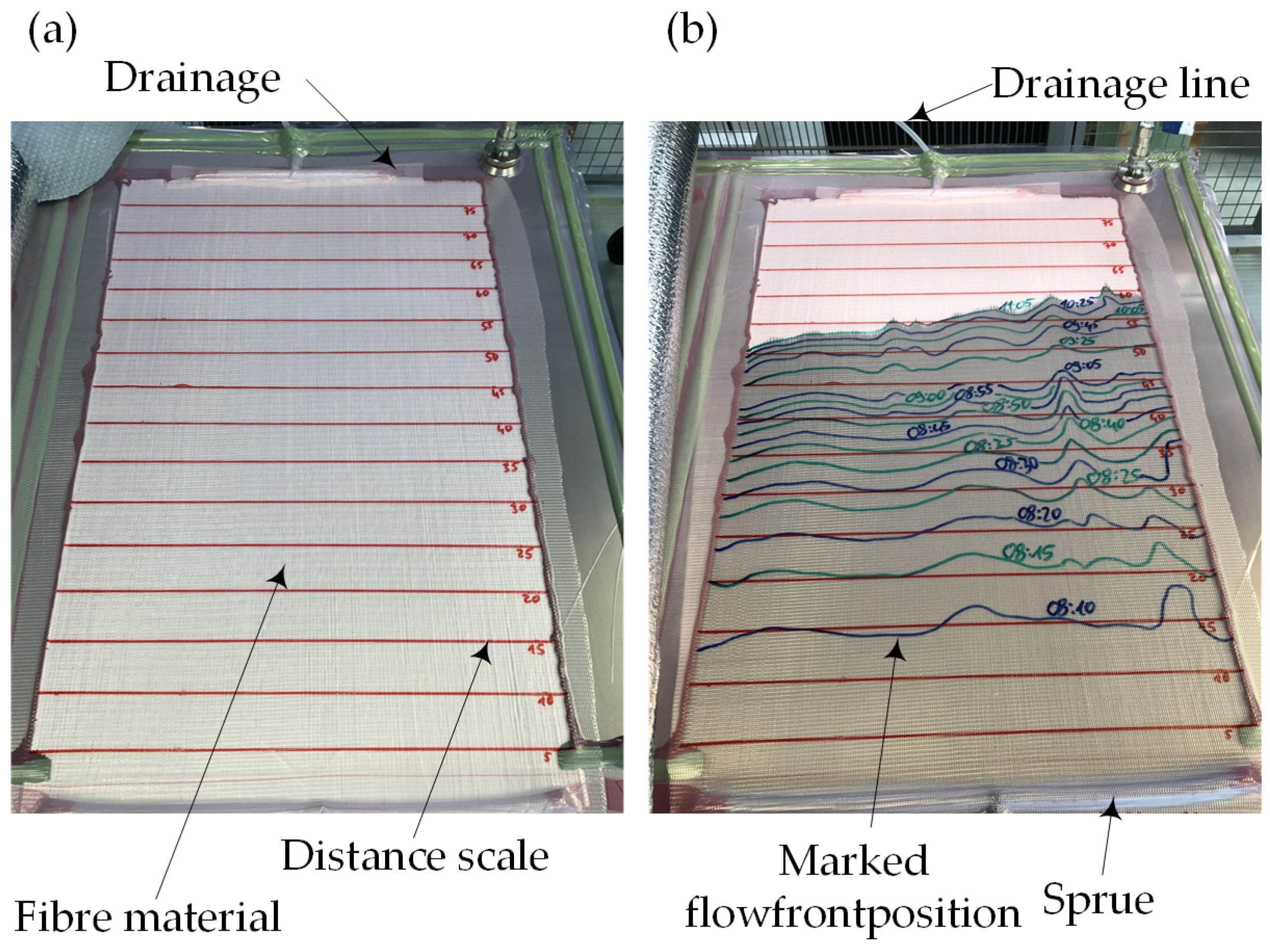
During the in-plane infusion experiments, the flow front progress is documented every 5 min with a felt-tip pen on the vacuum bag. The flow front progress is documented by means of a picture at the end of the test. Figure 6a shows the experimental set-up before infusion and in Figure 6b the progress of the flowfront is marked with lines in green and blue colors.
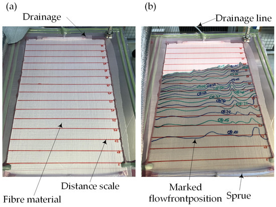
Figure 6.
(a) Experimental set-up for in-plane infusion. (b) Progress of the flowfront.The red lines mark the distance to the sprue line and have a distance of 50 mm.
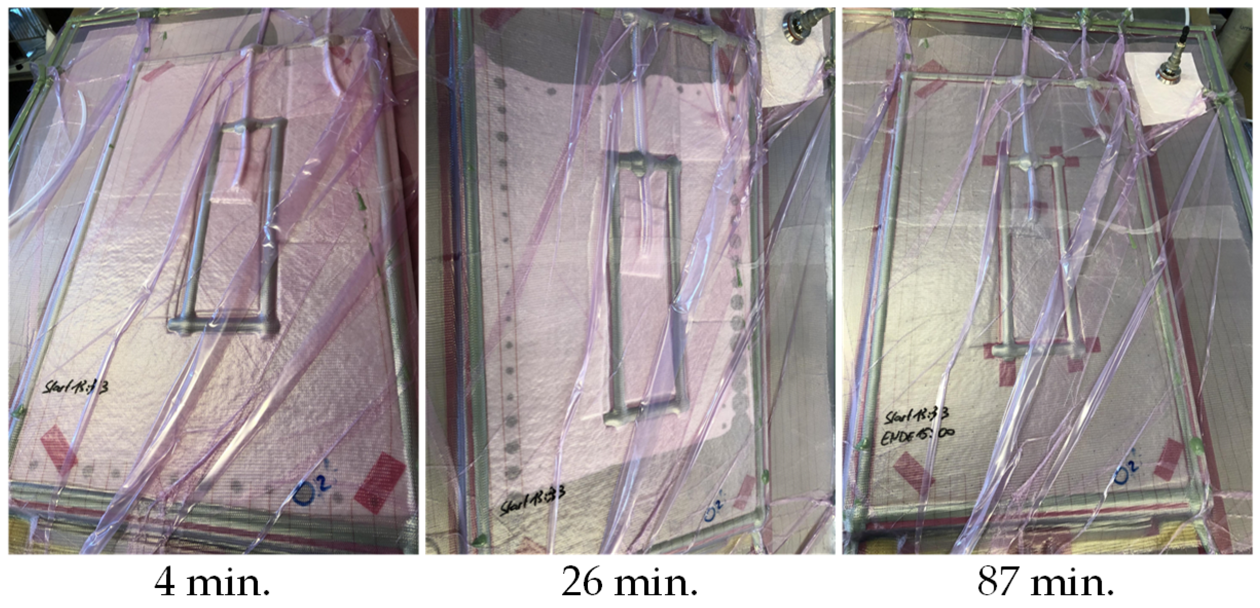
In Figure 7, the progress of the infusion for the out-of-plane infusion tests is shown. The resin enters the drainage via the holes in the metal foils and forms a closed flow front with increasing time.
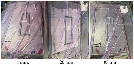
Figure 7.
Progress of the infusion at different times. The entry of the resin into the drainage can be seen through the holes in the edge area of the sample (4 min and 26 min). After 87 min, the sample (OOP-ALG-006) is completely impregnated.
The metal foils in the out-of-plane infusion experiments are treated with release agent (Zyvax Departure, Chem-Trend, Maisach Gernlinden, Germany) on both sides before the start of the experiment. A total of three layers of release agent are applied. This makes it possible to disassemble the laminate structure layer by layer after curing. The individual glass fiber layers are then visually inspected and dry-spots and voids can be identified. The ultrasonic method was available as a NDT method, but this method could not be used for the inspection due to the component thickness and the large number of metal foils. Voids and dry-spots in a fiberglass laminate can be easily identified in back light. Figure 8a shows the experimental set-up for the out-of-plane infusion tests. Figure 8b–d show examples of three different plies of a laminate after demolding. The dry spots are clearly visible in layer n and n + 2, whereas no dry-spot is visible in layer n − 2.
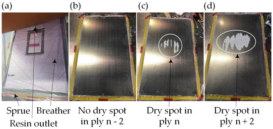
Figure 8.
(a) Experimental set-up for out-of-plane infusion. (b) No dry-spots visible in ply n − 2. (c) Dry-spot in ply n. (d) Dry-spot in ply n + 2.
2.3.2. Temperature Distribution
To determine the temperature distribution, the experimental setup is evacuated to a pressure of approx. 200 mbar and heated on the plate mold. In the first test variant, only the lower heating blanket is used for heating and the upper side is insulated. In the second variant, the heating blanket on the upper side is also used for heating. In both tests, the temperature controller is set to 50 °C and no heating ramp is specified. Thermocouple TC01 measures the temperature of the plate mold and thermocouple TC012 measures the temperature on the top side of the laminate (see Figure 5). For all thermocouples, a temperature value is recorded every minute. Figure 9a shows the test setup with the thermocouples taken out and Figure 9b the fixation of a thermocouple in the laminate.
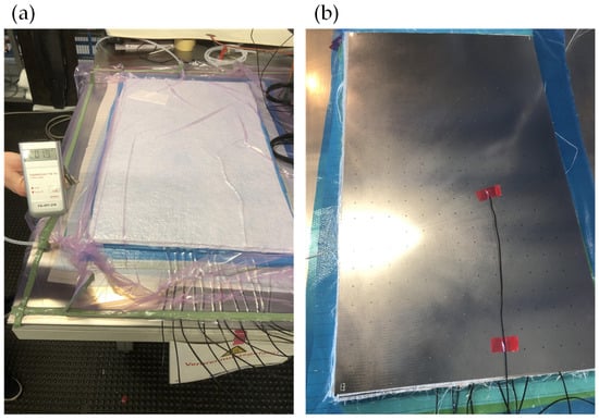
Figure 9.
(a) Experimental set-up for the temperature distribution test. (b) Fixation of a thermocouple in the laminate.
3. Results
3.1. In Plane Infusion
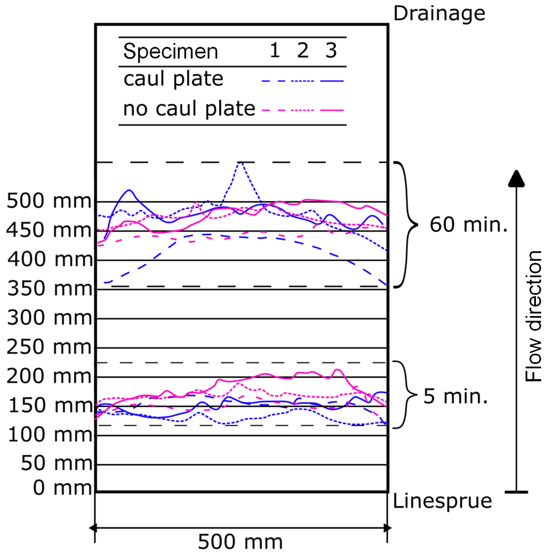
Figure 10 shows the results of the in-plane infusion experiments. For a better overview, the flow fronts are shown only after 5 min and after 60 min. A clear difference between the specimens with caul plate and without caul plate is not evident. Furthermore, even after 60 min infusion time, no flow path longer than 500 mm is observed. The results also show that no race-tracking occurred at the plate edges.
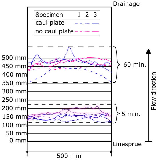
Figure 10.
Results of the in-plane infusion trials. The resulting flow fronts after 5 and 60 min for the tests with caul plate (blue) and without caul plate (magenta) are shown. Three tests have been carried out per test series.
3.2. Out of Plane Infusion
In Table 9, the results of the out-of-plane infusion trials with alternating holes are summarized. In none of the tests could all glass fiber plies (16 plies) be impregnated without dry-spots. A maximum of 14 layers are possible when using flow medium on both sides of the laminate. Unlike in the other tests, the dry-spots do not occur in the upper plies but occur in plies 15 and 17 in the rear third of the plate (see Figure A3 in Appendix A). In both scenarios, the one with a ring gate and the one with a linear gate, about two-thirds of the glass fiber layers were completely impregnated with the matrix (see Figure A1 and Figure A2).
Table 9.
Results of the out-of-plane infusion trials with alternating holes.
The result of the test with aligned holes is shown in Figure A4. All 16 glass fiber plies are completely impregnated.
3.3. Temperature Distribution
The results of temperature distribution with heating on one side and on both sides are shown in Figure 11. With one-sided heating, the target temperature of 50 °C is not reached after 120 min despite thermal insulation. With heating on both sides, the target temperature is reached after approx. 120 min and the temperature is distributed more homogeneously. In contrast to the other thermocouples, the TC01 thermocouple has not delivered uniform measured values. During the test with heating on both sides, thermocouple TC07 failed.
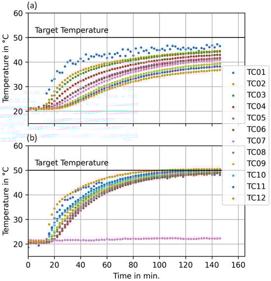
Figure 11.
Results of the temperature distribution measurement. (a) Heating from below. (b) Heating on both sides.
3.4. Discussion
3.4.1. In-Plane Infusion
There is no clear difference in the infusion between the samples with and without a caul plate. The caul plate does not appear to have a major influence on infiltration. However, Chen et al. [19] found that a caul plate does have an influence on the flow velocity. In the investigations, caul plates made of different materials and with different thicknesses were used. The studies mainly focused on the thickness variation that can be reduced by caul plates. But, in a series of tests, the infusion times were also compared. Infusion tests were carried out with and without caul plates. In this series of tests, the caul plate consisted of a 5 mm thick acrylic glass plate and led to shorter infusion times.
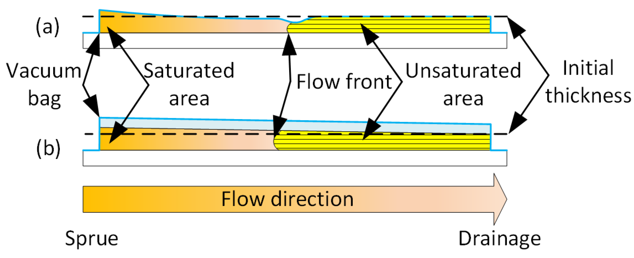
The reason for the difference lies in the compaction of the fiber material during infusion (see Figure 12). Without a caul plate, the fiber material is compressed more at the flow front (transition between the saturated and unsaturated area), thus reducing the permeability. During infusion, the pressure within the cavity initially increases in the sprue area. As the pressure difference between the pressure in the cavity and the ambient pressure thus decreases, the cavity height in this area increases [25]. If a caul plate is used which has a high flexural rigidity, the cavity height is increased over the entire cross-section (in the flow direction of the resin). This reduces the compaction of the fiber material and increases the permeability [26,27].
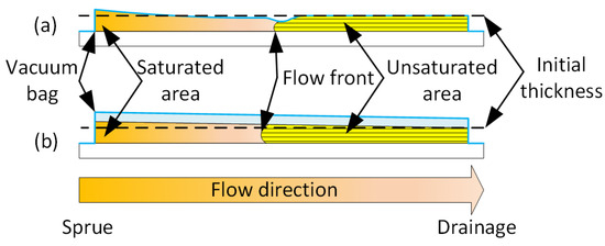
Figure 12.
Schematic representation of the change in thickness during infusion. (a) Without caul plate. (b) With caul plate. Based on Chen et al. [19].
Presumably the rigidity of the caul plate used in this work is not high enough to increase the flow rate. Since the flexural rigidity of the acrylic glass plate is about twice as high as that of the steel metal foils, in-plane infusion is not expedient for the envisaged sample size (800 mm × 500 mm × 20 mm).
3.4.2. Out-of-Plane Infusion
The results of the out-of-plane infusion tests show that all glass fiber layers could only be impregnated in the scenario with all holes aligned.
Hole spacing is thus obviously suitable so that no dry-spots and no voids are created when the flow fronts flow together. According to Bertling et al. [21,22], this effect is favored by the following parameters:
- Diffusion⇒ resin is degassed properly
- Pressure gradient⇒ as large as possible
- Viscosity⇒ as low as possible
- Permeability⇒ as large as possible
During diffusion, the gas diffuses into the resin. A prerequisite here is that the resin can absorb gas. Therefore, the resin must be degassed as well as possible before infusion, and the gas already dissolved in the resin due to storage and mixing must be removed.
It follows from Bertling et al. that a sufficiently large pressure gradient, which among other parameters depends on the distance between the gate and the point of confluence, compresses the enclosed gas volume. During the infusion of the FML, the holes each form pin-point gates and the resin spreads radially from the pin-point gate. The farther the flow front is from the gate, the smaller the pressure gradient becomes. It can be concluded from this that if the holes are too far apart, dry-spots and voids will form.
Bertling et al. have also investigated the dissolution behavior of dry-spots and pores as a function of fluid viscosity. The results show that a lower viscosity leads to faster dissolution. For permeability, the investigations show that dissolution behavior is accelerated at a higher permeability.
The tests on the alternating holes show that a maximum of 14 out of 16 layers can be impregnated and no dry-spots or voids are recognizable. Similar laminates have been examined in the literature and show that the procedure works for thinner laminates. Dariushi et al. show a comparison of infusion times and an increase in infusion time is observed for thicker laminates [18].
3.4.3. Temperature Distribution
The results of the heat distribution measurement show that it makes sense to heat the laminate from the top and bottom for quick and even heating. In addition to the use of heating blankets, heating in an oven or autoclave would be another way to ensure this. However, the tests have shown that heating only from the mold side has a positive effect on the infusion. This means that the temperature on the upper side of the laminate is cooler, which increases the viscosity of the epoxy resin. This slows down the spread of the resin in the drainage and the holes are washed over more slowly by the resin. The resin therefore has more time to flow through the laminate in the thickness direction and to transport gas out of the laminate. If the resin were distributed more quickly via the drainage and the breather, the fiber material would also be impregnated from the top. The result would then be similar to the experiment with the flow medium, which is located on the top side of the laminate (OOP-ALT-005). When infusing in an oven or autoclave, it is more difficult to utilize the effect.
The temperature distribution is not only important for the infusion but also for the curing of the laminate. If the temperature is unevenly distributed across the laminate, there will also be differences in the curing of the laminate. This can result in incomplete consolidation and differences in fiber volume content [28,29]. The ability to remove a heating blanket and replace it as required therefore allows the infusion to be controlled and a uniform curing of the laminate to be achieved.
4. Conclusions
In this work, tests were carried out on the impregnation of thick-walled fiber metal laminates. Infusion in the plane was ruled out for this sample size, as the maximum flow paths are too short. When infusing in the thickness direction, it has been found that the alignment of the holes in the metal foils plays a major role. If the holes are aligned, greater laminate thicknesses are possible without pores or dry-spots.
The advantage of heating both sides of the laminate with heating blankets is that the laminate can be heated more quickly and evenly. However, it is advantageous for the infusion if the upper heating blanket is removed.
The research question of which hole configuration can be used to infiltrate the larger laminate thicknesses (RQ1) has been answered with this work. Infusion is significantly faster with aligned holes than with staggered holes. The subsequent research question RQ2, whether pores or dry-spots also occur with aligned holes, can be answered in the negative. The visual inspection of the laminates did not reveal any voids or dry-spots.
In fact, further investigations into optimized hole spacing and hole diameters are necessary and flow simulation is also suitable for this purpose. Initial investigations into the mechanical properties (static and dynamic tests) have been carried out and the results are promising. With the findings on the infusion of thick-walled FMLs, 14 test panels measuring 500 mm × 800 mm × 20 mm were successfully manufactured.
In contrast to the procedures found in the literature, the alignment of the holes in the metal foils leads to shorter infusion times. This means that larger laminate dimensions than those investigated in the literature are also possible, which is supported by the investigations presented.
Blade connections of rotor blades for wind turbines are possible practical applications, at least from a manufacturing perspective. Further considerations are required for a more precise design and the transition from metal to fiber composite materials. A similar issue arises in the connection of wings to an aircraft fuselage. Finally, the vacuum infusion of wing shells is also being investigated or is already being used in the aviation industry.
Author Contributions
Conceptualization, A.H., C.B., and L.B.; Investigation, A.H., C.B., and L.B.; Methodology, A.H.; Project administration, L.B.; Validation, C.B.; Writing—original draft, A.H. All authors have read and agreed to the published version of the manuscript.
Funding
This research was funded by Federal Ministry for Economic Affairs and Climate Action grant number 03EE3083A.
Institutional Review Board Statement
Not applicable.
Informed Consent Statement
Not applicable.
Data Availability Statement
The data of the experiments can be requested from the authors.
Conflicts of Interest
The authors declare no conflicts of interest.
Appendix A
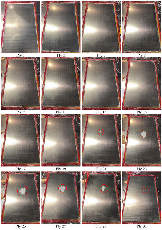
Figure A1.
Images of the demolded glass-fiber plies of the test OOP-ALT-003. The red circles indicate the dry-spots in the single plies. The metal layers are not shown.
Figure A1.
Images of the demolded glass-fiber plies of the test OOP-ALT-003. The red circles indicate the dry-spots in the single plies. The metal layers are not shown.
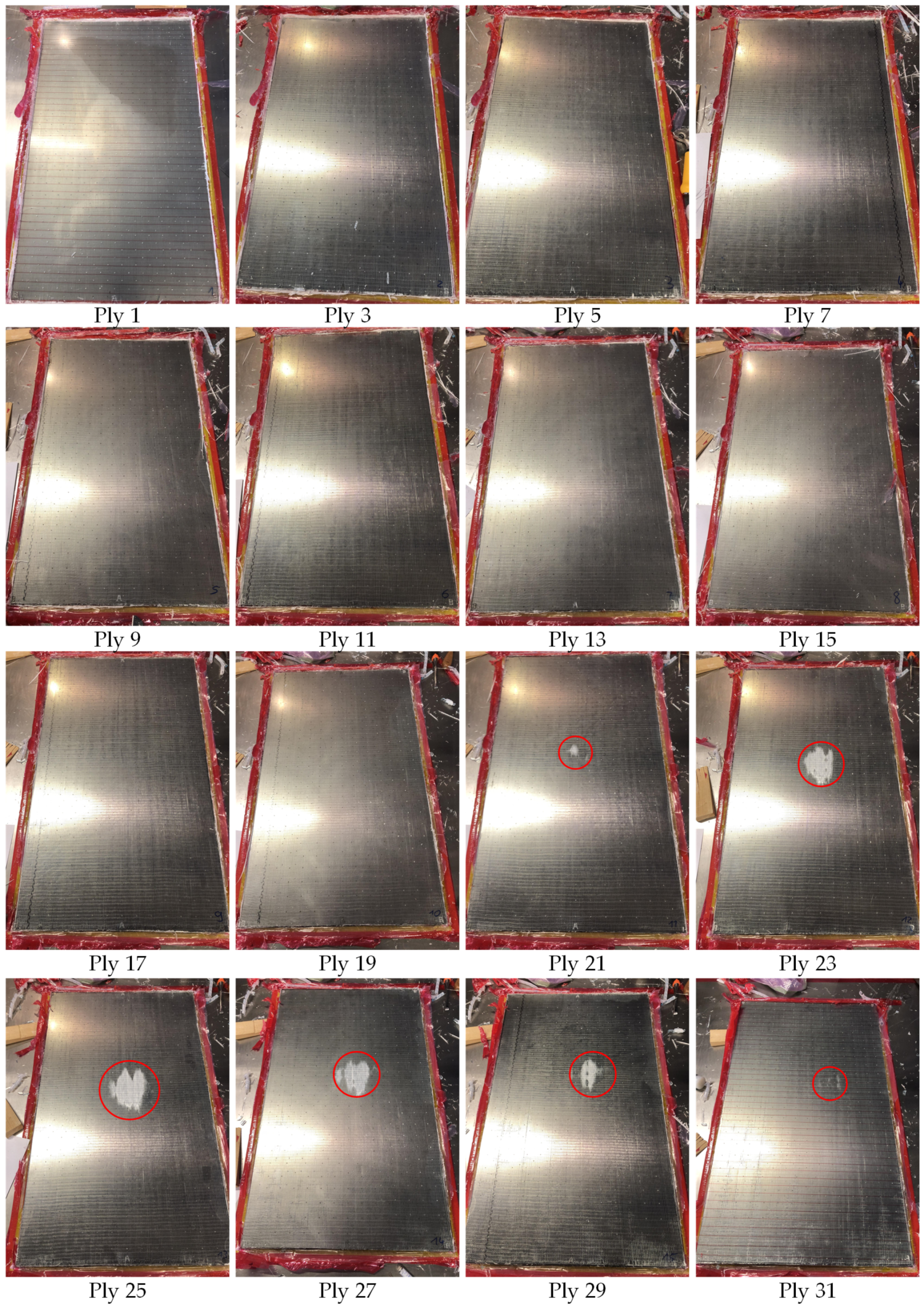

Figure A2.
Images of the demolded glass-fiber plies of the test OOP-ALT-004. The red circles indicate the dry-spots in the single plies. The metal layers are not shown.
Figure A2.
Images of the demolded glass-fiber plies of the test OOP-ALT-004. The red circles indicate the dry-spots in the single plies. The metal layers are not shown.
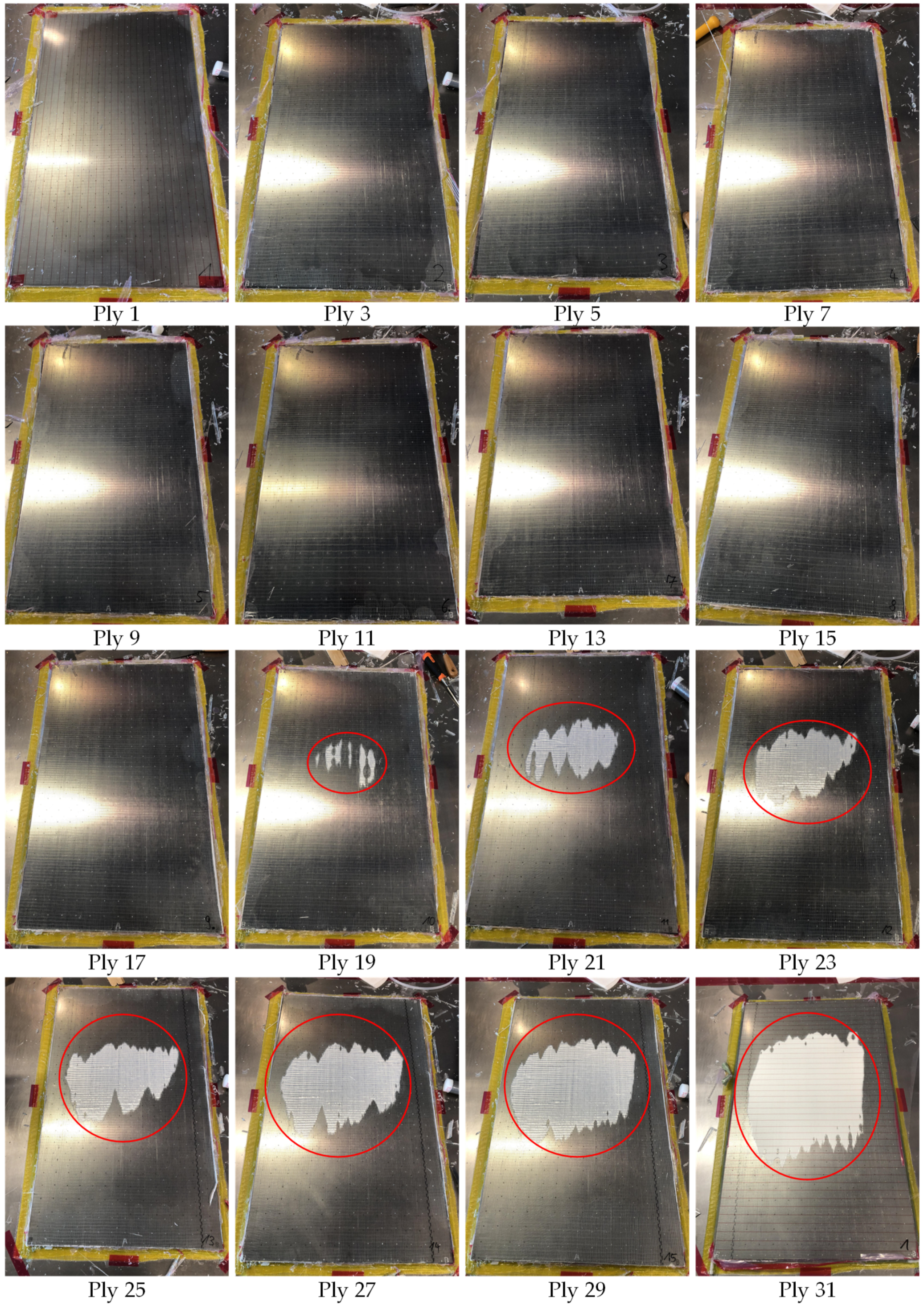
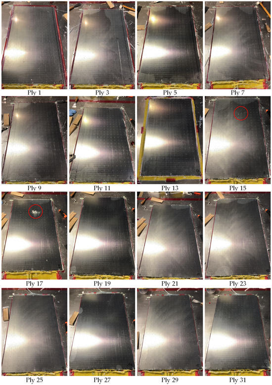
Figure A3.
Images of the demolded glass fiber plies of the test OOP-ALT-005. The red circles indicate the dry-spots in the single plies. The metal layers are not shown.
Figure A3.
Images of the demolded glass fiber plies of the test OOP-ALT-005. The red circles indicate the dry-spots in the single plies. The metal layers are not shown.
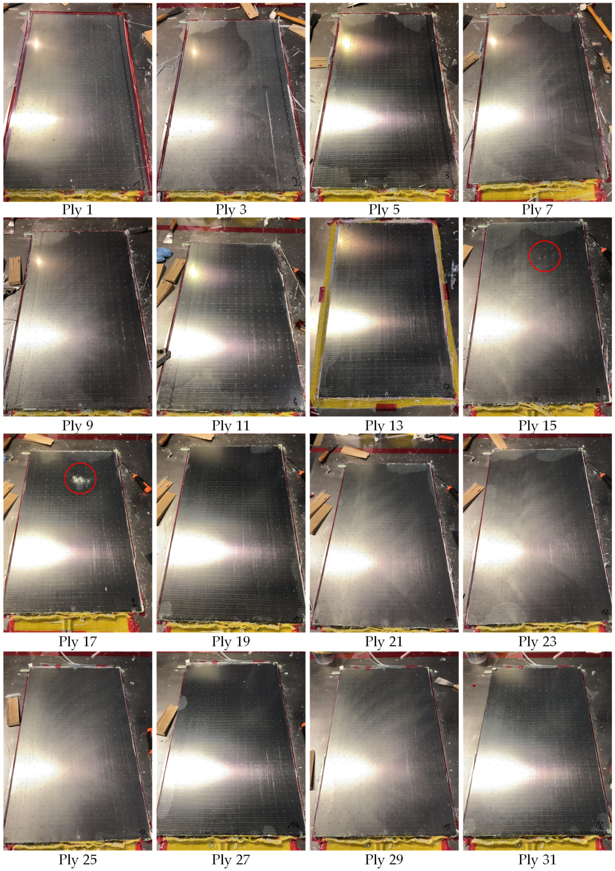
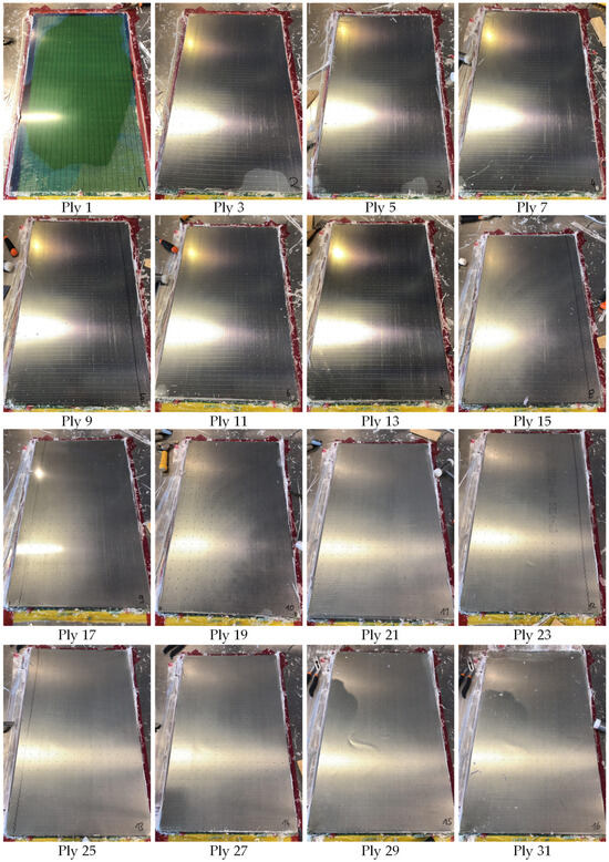
Figure A4.
Images of the demolded glass fiber plies of the test OOP-ALG-006. The metal layers are not shown.
Figure A4.
Images of the demolded glass fiber plies of the test OOP-ALG-006. The metal layers are not shown.

References
- Asundi, A.; Choi, A.Y. Fiber metal laminates: An advanced material for future aircraft. J. Mater. Process. Technol. 1997, 63, 384–394. [Google Scholar] [CrossRef]
- Ding, Z.; Wang, H.; Luo, J.; Li, N. A review on forming technologies of fibre metal laminates. Int. J. Lightweight Mater. Manuf. 2021, 4, 110–126. [Google Scholar] [CrossRef]
- Czerwinski, F. Current Trends in Automotive Lightweighting Strategies and Materials. Materials 2021, 14, 6631. [Google Scholar] [CrossRef] [PubMed]
- Sinmazçelik, T.; Avcu, E.; Özgür Bora, M.; Çoban, O. A review: Fibre metal laminates, background, bonding types and applied test methods. Mater. Des. 2011, 32, 3671–3685. [Google Scholar] [CrossRef]
- Boose, Y.; Kappel, E.; Stefaniak, D.; Prussak, R.; Pototzky, A.; Weiß, L. Phenomenological investigation on crash characteristics of thin layered CFRP-steel laminates. Int. J. Crashworthiness 2020, 27, 289–298. [Google Scholar] [CrossRef]
- Wanhill, R.J.H. GLARE®: A Versatile Fibre Metal Laminate (FML) Concept. In Aerospace Materials and Material Technologies; Prasad, N.E., Wanhill, R.J.H., Eds.; Springer: Singapore, 2017; pp. 291–307. [Google Scholar]
- Stefaniak, D.; Prussak, R. Chances and challenges in the application of fiber metal laminates. Adv. Mater. Lett. 2019, 10, 91–97. [Google Scholar] [CrossRef]
- Vasudevan, A.; Navin Kumar, B.; Victor Depoures, M.; Maridurai, T.; Mohanavel, V. Tensile and flexural behaviour of glass fibre reinforced plastic—Aluminium hybrid laminate manufactured by vacuum resin transfer moulding technique (VARTM). Mater. Today Proc. 2021, 37, 2132–2140. [Google Scholar] [CrossRef]
- Khalid, M.Y.; Arif, Z.U.; Al Rashid, A.; Shahid, M.I.; Ahmed, W.; Tariq, A.F.; Abbas, Z. Interlaminar shear strength (ILSS) characterization of fiber metal laminates (FMLs) manufactured through VARTM process. Forces Mech. 2021, 4, 100038. [Google Scholar] [CrossRef]
- Xiao, H.; Sultan, M.T.H.; Shahar, F.S.; Gaff, M.; Hui, D. Recent developments in the mechanical properties of hybrid fiber metal laminates in the automotive industry: A review. Rev. Adv. Mater. Sci. 2023, 62, 20220328. [Google Scholar] [CrossRef]
- Beyland, L. Stärker am Wind—Ein Neues Verbindungskonzept für Windkraftrotorblätter. Technical Report, Institute of Composite Structures and Adaptive Systems. Seite 44–45. 2022. Available online: https://elib.dlr.de/189168/ (accessed on 6 May 2024).
- Petersen, E.; Englisch, N.; Brand, L.M.; Mahrholz, T.; Hühne, C. Potential of fibre metal laminates in root joints of wind energy turbine rotor blades. J. Phys. Conf. Ser. 2022, 2265, 032039. [Google Scholar] [CrossRef]
- Beyland, L. Innovativer Blattanschluss für extrem lange Rotorblätter. Ingenieurspiegel 2019, 2019, 26–28. [Google Scholar]
- Loos, A.; Tuncol, G.; Long, K.; Cano, R.; Jensen, B.; Weiser, E. Flow visualization and modeling of the resin infusion process during manufacture of fiber metal laminates by VARTM. In Proceedings of the 17th International Conference on Composite Materials, Edinburgh, UK, 27–31 July 2009. [Google Scholar]
- Jensen, B.J.; Cano, R.J.; Hales, S.J.; Alexa, J.A.; Weiser, E.S.; Loos, A.; Johnson, W.S. Fiber metal laminates made by the VARTM process. In Proceedings of the 17th International Conference on Composite Materials, Edinburgh, UK, 27–31 July 2009. [Google Scholar]
- Dariushi, S.; Rezadoust, A.M.; Kashizadeh, R. Effect of processing parameters on the fabrication of fiber metal laminates by vacuum infusion process. Polym. Compos. 2019, 40, 4167–4174. [Google Scholar] [CrossRef]
- Kazemi, M.; Shanmugam, L.; Yang, L.; Yang, J. A review on the hybrid titanium composite laminates (HTCLs) with focuses on surface treatments, fabrications, and mechanical properties. Compos. Part A Appl. Sci. Manuf. 2020, 128, 105679. [Google Scholar] [CrossRef]
- Dariushi, S.; Farahmandnia, S.; Rezadoust, A.M. An experimental investigation on infusion time and strength of fiber metal laminates made by vacuum infusion process. Proc. Inst. Mech. Eng. Part L J. Mater. Des. Appl. 2020, 235, 1800–1808. [Google Scholar] [CrossRef]
- Chen, D.; Arakawa, K.; Uchino, M. Effects of the addition of a cover mold on resin flow and the quality of the finished product in vacuum-assisted resin transfer molding. Polym. Compos. 2014, 37, 1435–1442. [Google Scholar] [CrossRef]
- Boccard, A.; Lee, W.I.; Springer, G.S. Model for determining the vent locations and the fill time of resin transfer molds. J. Compos. Mater. 1995, 29, 306–333. [Google Scholar] [CrossRef]
- Bertling, D.; Kaps, R.; Mulugeta, E. Analysis of dry-spot behavior in the pressure field of a liquid composite molding process. CEAS Aeronaut. J. 2016, 7, 577–585. [Google Scholar] [CrossRef]
- Bertling, D.; Jose, S.; Liebers, N. Analysis and simulation of dry-spot behavior in Liquid Composite Molding. In Proceedings of the 14th International Conference on Flow Processes in Composite Materials, Lulea, Sweden, 30 May–1 June 2018. [Google Scholar]
- Saertex. Technical Datasheet U-E-1182 g/m2-1270 mm. 2021. Available online: https://www.saertex.com/download/document/a5d2a2655a2e550cbe82234decd0d54d (accessed on 6 May 2024).
- Westlake Epoxy. Technical Data Sheet Epikote Resin MGS RIMR035c. 2022. Available online: https://shop.swiss-composite.ch/shop/resources/downloads/ZZB101004/t-epikote-rimr-035c-e.pdf (accessed on 6 May 2024).
- Hindersmann, A. Confusion about infusion: An overview of infusion processes. Compos. Part A Appl. Sci. Manuf. 2019, 126, 105583. [Google Scholar] [CrossRef]
- Karaki, M.; Younes, R.; Trochu, F.; Lafon, P. Progress in experimental and theoretical evaluation methods for textile permeability. J. Compos. Sci. 2019, 3, 73. [Google Scholar] [CrossRef]
- Fratta, C.D.; Klunker, F.; Trochu, F.; Ermanni, P. Characterization of textile permeability as a function of fiber volume content with a single unidirectional injection experiment. Compos. Part A Appl. Sci. Manuf. 2015, 77, 238–247. [Google Scholar] [CrossRef]
- Qiao, Y.; Zhang, J.; Zhang, M.; Hu, H.; Liu, L.; Zhai, P.; Li, S. Numerical analysis on the flow–compaction behavior and the effect of interface permeability in thick composite plates during autoclave processing. J. Mater. Sci. 2018, 53, 14412–14422. [Google Scholar] [CrossRef]
- Li, X.; Wang, J.; Li, S.; Ding, A. Cure-induced temperature gradient in laminated composite plate: Numerical simulation and experimental measurement. Compos. Struct. 2020, 253, 112822. [Google Scholar] [CrossRef]


Disclaimer/Publisher’s Note: The statements, opinions and data contained in all publications are solely those of the individual author(s) and contributor(s) and not of MDPI and/or the editor(s). MDPI and/or the editor(s) disclaim responsibility for any injury to people or property resulting from any ideas, methods, instructions or products referred to in the content. |
© 2024 by the authors. Licensee MDPI, Basel, Switzerland. This article is an open access article distributed under the terms and conditions of the Creative Commons Attribution (CC BY) license (https://creativecommons.org/licenses/by/4.0/).