Abstract
The choice of efficient methods for the immobilization of high-level waste (HLW) resulting from the reprocessing of spent nuclear fuel (SNF) is an important scientific and practical task. The current policy of managing HLW within a closed nuclear fuel cycle envisages its vitrification into borosilicate (B-Si) or alumina–phosphate (Al-P) glasses. These wasteforms have rather limited waste loading and can potentially impair their retaining properties on devitrification. The optimal solution for HLW immobilization could be separating radionuclides into groups using dedicated capacious durable matrices. The phases of the Nd2O3–ZrO2–TiO2 system in this respect are promising hosts for the REE (rare earth elements: Nd, Ce, La, Pr, Sm, Gd, Y) –MA (MA: Am, Cm) fraction of HLW. In this manuscript, we present data on the composition of the samples analyzed, their durability in hot water, their behavior under irradiation, and their industrial manufacturing methods.
1. Introduction
Over the past 65 years, the concentration of CO2 in the Earth‘s atmosphere has increased by a quarter–from 315 ppm in 1958 to 420 ppm in 2023—and continues to grow. By March 2024, its level had increased by another 5 ppm, the largest jump in the entire history of observations. A similar concentration of CO2 in the air was reached 3–5 million years ago, when the temperature was higher by 2–3 °C, and the sea level was 10–20 meters higher than today. The increase in the amounts of climate-active gases is caused by the combustion of fossil fuels and transport. A huge contribution to environmental degradation is made by particulate matter, up to 2.5 μm in size, which causes up to 9 million premature deaths per year worldwide [1,2,3]. Low-carbon energy plays a key role in combating air pollution and global warming due to greenhouse gases [4,5]. Along with renewable sources, this also includes nuclear energy [6]. By 2026, the share of low-carbon generation in the world will reach 50%, with about a quarter of it coming from nuclear power plants [7]. The contribution of nuclear power to achieving carbon neutrality should increase by 2050, with the total capacity of nuclear power plants amounting to 890 GW(e) in the high and 458 GW(e) in the low scenario, compared to the current 369 GW(e), which is the higher of former estimations [5]. Nuclear power is statistically the cleanest source of energy in terms of CO2 emissions and the safest along with wind and solar power, compared with coal, oil, gas, biomass, and hydropower (Figure 1).

Figure 1.
Characterization of energy sources by death rates caused by accidents, pollutions, and CO2 emissions. Data on death rate are in events per 1 TW × h, and for CO2 emissions are in t per 1 GW × h of energy produced both of them during the lifecycle of operating power plants [8].
In November 2023, the European Parliament categorized nuclear energy (NE), along with 15 other technologies, as a “clean” technology. In December 2023, at the 28th UN Climate Conference (COP28, UAE), 22 countries, including the United States, Canada, United Kingdom, France, Japan, and South Korea, committed to tripling the capacity of nuclear power plants by 2050 compared to 2020. It is expected that the share of nuclear generation in Russia will increase to 25% by 2045 from the current 20%. Investments in nuclear energy are growing worldwide; in many countries, they are either close to or have exceeded the costs of constructing hydrocarbon-fueled power plants [9]. The implementation of these plans may be hampered, however, by a shortage of uranium and the problem of handling high-level waste (HLW). Based on the growth in the capacity of nuclear power plants and under the condition of an open fuel cycle with the disposal of spent nuclear fuel (SNF), their operation will require 2–3 times more uranium than current systems, i.e., 130–200 thousand t per year. This threatens to result in the rapid depletion of available natural uranium resources if the basis of nuclear energy in the future continues to be only thermal neutron reactors and light water reactors (LWRs) [10]. These problems are solved by the transition to a two-component nuclear power system with thermal and fast neutron reactors with a closed nuclear fuel cycle–that is, the reprocessing of SNF, involving the separation of fission products, U and Pu, from HLW, which are in demand for nuclear power generation, as well as minor actinides (Am, Cm), which pose the greatest environmental hazard [11,12,13,14,15].
There are two ways of handling long-lived actinides and fission products [15,16]. The first is to separate them from HLW and then irradiate them with neutrons for transmutation into stable or short-lived isotopes. However, the implementation of this method encounters great technical difficulties and requires enormous costs [17]. The other method involves incorporating radionuclides into highly stable matrices and disposing of them [18,19,20,21,22,23,24]. In this case, the safety of HLW disposal facilities will be ensured by the presence of a bentonite-based sorption buffer, a corrosion-resistant container, and a robust HLW matrix. An additional barrier is the geological environment due to the low solubility of radionuclides in groundwater and their sorption by rocks around the disposal facility, as well as the slow flow of waters that carry radionuclides. In accordance with international standards [20] the preferred strategy for the management of radioactive waste is to contain it (i.e., to confine the radionuclides within the waste matrix, the packaging and the disposal facility) and to isolate it from the biosphere.
The current practice of isolating HLW involves its immobilization in borosilicate (B-Si) or alumina–phosphate (Al-P) glasses produced in electric furnaces or by induction melting [15,25,26,27,28,29,30,31,32,33,34,35,36,37]. The advantages of these glasses include the proven production technology and the ability to include many radioactive and stable isotopes. Their disadvantages include a low HLW load (5–20 wt.%), where the main part is made up of stable isotopes (REEs, Zr, Mo), whilst the dry residue of liquid HLW from the reprocessing of LWR spent nuclear fuel contains up to 4 wt.% actinides and 50 wt.% fission products, most of which are stable [27,38]. In addition, the glasses can crystallize over time, with the possible formation of more soluble phases; moreover colloids with high migration in the geological environment are formed when they come into contact with groundwater.
Compared with neutron-activated and fission products, such as Cl-36, Se-79, Tc-99, and I-129, the actinides are more dangerous as alpha emitters, with dose coefficients much higher than beta emitters, and because they can form colloids which will migrate in the geological environment as quickly as radionuclides in the anionic form. The partitioning of HLW will allow actinides to be included in the most durable and thermodynamically stable crystalline matrices which might be components of integral composite systems containing both crystalline and vitreous wasteforms [25,26,27,28,37,39,40]. When selecting potential materials, phases with high loading in respect of the waste are firstly identified, then their corrosion and radiation resistances are studied, and finally the possibility of their remote industrial production is assessed.
We have considered possible crystalline matrices for immobilization of the REE–minor actinides (Am, Cm) fraction. The size of the cation (Am, Cm)3+ is close to Nd3+; therefore, the Nd2O3–ZrO2–TiO2 system is of interest, which contains (Zr,Nd)O2−x and Nd2(Zr,Ti)2O7 with the fluorite or pyrochlore structure, Nd2Ti2O7 of the perovskite type, as well as phases Nd4(Ti,Zr)9O24 and Nd2TiO5, which have no natural structural analogues. This analysis was carried out based on the literature data and the results of our own studies. The latter were mainly published in Russian journals and are little known to the world scientific community.
2. Separation of HLW for Groups of Radionuclides Isolation
The PUREX process (extraction of Pu and U) is the basis of SNF reprocessing; it can be supplemented by operations to extract other elements, including trivalent REE and minor actinides. The TRUEX, TODGA, and DIAMEX techniques allow for the extraction of REE, Am, and Cm; they have already been tested on real HLW [41,42,43,44,45,46,47]. Both the proportion of the REE–actinide fraction in SNF and the ratio of REE and actinides in it depend on the fuel composition, burnup, and storage time of SNF before reprocessing. The burnup of LWR reactor fuel reaches 45 GW × day per t; in the future, it is expected to be increased to 55 GW × day per t [42,48]. As the burnup increases from 30 to 45 GW × day, the REE content in a ton of SNF increases from 10.2 to 13.9 kg, while the sum of Am and Cm increases from 0.52 to 0.87 kg [41,49]. A ton of SNF with a burnup of 60 GW × day contains 800 g Am (63% 241Am, 37% 243Am), 150 g Cm (90% 244Cm, 8% 245Cm, 1% each of 243Cm, and 246Cm), and about 20 kg of REEs. With an increase in SNF burnup to 70 GW × day, the Am content in a ton of SNF will exceed 1 kg, and the amount of REE will be 23 kg (see Table 1, with additional details in [50,51,52]).

Table 1.
The content of Am, Cm, and REEs in SNF (after 5 years of storage) and the proportion of Am and Cm in the mixture.
During the storage of SNF, the composition of the REE–actinide fraction changes due to an increase in the proportion of 241Am as a result of the decay of short-lived 241Pu (half-life, T½ = 14 years) and a decrease in the proportion of 244Cm (T½ = 18 years). An increase in the storage period of SNF from 1 year to 30 years increases the ratio 241Am/243Am from 1.3 to 12.1, and the proportion of actinides in the REE–MA mixture increases from 2% to almost 9% (Table 2, with additional details in [52]).
Table 2.
Am and Cm isotopes (g/t) in SNF with a burnup of 45 GW × day per t and the proportion of MA in the REE–MA mixture depending on the SNF storage time.
Among the REEs in SNF and HLW, the light elements of the cerium group with a large cation radius (from La to Sm) dominate, the content of which decreases in the following sequence: Nd (about 39% of all REE), Ce (23%), La (12%), Pr (10%), Sm (8%), Y (4%), and 4% Eu, Gd, and Pm. Their isotopes are stable or have long half-lives and can be considered as stable, for example 142Ce (5.0 × 10¹⁶ years), 144Nd (2.3 × 10¹⁵ years), 147Sm (1.1 × 10¹¹ years), and 150Nd (6.7 × 10¹⁸ years) [53]. Only a few isotopes have a short half-life, i.e., 285 days (144Ce), 2.62 years (147Pm), 4.76 (155Eu), 8.6 (154Eu), and 90 years (151Sm). REE phases, especially containing Nd, are promising as matrices for the REE–actinide fraction, since it dominates among REEs (40% of their total content) in SNF and HLW, and the radii of Nd3+ and REE–MA cations coincide, while in terms of coordination number (c.n.), VIII are equal to 1.09 Å [54]. Let us consider the Nd2O3–ZrO2–TiO2 system, focusing first on the edge parts, and then on the entire three-component diagram.
2.1. ZrO2–TiO2 System
There are oxides of the composition (Ti,Zr)O2 (tetragonal structure of rutile), (Zr,Ti)O2 (depending on the temperature, monoclinic analogue—mineral baddeleyite or tetragonal) and ZrTiO4 (analogue—mineral shrilankite) [55]. The content of REEs in them is low and, therefore, they are not interesting as matrices for minor actinides. However, such phases are often found in experimentally obtained samples along with titanates and zirconates of REEs. Furthermore, for simplicity and convenience, we will use their abbreviated names: Z for ZrO2, T in the case of TiO2, ZT instead of ZrTiO4, and so on.
2.2. Nd2O3–ZrO2 System
For the immobilisation of actinides, zirconate Nd2Zr2O7, NZ with a pyrochlore structure, and oxide (Zr2−xNdx)2O2−0.5x with a fluorite structure are promising, although the latter contains less REE–actinide fraction than pyrochlore (20 and 60 wt.%, respectively). The pyrochlore field is at its maximum at 1500 °C [56], and above 2200 °C it transforms into cubic oxide (Zr2−xNdx)2O2−0.5x. These phases are also considered as inert matrix fuel for the transmutation of actinides, for example Am [16,57,58,59].
2.3. Nd2O3–TiO2 System
In this system, the greatest number of compounds—potential REE–MA hosts—are formed, including Nd2TiO5, Nd2Ti2O7, Nd4Ti9O24, and Nd2Ti3O9 [60]. Replacing Nd2O3 and TiO2 with N and T, the phase formulas can be written as follows: NT (Nd2TiO5), NT2 (Nd2Ti2O7), N2T9 (Nd4Ti9O24), and NT3 (Nd2Ti3O9). The most important in this system (Table 3) are the eutectic of rutile and N2T9 (reaction No. 1), as well as incongruent (No.2) and congruent (No.5) melting of the NT2 and N2T9 phases. The NT3 phase with a perovskite structure is formed at 1200 °C according to the following reaction No. 4: 0.2 N2T9 + 0.6 NT2 = NT3. Comparatively small differences in the structure of the Nd2O3–TiO2 and La2O3–TiO2 systems are observed (Table 3, with details available in [60,61,62]), whereas in the Sm2O3–TiO2 system, instead of the monoclinic phase, the Sm2Ti2O7 compound with a cubic pyrochlore structure appears [63,64].
Table 3.
Invariant points and phase reactions in the Nd2O3–TiO2 and La2O3–TiO2 systems.
The REE2Zr2O7 and REE2Ti2O7 phases (REE = La, Nd) crystallize in a cubic (pyrochlore) or monoclinic (perovskite type) structure [65,66,67,68]. Pyrochlore is formed when the ratio of the radii of REE3+ and (Ti,Zr)4+ is in the range from 1.46 to 1.78 Å; in other cases, the fluorite structure of REE zirconates and the perovskite structure of titanates are stable. The REE2Ti2O7 (Sm–Yb, Y) and REE2Zr2O7 (La–Gd) phases have a pyrochlore structure. Depending on the REE type, the REE2TiO5 phases have an orthorhombic (La–Sm), cubic (Er–Lu, Sc), or hexagonal (Eu–Ho, Y) structure [69]. These features have a significant impact on the capacity of the phases with respect to the actinide components of the HLW.
3. Crystal–Chemical Features of Rare Earth Zirconates and Titanates
The content of REEs and actinides is one of the important criteria for selecting a matrix for immobilization of the radionuclides of REE–MA fraction. Crystal chemistry and structural features of the phases formed in the REE2O3–ZrO2–TiO2 system were considered using the example of Nd3+ [70] and are briefly discussed below.
The Nd2Zr2O7 phase has a cubic lattice (Figure 2a), with the space group Fd-3m. There are eight formula units in the unit cell. The Nd polyhedron is a scalenohedron (distorted cube), and contains 8 O atoms, with six equidistant from Nd3+ and two at a greater distance. Zr cations are surrounded by six O atoms at the vertices of a trigonal antiprism (distorted octahedron). The structure of pyrochlore can be also described through interpenetrating frameworks of BO6 and A2X octahedra, and is derived from a fluorite-type lattice (space group Fm-3m).

Figure 2.
Structures of the phases Nd2Zr2O7 (a), Nd2Ti2O7 (b), Nd2TiO5 (c), and Nd4Ti9O24 (d). Green—Ti and Zr polyhedra; brown—Nd polyhedra; red circles—atoms of Oxygen.
The structure of Nd2Ti2O7 is derived from the perovskite-type structure (Figure 2b): TiO6 octahedra, connecting at their vertices, form plates of four octahedra (about 12 Å) in the a and b directions, between which single-capped trigonal prisms of NdO7 are located. Three-capped trigonal prisms of NdO9 fill the cavities of the octahedral blocks. Two-capped prisms of NdO8 are located inside and between the octahedral blocks. The structure of Nd2Ti2O5 (Figure 2c) consists of edge-linked seven-vertex NdO7 and chains of square pyramids of TiO5, connected by vertices in the [010] direction. The most complex structure of Nd4Ti9O24 is represented by a titanium–oxygen framework, and Nd polyhedra are located in its cavities (Figure 2d). Nd atoms occupy three positions: the Nd(1) polyhedron, a distorted square antiprism, Nd(2), an octahedron, and Nd(3), a distorted square prism. The Nd(1)O8 polyhedra, connected by edges and vertices, form layers parallel to the (110) plane. The Nd(3) polyhedra are connected by edges with Nd(1) layers and form 17.5 Å-thick blocks in the channels of which Nd(2) octahedra are located.
The REE3+ cations are characterized by coordination numbers (c.n.) equal to VII (a one-capped trigonal prism, with a truncated cube), VIII (a cube, with a two-capped antiprism), and IX (a three-capped trigonal prism). The coordination polyhedra of the smaller Zr4+ and Ti4+ cations have the shape of an octahedron (c.n. = VI), except for Nd2TiO5, c.n. of Ti4+ = V, and this polyhedron is a square pyramid. The low “solubility” of impurities corresponds to the odd c. n. (VII and IX) in Nd–O polyhedra, and high solubility corresponds to the even c.n. (VIII). This explains the wide field of the pyrochlore solid solution and the narrow composition fields of the remaining phases. Pyrochlore Nd2(Zr,Ti)2O7 has a high capacity in the structure with respect to actinides: up to 20 at.% U enters the Zr4+ position, and from 10 to 20 at.% U and Th enter the Nd3+ position. Some of the Nd3+ ions in Nd4Ti9O24 have c.n. = VIII, which probably results in a higher content of impurities (Ca, U, and Zr) in this phase compared to Nd2Ti2O7 and Nd2TiO5 [70,71,72,73,74].
Phase diagrams of the REE2O3–ZrO2–TiO2 system depend on the REE3+ radius (Figure 3).
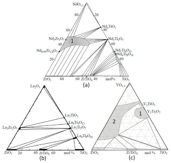
Figure 3.
Systems NdO1.5–TiO2–ZrO2 (a), La2O3–TiO2–ZrO2 (b), and YO1.5–TiO2–ZrO2 (c) at 1350–1500 °C. Fields of pyrochlore (1) and oxide with a fluorite structure (2) are shown [65,74,75,76].
The replacement of Nd3+ by La3+ has a weak effect, whereas a decrease in the ionic radius from Nd3+ to Sm3+, Gd3+, and Y3+ leads to a more significant change [74,75,76,77]. The La2O3–TiO2–ZrO2 system also contains La2TiO5 (LT), La4Ti3O12 (L2T3), La2Ti2O7 (LT2), La4Ti9O24 (L2T9), La2Zr2O7 (LZ2), ZrTiO4 (ZT), ZrO2 (Z), and TiO2 (T). Systems with Nd2O3 and La2O3 are similar in terms of their set of phases; however, in the system with lanthanum, the pyrochlore region is smaller. When the large ions La3+ and Nd3+ are replaced by Y3+, Y2Ti2O7 (pyrochlore) is formed, and a cubic oxide ((Zr,Y)O2−x) with a fluorite structure appears. The structure of Y2TiO5 is cubic (sp. group Fm-3m), but Nd2TiO5 and La2TiO5 have orthorhombic symmetry (sp. group Pnma). A feature of Nd and La titanates is slight variations in composition, although the Ti–REE ratios in them are close to the values in the formulas (Figure 3). At 1350 °C, the LT2, L2T3, and LT phases contain less than 2 mol.% ZrO2, the ZrO2 content in L2T9 is higher and equals 4 mol.%, and the contents of La2O3 and ZrO2 in La2Zr2O7 reach 35 mol.% and 69 mol.%, respectively (Table 4, with details in [75]). The isomorphism of La3+ in ZrO2 and ZrTiO4 is limited to 1 mol.% La2O3. In (Ti,Zr)O2 and (Zr,Ti)O2, high contents of ZrO2 and TiO2 (12–14 mol.%) are found, and the Zr–Ti ratio in ZrTiO4 varies from 1.4 to 0.9.
Table 4.
Variations in the phase composition (mol.%) in the La2O3–TiO2–ZrO2 system.
4. Actinide Wasteforms in the REE2O3 (Nd2O3)–ZrO2–TiO2 System
Below, we consider the issue of matrices for the REE–actinide fraction in the REE2O3 (Nd2O3)–ZrO2–TiO2 system, taking into account the data of references [65,78] and the previous results from [62,70,71,72,73,74,79,80,81,82]. About 30 samples were synthesized by cold pressing and sintering (CPS) of the oxide mixture at 1400–1550 °C and by induction cold crucible melting (ICCM). These samples were analyzed on a Rigaku D/Max 2200 X-ray diffractometer (XRD, Cu Kα,) (Rigaku, Tokyo, Japan) and in a JSM–5610LV scanning electron microscope with a JED–2300 (JEOL, Tokyo, Japan) energy-dispersive spectrometer (SEM/EDS). To determine corrosion resistance, their interaction with water and brines was studied at 90–240 °C for 30–143 days. After the tests, the solutions were analyzed for REE content; to determine the colloidal form, they were filtered through membranes with pore sizes of 450, 200, 100, and 25 nm. The compositions of the solution and its filtrates were analyzed using an inductively coupled plasma–mass spectrometer (XII ICP-MS, Thermo Fisher Scientific Inc., Waltham, MA, USA). Samples were irradiated with 1 MeV Kr2+ (flux density of 1012 ions/(cm2 × s)) using the accelerator at Argonne National Laboratory in the US at T = 50–1023 K. Some samples were irradiated with 4.5–5 MeV electrons at JSC SRC “RIAR” (Russia) with a subsequent study of their structure and hydrolytic stability.
As before, we will use mineral names or designations for the phases based on their formulas, where Nd2O3, ZrO2, and TiO2 are replaced by N, Z, and T, respectively. In the Nd2O3–TiO2–ZrO2 system, there are [65,78] the following phases: Nd2(Ti,Zr)2O7 (NTZ) with a pyrochlore structure, TiO2 (T), ZrTiO4 (ZT), and tetragonal ZrO2 (Z). Nd titanates are represented by Nd2TiO5 (NT), Nd2Ti2O7 (NT2), Nd2Ti4O11 (NT4), and Nd4Ti9O24 (N2T9). In [60], the identities of Nd2Ti4O11 and Nd4Ti9O24 were proven, and the Nd2Ti3O9 (NT3) phase was found. The largest field in the Nd2O3–ZrO2–TiO2 diagram is occupied by pyrochlore; smaller variations in composition are characteristic of Nd4Ti9O2 (Figure 3a), which makes these phases promising hosts for the REE–actinide fraction. Data on samples prepared by CPS or ICCM routes composed of the pyrochlore or orthorhombic REE titanate are discussed below.
4.1. Samples of the Composition (REE)2(Zr,Ti)2O7 with a Pyrochlore Structure
To check the pyrochlore region boundaries, samples whose composition points lie on the REE2Zr2O7–REE2Ti2O7 line (Figure 4) were studied. They were obtained by sintering for 5 h at 1400 °C (Zr–Ti ratio ≤ 1) or 1550 °C (Zr–Ti ratio > 1). The batch charge was prepared from TiO2, ZrO2, and REE2O3 in quantities corresponding to the formula REE2Zr2−xTixO7, where “x” varies from 0 (sample T0) to 2 (T20), with a step of 0.1 or 0.2. The proportions of REE oxides corresponded to the contents in the SNF and were in wt.% as follows: 11.8 La2O3, 23.0 Ce2O3, 10.7 Pr2O3, 38.9 Nd2O3, 8.1 Sm2O3, 1.3 Eu2O3, 1.5 Gd2O3, and 4.7 Y2O3. Up to x = 0.8 (T0–T8), the samples consist of pyrochlore; however, at a higher titanium content, monoclinic REE titanate with a perovskite structure appears. This phase becomes the main one at x > 1.2, i.e., in samples T12–T20. The content of total REE oxides in titanate is approximately 10% higher than in pyrochlore, as the values are 65 and 55 wt.%, respectively (Table 5).
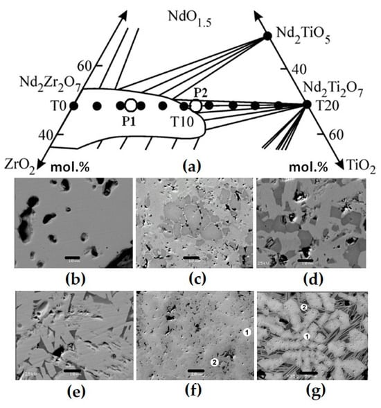
Figure 4.
Part of the NdO1.5–ZrO2–TiO2 diagram (a) and the compositions of ceramics obtained by sintering (T0–T20, dark circles) or melting (rings), and SEM images of samples T0 (b), T15 (c), T18 (d), T20 (e), P1 (f), and P2 (g). Light—pyrochlore; dark—REE titanate. Data are provided according to [71,81]. Scale bars are 10 (b–e), 20 (f), and 50 (g) µm.
Table 5.
Compositions (wt.%) and formulas of the pyrochlore (p) and monoclinic phases (m).
Samples P1 and P2 (Figure 4) were obtained using the ICCM method with neodymium (P1) or a mixture of lanthanum, cerium, and gadolinium (P2) as waste simulants. The synthesis was carried out in air with a zirconium ring placed in the batch to start the melting. After the melt was formed and the batch was loaded, it was kept melted for 0.5 h, and then the setup was turned off for cooling and the material formed a ceramic block. The composition of sample P1 (formula Nd2Zr1.5Ti0.5O7) lies in the pyrochlore field (Figure 4). According to XRD and SEM/EDS data, it is composed of pyrochlore, the composition of which varies within the sample (Table 6). Light areas are enriched in Zr (on average 41.5% ZrO2) compared to dark ones (36.6%), although the Nd2O3 contents are similar.
Table 6.
Phase compositions (wt.%) and atomic quantities of elements based on 7 O2−.
The composition of sample P2, wt.%, is 14.6 TiO2, 22.4 ZrO2, 14.9 La2O3, 15.0 Ce2O3, and 33.1 Gd2O3, its formula is (La0.5Ce0.5Gd)TiZrO7, and it is located at the edge of the pyrochlore field. Pyrochlore dominates in it (85–90%), although REE titanate is also present (Figure 4). From the center to the edges of the pyrochlore grains, the concentration of zirconium and lanthanum decreases (Table 6), and that of gadolinium and titanium increases. Pyrochlore is enriched in ZrO2 and Gd2O3 but contains less La2O3 and Ce2O3 relative to REE titanate. REE titanate is located between the pyrochlore grains, which indicates its late formation. Another phase of the composition, wt.%, is 18.7 TiO2, 5.1 ZrO2, 26.7 La2O3, 15.0 Ce2O3, 13.5 Gd2O3, 18.6 SiO2, and 2.4 Fe2O3 with the following ratio of REEs: (Ti + Zr + Fe), while Si is close to the mineral perrierite (La,Ce)2Ti2Si2O11. It is formed due to the partial dissolution of the crucible coating, which explains the localization in the marginal parts and the presence of Si and Fe.
4.2. Samples of the Composition (REE)4(Zr,Ti)9O24 with a Pyrochlore Structure
Samples with the (REE)4Ti9O24 phase containing 48 wt.% of the REE–actinide fraction were obtained by sintering and melting–crystallization. The points of the bulk compositions of the samples lie near or in the field of this phase, as shown in Figure 3a. Sample RT-1 (Figure 5, Table 7), composed of REE titanate (light) and titanium oxide with a rutile structure (dark), was obtained by sintering the following mixture for 4 h at 1375 °C, wt.%: 52 TiO2, 45 Nd2O3, and 3 Sm2O3 (formula Nd3.75Sm0.25Ti9O24). Several samples (IM-1, IM-2, RT-2, and MPM-1) were obtained by the ICCM method at 1500 °C. They are composed of orthorhombic titanate and rutile, the proportion of which depends on the composition of the batch and varies from 10 to 50% (Figure 5). Rutile contains 3–8 wt.% ZrO2, where Zr4+ replaces Ti4+ due to the close radii (0.72 Å and 0.61 Å). The formula of REE titanate is calculated for 24 O2−, and the sum of Ti4+ and Zr4+ is close to 13 (Table 7). It contains up to 3 wt.% ZrO2. Analysis of the samples in a high-resolution electron microscope (Figure 5f) confirmed the orthorhombic symmetry (sp. gr. Fddd) and the unit cell parameters, Å: “a” = 14.0, “b” = 35.5, and “c” = 14.6.
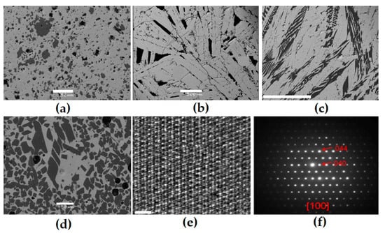
Figure 5.
SEM images of samples obtained by sintering (RT-1 (a)) or melting (IM-9 (b), RT-2 (c), and MLM-1 (d)) and electron diffraction patterns for orthorhombic rare earth titanate in the MLM-1 sample (e,f). 1: orthorhombic rare earth titanate (light); 2: rutile (dark). Scale bars are 50 (a,d) and 500 (b,c) microns or 2 nm (e).
Table 7.
Compositions (wt.%) and formulas of the rare earth titanate (dash—element not entered).
Samples obtained via melting have larger grain sizes than those obtained by sintering. The melting temperatures of samples with orthorhombic titanate are about 1500 °C. This is 100–250 °C lower than that of Ti-Zr pyrochlore, which simplifies the synthesis.
5. On the Pseudo-Ternary Nature of the Nd2O3–ZrO2–TiO2 System
The Nd2O3–ZrO2–TiO2 system was previously considered to be ternary; however, in the case of the partial reduction of Ti4+ (TiO2) to Ti3+ (Ti2O3), it becomes quaternary. A sample of the composition (mol.% 21 Nd2O3, 16 ZrO2, and 63 TiO2) was synthesized by melting in a glass–carbon crucible [82]. According to the data [65,78], it should consist of Nd2Ti2O7 and ZrTiO4; however, according to the results of the X-ray diffraction and SEM/EDS studies, the sample is composed of two Nd titano-zirconates of different colors and compositions (Figure 6, Table 8) and rutile. Electron back-scatter diffraction (EBSD) confirmed the structure of pyrochlore for the light phase and zirconolite for the dark one (Figure 6). When the melt interacts with the glass–carbon crucible, the following reaction occurs: 2Ti4+O2 + C = Ti3+2O3 + CO. Ti3+ ions serve as charge compensators during the following exchange: Nd3+ + Ti3+ → Ca2+ + Ti4+, which leads to the formation of zirconolite (ideally CaZrTi2O7), in which Ca2+ is fully replaced by Nd3+. Based on the composition of the phases (Table 8), their formulas were calculated with Ti4+ only and taking into account Ti3+. Reducing conditions are necessary for Ti3+ appearance, but only Ti4+ is stable at the synthesis in air, and the system is ternary.
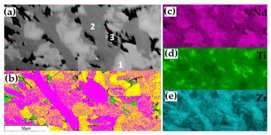
Figure 6.
SEM image ((a) 1-pyrochlore, 2-zirconolite, 3-rutile), EBSD map (b) yellow—pyrochlore, purple—zirconolite, green—rutile)), and distribution of Nd (c), Ti (d), and Zr (e) in the sample with Ti3+.
Table 8.
Compositions (wt.%) and phases formulae; for zirconolite, the option with Ti3+ is shown.
6. Behavior of the Matrices with a REE–Actinide Fraction in Hot Aqueous Solutions
Along with the waste capacity, a very important characteristic of actinide matrices is their resistance to leaching. Several standard test protocols have been developed to determine this parameter [25,26,28,36,39,83]. The behavior of pyrochlore has been studied in static and dynamic tests [64,66,68,73,84,85,86,87]. The normalized leaching rate of U and REE from titanate pyrochlore under near-neutral conditions is 10−4–10−5 g/(m2 × day), and it increases by an order of magnitude in alkaline (pH > 9) or acidic solutions (pH < 5). This is three orders of magnitude lower compared to the leaching rates of HLW glasses under similar conditions [88,89]. The rates of actinide and REE leaching from zirconate pyrochlores are lower than from titanate ones. For pyrochlore La2Zr2O7 in static tests in water and alkaline solution (pH = 10) at 90–150 °C, the leaching rates of La are below 10−4 g/m2 × day, and for Zr, they are equal to 10−6 g/(m2 × day) [90,91,92]. The rate of plutonium leaching from titanate pyrochlores before their amorphization (MCC-1, water, 90 °C, 14–28 days) varies from ~10−2 to 10−4 g/(m2 × day). The spread of values is probably due to the presence of other phases in addition to pyrochlore in the samples. After amorphization, the rate of Pu leaching increases to 7 × 10⁻²–9 × 10⁻³ g/(m2 × day). Leaching of Cm from pyrochlore (Gd,Cm)2Ti2O7 after amorphization increased from 10−2 to 2 × 10⁻¹ g/(m2 × day) [89,93,94]. For pyrochlore (Gd,Cm)2(TiZr)O7, leaching rates as low as 1.7 × 10⁻² and 4.7 × 10⁻² g/(m2 × day) were obtained [94]. Amorphization increases the rate of actinide leaching by a factor of 3–10, and, rarely, reaches 50 times the original rate [66,87,89,93,94,95,96,97]. Therefore, in runs with short-lived actinides (244Cm), the rate of actinide leaching increases due to phase amorphization, as well as due to an increase in the acidity of the solution to pH = 4 due to its radiolysis.
Studies of the corrosion resistance of the REE2Ti2O7 and REE4Ti9O24 phases are rare [64,73,79,80,98,99]. The leaching rates of La and Nd (95–240 °C, water, brine, 30–143 days) are close to those of pyrochlore and vary from 10−3 to 10−5 g/(m2 × day), which corresponds to the dissolution of a matrix layer a few microns thick in a year. Taking into account previous studies [66,72,73,80], we conclude that pyrochlore and Nd titanates are rather resistant to corrosion in hot waters. Incongruent dissolution with a higher leaching rate of REEs and actinides compared to Ti and Zr is typical for them. This leads to the formation of a surface layer, tens of nm thick, enriched with these elements, which complicates the leaching of actinides [64,92,96]. After 40 days of contact of the pyrochlore with a solution of 0.5 M CaCl2 + 0.5 M NaCl (T = 200 °C), no changes were detected in the SEM (Figure 7).
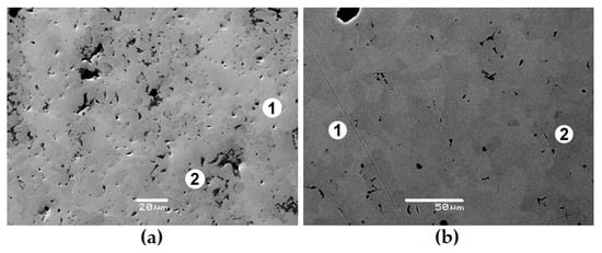
Figure 7.
Images of sample P1 before (a) and after contact with brine (b); 1,2 indicate pyrochlore grains of a different color and composition (Table 6), from [73].
7. Behavior of the Matrices with a REE–Actinide Fraction Under Irradiation
The sources of radiation in the HLW forms are β- and α-decay, γ-radiation, and spontaneous fission of actinides (Table 9 and Table 10). The disordering of the crystalline structure is mainly due to the formation of α-particles and heavy recoil nuclei during actinide decay. α-particles (He2+ with an energy of 4.5–5.5 MeV) account for up to 98% of the decay energy. At the end of a range of 10–20 μm, they collide with hundreds of atoms, knocking them out of their original position (Table 10, with additional data in [100]). Recoil nuclei with an energy of 70–100 keV collide with 1000–2000 atoms on a path of 10–40 nm. The role of beta particles, gamma radiation, and neutrons in this aspect is small. The influence of spontaneous fission of heavy actinides increases starting from 244Cm, but this effect is weak due to their low content.
Table 9.
Composition and properties of a mixture of Am and Cm isotopes isolated from a t of SNF of a PWR-type reactor with a burnup of 50 GW × day after 6 years of storage.
Table 10.
Radiation effects in solidified forms of HLW according to references [25,50,93,95,97,101].
The synthesis of actinide matrices is a labor-intensive and complicated process due to the need for protection from radiation, as well as the high cost of Pu, Am, and Cm isotopes. To study radiation damage, simulation techniques are typically used, such as irradiation with neutral or charged particles [25,26,28,50,66,68,69,85,86,93,97,99,101,102,103,104,105,106,107,108,109,110,111]. These techniques allow radiation doses that a matrix with real HLW will accumulate over many thousands of years to be achieved in a very short time (minutes). The most common method for studying the radiation resistance of actinide matrices is irradiation with heavy ions. The goal of such works is to determine the critical radiation dose (Dcr), leading to amorphization of the structure, and the critical temperature (Tcr), above which amorphization does not occur at any dose. The higher the first value and the lower the second, the more resistant the phase structure is to radiation. The main advantages of irradiation with ions are its short duration; lack of induced activity, which simplifies the study of matrices; the fact that the critical doses and temperatures of all phases in the sample can be determined simultaneously; and the fact that disordering is observed in an electron microscope during irradiation. Matrices are usually irradiated with 1 MeV Kr+/2+, in which case the amorphization doses in units of displacements per atom (dpa) are close to the values during the decay of actinides [66,68,87,88,89,93,95,97,101].
In the REE2O3–ZrO2–TiO2 system, the phases with the pyrochlore structure have been intensely studied [66,95,97,101,102,103,104,105], there is a lot of data on the behavior of REE2TiO5 and REE2Ti2O7 under irradiation [69,87,97,101,102,103,104,105,106,107,108,109,110,111], and for REE4Ti9O24 there are scarce data [111]. For the A2B2O7 phases (A = La–Lu, B = Ti, Zr), the critical temperature decreases (the resistance to radiation increases) upon transition from REE phases with the perovskite structure to compounds with the pyrochlore structure [103,104,105]. We studied samples consisting of pyrochlore only (T0), as well as pyrochlore and monoclinic titanate (T15, T18, T20), and orthorhombic REE titanate and rutile (IM-2, IM-9), the compositions of which are given in the Table 5, Table 6 and Table 7. When irradiated with 1 MeV Kr2+ to a dose of 25 × 1014 ion/cm2, the structure of the zirconate phase is transformed into the fluorite lattice (Figure 8), and for the monoclinic perovskite phase, amorphization is already observed at 2.5 × 10¹⁴ ion/cm2. This proves the resistance of zirconate pyrochlore (T0) to irradiation. Zirconate–titanate pyrochlore (T15) has intermediate values of Dcr, while low resistance is typical for monoclinic and orthorhombic rare earth titanates (Figure 9). For a specific type of irradiation, the Tcr is constant (Figure 9), and the Dcr increases with the rise in temperature, since the amorphous state is unstable. Heating leads to the healing of defects, so higher doses of irradiation are required to disorder the atoms in the lattice with increasing temperature.
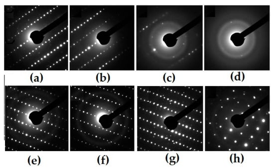
Figure 8.
Electron diffraction patterns for pyrochlore- (T0, a–d) and perovskite-type monoclinic REE titanate samples (T18, e–h) before (a,d) and after irradiation by 1 MeV Kr2+, to dose 1014 ions/cm2: 2 (b), 6 (c), 25 (d), 1.3 (e), 1.9 (f), and 2.5 (h).
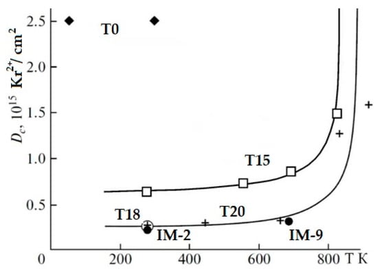
Figure 9.
Amorphization doses of Ti-Zr (T15) pyrochlores, monoclinic (T18, T20), and orthorhombic (IM-2, IM-9) titanates under irradiation with 1 MeV Kr2+. The structure of zirconate pyrochlore (T0) is transformed at irradiation into a defective fluorite-type lattice [97,105,111].
The composition of A1.94Ti2.00O6.92 (where A is a mixture of REE as in HLW) has the following Dcr and Tcr values: Dcr = 2.5 × 10¹⁴ Kr2+/cm2, and Tcr = 900 K. Critical doses (T = 298 K) of the phases Nd3.96(Ti8.92Zr0.12)O23.94 and REE3.95(Ti8.71Zr0.34)O24.01 (REE = 0.43La + 0.92Ce + 0.30Pr + 1.63Nd + 0.25Sm + 0.10Eu + 0.09Gd + 0.23Y) are determined as 3 × 10¹⁴ Kr2+/cm2 (0.2 dpa), and their Tcr is 900 K. Similar values were obtained for monoclinic titanates: for La2Ti2O7, the critical dose is defined as 2.16 × 10¹⁴ Kr2+/cm2, while the critical temperature, Tcr, is 840 K.
A sample consisting of Nd4(Ti,Zr)9O24 and rutile (Ti,Zr)O2 was obtained by the ICCM method [99] and irradiated with an electron beam (energy 4.5–5 MeV, beam power 20 kW, current 17 mA) to a dose of 5 × 10⁹ Gray. Irradiation did not affect the cell parameters of the neodymium titanate and rutile phases (Figure 10), but the leaching rate of Nd and Ti from the irradiated sample with water on the 28th day increased from 10−5 to 10−4 g/(m2 × day).
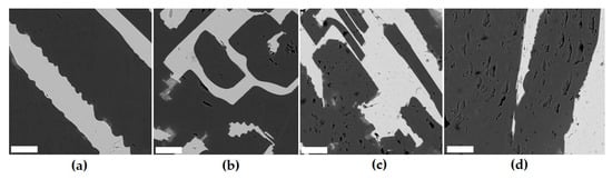
Figure 10.
SEM images of the sample before (a) and after irradiation to a dose of 107 (b), 5 × 10⁸ (c), or 5 × 10⁹ Gray (d). Light is orthorhombic Nd titanate, dark is rutile. Markers are 20 µm.
When irradiated with 1 MeV Kr2+ ions, the critical temperatures of the Nd phases change from 135 and 685 K for the pyrochlores Nd2Zr2O7 and Nd2Ti0.8Zr1.2O7 to 918 K for the perovskite Nd2Ti2O7 and 1200 K for Nd2TiO5, respectively [108]. At a disposal facility, temperatures of 300–350 K (in mines) or 400–550 K (in deep boreholes) are expected, so only pyrochlores with a Zr–Ti ratio > 1 will retain crystallinity, while the remaining compositions will be amorphized due to actinide decay. Nevertheless, the actinide leaching rate increases by only one order of magnitude in this case. Radiation has direct (amorphization) and indirect (increase in acidity during radiolysis, heating) effects on the properties of actinide matrices and their behavior in the disposal facility. The influence of amorphization on leaching rates is usually limited to less than one order of magnitude. The acid pH of the solution is quickly neutralized by interaction with the container materials and the bentonite-based buffer. Temperature causes an increase in the leaching rate, but slows down the process of disordering the structure, preserving the original properties of the matrix. In general, radiation resistance is significantly less important for the selection of matrices than their corrosion resistance. Deep groundwater is represented by brines, so the leaching resistance of matrices must be studied under conditions close to these settings. Calculations were made of the thermal field of a borehole repository for the REE–actinide fraction. The estimates have considered the container diameter, waste content, and holding time before disposal [53]. The decay of minor actinides (Am, Cm) will result in the heating of the wasteforms of up to 300–500 °C for decades, while REE decay has a rather short-term effect on the matrix heating. With a waste content of 30 wt.% in the immobilizing matrix, the temperature increase in 10 years will be less than 40 °C.
8. On the Synthesis of Matrices in the REE2O3 (Nd2O3)–TiO2–ZrO2 System
A material with the best properties will not become a matrix of real HLW unless it can be effectively obtained in the required volumes remotely. Given the high radiation, the availability of industrial wasteform production technology is especially important [15,28,29,30,31,32,33,34,35,36,37,39,86,112,113,114,115,116]. Due to the absence of such a technology, the ceramics Synroc and the super-calcine proposed in the 1970s did not find practical application [25,26,28,114]. Only now, 50 years later, is the technology for producing Synroc by hot pressing close to implementation at a radiochemical plant in Australia [115]. The technologies already tested on real actinide-containing materials (waste) include melting in electric furnaces or induction crucibles, and sintering [15,37,39,86,116]. Melting has been used for over 40 years at the radiochemical plants in France, UK, USA, Russia and other countries to vitrify high-level waste [25,26,27,28,29,30,31,32,33,34,35,36,37,112,113], while sintering—for the synthesis of fuel with Pu, Np, and Am—is carried out using the MOX, REMIX, and MNUP processes [117,118,119]. The cold pressing and sintering route was developed to produce Synrocs and pyrochlore-based ceramics for weapons-based plutonium [15,26,28,39]. The hot pressing method was proposed in Australia to produce Synroc ceramics [25,114,115].
Melting methods are preferable to industrial technologies, as they are less sensitive to the quality of the batch and do not require the use of pressure. In the 1970s, induction melting technology was proposed for the vitrification of high-level waste [25,26,27,28,29,30,31,32,33,34,35]. Its advantages are a contactless energy supply and skull melting under active hydrodynamic conditions. In Russia, research has been conducted for over 20 years on the synthesis of induction melting in a cold crucible, as well as on the ICCM of vitreous matrices and ceramics, including Synroc, zirconolite, pyrochlore, murataite, brannerite, etc. [80,81,86,99,120,121]. Abroad, the ICCM method is widely used to obtain ceramic and glass–ceramic forms with HLW simulants [28,30,39,122,123,124,125]. It allows for obtaining matrices of the REE–actinide fraction at temperatures up to 2200 °C, although high temperatures require large energy costs. The REE zirconates are refractory phases, while the liquidus temperatures are above 2000 °C. In titanate systems, the melting temperatures are lower: for La2Ti2O7 and Nd2Ti2O7, they are 1790 and 1650 °C, but for Nd4Ti9O24 and the eutectic mixture composed of 85 mol.% Nd4Ti9O24 and 5 mol.% TiO2, they are below 1500 °C (Table 3), which makes ICCM a promising technique for their manufacture.
9. Discussion
The prevention of the negative ecological impact of nuclear power waste is a fundamental scientific task and a practical problem. The main threat is associated with high-level waste containing long-lived actinides and fission products. Two approaches have been proposed to solve this problem, namely P&T (partitioning and transmutation) and P&C (partitioning and conditioning) [58,125]. The P&C approach is being developed by physicists and radiochemists; it is based on the separation of radioisotopes and their conversion into stable and short-lived isotopes upon neutron irradiation. This scheme includes the separation of HLW onto radionuclides or their groups, transmutation in a fast neutron flux, and disposal of the remaining waste. The first information on transmutation dates back to 1964 [126,127] and concerned fission products (90Sr, 137Cs). The transmutation of actinides in thermal light water-cooled reactors (LWRs) was proposed in 1972 [128], but later fast neutron reactors and subcritical installations, such as accelerators, were chosen for this purpose, as these are more promising [129,130,131]. The alternative approach (P&C) is being developed by geologists (mineralogists, geochemists), materials scientists, and some radiochemists; it involves the inclusion of waste in matrices, followed by their disposal. This method is more economical, since it requires less isotope separation and there is no need to build very complex expensive installations for the deep partitioning of HLW, fuel fabrication, multiple irradiations, and SNF reprocessing.
The purpose of transmutation is to reduce the environmental hazard posed by SNF and HLW [11,12,41,43,59,132,133,134,135,136,137,138,139,140,141] in order to achieve radiation (radioecological) equivalence of HLW and the uranium ore used to manufacture nuclear fuel as quickly as possible. Calculations have shown that extraction and transmutation of 99.9% of actinides reduces this time to 100–300 years, which eliminates the need to construct deep geological disposal facilities. The obvious mistake in this calculations is connected with the assumption of complete dissolution of HLW and uranium ore in water and the subsequent entry of radionuclides into the human body [142]. The shortcomings of the radiation equivalence concept are discussed in [143,144]. Many studies have noted the difficulties in implementing industrial separation of radionuclides, MA-loaded fuel production, its irradiation in fast reactors, and SNF reprocessing to extract actinides again [41,43,58,125,135,136,137,138,139,141,145,146,147].
For the transmutation of minor actinides, installations with accelerators [131,148,149,150] and molten salt reactors [151,152,153,154] are also proposed. The latter do not require actinide separation, but their problems are associated with their high cost and lack of operating experience, as well as the requirement of isotopically pure 7Li, the need to remove fission products, the high corrosive activity of the fluoride melt, etc. [153]. It can be assumed that the announced ambitious task of implementing large-scale transmutation in the first half of the 21st century [149] will not be realized. Due to the need for large volumes of scientific and experimental design work in the field of creating new types of reactors, fuel, and materials, the use of this technology is shifted to the distant future [17]. Another problem with this approach is that in this case, it will be necessary to deal with large volumes of highly active materials for many years, which creates a high risk of accidents, such as the irradiation of personnel and the population. Therefore, the question of using transmutation comes down to the choice between risks and consequences for current (transmutation) and future (disposal of HLW) generations.
The possibility of the geological isolation of actinide-containing waste is beyond doubt. There are over 2000 uranium deposits with an age of many millions of years and total resources of over 10 million t [155]. Numerous data prove the absence of uranium migration in reducing environments, which determines the preservation of uranium ores, as well as uranium and thorium retention, in natural vitreous and crystalline materials for hundreds of millions of years [50,66,85,87,101,156]. Such environments are realized at depths of up to several hundreds of meters. Arguments in favor of long-term conservation of radionuclides include the results of studies of radioactive minerals and ores, laboratory and field experiments, thermodynamic calculations, and computer modelling. The world has already accumulated 30–35 thousand t of vitrified HLW from the reprocessing of SNF (the main volumes are stored in France, Russia, the UK, and the US) [7,15,37,157], which will be disposed of in underground disposal facilities. In countries with an open nuclear fuel cycle without reprocessing of SNF, its geological disposal is also assumed. The protective properties of geological environments are due to the low solubility of radionuclides in water and the high sorption capacity of rocks. This is facilitated by the slow movement of underground waters, which are carriers of radionuclides. A contribution to safety will be provided by sorptive bentonite buffer swelling in water, corrosion-resistant containers, and durable matrices immobilizing nuclear waste. Their main characteristics are high loading for waste, a low leaching rate in water, and the possibility of remote fabrication on an industrial scale.
Extraction and precipitation methods are used to separate liquid HLW onto fractions [13,17,24,38,41,42,43,44,45,46,47,52,125,130,139,157]. In France, a pilot reprocessing of 15 kg of SNF was conducted with the separation of the REE–actinide group of elements [158]. In Russia, a plant for the separation of the Cs-Sr fraction from liquid HLW was in operation from 1996 to 2007, and the separation of the REE–actinide fraction was began there in 1999 [159]. From 1996 to 2003, 1630 m3 of HLW were processed there and 1.73 million Curies of the REE–actinide fraction (Am, Cm) were separated by precipitation of oxalate.
During one year of operation of an LWR with a capacity of 1000 MW, 20 t of SNF are formed. A plant for the reprocessing of 800 t of irradiated fuel generates about 4000 m3 of liquid HLW per year, with 1 m3 of such waste containing up to 90 g of Am and Cm. A fleet of reactors with a total capacity of 100 GW(e), as in the USA or Western Europe, produces up to 3 t of minor actinides per year, with almost equal amounts of Np and the sum of Am and Cm; the annual accumulation of the REE–actinide fraction during the reprocessing of SNF will be about 30 t. In France, 350–400 billion kWh of electricity are produced per year at nuclear power plants [160]. This leads to an annual production of SNF containing up to 300 kg of Am and 150 kg of Cm [43], and the mass of the REE–actinide fraction will be about 10 t. In 2022, Russian NPPs generated more than 220 billion kWh of electricity [161], or ~60% of that produced in France.
In the case of the reprocessing of all discharged SNF and fractionation of HLW, up to 6 t of the REE–actinide fraction will be formed per year. Its immobilization will require 10–20 t (2–4 m3) of matrix with a 50–25 wt.% REE–actinide fraction. According to estimates, a cluster of horizontal boreholes drilled from a vertical wellbore, known as SuperLAT technology (Figure 11), will accommodate up to 1000 t of SNF [162] or 500 t of HLW.
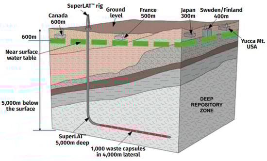
Figure 11.
Horizontal wells of the SuperLAT system compared to mined repositories [163].
Placing solidified actinide waste in deep disposal facilities is obviously less dangerous than injecting liquid radioactive waste (LRW), which has been practiced in Russia for about 60 years [164,165,166]. This technology involves injecting it into porous collectors at depths of 180 to 500 m, isolated from aquifers by clays. The total volume of LRW by 2014 exceeded 60 million m3, and the activity was 7 × 10¹⁹ Bq or ≈ 2 billion Curie. The actinide content in water at a distance of 100–150 m from the injection wells decreases by 104, which is 106 times compared to the initial values, i.e., the bulk of the radionuclides was quickly precipitated.
The very low migration ability of actinides in underground water at reducing conditions, which are already dominant at depths of the first hundreds of meters, is evidence in favor of the geological isolation of actinide wastes [125,167,168]. Programs for the geological disposal of HLW exist in many countries, including Russia [22,23,24,167,168,169,170,171,172]. The main contribution to human exposure will be made not only by the actinides, but also by long-lived fission products (79Se, 99Tc, 129I) due to their weak sorption by rocks and high migration rates in the geological environment [168,171]. Along with the traditional ultimate disposal of SNF and solidified HLW in mine-type disposal facilities [18,19,20,21,22,23,24,172], more and more attention is being paid to deep boreholes, which are vertical, with a depth of 3 to 5 km [173,174,175], or initially vertical and then horizontal, at depths of 1–3 km [162,163,176,177,178].
10. Conclusions
Two technologies have been proposed for handling actinide-containing fractions: transmutation and immobilization. The purpose of transmutation is to reduce the amounts of long-lived radionuclides by irradiation in nuclear reactors or accelerators. The first works on this topic devoted to fission products are about 60 years old [126]; this method was first proposed for actinides 50 years ago [128]. At practically the same time, the study of crystalline matrices for HLW began [25]. The principles of transmutation are developed theoretically [41,137,179], and experiments on irradiation of targets with actinides have been conducted [140]. Practical implementation of the approach faces a lot of technical difficulties and high costs. Reducing the amounts of radionuclides requires multiple irradiations of actinide-loaded fuel [43]. Due to the increased amounts of heavy actinides, mainly 244,245Cm [179], the irradiated targets will possess high levels of radioactivity, neutron fluxes, and temperature, which complicate reprocessing and the production of new fuel. For these purposes, fast neutron reactors are needed, in which the actinide fission dominates over neutron capture. Reasonable doubts on the benefits of minor actinides transmutation are discussed in [180]. As can be seen, many questions concerning the technical feasibility of the effective transmutation of minor actinides, raised more than 30 years ago [181], are still relevant. The extraction and accumulation of minor actinides (Am, Cm) with relatively low (tens kg) critical masses is a threat to the policy of nuclear weapons non-proliferation [182,183].
Another approach to solving the problem of long-lived radionuclides is to incorporate them into stable matrices for placement in deep geological disposal facilities. This approach’s feasibility is demonstrated by the study of natural analogues of matrices, i.e., minerals that have retained actinides (Th,U) and REEs with properties similar to minor actinides for millions of years [50,85,87,184,185,186]. The presence of geological environments with a very low actinide migration is demonstrated by data on the preservation of U and Th deposits, their behavior in the natural nuclear reactor Oklo (Gabon), and studies on the solubility and sorption of actinides in laboratories and in natural (field) tests. This research is supported by data on volcanic rocks confining uranium and thorium for over 140–145 million years [156].
Let us summarize the analysis of the phases of the REE2O3–ZrO2–TiO2 system as applied to the problem of REE–actinide fraction immobilization. It is known that Nd3+ serves as an analogue of trivalent actinides (Am, Cm); therefore, the Nd2O3–TiO2–ZrO2 system is relevant when searching hosts for REE–MA. It contains Nd2(Zr,Ti)2O7−x, Nd2TiO5, Nd2Ti2O7, Nd2Ti3O9, and Nd4Ti9O24 phases, containing from 48 to 73 wt.% Nd2O3. Pyrochlore Nd2(Zr,Ti)2O7−x and titanate Nd4Ti9O24 are of the greatest interest as matrices: their stability fields (impurity content) are larger than those of other Nd titanates. With an excess of titanium, an additional phase of rutile (TiO2) is formed, as a result of which the melting temperature decreases to 1450–1500 °C, which facilitates synthesis. Unlike pyrochlore, the Nd4Ti9O24 compound has no analogues in nature. The content of Nd2O3 (actinide imitator) in it varies from 48 wt.% (only Nd4Ti9O24) to 35 wt.% (70% Nd4Ti9O24 and 30% rutile). The leaching rates of actinides and REE from Ti-Zr pyrochlore and REE titanates matrices in a wide range of temperatures (50–240 °C), compositions, and pH of solutions (water, brines) varied in the range of 10−3–10−5 g/(m2 × day) and decreased with increasing interaction time. This is due to the formation of a thin surface layer enriched with zirconium and titanium, which prevents the release of REE and actinides into the solution. As for the other types of matrices [187], the leaching rate in the first days is determined by their solubility; then, due to the formation of an surface layer of alterations, the mode changes to diffusion exchange with low velocity.
Phases of the Nd2O3–TiO2–ZrO2 system are considered as matrices for isolating Pu and the REE–actinide fraction [62,65,68,188]. In addition to Ti-Zr pyrochlore, Nd4Ti9O24 is of interest due to its higher content of impurities (Ca2+, Zr4+, U4+) compared to Nd2TiO5 and Nd2Ti2O7. With an excess of titanium, rutile (TiO2) is formed, which reduces the melting temperature by 200–300 °C, which facilitates the synthesis of such a composite matrix.
Durable stable crystalline phases hosting long-lived radionuclides might be components of integral composite systems containing both crystalline and vitreous nuclear wasteforms. The vitreous systems are not necessarily limited to the B-Si and Al-P glasses currently in use [8,37,142] and may include Fe-P, Al-Si, Fe-Pb-P, and other materials known for their high durability [39,189,190,191]. There is a notable trend to use durable composite materials containing both crystalline and vitreous phases in nuclear waste immobilization practices. The content of the crystalline phases is now being increased in the glass formulations used for nuclear waste vitrification [116,192,193,194], which is schematically shown by the red arrow originating in the left side of the diagram (Figure 12). It is worth noting that the first industrial plant which uses hot pressing in Australia is now designed to synthesize composite materials with Synroc-type crystalline and mineral-like phases distributed within a glass matrix, together forming a durable glass–crystalline material [115,194,195,196,197].
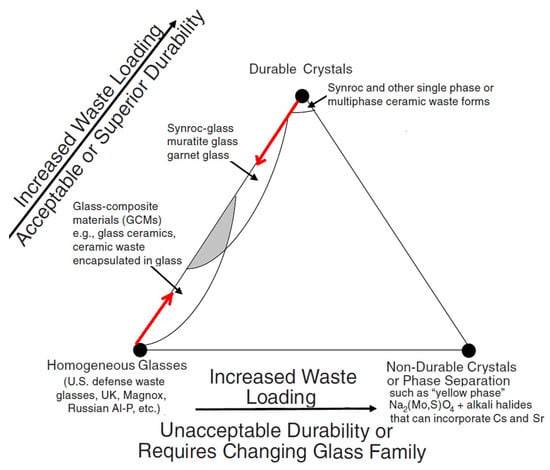
Figure 12.
Composite glass–crystalline hosts for HLW are shown by the shadowed area [8,39].
Matrices of HLW are currently supposed to be placed at depths of 500–700 m in mine-type disposal facilities or in super-deep (3–5 km) boreholes. For the REE–actinide fraction, the borehole option is preferable; in this case, due to the increase in temperature with depth, the rocks can be heated to 200 °C and even higher values [198]. High temperature slows down the radiation destruction of the crystalline structure of actinide hosts and reduces the effect of amorphization on the leaching of radionuclides. Both the large distance to the surface and low velocity of water movement will also serve as important safety factors for HLW disposal.
Progress in the field of methods for separating HLW [47], their incorporation into matrices [39,196], and recent achievements on geological disposal of the spent nuclear fuel and solidified high-level waste [23,199,200] allows us to expect a solution to the problem of handling the REE–minor actinide fractions within the coming decades. The use of transmutation for this purpose appears to be, essentially, a much more complex technological approach, and requires significantly more financial resources and time for implementation [17].
Author Contributions
Conception, S.V.Y.; methodology, S.V.Y. and M.I.O.; investigation, S.V.Y.; resources, S.V.Y.; sample synthesis, O.I.S.; data curation, S.V.Y., M.I.O. and O.I.S.; draft preparation, S.V.Y. and M.I.O. The authors have read and agreed to the published version of the manuscript. All authors have read and agreed to the published version of the manuscript.
Funding
The study was carried out with financial support from the Ministry of Science and Higher Education of the Russian Federation within the framework of a state assignment for the Institute of Geology of Ore Deposits, Petrography, Mineralogy, and Geochemistry of the Russian Academy of Sciences. The APC was granted by MDPI.
Data Availability Statement
All data are available within the manuscript.
Acknowledgments
The authors thank M.S. Nickolsky for helping in the investigation of the samples.
Conflicts of Interest
The authors declare no conflicts of interest.
Acronyms and Glossary
| Å | angstrom, 10−10 m |
| Al-P | alumina–phosphate |
| B-Si | borosilicate |
| DIAMEX | diamide extraction, French process for MA separations |
| dpa | displacement per atom |
| GW | gigaWatt, 109 |
| GW(e) | gigaWatt of electricity |
| GW × h | gigaWatt × hour |
| HLW | high-level nuclear waste |
| ICCM | induction cold crucible melter |
| keV | thousand electron volt |
| LRW | liquid radioactive waste |
| LWR | light water reactor, generic description for thermal reactors with H2O coolant |
| MA | minor actinide |
| MeV | million electron Volt |
| μm | micrometer |
| MNUP | mixed nitride U-Pu fuel |
| MOX | mixed oxide, usually referring to (U,Pu)O2 fuels |
| nm | nanometer |
| ppm | part per million, or 10−4 wt.% |
| PUREX | plutonium and uranium refining by extraction process used in commercial-scale SNF reprocessing |
| PWR | pressurized water reactor, a variety of light water reactor |
| REEs | rare earth elements |
| REMIX | mixed oxide fuel from unseparated U and Pu isotopes |
| SEM/EDS | scanning electron microscope equipped with an energy dispersive system |
| SNF | spent nuclear fuel, irradiated fuel, also referred to as used nuclear fuel |
| Synroc | synthetic rock, a crystalline wasteform composed of mineral-like phases |
| TODGA | N,N,N′,N′-tetraoctyl-3-oxapentane-1,5-diamide for REE–MA fraction extraction |
| TRUEX | trans-uranium extraction, USA process for MA separation |
| TW | terawatt, 1012 |
| TW × h | terawatt × hour |
| XRD | X-ray diffraction analysis |
References
- Burnett, R.; Chen, H.; Szyszkowicz, M.; Fann, N.; Hubbell, B.; Pope, C.A., 3rd; Apte, J.S.; Brauer, M.; Cohen, A.; Weichenthal, S.; et al. Global Estimates of Mortality Associated with Long-Term Exposure to Outdoor Fine Particulate Matter. Proc. Natl. Acad. Sci. USA 2018, 115, 9592–9597. [Google Scholar] [CrossRef] [PubMed]
- Accelerating Decarbonization in the United States: Technology, Policy, and Societal Dimensions; The National Academies Press: Washington, DC, USA, 2024; p. 822.
- State of Global Air 2024; Health Effects Institute: Boston, MA, USA, 2024; p. 35.
- IEA. Net Zero Roadmap: A Global Pathway to Keep the 1.5 °C Goal in Reach 2023 Update; International Energy Agency (IEA): Paris, France, 2023; p. 224. [Google Scholar]
- IAEA. Energy, Electricity and Nuclear Power Estimates for the Period up to 2050; International Atomic Energy Agency (IAEA): Vi-enna, Austria, 2023; p. 137. [Google Scholar]
- NEA. Meeting Climate Change Targets. The Role of Nuclear Energy; NEA No. 7628; OECD/NEA Publishing: Paris, France, 2022; p. 49. [Google Scholar]
- IEA. Electricity 2024. Analysis and Forecast to 2026; International Energy Agency (IEA): Paris, France, 2024; p. 168. [Google Scholar]
- Ojovan, M.I. Vitrification as a Key Solution for Immobilisation Within Nuclear Waste Management. Arab. J. Sci. Eng. 2024, 1–9. [Google Scholar] [CrossRef]
- IEA. World Energy Investment; International Energy Agency (IEA): Paris, France, 2024; p. 215. [Google Scholar]
- NEA. Transition towards a Sustainable Nuclear Fuel Cycle; OECD/NEA Publishing: Paris, France, 2013; p. 67. [Google Scholar]
- Adamov, E.O.; Asmolov, V.G.; Bolshov, L.A.; Ivanov, V.K. Two-Component Nuclear Power. Bull. Russ. Acad. Sci. 2021, 91, 450–458. (In Russian) [Google Scholar]
- Adamov, E.O.; Kaplienko, A.V.; Orlov, V.V.; Smirnov, V.S.; Lopatkin, A.V.; Lemekhov, V.V.; Moiseev, A.V. Brest Lead-Cooled Fast Reactor: From Concept to Technological Implementation. At. Energy 2021, 129, 179–187. [Google Scholar] [CrossRef]
- Kolupaev, D.N.; Apalkov, G.A. Development and Tasks of Radiochemical Technologies: History and Modern Challenges. Radiochemistry 2023, 65, 132–140. [Google Scholar] [CrossRef]
- Holdsworth, A.F.; Eccles, H.; Sharrad, C.A.; George, K. Spent Nuclear Fuel—Waste or Resource? The Potential of Strategic Materials Recovery during Recycle for Sustainability and Advanced Waste Management. Waste 2023, 1, 249–263. [Google Scholar] [CrossRef]
- Yudintsev, S.V. Isolation of Separated Waste of Nuclear Industry. Radiochemistry 2021, 63, 527–555. [Google Scholar] [CrossRef]
- Wang, L.; Liang, T. Ceramics for High Level Radioactive Waste Solidification. J. Adv. Ceram. 2012, 1, 194–203. [Google Scholar] [CrossRef]
- National Academies of Sciences, Engineering, and Medicine. Merits and Viability of Different Nuclear Fuel Cycles and Technology Options and the Waste Aspects of Advanced Nuclear Reactors; The National Academies Press: Washington, DC, USA, 2023; p. 314. [Google Scholar]
- IAEA. Scientific and Technical Basis for the Geological Disposal of Radioactive Wastes; International Atomic Energy Agency (IAEA): Vienna, Austria, 2003; p. 80. [Google Scholar]
- Ahn, J.; Apted, M.J. (Eds.) Geological Repository Systems for Safe Disposal of Spent Nuclear Fuels and Radioactive Waste; Wood-Head Publishing Limited: Cambridge, UK, 2010; p. 777. [Google Scholar]
- IAEA. Disposal of Radioactive Waste; IAEA Safety Standards Series No. SSR 5; International Atomic Energy Agency (IAEA): Vienna, Austria, 2011; p. 62. [Google Scholar]
- Evans, N.D.M. Geological Disposal of Radioactive Waste: Underpinning Science and Technology. Miner. Mag. 2012, 76, 2865–2871. [Google Scholar] [CrossRef]
- Ewing, R.C.; Whittleston, R.A.; Yardley, B.W. Geological Disposal of Nuclear Waste: A Primer. Elements 2016, 12, 233–237. [Google Scholar] [CrossRef]
- NEA. Management and Disposal of High-Level Radioactive Waste: Global Progress and Solutions; OECD/NEA Publishing: Paris, France, 2020; p. 45. [Google Scholar]
- NEA. Strategies and Considerations for the Back End of the Fuel Cycle; OECD/NEA Publishing: Paris, France, 2021; p. 67. [Google Scholar]
- Lutze, W.; Ewing, R.C. (Eds.) Radioactive Waste Forms for the Future; Elsevier: New York, NY, USA, 1988; p. 778. [Google Scholar]
- Donald, I.W.; Metcalfe, B.L.; Taylor, R.N.J. The Immobilization of High Level Radioactive Wastes Using Ceramics and Glasses. J. Mater. Sci. 1997, 32, 5851–5887. [Google Scholar] [CrossRef]
- Caurant, D.; Loiseau, P.; Majérus, O.; Aubin-Chevaldonnet, V.; Bardez, I.; Quintas, A. Glasses, Glass-Ceramics and Ceramics for Immobilization of Highly Radioactive Nuclear Wastes; Nova Science Publishers: New York, NY, USA, 2009; p. 445. [Google Scholar]
- Donald, I.W. Waste Immobilisation in Glass and Ceramic Based Hosts; Wiley: Hoboken, NJ, USA, 2010; p. 507. [Google Scholar]
- Vienna, J.D. Nuclear Waste Vitrification in the United States: Recent Developments and Future Options. Int. J. Appl. Glas. Sci. 2010, 1, 309–321. [Google Scholar] [CrossRef]
- Jantzen, C.M. Development of glass matrices for high level radioactive waste. In Handbook of Advanced Radioactive Waste Conditioning Technologies; Ojovan, M.I., Ed.; Woodhead Publishing Ltd: Cambridge, UK, 2011; pp. 230–292. [Google Scholar]
- Remizov, M.B.; Kozlov, P.V.; Logunov, M.V.; Koltyshev, V.K.; Korchenkin, K.K. Conceptual and Technical Solutions for the Creation of Vitrification Units for Current and Accumulated Liquid HLW at PA Mayak. Iss. Radiat. Saf. 2014, 3, 17–25. (In Russian) [Google Scholar]
- Vernaz, É.; Bruezière, J. History of Nuclear Waste Glass in France. Procedia Mater. Sci. 2014, 7, 3–9. [Google Scholar] [CrossRef]
- Harrison, M.T. Vitrification of High Level Waste in the UK. Procedia Mater. Sci. 2014, 7, 10–15. [Google Scholar] [CrossRef]
- Vienna, J.D.; Collins, E.D.; Crum, J.V.; Ebert, W.L.; Frank, S.M.; Garn, T.G.; Gombert, D.; Jones, R.; Jubin, R.T.; Maio, V.C.; et al. Closed Fuel Cycle Waste Treatment Strategy; Idaho National Laboratory: Idaho Falls, ID, USA, 2015; p. 146. [Google Scholar]
- Goel, A.; McCloy, J.S.; Pokorny, R.; Kruger, A.A. Challenges with Vitrification of Hanford High-Level Waste (HLW) to Borosilicate Glass—An Overview. J. Non-Crys. Solids 2019, 4, 100033. [Google Scholar] [CrossRef]
- Thorpe, C.L.; Neeway, J.J.; Pearce, C.I.; Hand, R.J.; Fisher, A.J.; Walling, S.A.; Hyatt, N.C.; Kruger, A.A.; Schweiger, M.; Kosson, D.S.; et al. Forty Years of Durability Assessment of Nuclear Waste Glass by Standard Methods. Mater. Degrad. 2021, 5, 61. [Google Scholar] [CrossRef]
- Ojovan, M.I.; Yudintsev, S.V. Glass, Ceramic, and Glass-Crystalline Matrices for HLW Immobilisation. Open Ceram. 2023, 14, 100355. [Google Scholar] [CrossRef]
- Choppin, G.; Liljenzin, J.-O.; Rydberg, J.; Ekberg, C. The Nuclear Fuel Cycle. In Radiochemistry and Nuclear Chemistry, 4th ed.; Elsevier: Amsterdam, The Netherlands, 2013; pp. 685–751. [Google Scholar]
- National Research Council. National Research Council Waste Forms Technology and Performance; The National Academies Press: Washington, DC, USA, 2011. [Google Scholar]
- Petrov, V.A.; Ojovan, M.I.; Yudintsev, S.V. Material Aspect of Sustainable Nuclear Waste Management. Sustainability 2023, 15, 11934. [Google Scholar] [CrossRef]
- IAEA. Implications of Partitioning and Transmutation in Radioactive Waste Management; International Atomic Energy Agency (IAEA): Vienna, Austria, 2004; p. 126. [Google Scholar]
- Kopyrin, A.A.; Karelin, A.I.; Karelin, V.A. Technology of Production and Radiochemical Processing of Nuclear Fuel; Atomenergo-izdat: Moscow, Russia, 2006; p. 576. (In Russian) [Google Scholar]
- CEA. Treatment and Recycling of Spent Nuclear Fuel; Commissariat à L’énergie Atomique (CEA): Paris, France, 2008; p. 175. [Google Scholar]
- IAEA. Assessment of Partitioning Processes for Transmutation of Actinides; International Atomic Energy Agency (IAEA): Vienna, Austria, 2010; p. 96. [Google Scholar]
- NEA. National Program in Chemical Partitioning; OECD/NEA Publishing: Paris, France, 2010; p. 119. [Google Scholar]
- Nash, K.L.; Madic, C.; Mathur, J.N.; Lacquement, J. Actinide Separation Science and Technology. In The Chemistry of the Actinide and Transactinide Elements; Morss, L.R., Edelstein, N.M., Fuger, J., Eds.; Springer: Dordrecht, The Netherlands, 2010; Chapter 24; pp. 2622–2798. [Google Scholar]
- Baron, P.; Cornet, S.M.; Collins, E.D.; DeAngelis, G.; Del Cul, G.; Fedorov, Y.; Glatz, J.P.; Ignatiev, V.; Inoue, T.; Khaperskaya, A.; et al. A Review of Separation Processes Proposed for Advanced Fuel Cycles Based on Technology Readiness Level Assessments. Prog. Nucl. Energy 2019, 117, 24. [Google Scholar] [CrossRef]
- IAEA. Impact of High Burnup Uranium Oxide and Mixed Uranium-Plutonium Oxide Water Reactor Fuel on Spent Fuel Management; International Atomic Energy Agency (IAEA): Vienna, Austria, 2011; p. 82. [Google Scholar]
- Bruno, J.; Ewing, R.C. Spent Nuclear Fuel. Elements 2006, 2, 343–349. [Google Scholar] [CrossRef]
- Ewing, R.C.; Weber, W.J. Actinide Wasteforms and Radiation Effects. In The Chemistry of the Actinide and Transactinide Elements; Morss, L.R., Edelstein, N.M., Fuger, J., Eds.; Springer: Dordrecht, The Netherlands, 2011; Chapter 35; pp. 3813–3889. [Google Scholar]
- Walker, C.T.; Rondinella, V.V.; Papaioannou, D.; Winckel, S.V.; Goll, W.; Manzel, R. On the oxydation state of UO2 nuclear fuel at a burn-up of around 100 MWd/kg HM. J. Nucl. Mater. 2005, 345, 192–205. [Google Scholar] [CrossRef]
- Collins, E.D.; Jubin, R.T.; DelCul, G.D.; Spencer, B.B.; Renier, J.P. Advanced Fuel Cycle Treatment, Recycling, and Disposal of Nuclear Waste. In Proceedings of the International Conference “Global 2009”, Paris, France, 6–11 September 2009; pp. 2595–2602. [Google Scholar]
- Yudintsev, S.V.; Ojovan, M.I.; Malkovsky, V.I. Thermal Effects and Glass Crystallization in Composite Matrices for Immobilization of the Rare-Earth Element–Minor Actinide Fraction of High-Level Radioactive Waste. J. Compos. Sci. 2024, 8, 70. [Google Scholar] [CrossRef]
- Shannon, R.D. Revised Effective Ionic Radii and Systematic Studies of Interatomic Distances in Halides and Chalcogenides. Acta Cryst. 1976, A32, 751–766. [Google Scholar] [CrossRef]
- Troitzsch, U.; Ellis, D.J. High-PT Study of Solid Solutions in the System ZrO2-TiO2: The Stability of Shrilankite. Eur. J. Mineral. 2004, 16, 577–584. [Google Scholar] [CrossRef]
- Fabrichnaya, O.; Savinykh, G.; Schreiber, G.; Seifert, H.J. Phase Relations in the ZrO2-Nd2O3-Y2O3 System: Experimental Study and Advanced Thermodynamic Modeling. J. Phase Equilibria Diffus. 2011, 32, 284–297. [Google Scholar] [CrossRef]
- Gorsky, V.V. Inert Mass Nuclear Fuel (IMF). Nucl. Tech. Abroad. 2000, 10, 3–8. (In Russian) [Google Scholar]
- NEA. Potential Benefits and Impacts on Advanced Nuclear Fuel Cycles with Actinides Partitioning and Transmutation; OECD/NEA Publishing: Paris, France, 2011; p. 73. [Google Scholar]
- NEA. State-of-the-Art Report on Innovative Fuels for Advanced Nuclear System; OECD/NEA Publishing: Paris, France, 2014; p. 214. [Google Scholar]
- Gong, W.; Zhang, R. Phase Relationship in the TiO2–Nd2O3 Pseudo-Binary System. J. Alloys Compd. 2012, 548, 216–221. [Google Scholar] [CrossRef]
- Gong, W.; Zhang, R. Thermodynamic Investigation of the TiO2–La2O3 Pseudo-Binary System. Thermochim. Acta 2012, 534, 28–32. [Google Scholar] [CrossRef]
- Yudintsev, S.V. Lanthanide Titanates as Promising Matrices for Immobilization of Actinide Wastes. Dokl. Earth Sci. 2015, 460, 130–136. [Google Scholar] [CrossRef]
- Gong, W.; Liu, Y.; Luo, Z. Heat Capacity of Samarium Titanates and Phase Equilibria of Sm2O3-TiO2 System. J. Alloys Compd. 2021, 860, 158429. [Google Scholar] [CrossRef]
- Yang, K.; Lei, P.; Yao, T.; Gong, B.; Wang, Y.; Li, M.; Wang, J.; Lian, J. A Systematic Study of Lanthanide Titanates (A2Ti2O7) Chemical Durability: Corrosion Mechanisms and Control Parameters. Corros. Sci. 2021, 185, 109394. [Google Scholar] [CrossRef]
- Shoup, S.S.; Bamberger, C.E.; Tyree, J.L.; Anovitz, L.M. Lanthanide-Containing Zirconotitanate Solid Solutions. J. Solid State Chem. 1996, 127, 231–239. [Google Scholar] [CrossRef]
- Ewing, R.C.; Weber, W.J.; Lian, J. Nuclear Waste Disposal—Pyrochlore (A2B2O7): Nuclear Wasteform for the Immobilization of Plutonium and “Minor” Actinides. J. Appl. Phys. 2004, 95, 5949–5971. [Google Scholar] [CrossRef]
- Harvey, E.J.; Whittle, K.R.; Lumpkin, G.R.; Smith, R.I.; Redfern, S.A. Solid Solubilities of (La,Nd)2(Zr,Ti)2O7 Phases Deduced by Neutron Diffraction. J. Solid State Chem. 2005, 178, 800–810. [Google Scholar] [CrossRef]
- Laverov, N.P.; Yudintsev, S.V.; Livshits, T.S.; Stefanovsky, S.V.; Lukinykh, A.N.; Ewing, R.C. Synthetic Minerals with the Pyrochlore and Garnet Structures for Immobilization of Actinide-Containing Wastes. Geochem. Int. 2010, 48, 1–14. [Google Scholar] [CrossRef]
- Aughterson, R.D.; Lumpkin, G.R.; Ionescu, M.; Reyes, M.d.L.; Gault, B.; Whittle, K.R.; Smith, K.L.; Cairney, J.M. Ion-Irradiation Resistance of the Orthorhombic Ln2TiO5 (Ln = La, Pr, Nd, Sm, Eu, Gd, Tb and Dy) Series. J. Nucl. Mater. 2015, 467, 683–691. [Google Scholar] [CrossRef]
- Yudintsev, S.V.; Nickolsky, M.S.; Stefanovsky, O.I.; Nikonov, B.S. Crystal-Chemical Considerations in the Choice of Matrices for REE-Actinides. Dokl. Earth Sci. 2022, 504, 403–409. [Google Scholar] [CrossRef]
- Yudintsev, S.V.; Stefanovsky, S.V.; Nikonov, B.S.; Nikol’skii, M.S.; Livshits, T.S. Potential Matrices for Immobilization of the Rare Earth-Actinide Fraction of High-Level Waste in the REE2Zr2O7-REE2Ti2O7 System. Radiochemistry 2015, 57, 187–199. [Google Scholar] [CrossRef]
- Yudintsev, S.V.; Nikolskii, M.S.; Nikonov, B.S.; Malkovskii, V.I. Matrices for Isolation of Actinide Wastes in a Deep Well Repository. Dokl. Earth Sci. 2018, 480, 631–636. [Google Scholar] [CrossRef]
- Yudintsev, S.V.; Malkovsky, V.I.; Nikolsky, M.S.; Nikonov, B.S. Interaction of Actinide Matrices with Brine. Dokl. Earth Sci. 2019, 485, 303–307. [Google Scholar] [CrossRef]
- Yudintsev, S.V.; Nickolsky, M.S.; Stefanovskaya, O.I.; Nikonov, B.S. Crystal Chemistry of Titanates and Zirconates of Rare Earths—Possible Matrices for Actinide Isolation. Radiochemistry 2022, 64, 667–679. [Google Scholar] [CrossRef]
- Škapin, S.; Kolar, D.; Suvorov, D. Phase Equilibria and Solid Solution Relationships in the La2O3-TiO2-ZrO2 System. Solid State Sci. 1999, 1, 245–255. [Google Scholar] [CrossRef]
- Schaedler, T.A.; Fabrichnaya, O.; Levi, C.G. Phase Equilibria in the TiO2-YO1.5-ZrO2 System. J. Eur. Ceram. Soc. 2008, 28, 2509–2520. [Google Scholar] [CrossRef]
- Fuentes, A.F.; O’Quinn, E.C.; Montemayor, S.M.; Zhou, H.; Lang, M.; Ewing, R.C. Pyrochlore-type Lanthanide Titanates and Zirconates: Synthesis, Structural Peculiarities, and Properties. Appl. Phys. Rev. 2024, 11, 021337. [Google Scholar] [CrossRef]
- Shoup, S.L.S. Synthesis and Characterization of Novel Lanthanide- and Actinide-Containing Titanates and Zircono-Titanates: Relevance to Nuclear Waste Disposal. Ph.D. Thesis, The University of Tennessee, Knoxville, TN, USA, 1995; p. 131. [Google Scholar]
- Yudintsev, S.V.; Aleksandrova, E.V.; Livshits, T.S.; Mal’kovskii, V.I.; Bychkova, Y.V.; Tagirov, B.R. Crystalline Matrices for Immobilization of Actinides: Corrosion Resistance in Water. Dokl. Earth Sci. 2014, 458, 1281–1284. [Google Scholar] [CrossRef]
- Melnikova, E.M.; Kalenova, M.Y.; Shchepin, A.S.; Yudintsev, S.V. Durability of Matrices for the Rare-Earth–Actinide Fraction of High-Level Radioactive Waste in Water. Dokl. Earth Sci. 2022, 507, S461–S467. [Google Scholar] [CrossRef]
- Yudintsev, S.V.; Stefanovsky, S.V.; Kalenova, M.Y.; Nikonov, B.S.; Nikolsky, M.S.; Ananyev, A.V.; Shchepin, A.S. Matrices for the Immobilization of Rare Earth-Actinide Fraction Waste, Obtained by Induction Melting in a Cold Crucible. Radiochemistry 2015, 57, 321–333. [Google Scholar] [CrossRef]
- Yudintsev, S.V.; Nickolsky, M.S.; Stefanovskaya, O.I.; Nikonov, B.S.; Ulanova, A.S. Electron Backscattered Diffraction in the Study of Matrices for High-Level Wastes. Dokl. Earth Sci. 2022, 507, 1148–1153. [Google Scholar] [CrossRef]
- Pilania, R.K.; Dube, C.L. Matrices for Radioactive Waste Immobilization: A Review. Front. Mater. 2023, 10, 1236470. [Google Scholar] [CrossRef]
- Stefanovsky, S.V.; Yudintsev, S.V.; Nikonov, B.S.; Mironov, A.S. Phase Composition of Uranium- and Cerium-Containing Titanate and Zirconate Ceramics Based on Cubic Phases with a Fluorite-Type Structure. Persp. Mat. 2004, 3, 55–62. (In Russian) [Google Scholar]
- Lumpkin, G.R. Ceramic Waste Forms for Actinides. Elements 2006, 2, 365–372. [Google Scholar] [CrossRef]
- Stefanovsky, S.V.; Yudintsev, S.V. Titanates, Zirconates, Aluminates and Ferrites as Waste Forms for Actinide Immobilization. Russ. Chem. Rev. 2016, 85, 962–994. [Google Scholar] [CrossRef]
- Lumpkin, G.R. Ceramic host phases for nuclear waste remediation. In Experimental and Theoretical Approaches to Actinide Chemistry, 1st ed.; Gibson, J.K., de Jong, W.A., Eds.; John Wiley & Sons Ltd.: Hoboken, NJ, USA, 2018; pp. 333–377. [Google Scholar]
- Muller, I.; Weber, W.J. Plutonium in Crystalline Ceramics and Glasses. MRS Bull. 2001, 26, 698–706. [Google Scholar] [CrossRef]
- Weber, W.J.; Navrotsky, A.; Stefanovsky, S.; Vance, E.R.; Vernaz, E. Materials Science of High-Level Nuclear Waste Immobilization. Mat. Res. Soc. Bulletin 2009, 34, 46–53. [Google Scholar] [CrossRef]
- Kamizono, H.; Hayakawa, I.; Muraoka, S. Durability of Zirconium-Containing Ceramic Wasteforms in Water. J. Am. Ceram. Soc. 1991, 74, 863–864. [Google Scholar] [CrossRef]
- Hayakawa, I.; Kamizono, H. Durability of a La2Zr2O7 Wasteform in Water. J. Mater. Sci. 1993, 28, 513–517. [Google Scholar] [CrossRef]
- Yang, K.; Wang, Y.; Lei, P.; Yao, T.; Zhao, D.; Lian, J. Chemical Durability and Surface Alteration of Lanthanide Zirconates (A2Zr2O7: A = La-Yb). J. Eur. Ceram. Soc. 2021, 41, 6018–6028. [Google Scholar] [CrossRef]
- Weber, W.J.; Ewing, R.C. Radiation Effects in Crystalline Oxide Host Phases for the Immobilization of Actinides. MRS Proc. 2002, 713, 31. [Google Scholar] [CrossRef]
- Burakov, B.E.; Ojovan, M.I.; Lee, W.E. Crystalline Materials for Actinide Immobilisation; Imperial College Press: London, UK, 2011; p. 197. [Google Scholar]
- Laverov, N.P.; Yudintsev, S.V.; Velichkin, V.I.; Lukinykh, A.N.; Tomilin, S.V.; Lizin, A.A.; Stefanovskii, S.V. Effect of Amorphization on Isolation Properties of Actinide Pyrochlore Matrix. Radiochemistry 2009, 51, 529–536. [Google Scholar] [CrossRef]
- Pöml, P.; Geisler, T.; Cobos-Sabaté, J.; Wiss, T.; Raison, P.; Schmid-Beurmann, P.; Deschanels, X.; Jégou, C.; Heimink, J.; Putnis, A. The Mechanism of the Hydrothermal Alteration of Cerium- and Plutonium-Doped Zirconolite. J. Nucl. Mater. 2011, 410, 10–23. [Google Scholar] [CrossRef]
- Yudintsev, S.V.; Lizin, A.A.; Livshits, T.S.; Stefanovsky, S.V.; Tomilin, S.V.; Ewing, R.C. Ion-Beam Irradiation and Cm-Doping Investigations of Radiation Damage in the Crystalline Nuclear Waste Forms for Actinides. J. Mat. Res. 2015, 30, 1516–1528. [Google Scholar] [CrossRef]
- Shoup, S.S.; Bamberger, C.E.; Haverlock, T.J.; Peterson, J.R. Aqueous Leachability of Lanthanide and Plutonium Titanates. J. Nucl. Mater. 1997, 240, 112–117. [Google Scholar] [CrossRef]
- Kuznetsov, I.V.; Zobkova, A.Y.; Kalenova, M.Y.; Shchepin, A.S.; Budin, O.N.; Stepanov, V.A.; Melnikova, I.M.; Stefanovskaya, O.I.; Klemazov, K.V. A Study of the Mechanical and Thermophysical Properties of Crystal Matrices for the Immobilization of High-Level Wastes. Fine Chem. Technol. 2024, 19, 149–162. [Google Scholar] [CrossRef]
- NEA. Minor Actinide Burning in Thermal Reactors; OECD/NEA Publishing: Paris, France, 2013; p. 78. [Google Scholar]
- Weber, W.J.; Ewing, R.C.; Catlow, C.R.A.; de la Rubia, T.D.; Hobbs, L.W.; Kinoshita, C.; Matzke, H.; Motta, A.T.; Nastasi, M.; Salje, E.K.H.; et al. Radiation Effects in Crystalline Ceramics for the Immobilization of High-Level Nuclear Waste and Plutonium. J. Mater. Res. 1998, 13, 1434–1484. [Google Scholar] [CrossRef]
- Ewing, R.C. The Nuclear Fuel Cycle Versus the Carbon Cycle. Can. Miner. 2005, 43, 2099–2116. [Google Scholar] [CrossRef]
- Lumpkin, G.R.; Pruneda, M.; Rios, S.; Smith, K.L.; Trachenko, K.; Whittle, K.R.; Zaluzec, N.J. Nature of the Chemical Bond and Prediction of Radiation Tolerance in Pyrochlore and Defect Fluorite Compounds. J. Solid State Chem. 2007, 180, 1512–1518. [Google Scholar] [CrossRef]
- Smith, K.L.; Blackford, M.G.; Lumpkin, G.R.; Whittle, K.; Zaluzec, N.J. Radiation Tolerance of A2B2O7 Compounds at the Cubic-Monoclinic Boundary. Micros. Microan. 2006, 12, 1094–1095. [Google Scholar] [CrossRef]
- Yudintsev, S.V.; Livshits, T.S.; Zhang, J.; Ewing, R.C. The Behavior of Rare-Earth Pyrochlores and Perovskites Under Ion Irradiation. Doklady Earth Sci. 2015, 461, 247–253. [Google Scholar] [CrossRef]
- Whittle, K.R.; Lumpkin, G.R.; Blackford, M.G. Ion-Beam Irradiation of Lanthanum Compounds in the Systems La2O3-Al2O3 and La2O3-TiO2. J. Solid State Chem. 2010, 183, 2416–2420. [Google Scholar] [CrossRef]
- Park, S.; Lang, M.; Tracy, C.L.; Zhang, J.; Zhang, F.; Trautmann, C.; Rodriguez, M.D.; Kluth, P.; Ewing, R.C. Response of Gd2Ti2O7 and La2Ti2O7 to Swift-Heavy Ion Irradiation and Annealing. Acta Mater. 2015, 93, 1–11. [Google Scholar] [CrossRef]
- Aughterson, R.D. The Characterisation and Ion-Irradiation Tolerance of the Complex Ceramic Oxides Ln2TiO5 (Ln = Lanthanides). Ph.D. Thesis, The University of Sydney. Centre for Microscopy and Microanalysis, Sydney, Australia, 2018; p. 168. [Google Scholar]
- Park, S.; Tracy, C.L.; Zhang, F.; Palomares, R.I.; Park, C.; Trautmann, C.; Lang, M.; Mao, W.L.; Ewing, R.C. Swift-Heavy Ion Irradiation Response and Annealing Behavior of A2TiO5 (A = Nd, Gd, and Yb). J. Solid State Chem. 2018, 258, 108–116. [Google Scholar] [CrossRef]
- Aughterson, R. The In Situ 1 MeV Kr—Irradiation Study of Amorphisation Resistance for the Ln2TiO5 (Ln = Lanthanides and Yttrium) Series: A review. Nucl. Instruments Methods Phys. Res. Sect. B Beam Interactions Mater. Atoms 2023, 538, 144–156. [Google Scholar] [CrossRef]
- Yudintsev, S.V. Behavior of Host Materials with Surrogates of the Rare Earth–Actinide Fraction under Ion Irradiation. Radiochemistry 2018, 60, 316–322. [Google Scholar] [CrossRef]
- Hench, L.; Clark, D.; Campbell, J. High Level Waste Immobilization Forms. Nucl. Chem. Waste Manag. 1984, 5, 149–173. [Google Scholar] [CrossRef]
- Jantzen, C.M.; Ojovan, M.I. On Selection of Matrix (Wasteform) Material for Higher Activity Nuclear Waste Immobilization (Review). Russ. J. Inorg. Chem. 2019, 64, 1611–1624. [Google Scholar] [CrossRef]
- Ringwood, A.E.; Kesson, S.E.; Ware, N.G.; Hibberson, W.O.; Major, A. The SYNROC Process: A Geochemical Approach to Nuclear Waste Immobilization. Geochem. J. 1979, 13, 141–165. [Google Scholar] [CrossRef]
- Gregg, D.J.; Farzana, R.; Dayal, P.; Holmes, R.; Triani, G. Synroc Technology: Perspectives and Current Status (Review). J. Am. Ceram. Soc. 2020, 103, 5424–5441. [Google Scholar] [CrossRef]
- Ojovan, M.I.; Petrov, V.A.; Yudintsev, S.V. Glass Crystalline Materials as Advanced Nuclear Wasteforms. Sustainability 2021, 13, 4117. [Google Scholar] [CrossRef]
- NEA. Fuels and Materials for Transmutation; OECD/NEA Publishing: Paris, France, 2005; p. 240. [Google Scholar]
- Lebreton, F.; Prieur, D.; Horlait, D.; Delahaye, T.; Jankowiak, A.; Léorier, C.; Jorion, F.; Gavilan, E.; Desmoulière, F. Recent Progress on Minor-Actinide-Bearing Oxide Fuel Fabrication at CEA Marcoule. J. Nucl. Mater. 2013, 438, 99–107. [Google Scholar] [CrossRef]
- Carmack, W.J.; Braase, L.A.; Wigeland, R.A.; Todosow, M. Technology Readiness Levels for Advanced Nuclear Fuels and Materials Development. Nucl. Eng. Des. 2017, 313, 177–184. [Google Scholar] [CrossRef]
- Poluektov, P.P.; Sukhanov, L.P.; Matyunin, Y.I. Scientific Approaches and Technical Solutions in the Field of Handling Liquid High-Level Waste. Russ. Chem. J. 2005, 49, 29–41. (In Russian) [Google Scholar]
- Stefanovsky, S.V.; Yudintsev, S.V.; Vinokurov, S.E.; Myasoedov, B.F. Chemical-Technological and Mineralogical-Geochemical Aspects of the Radioactive Waste Management. Geochem. Int. 2016, 54, 1136–1155. [Google Scholar] [CrossRef]
- Amoroso, J.; Marra, J.C.; Tang, M.; Lin, Y.; Chen, F.; Su, D.; Brinkman, K.S. Melt Processed Multiphase Ceramic Waste Forms for Nuclear Waste Immobilization. J. Nucl. Mater. 2014, 454, 12–21. [Google Scholar] [CrossRef]
- Crum, J.; Maio, V.; McCloy, J.; Scott, C.; Riley, B.; Benefiel, B.; Vienna, J.; Archibald, K.; Rodriguez, C.; Rutledge, V.; et al. Cold Crucible Induction Melter Studies for Making Glass Ceramic Wasteforms: A Feasibility Assessment. J. Nucl. Mater. 2014, 444, 481–492. [Google Scholar] [CrossRef]
- Amoroso, J.W.; Marra, J.; Dandeneau, C.S.; Brinkman, K.; Xu, Y.; Tang, M.; Maio, V.; Webb, S.M.; Chiu, W.K. Cold Crucible Induction Melter Test for Crystalline Ceramic Waste Form Fabrication: A Feasibility Assessment. J. Nucl. Mater. 2017, 486, 283–297. [Google Scholar] [CrossRef]
- CEA. Nuclear Waste Conditioning; Commissariat à L’énergie Atomique (CEA): Paris, France, 2009; p. 150. [Google Scholar]
- Steinberg, M.; Wotzka, G.; Manowitz, B. Neutron Burning of Long-lived Fission Products for Waste Disposal; Technical Report BNL-8558 Brookhaven National Laboratory: Upton, New York, USA, 1964. [Google Scholar]
- Schmidt, E. Nuclear Transmutation of Radioactive Waste: A Review of the State of the Art; Commission of the European Communities, Joint Research Centre: Ispra, Italy, 1985; p. 29. Available online: https://www.oecd-nea.org/upload/docs/application/pdf/2020-07/neacrp-a-1988-0911.pdf (accessed on 28 November 2024).
- Claiborne, H.C. Neutron-Induced Transmutation of High-level Radioactive Waste; Technical report ORNL-TM-3964 for Oak Ridge National Laboratory: Oak Ridge, TN, USA, 1972. [Google Scholar]
- Foster, D.G. Review of PNL Study on Transmutation Processing of High Level Waste; Technical report LA-UR 74-74 for Los Alamos National Laboratory: Santa Fe, NM, USA, 1974. [Google Scholar]
- National Research Council. Nuclear Wastes. Technologies for Separations and Transmutation; The National Academies Press: Washington, DC, USA, 1996; p. 571. [Google Scholar]
- NEA. Accelerator-Driven Systems (ADS) and Fast Reactors (FR) in Advanced Nuclear Fuel Cycles; A Comparative Study; OECD/NEA Publishing: Paris, France, 2020; p. 350. [Google Scholar]
- Adamov, E.O.; Mochalov, Y.S.; Rachkov, V.I.; Khomyakov, Y.S.; Shadrin, A.Y.; Kashcheev, V.A. Reprocessing of Spent Nuclear Fuel and Recycling of Nuclear Materials in Two-Component Nuclear Power. Atom. Ener. 2021, 130, 28–34. [Google Scholar]
- Ivanov, V.K.; Chekin, S.Y.; Lopatkin, A.V.; Menyajlo, A.N.; Maksioutov, M.A.; Tumanov, K.A.; Kashcheeva, P.V.; Lovachev, S.S. Assessment of Radiological Hazard of Radioactive Waste Using Effective or Organ Doses: How This May Affect Final Waste Disposal. Health Phys. 2021, 122, 402–408. [Google Scholar] [CrossRef]
- Ivanov, V.K.; Lopatkin, A.V.; Spirin, E.V.; Solomatin, V.M. Radiation (Radiological) Equivalence of Radioactive Waste and Natural Uranium Raw Materials: Technology for Ensuring the Safety of Current and Future Generations. Nucl. Radiat. Saf. 2023, 2, 31–41. (In Russian) [Google Scholar]
- Konings, R.; Kloosterman, J. A View of Strategies for Transmutation of Actinides. Prog. Nucl. Energy 2001, 38, 331–334. [Google Scholar] [CrossRef]
- Berthou, V.; Degueldre, C.; Magill, J. Transmutation Characteristics in Thermal and Fast Neutron Spectra: Application to Americium. J. Nucl. Mater. 2003, 320, 156–162. [Google Scholar] [CrossRef]
- NEA. Physics and Safety of Transmutation Systems. A Status Report; OECD/NEA Publishing: Paris, France, 2006; p. 120. [Google Scholar]
- Westlén, D. Reducing Radiotoxicity in the Long Run. Prog. Nucl. Energy 2007, 49, 597–605. [Google Scholar] [CrossRef]
- Salvatores, M.; Palmiotti, G. Radioactive Waste Partitioning and Transmutation Within Advanced Fuel Cycles: Achievements and Challenges. Prog. Part. Nucl. Phys. 2010, 66, 144–166. [Google Scholar] [CrossRef]
- Nuclear Back-end and Transmutation Technology for Waste Disposal; Springer Nature: Dordrecht, The Netherlands, 2015.
- Romanello, V.; Salvatores, M.; Schwenk-Ferrero, A.; Gabrielli, F.; Maschek, W.; Vezzoni, B. Comparative Study of Fast Critical Burner Reactors and Subcritical Accelerator Driven Systems and the Impact on Transuranics Inventory in a Regional Fuel Cycle. Nucl. Eng. and Design 2011, 241, 433–443. [Google Scholar] [CrossRef]
- Ojovan, M.I.; Lee, W.E.; Kalmykov, S.N. (Eds.) An Introduction to Nuclear Waste Immobilisation, 3rd ed.; Elsevier: Amsterdam, The Netherlands, 2019; p. 497. [Google Scholar]
- Kudryavtsev, E.G.; Sharafutdinov, R.B.; Kuryndin, A.V.; Shapovalov, A.S. On the Issue of Achievability of Radiation (Radiological) Equivalence of Radioactive Waste and Natural Uranium. Nucl. Rad. Safety 2022, 4, 73–83. (In Russian) [Google Scholar]
- Linge, I.I.; Utkin, S.S. Deep Disposal of Radioactive Waste in the Context of the Radioequivalent Approach. Nucl. Rad. Safety 2023, 42–56. (In Russian) [Google Scholar] [CrossRef]
- Korobeynikov, V.V.; Kolesov, V.V.; Karazhelevskaya, Y.E.; Terekhova, A.M. Studies of the Possibility of Americium Burning and Transmutation in a Reactor with Am-Fuel. Bulletin of Universities. Nucl. Pwr. Eng. 2019, 2, 153–163. (In Russian) [Google Scholar]
- Korobeynikov, V.V.; Kolesov, V.V.; Ignatiev, I.A. Calculation Modeling of Minor Actinide Burning in a BN-600-Type Reactor with Fuel Without Uranium and Plutonium. Nucl. Pwr. Eng. 2022, 3, 134–145. (In Russian) [Google Scholar]
- Dekusar, V.M.; Moseev, A.L.; Gurskaya, O.S. Forecast of Minor Actinide Production in the 21st Century; Joint Scientific Center “RF—IPPE”: Obninsk, Russia, 2023; p. 17. (In Russian) [Google Scholar]
- Seltborg, P. Source Efficiency and High-energy Neutronics in Accelerator-driven Systems. Ph.D. Thesis, Department of Nuclear and Reactor Physics, Royal Institute of Technology, Stockholm, Sweden, 2005; p. 223. [Google Scholar]
- NEA. A European Roadmap for Developing Accelerator Driven Systems for Nuclear Waste Incineration; OECD/NEA Publishing: Paris, France, 2001; p. 145. [Google Scholar]
- Bevelacqua, J. Speculative High-Level Nuclear Waste Processing Methods. Qeios 2023. [Google Scholar] [CrossRef]
- Ignatiev, V.; Feynberg, O.; Gnidoi, I.; Merzlyakov, A.; Surenkov, A.; Uglov, V.; Zagnitko, A.; Subbotin, V.; Sannikov, I.; Toropov, A.; et al. Molten Salt Actinide Recycler and Transforming System Without and with Th–U Support: Fuel Cycle Flexibility and Key Material Properties. Ann. Nucl. Energy 2014, 64, 408–420. [Google Scholar] [CrossRef]
- Serp, J.; Allibert, M.; Beneš, O.; Delpech, S.; Feynberg, O.; Ghetta, V.; Heuer, D.; Holcomb, D.; Ignatiev, V.; Kloosterman, J.L.; et al. The Molten Salt Reactor (MSR) in Generation IV: Overview and Perspectives. Prog. Nucl. Energy 2014, 77, 308–319. [Google Scholar] [CrossRef]
- IAEA. Status of Molten Salt Reactor Technology; International Atomic Energy Agency (IAEA): Vienna, Austria, 2023; p. 315. [Google Scholar]
- Westlén, D. Why Faster is Better—On Minor Actinide Transmutation in Hard Neutron Spectra. Ph.D. Thesis, School of Engineering Sciences, Stockholm, Sweden, 2007; p. 144. [Google Scholar]
- NEA. Uranium 2022: Resources, Production and Demand; OECD/NEA Publishing: Paris, France, 2023; p. 561. [Google Scholar]
- Poluektov, V.V.; Petrov, V.A.; Ojovan, M.I.; Yudintsev, S.V. Uranium Retention in Silica-Rich Natural Glasses: Nuclear Waste Disposal Aspect. Ceramics 2023, 6, 1152–1163. [Google Scholar] [CrossRef]
- IAEA. Status and Trends in Spent Fuel and Radioactive Waste Management; International Atomic Energy Agency (IAEA): Vienna, Austria, 2022; p. 88. [Google Scholar]
- Poinssot, C.; Rostaing, C.; Baron, P.; Warin, D.; Boullis, B. Main Results of the French Program on Partitioning of Minor Actinides, a Significant Improvement Towards Nuclear Waste Reduction. Procedia Chem. 2012, 7, 358–366. [Google Scholar] [CrossRef]
- Logunov, M.V.; Voroshilov, Y.A.; Babain, V.A.; Skobtsov, A.S. Experience in Development, Industrial Operation and Optimization of Complex Extraction-Precipitation Technology for Fractionation of Liquid High-Level Waste at the Mayak Production Association. Radiochem. 2020, 62, 700–722. [Google Scholar] [CrossRef]
- WNA. World Nuclear Performance Report 2024; World Nuclear Association: London, UK, 2024; p. 60. [Google Scholar]
- REA. Results of the Activities of the Electric Power Division of the State Corporation “Rosatom”; REA: Moscow, Russia, 2022; p. 46. Available online: https://report.rosatom.ru/go/2022/rea_2022.pdf (accessed on 28 November 2024). (In Russian)
- Crichlow, H. Solving the Nuclear Waste Problem in 2021—A New Deep Geological Waste Repository System. 2021, p. 32. Available online: https://www.researchgate.net/publication/357056999 (accessed on 28 November 2024).
- Crichlow, H. Looking Very Deep for Disposal; Nuclear Engineering International: London, UK, 2023; pp. 40–43. Available online: www.neimagazine.com (accessed on 29 November 2024).
- Rybalchenko, A.I.; Kurochkin, V.M.; Ershov, B.G.; Zakharova, E.V.; Kosareva, I.M.; Zubkov, A.A. 50 Years of Deep Disposal of Liquid Radioactive Waste—Practical and Scientific Results. Geoecology 2014, 1, 86–90. (In Russian) [Google Scholar]
- Ershov, B.G.; Gordeev, A.V.; Kosareva, I.M. Modern Problems of Safe Disposal of Liquid Radioactive Waste in Geological Formations: Radiation-Chemical Transformations and Gas Formation. Radiochemistry 2014, 56, 545–553. [Google Scholar] [CrossRef]
- Glinskii, M.L.; Pozdniakov, S.P.; Chertkov, L.G.; Zubkov, A.A.; Danilov, V.V.; Bakshevskaia, V.A.; Samartsev, V.N. Regional Flow and Transport Simulation of Liquid Radioactive Waste Disposal at the Siberian Chemical Combine for Long- and Superlong-Term Postinjection Periods. Radiochemistry 2014, 56, 649–656. [Google Scholar] [CrossRef]
- Tsebakovskaya, N.S.; Utkin, S.S.; Kapyrin, I.V.; Medyancev, N.V.; Shamina, A.V. Review of Foreign Practices of SNF and RW Disposal; Komtekhprint Publishing House: Moscow, Russia, 2015; p. 208. (In Russian) [Google Scholar]
- Abalkina, I.L.; Bolshov, L.A.; Kapyrin, I.V.; Linge, I.I.; Savelyeva, E.A.; Svitelman, V.S.; Utkin, S.S. Justification of Long-term Safety of SNF and RW Disposal for 10,000 Years or More: Methodology and Current State; IBRAE RAS: Moscow, Russia, 2019; p. 40. (In Russian) [Google Scholar]
- Arentsen, M.; Van Est, R. (Eds.) Future of Radioactive Waste Governance. Lessons from Europe; Springer Nature: Wiesbaden, Germany, 2023; p. 345. [Google Scholar]
- Kochkin, B.T.; Linge, I.I. (Eds.) Disposal of Radioactive Waste at the Yeniseisky Site in Krasnoyarsk Krai: History of Site Selection and Current State of Research; Nauka: Moscow, Russia, 2024; p. 368. (In Russian) [Google Scholar]
- NEA. The Safety Case for Deep Geological Disposal of Radioactive Waste: 2013 State of the Art; OECD/NEA Publishing: Paris, France, 2014; p. 450. [Google Scholar]
- El-Showk, S. Final Resting Place. Science 2022, 375, 806–810. [Google Scholar] [CrossRef] [PubMed]
- Ringwood, A.E. Disposal of High-Level Nuclear Wastes: A Geological Perspective. Miner. Mag. 1985, 49, 159–176. [Google Scholar] [CrossRef]
- Gibb, F.G.F. A New Scheme for the Very Deep Geological Disposal of High-Level Radioactive Waste. J. Geol. Soc. 2000, 157, 27–36. [Google Scholar] [CrossRef]
- Beswick, A.J.; Gibb, F.G.F.; Travis, K.P. Deep Borehole Disposal of Nuclear Waste: Engineering Challenges. Proc. Inst. Civ. Eng.-Energy 2014, 167, 47–66. [Google Scholar] [CrossRef]
- Crichlow, H. Method of Disposing of Nuclear Waste in Underground Rock Formations. U.S. Patent 5,850,614, 15 December 1998. [Google Scholar]
- Crichlow, H. Method for Temporary or Permanent Disposal of Nuclear Waste Using Multilateral and Horizontal Boreholes in Deep Isolated Geologic Basins. U.S. Patent 6,238,138, 29 May 2001. [Google Scholar]
- Muller, R.A.; Finsterle, S.; Grimsich, J.; Baltzer, R.; Muller, E.A.; Rector, J.W.; Payer, J.; Apps, J. Disposal of High-Level Nuclear Waste in Deep Horizontal Drillholes. Energies 2019, 12, 2052. [Google Scholar] [CrossRef]
- Sun, X.Y.; Han, L.H.; Li, X.X.; Hu, B.L.; Luo, W.; Liu, L. Transmutation of MAs and LLFPs with a Lead-Cooled Fast Reactor. Sci. Rep. 2023, 13, 1693. [Google Scholar] [CrossRef] [PubMed]
- Frieß, F.; Liebert, W. Inert-Matrix Fuel for Transmutation: Selected Mid- and long-term Effects on Reprocessing, Fuel Fabrication and Inventory Sent to Final Disposal. Prog. Nucl. Energy 2022, 145, 104106. [Google Scholar] [CrossRef]
- Baetsle, L.H. Burning of Actinides: A Complementary Waste Management Option? IAEA Bull. 1992, 3, 32–34. [Google Scholar]
- Westfall, R.M. Critical Masses for the Even-Neutron-Numbered Transuranium Actinides. Nucl. Sci. Eng. 1981, 79, 237–239. [Google Scholar] [CrossRef]
- Korobeynikov, V.V.; Kolesov, V.V.; Ignatiev, I.A. Computational Simulation of Minor Actinide Burning in a BN-600 Reactor with Fuel Without Uranium and Plutonium. Nucl. Energy Technol. 2023, 9, 59–64. [Google Scholar] [CrossRef]
- Lumpkin, G.R. Alplha-Decay Damage and Aqueous Durability of Actinide Host Phases in Natural Systems. J. Nucl. Mat. 2001, 289, 136–166. [Google Scholar] [CrossRef]
- Omel’yanenko, B.I.; Livshits, T.S.; Yudintsev, S.V.; Nikonov, B.S. Natural and Artificial Minerals as Matrices for Immobilization of Actinides. Geol. Ore Deposits 2007, 49, 173–193. [Google Scholar] [CrossRef]
- Lumpkin, G.R.; Gao, Y.; Gieré, R.; Williams, C.T.; Mariano, A.N.; Geisler, T. The role of Th-U Minerals in Assessing the Performance of Nuclear Waste Forms. Miner. Mag. 2014, 78, 1071–1095. [Google Scholar] [CrossRef]
- Zhang, S.; Teng, Z.; Wu, L.; Tan, Y.; Chen, C.; Zhou, X. Chemical Stability and Leaching Mechanism of YIG and HEG at Different pH Conditions. J. Am. Ceram. Soc. 2024, 107, 7352–7363. [Google Scholar] [CrossRef]
- Aughterson, R.D.; Lumpkin, G.R.; Smith, K.L.; Cairney, J.M. Novel Complex Ceramic Oxides, Nd2TiO5 (Nd = La, Sm, Gd, Tb, Dy, Ho, Er, and Yb), for Polyphase Nuclear Wasteforms. J. Am. Ceram. Soc. 2020, 103, 5536–5545. [Google Scholar] [CrossRef]
- Ojovan, M.I. (Ed.) Handbook of Advanced Radioactive Waste Conditioning Technologies; Woodhead Publishing Ltd.: Cambridge, UK, 2011; p. 512. [Google Scholar]
- Stefanovsky, S.V.; Yudintsev, S.V.; Giere, R.; Lumpkin, G.R. Nuclear waste forms. Geol. Soc. Lond. 2004, 236, 37–63. [Google Scholar]
- Hyatt, N.C.; Ojovan, M.I. Special Issue: Materials for Nuclear Waste Immobilization. Materials 2019, 12, 3611. [Google Scholar] [CrossRef]
- Gribble, N.R.; Short, R.; Turner, E.; Riley, A.D. The Impact of Increased Waste Loading on Vitrified HLW Quality and Durability. MRS Proc. 2009, 1193, 283. [Google Scholar] [CrossRef]
- Gribble, N.R.; Short, R.J.; Dunnett, B.F.; Steele, C.J. Increased Molybdenum Loading for Vitrified High Level Waste. MRS Proc. 2014, 1665, 253–259. [Google Scholar] [CrossRef]
- McCloy, J.S.; Schuller, S. Vitrification of Wastes: From Unwanted to Controlled Crystallization, A Review. Comptes Rendus Geosci. 2022, 354, 121–160. [Google Scholar] [CrossRef]
- Gregg, D. Industrialization of Hot Isostatic Pressing for the Treatment of ANSTOs Intermediate Level Liquid Waste. In Proceedings of the IAEA Technical Meeting on High Temperature Processing of Radioactive Waste, Vienna, Austria, 2–16 August 2024. [Google Scholar]
- Zhang, Y.; Kong, L.; Ionescu, M.; Gregg, D.J. Current Advances on Titanate Glass-Ceramic Composite Materials as Waste Forms for Actinide Immobilization: A Technical Review. J. Eur. Ceram. Soc. 2022, 42, 1852–1876. [Google Scholar] [CrossRef]
- McCloy, J.S.; Riley, B.J.; Wilkins, M.C.D.; Evarts, J.S.; Bussey, J.; Vienna, J.D.; Bingham, P.A.; Gregg, D.J.; Ojovan, M.; Schuller, S.; et al. International Perspectives on Glass Waste form Development for Low-Level and Intermediate-Level Radioactive Waste. Mater. Today 2024, 80, 594–618. [Google Scholar] [CrossRef]
- Brady, P.V.; Freeze, G.A.; Kuhlman, K.L.; Hardin, E.L.; Sassani, D.C.; MacKinnon, R.J. Deep Borehole Disposal of Nuclear Waste: US perspective. In Geological Repository Systems for Safe Disposal of Spent Nuclear Fuels and Radioactive Waste, 2nd ed.; Apted, M., Ahn, J., Eds.; Woodhead Publishing Series in Energy: Sawston, UK, 2017; Chapter 4; pp. 89–112. [Google Scholar]
- IAEA. Radioactive Waste Management. Solutions for a Sustainable Future. In Proceedings of the an International Conference, Vienna, Austria, 1–5 November 2021; International Atomic Energy Agency (IAEA): Vienna, Austria, 2023; p. 475. [Google Scholar]
- IAEA. Roadmap for Implementing a Geological Disposal Programme; International Atomic Energy Agency. IAEA: Vienna, Austria, 2024; p. 83. [Google Scholar]
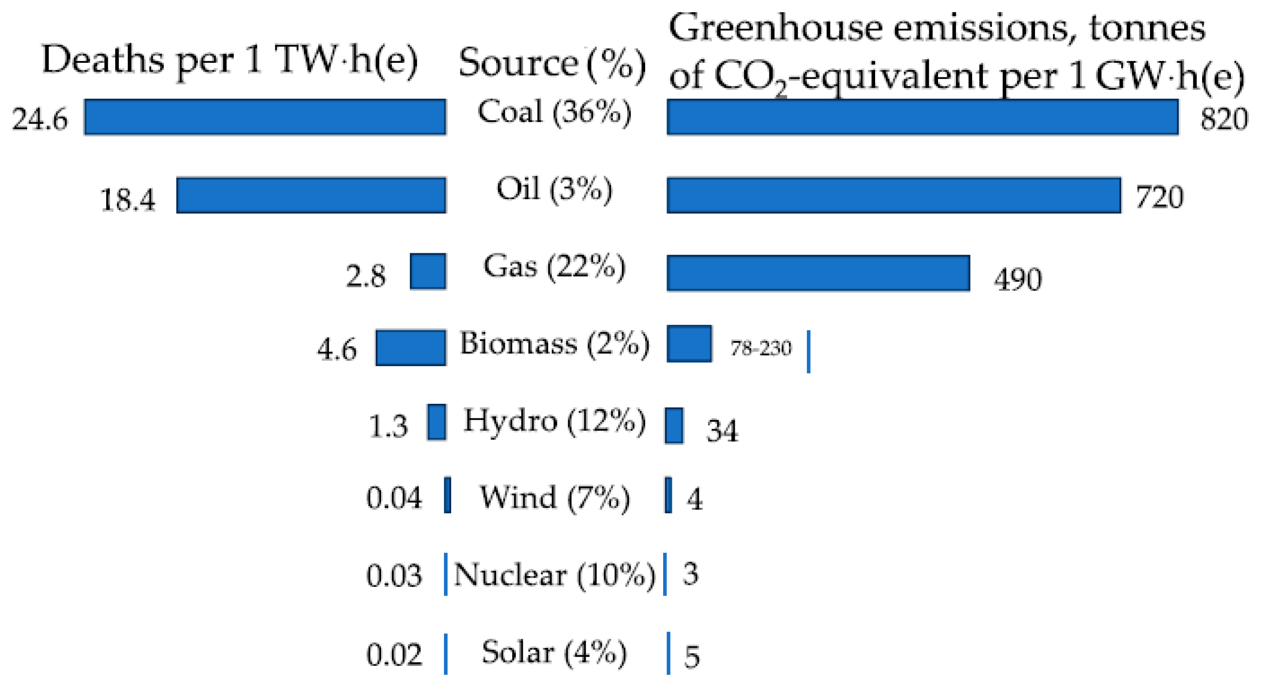
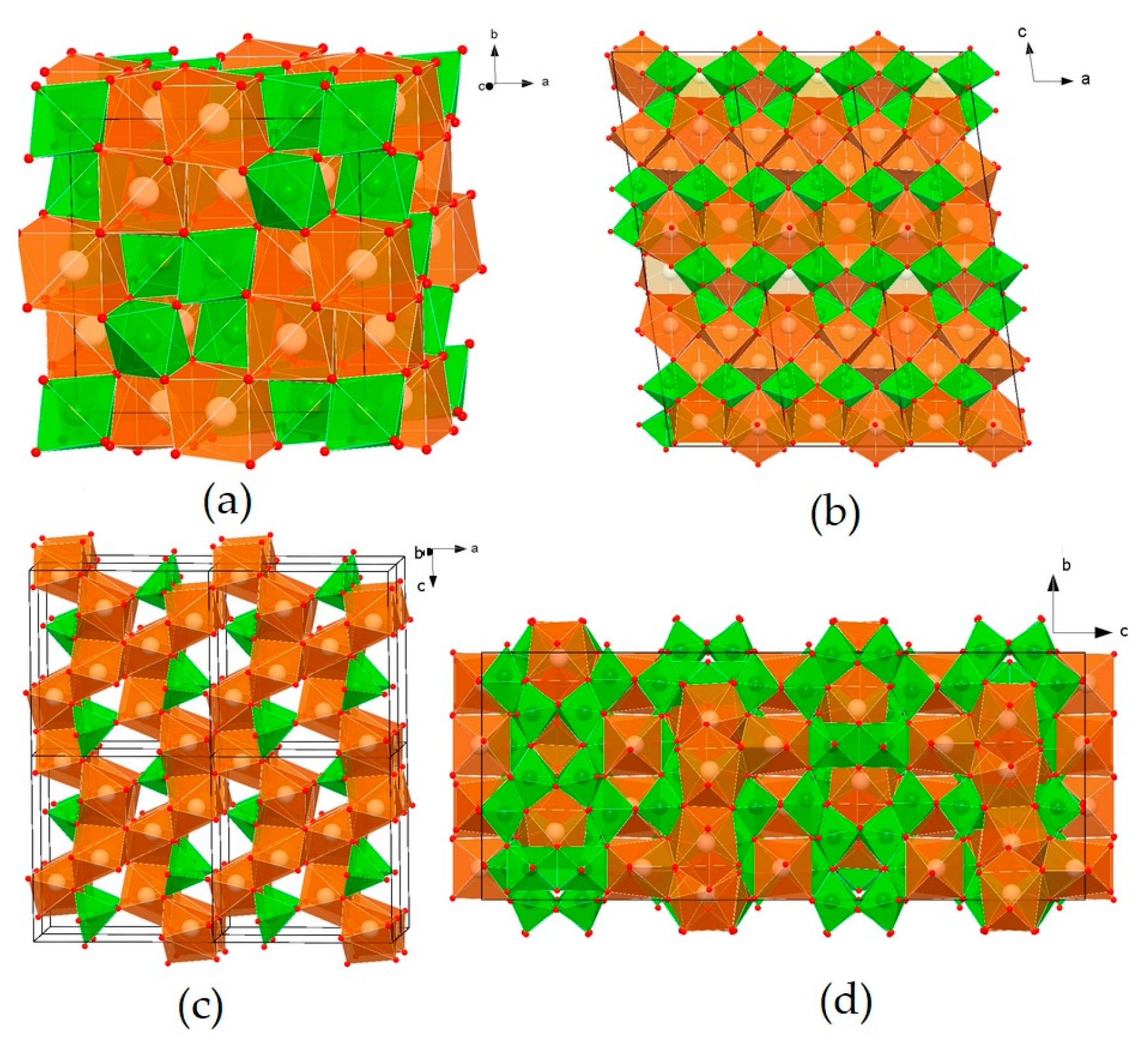
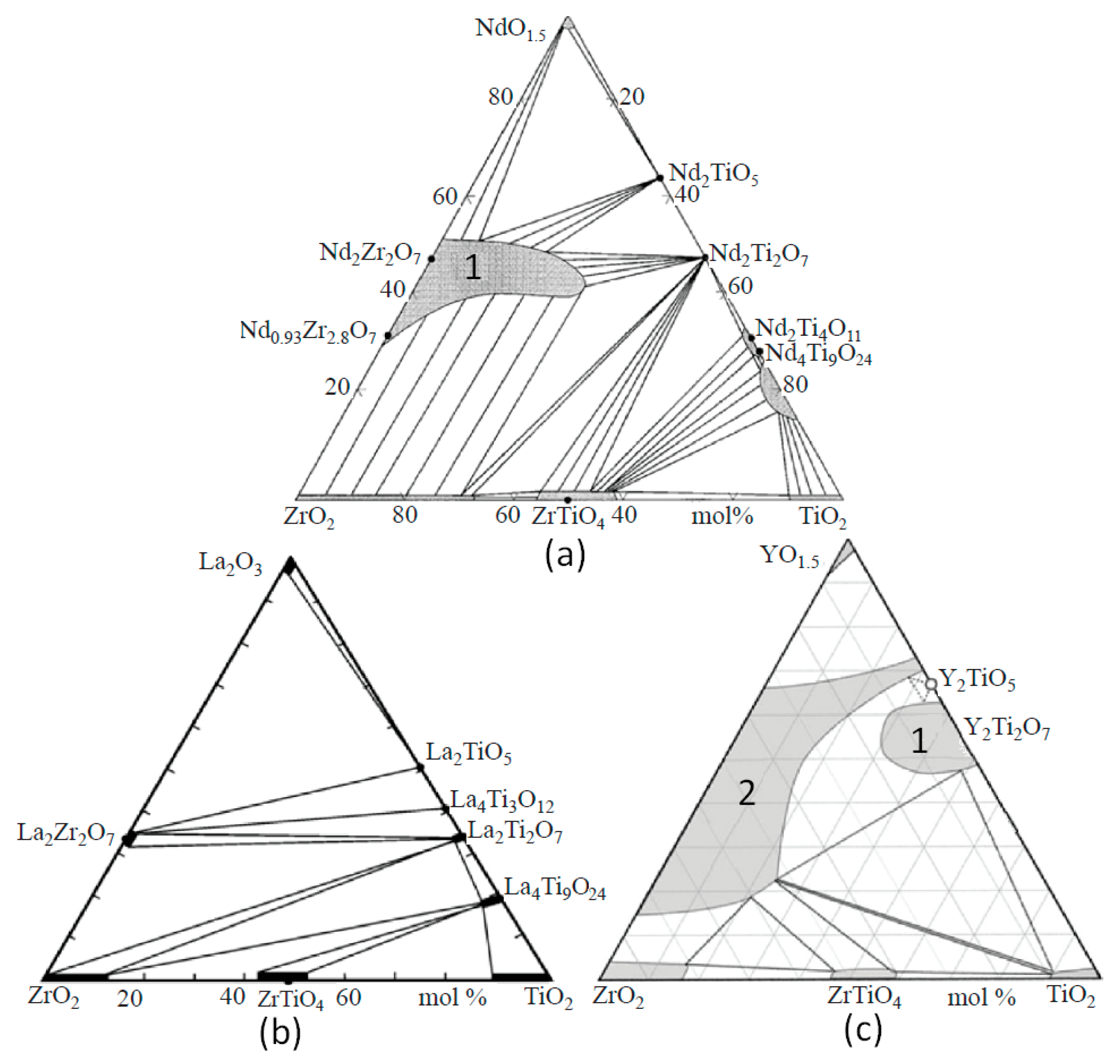
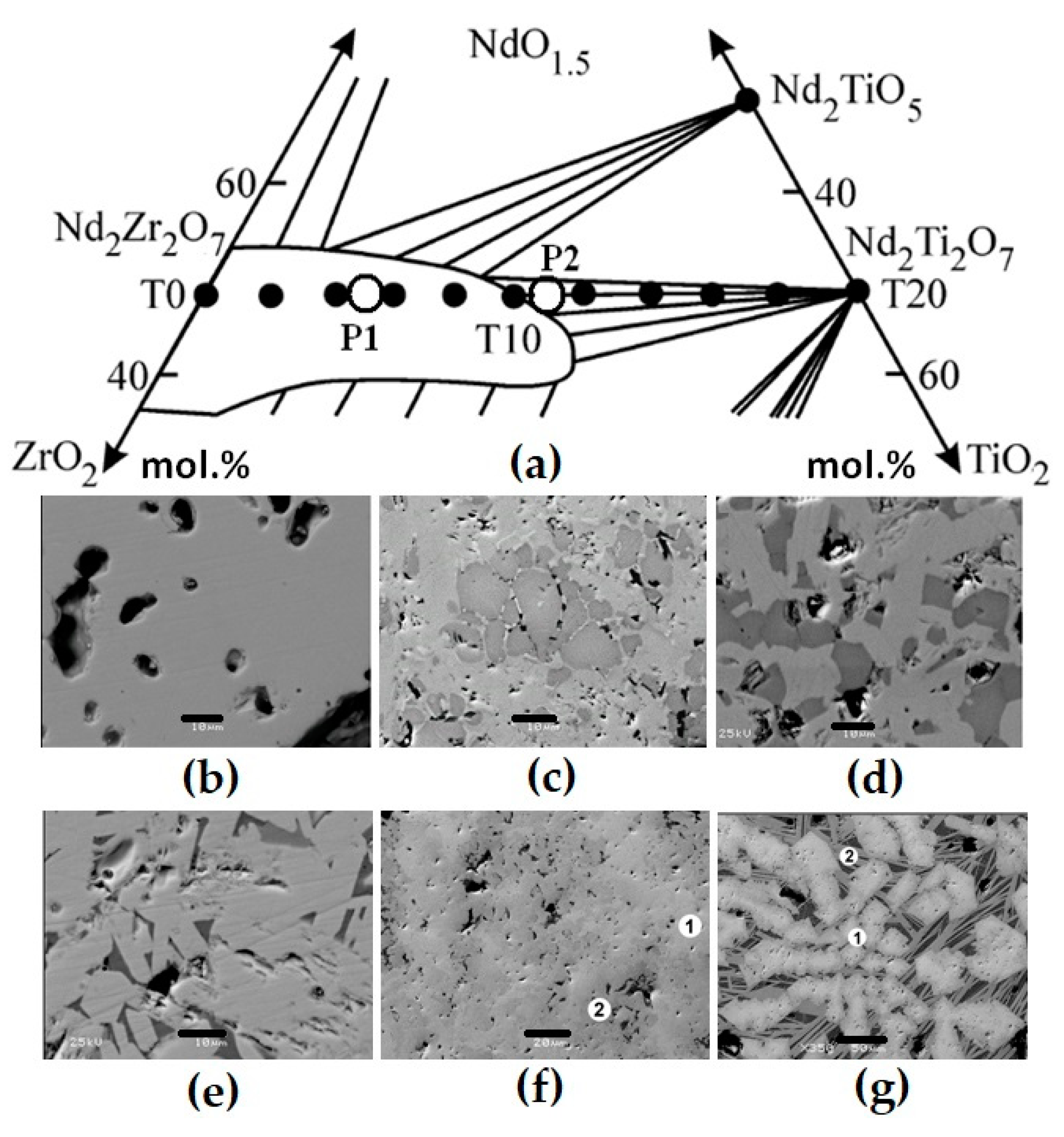

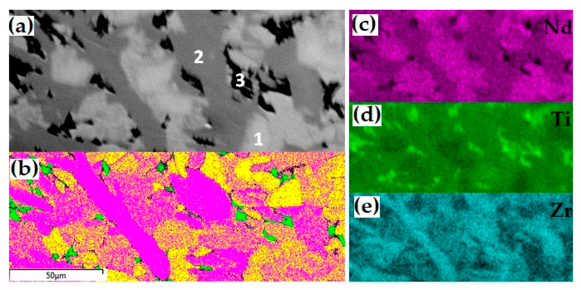
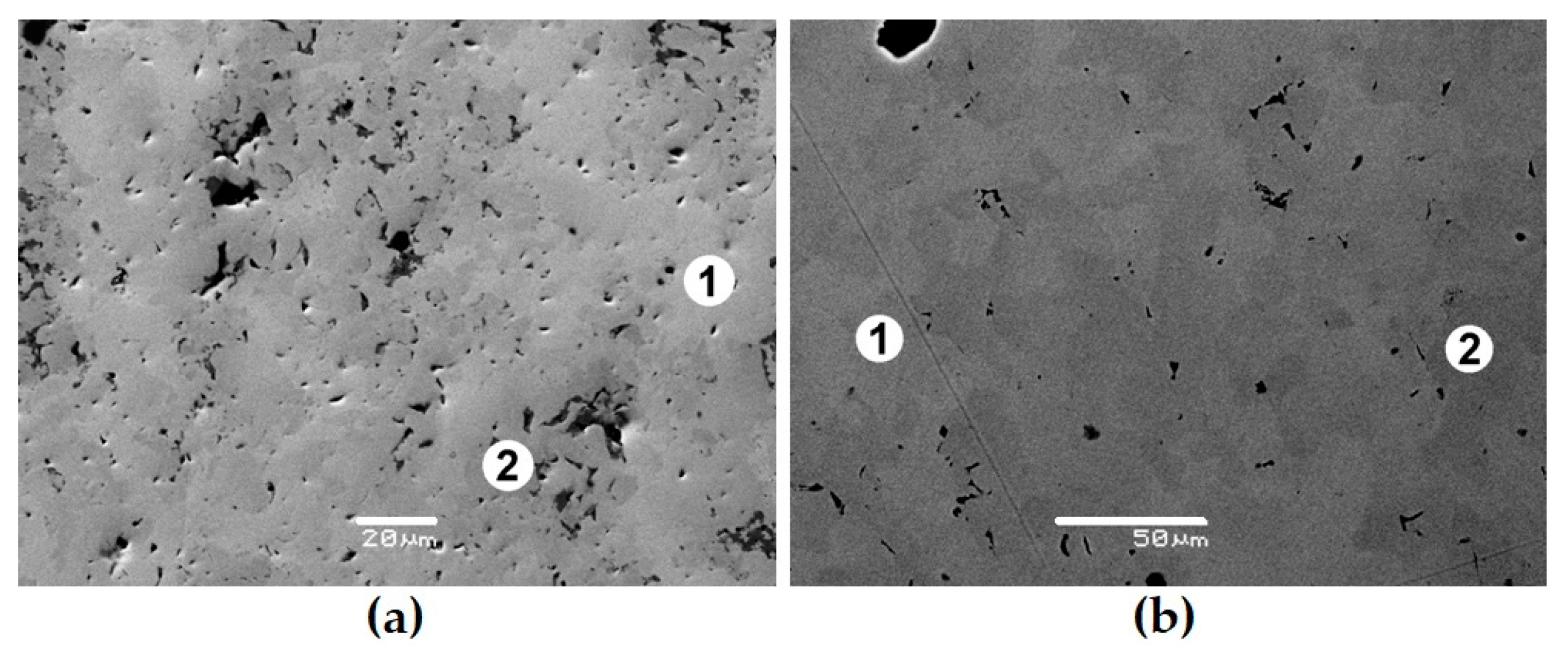
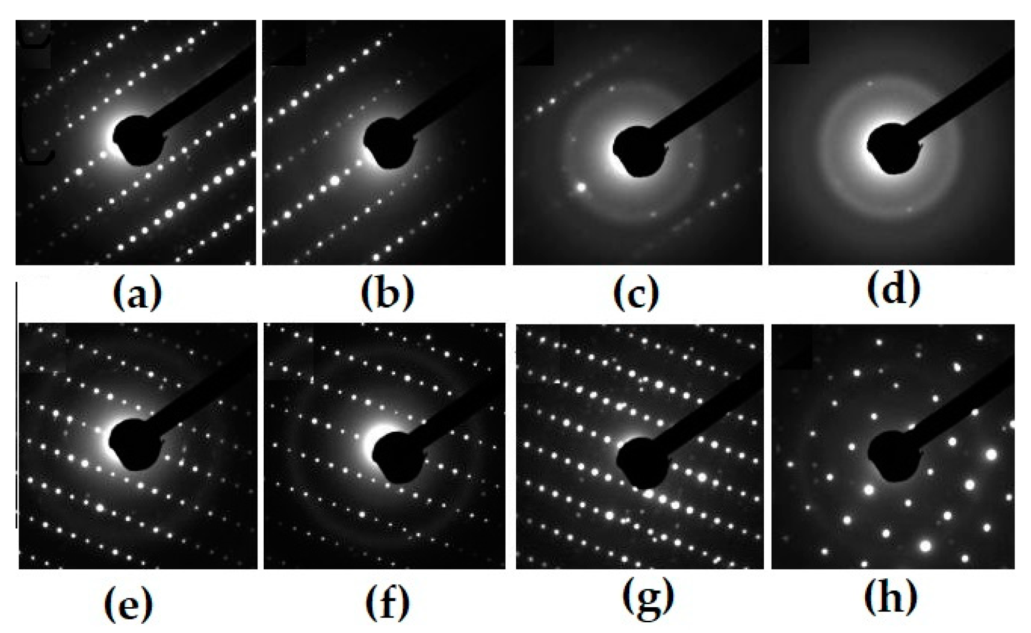
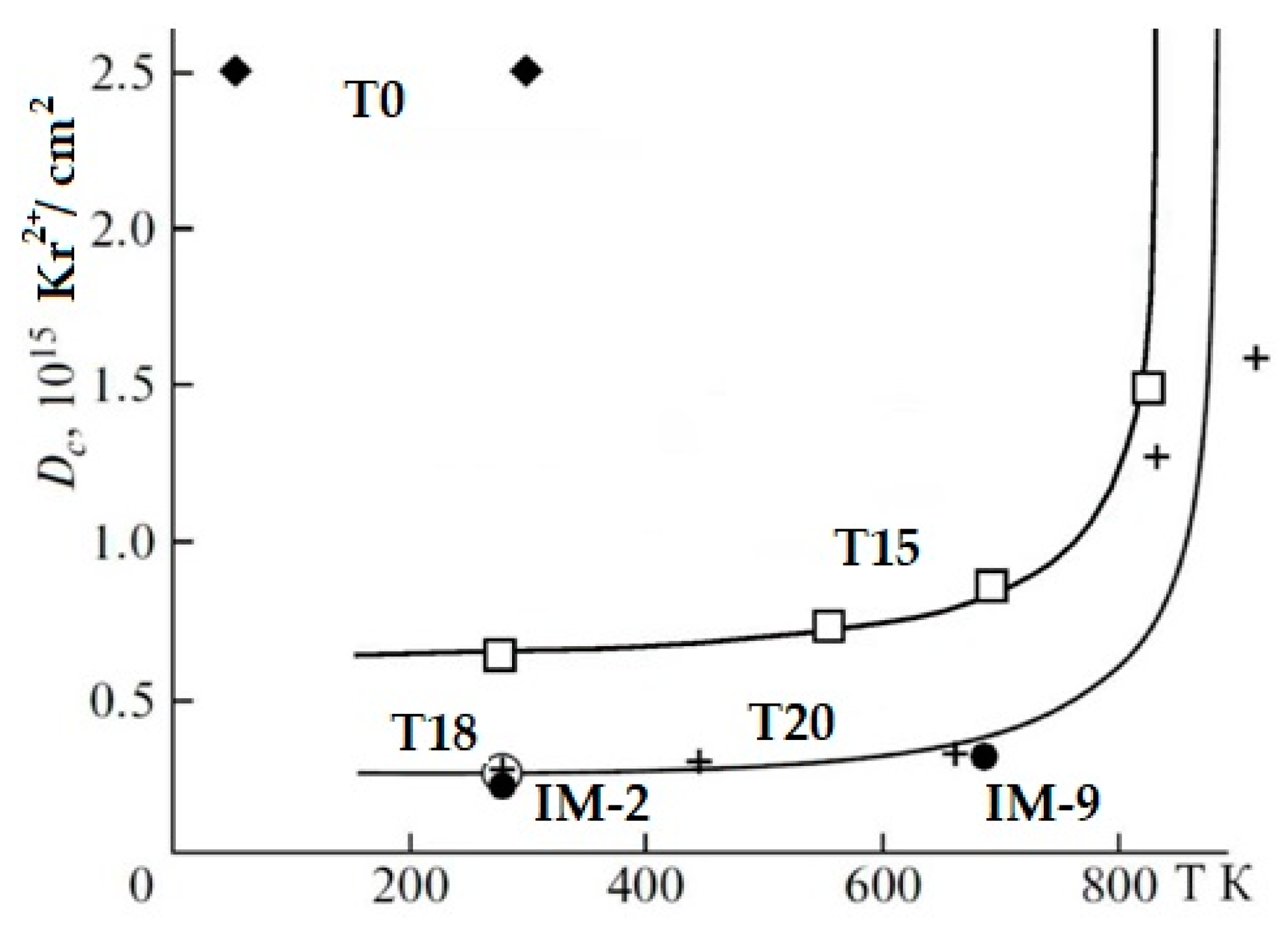
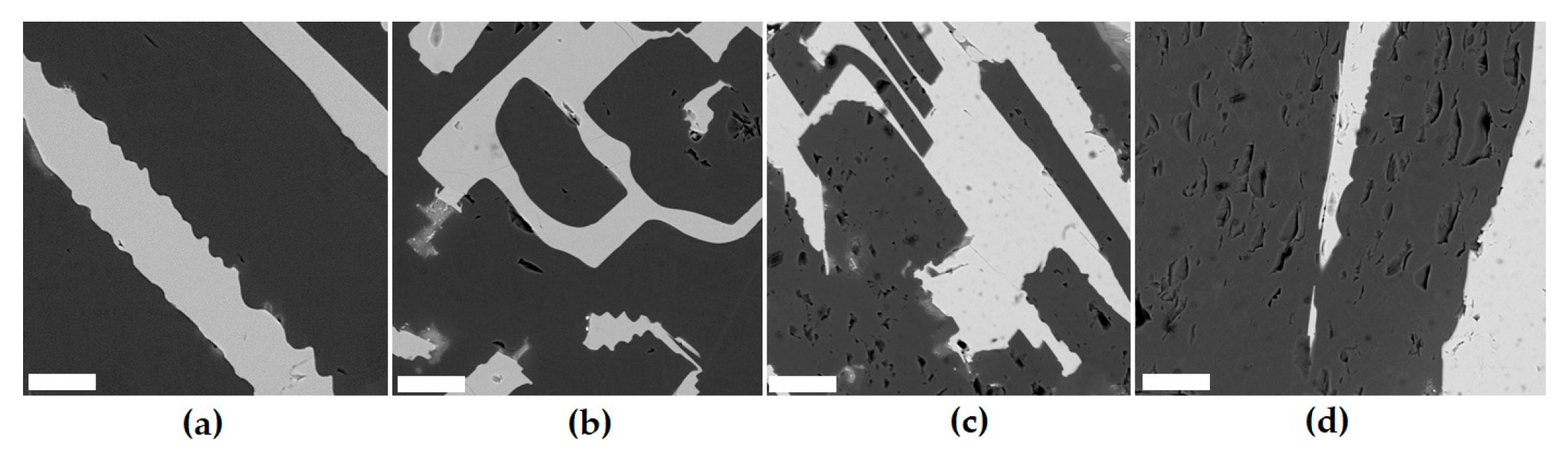

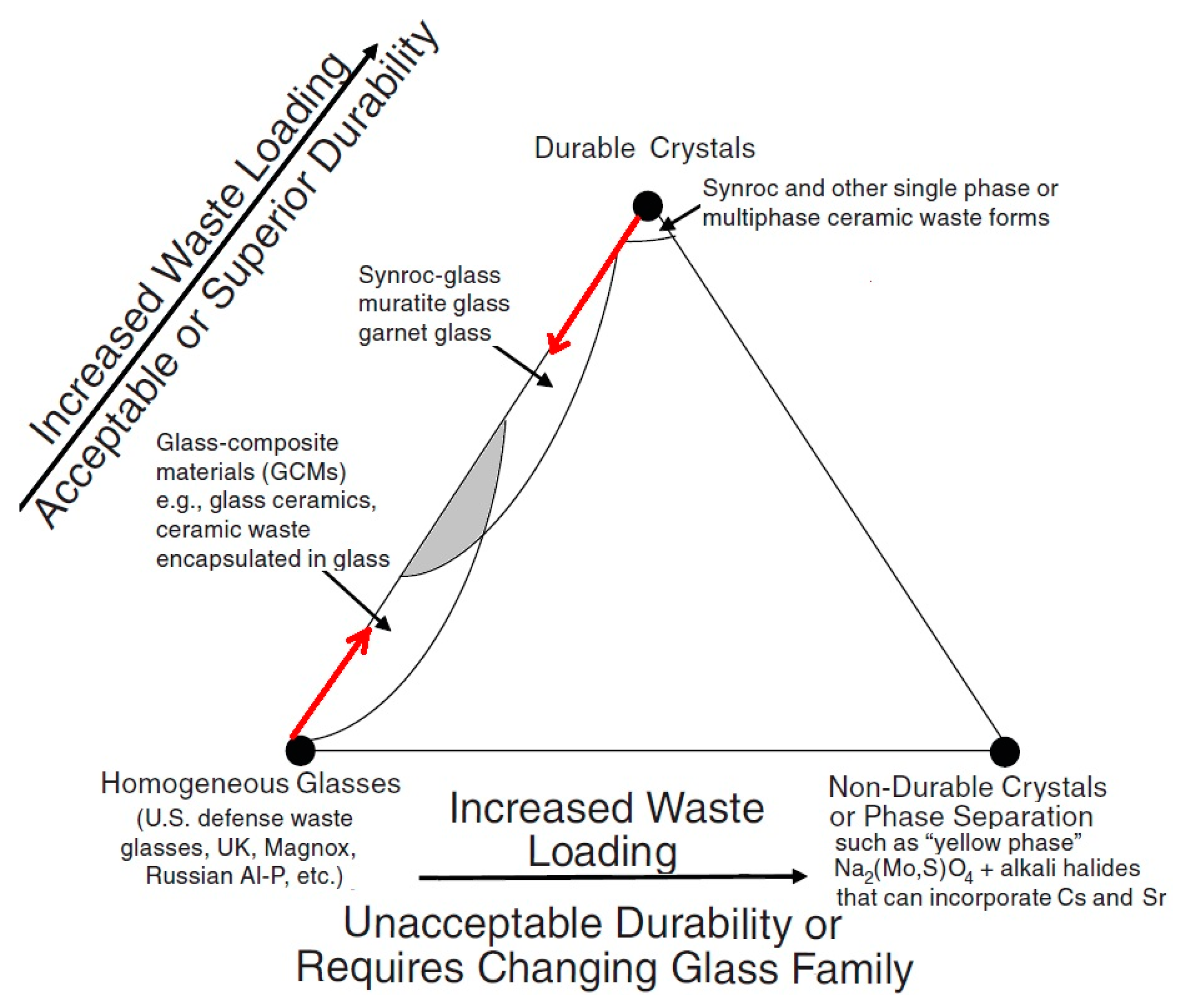
Disclaimer/Publisher’s Note: The statements, opinions and data contained in all publications are solely those of the individual author(s) and contributor(s) and not of MDPI and/or the editor(s). MDPI and/or the editor(s) disclaim responsibility for any injury to people or property resulting from any ideas, methods, instructions or products referred to in the content. |
© 2025 by the authors. Licensee MDPI, Basel, Switzerland. This article is an open access article distributed under the terms and conditions of the Creative Commons Attribution (CC BY) license (https://creativecommons.org/licenses/by/4.0/).