Article

Numerical Analysis and Life Cycle Assessment of Type V Hydrogen Pressure Vessels

by
Mohd Shahneel Saharudin
1,*,
Syafawati Hasbi
1,2,
Santosh Kumar Sahu
3,
Quanjin Ma
4 and
Muhammad Younas
1
1
School of Computing & Engineering Technology, Robert Gordon University, Garthdee Road, Aberdeen AB10 7QB, UK
2
Fakulti Kejuruteraan, Universiti Pertahanan Nasional Malaysia (UPNM), Kem Perdana Sungai Besi, Kuala Lumpur 57000, Malaysia
3
School of Mechanical Engineering, VIT-AP University, Besides A.P Secretariat, Andhra Pradesh, Amaravati 522237, India
4
School of System Design and Intelligent Manufacturing, Southern University of Science Technology, Shenzhen 518055, China
*
Author to whom correspondence should be addressed.
J. Compos. Sci. 2025, 9(2), 75; https://doi.org/10.3390/jcs9020075
Submission received: 29 December 2024 / Revised: 21 January 2025 / Accepted: 5 February 2025 / Published: 7 February 2025
(This article belongs to the Special Issue Theoretical and Computational Investigation on Composite Materials)

Abstract

:
The growing concern about greenhouse gas emissions and global warming has heightened the focus on sustainability across industrial sectors. As a result, hydrogen energy has emerged as a versatile and promising solution for various engineering applications. Among its storage options, Type V composite pressure vessels are particularly attractive because they eliminate the need for a polymer liner during manufacturing, significantly reducing material usage and enhancing their environmental benefit. However, limited research has explored the pressure performance and life cycle assessment of these vessels. To address this gap, this study investigates the pressure performance and carbon emissions of a Type V hydrogen pressure vessel using four composite materials: Kevlar/Epoxy, Basalt/Epoxy, E-Glass/Epoxy, and Carbon T-700/Epoxy. The results reveal that Carbon T-700/Epoxy is the most suitable material for high-pressure hydrogen storage due to its superior mechanical properties, including the highest burst pressure, maximum stress capacity, and minimal deformation under loading. Conversely, the LCA results, supported by insights from a large language model (LLM), show that Basalt/Epoxy provides a more sustainable option, exhibiting notably lower global warming potential (GWP) and acidification potential (AP). These findings highlight the trade-offs between mechanical performance and environmental impact, offering valuable insights for sustainable hydrogen storage design.

1. Introduction

Hydrogen has appeared as an important option in the transition to a more sustainable and environmentally friendly energy [1]. Recognised as a clean and efficient energy carrier, hydrogen presents a promising alternative to conventional fossil fuels. Its versatility and eco-friendly nature allow it to be produced through various methods, including traditional processes and renewable approaches such as solar- or wind-powered electrolysis [2,3,4].
To date, numerous sectors, such as transportation, power generation, and heating, have been observed to benefit from hydrogen [5]. It serves a vital function related to providing a route to decarbonise traditionally challenging areas, and its integration into various industries has gained significant attention as a means of reducing carbon emissions within energy systems. For example, hydrogen is used to power fuel cell electric vehicles (FCEVs) in the transportation industry, which allows extended driving ranges and faster refuelling potentials [6]. These vehicles produce only water vapour as a by-product, offering a zero-emission alternative to conventional internal combustion engine vehicles. Additionally, hydrogen also could be used in power generation through combustion in gas turbines or electricity production via fuel cells.
Although hydrogen energy has received positive feedback, it is not without challenges, including high production costs, as well as difficulties in storage and transportation [7]. Its low density and high flammability necessitate robust safety protocols and efficient handling practices to ensure secure and effective utilisation [8,9]. Additionally, hydrogen storage poses a considerable hurdle due to its inherent volatility and the complexities associated with compressing the gas [10,11].
Hydrogen has a lower volumetric energy density (9.9 MJ/m3) compared to fossil fuels, thus, generally, large storage systems that are safe, efficient, and cost-effective are needed. In automotive applications [12], hydrogen tanks must follow certain standards; these include a 15-year service life and the ability to endure pressures 1.25 to 2.25 times the designated working pressure for commercial heavy-duty vehicles, in compliance with ISO 15869 [13,14]. Subsequently, effective hydrogen storage requires either high-pressure systems, low-temperature environments, or materials capable of securely binding hydrogen molecules.
Manufacturing and experimenting with hydrogen storage vessels to investigate the effects of shape variations on performance are costly and time consuming. Thus, Finite Element Analysis (FEA) is often used for predicting burst pressure and failure characteristics [15]. This approach is not only efficient but also very economical. This method allows for the development of digital designs prior to the real manufacturing and testing [16]. The feasibility and reliability of the proposed models can be carried out at minimal cost [17,18,19].
Since composites are heterogeneous [20] and anisotropic, there is need to tailor the modelling strategies to enable accurate simulation of their behaviour and performance under various conditions [21]. Shaktivell et al., in their research, reported the effect of composite lay-up, which was investigated effectively using FEA [22]. Various orientations were simulated and analysed throughout this research.
As mentioned earlier, FEA models for composites consider properties such as anisotropic mechanical behaviour and intricate failure mechanisms. Commonly used elements in composite FEA include solid, shell, plate, and cohesive elements, each designed to address specific aspects of composite performance. Advanced software tools like Ansys 2025, Abaqus 2025, and, recently, SolidWorks 2025, integrate specialised functions to manage the complexities of composite stress analysis. These three software packages are capable of simulating fibre weaving patterns and microscale simulations [23,24]. These developments facilitate the effective and accurate design, analysis, and optimisation of composite materials, thus offering valuable understandings into hydrogen pressure vessel characteristics. The development of Type IV hydrogen pressure vessels has made them a preferred choice for storing, transporting, and utilising hydrogen as an energy source. However, the popularity of Type V hydrogen pressure vessels has been increasing recently, as they do not require a polymer liner. According to Ma et al., type V offers the best pressure vessel efficiency compared to the other four types [25]. Besides that, waste is also significantly reduced, while a high performance is maintained. The manufacturing of Type V hydrogen pressure vessels also contributes to lower development costs and operational risks [26,27,28].
Although hydrogen technology is rapidly advancing with various compelling research outcomes, further efforts are necessary to evaluate the environmental impacts of these technologies, particularly concerning Type V hydrogen pressure vessels. In this preliminary study, the 700-bar storage tank is identified as suitable for various applications, including emergency portable fuel cell systems and backup power for data centres, hospitals, and remote facilities [29]. Most notably, this storage tank can also be utilised in Fuel Cell Electric Vehicles (FCEVs), provided its size is appropriately adjusted to meet vehicle requirements [30,31].
Life cycle assessment (LCA) can be applied to evaluate the environmental impacts of any activity involving the consumption of goods and services [32]. Nowadays, life cycle analysis practitioners could easily integrate large language models (LLMs) into their environmental impact analysis. This emergent technique could offer some benefits because of the capability of these models to process and generate text efficiently [33]. Consequently, this approach can decrease the time to complete LCA studies; at the same time, it is easy to use. LLMs allow better life cycle inventory data collection and interpretation of the life cycle impact assessment. Nevertheless, this approach can be used efficiently by the LCA practitioner through accurate prompt engineering techniques [34]. Additionally, appropriate steps need to be taken into consideration to effectively use LLMs for LCA. The opportunities presented by integrating the generative AI models can streamline the LCA process and result in significant benefits for the LCA practitioner [35].
In this research, four composite materials with superior mechanical properties were selected and compared based on their burst pressure performance and life cycle assessment. The materials—Kevlar, Basalt, E-Glass, and Carbon—were chosen due to their comparable mechanical properties and popularity for applications requiring a high strength-to-weight ratio [36], excellent corrosion resistance [37], and the ability to minimise hydrogen leakage, a critical safety factor for pressure vessels [38,39].

2. Materials and Methods

This research utilised the specified geometry based on the comprehensive dimensions provided by previous researchers [40]. The 2D drawing in Figure 1 was initially created as a 3D model in SolidWorks 2025, Dassault Systèmes, Massachusetts, USA and subsequently converted into a 2D representation, as illustrated below. The liner features an outer diameter of 60 mm, an inner diameter of 56 mm, a length of 124 mm between the domes, and a wall thickness of 2 mm. Notably, this liner was fabricated as part of the manufacturing process for a Type IV pressure vessel. Subsequently, it was wrapped with glass fibre using the filament winding technique. The ABS liner was selected due to its ease of manufacturing using Fused Deposition Modelling (FDM). The ABS material offers excellent mechanical properties suitable for the intended application in composite overwrapped pressure vessels, as corroborated by previous research [41]. Figure 2 presents the isometric view of the ABS liner geometry utilised in this study as a baseline.

2.1. Mesh Dependency Study

Mesh dependency studies were conducted to determine the optimal mesh size. Five mesh sizes, ranging from 1 mm to 5 mm, were evaluated, as shown in Figure 2. A mesh with 50,227 elements was selected for this study, as it demonstrated only a 0.4% variation compared to the results of a finer mesh.

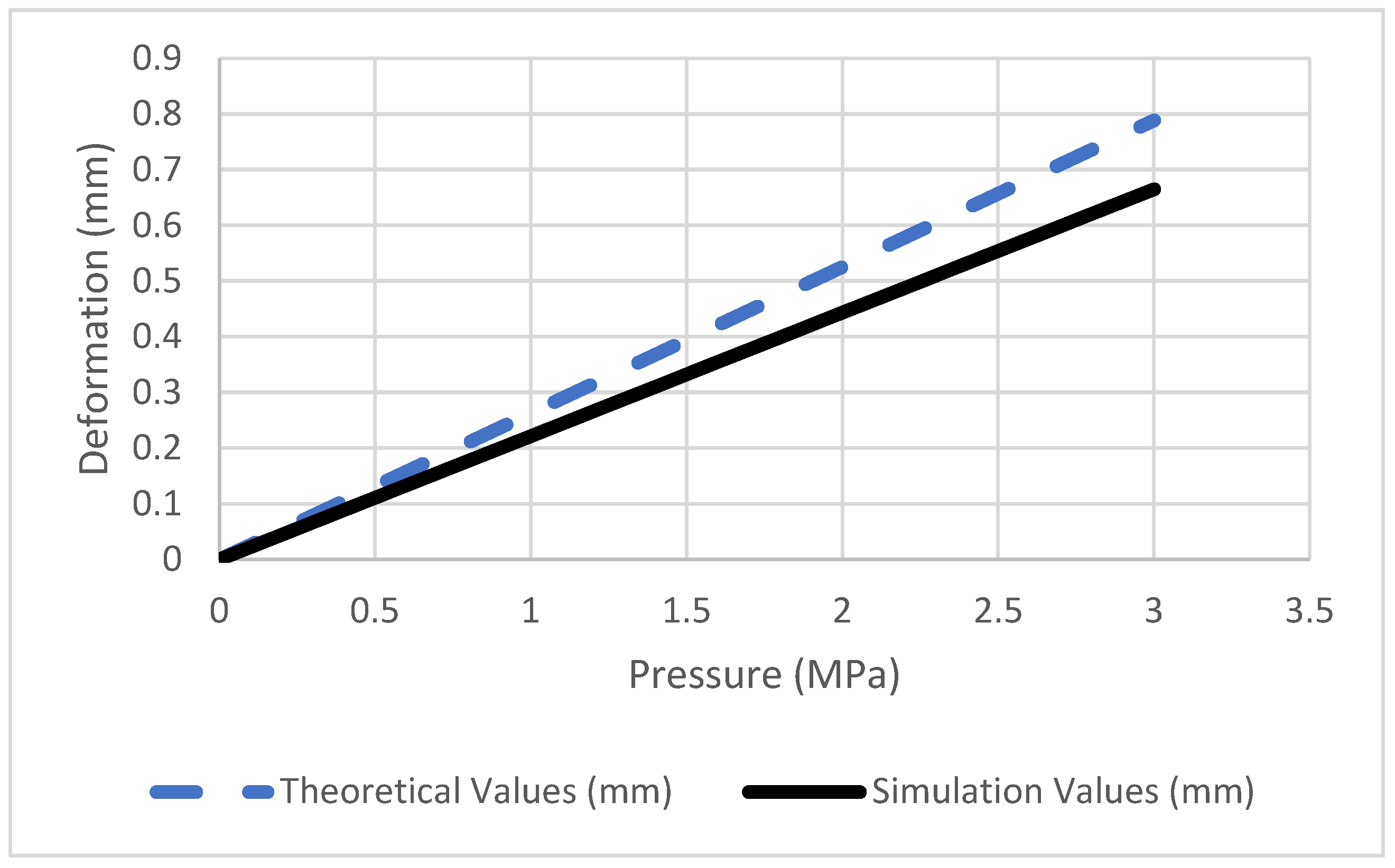
2.2. Validation of the Simulation

After completing the 3D modelling in SolidWorks, the geometry was exported as a STEP file for use in ANSYS structural analysis. Figure 3 illustrates the boundary conditions applied during the structural analysis. The model was simulated under the following conditions, which include two fixed supports (indicated in blue) and variable pressure ranging from 0.2 MPa bar to 1 MPa (indicated in red). An optimised mesh size of 3 mm was employed, which proved effective for the structural analysis. The mechanical properties of the ABS liner are detailed in Table 1. In this study, the simulation results were compared with analytical calculations derived from the governing equation provided in Equation (1). Normal pressure was applied to the vessel in the range from 0.2 MPa to 1 MPa, as stated above, which was selected to align with the working pressure range of the ABS liner.
The simulation results indicate a maximum deformation of 0.66495 mm, which is reasonably close to the calculated analytical value of 0.7884375 mm (Table 2). The percentage discrepancy is 15.66%, which is moderate and within the acceptable range [42]. While the simulation results are consistently lower than the theoretical values, the differences remain small, as illustrated in Figure 4.

2.3. Governing Equation

For a thin-walled pressure vessel, the radial deformation (ur) is calculated using the formula [43,44]:
    u r = P · r 2 E · t
where:
  • P is applied internal pressure (MPa);
  • r is mean radius of the vessel, r = (Douter + Dinner)/4 (mm);
  • E is Young’s modulus of the material (MPa);
  • t is wall thickness, t = (Douter − Dinner)/2 (mm).

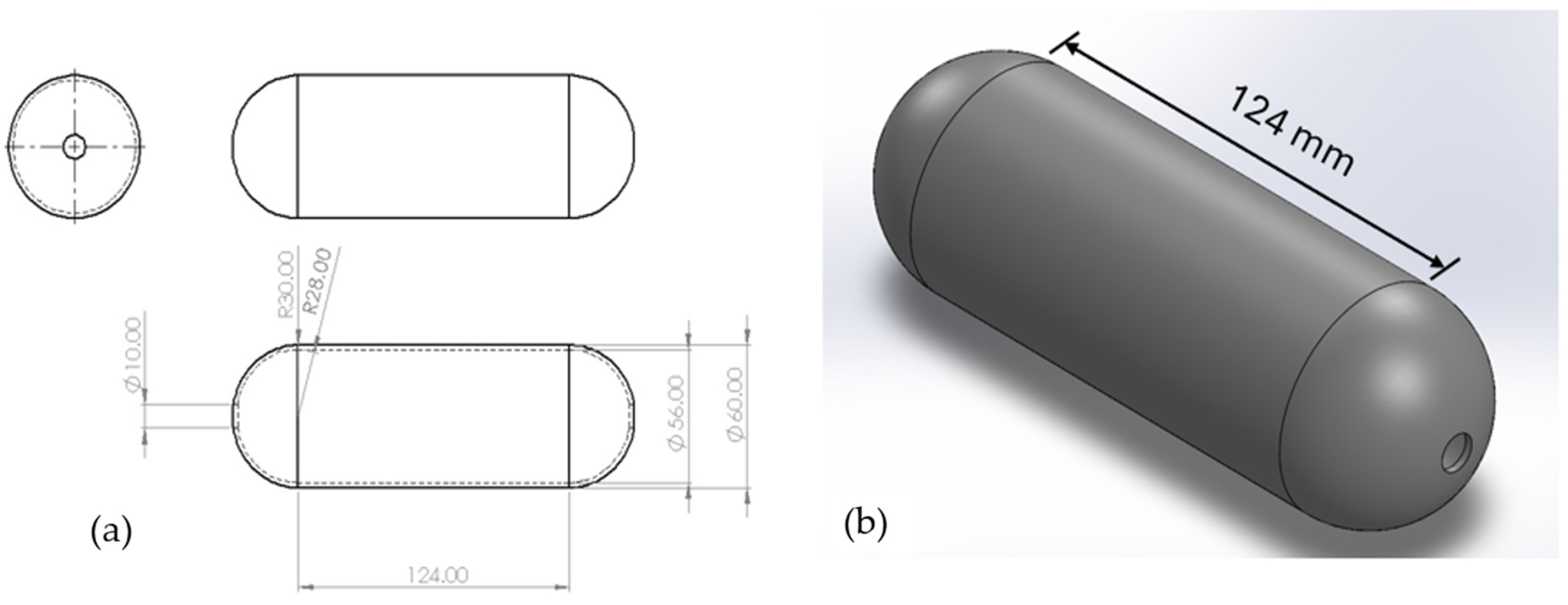
2.4. Input Parameters

The following parameters were used in the simulation validation of ABS polymer liner:
  • Outer Diameter (Douter): 60 mm
  • Inner Diameter (Dinner): 56 mm
  • Wall Thickness (t): 2 mm
  • Mean Radius (r): 29 mm
  • Young’s Modulus (E): 1600 MPa
  • Applied Pressures (p): [0, 1, 1.2, 1.4, 3.0] MPa
The formula is applied to all pressures to compute the deformations.
Figure 5 presents a top view of the hydrogen pressure vessel (without a wireframe) simulated in this study. Figure 6 displays a sectional plane of the Carbon T-700/Epoxy hydrogen pressure vessel. The image clearly shows four layers of composite materials stacked together. It is evident that no liner is present, as the Type V pressure vessel is constructed entirely from composite materials. This design significantly reduces the overall weight of the vessel.
Figure 7 shows the stacking sequence of the composite laminates consistently applied to all four materials (Kevlar/Epoxy, Basalt/Epoxy, E-Glass, and Carbon T-700/Epoxy). In this study, the geometry used was in the form of a “surface” element, and 4 mm thickness of laminates were stacked on it. There are two main reasons why such an orientation was chosen. Sapre, in their study, reported that the 0° layers provide high strength and stiffness in the longitudinal direction, making the composite capable of withstanding tensile or compressive loads along the primary axis [15]. As for the 90° layers, it enhances strength and stiffness in the transverse direction [45], resulting in the avoidance of damage like transverse cracking or delamination. The Ansys Composite PrepPost (ACP) was used in preparing the composite, which is an integrated tool in the Workbench platform dedicated to composite laminate modelling. The properties of the materials are presented in Table 3.
Burst Pressure [14]
P = σ t · t r i    
where P is the burst pressure (Pa),   σ t the tensile strength in the hoop (X-direction for orthotropic materials) (Pa), t the wall thickness, and r i the inner radius.

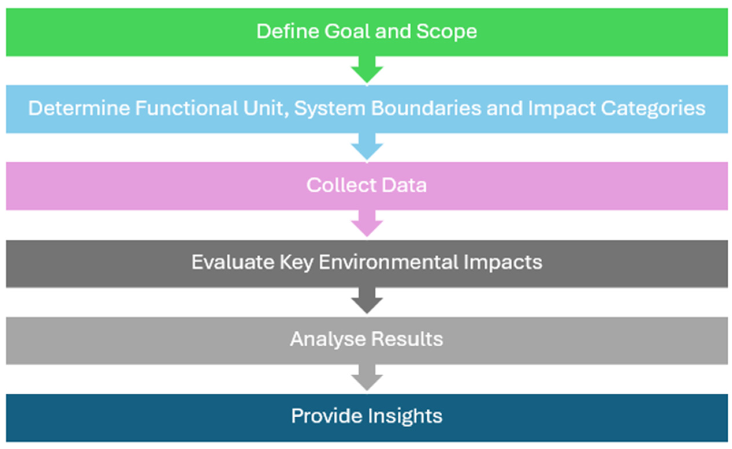
3. Life Cycle Assessment

The life cycle assessment (LCA) of hydrogen pressure vessels was conducted in compliance with the ISO 14,040 and ISO 14044 standards [47], encompassing the phases of Goal and Scope Definition, Life Cycle Inventory (LCI), Life Cycle Impact Assessment (LCIA), and Interpretation. In this study, the functional unit was defined as storing 11.93 g of hydrogen at 700 bar, with the assessment limited to cradle-to-use boundaries excluding end-of-life (EOL) scenarios. The LCA was carried out using a new technique named the large language model (LLM). This model has emerged as a revolutionary artificial intelligence system that can process and produce text with reasonable communication and simplify numerous tasks [48]. This new technique offers few advantages due to the capacity of these models to generate and process text quickly and efficiently [49]. Therefore, this technique significantly decreases the time required to carry out an LCA and increases the ease of use of LCAs.
The objective was to evaluate and compare the environmental impacts of four composite materials (Carbon T-700/Epoxy, Kevlar/Epoxy, E-Glass Fiber/Epoxy, and Basalt/Epoxy) when used as materials to fabricate type V hydrogen pressure vessels. Data collection focused on material inputs (e.g., fibres, epoxy resin, aluminium alloy), energy requirements (UK electricity grid mix), and transportation emissions (diesel trucks). Secondary data from the literature and databases supplemented material production emissions. Life Cycle Impact Assessment (LCIA): The following categories were assessed:
  • Global Warming Potential (GWP) (kg CO2-eq): Quantifying greenhouse gas emissions.
  • Acidification Potential (AP) (kg SO2-eq): Assessing impacts from SO2 and NOₓ emissions.
  • Photochemical Ozone Creation Potential (POCP) (kg C2H4-eq): Evaluating VOC and NOₓ contributions to ground-level ozone formation.
  • Particulate Matter Formation (PMF) (kg PM10): Quantifying PM emissions from transportation and energy use.
Figure 8 shows the flow chart of the large language model (LLM) used to evaluate the environmental impact analysis in this study. This flow chart outlines the process for evaluating environmental impact analysis using a systematic approach. The process begins by defining the goal and scope, establishing the objectives and boundaries of the study. Next, the functional unit, system boundaries, and impact categories are determined, providing a clear basis for comparison and analysis. These steps ensure a structured framework for the evaluation.
Following this, data collection is performed to gather all necessary information, forming the foundation for the analysis. The collected data are then utilised to evaluate key environmental impacts, identifying areas of significant influence. The results are subsequently analysed to draw meaningful conclusions. Finally, the process concludes with the provision of insights, offering actionable recommendations or findings based on the analysis. This structured approach ensures a comprehensive and methodical evaluation of the environmental impacts.

4. Results

Table 4 presents the burst pressure results, it is evident that the hydrogen pressure vessel made with Carbon-T700/Epoxy exhibits the highest burst pressure, followed by those made with Kevlar, Basalt, and E-Glass fibre materials. Considering the allowable working pressure with a safety factor of 2.25, the corresponding values are provided in the table. Similarly, in Figure 9, the bar chart better shows the comparison between the burst pressure and allowable working pressure.
Based on Figure 10, the relationships between maximum principal stress (MPa) and pressure (bar) for different composite materials are presented. The graph suggests that the hydrogen pressure vessel using Carbon T-700/Epoxy shows the highest principal stress among the other materials at the pressures applied. This linear stress response implies a high strength and reliable performance under increasing pressure. The second highest maximum principal stress is Basalt/Epoxy. It demonstrates good-load bearing capacity even though lower than Carbon T-700. E-Glass fibre and Kevlar present intermediate and lower stress capacities. This further prove it is the most suitable material for high-pressure applications, followed by Basalt/Epoxy. Kevlar/Epoxy and E-Glass Fibre/Epoxy show lower stress capacities. Both materials, however, were better suited for moderate or low-pressure applications. Figure 11 shows the maximum equivalent stress against pressure for different materials. A similar trend can be observed, where Carbon T-700/Epoxy had the highest equivalent stress at 211 MPa, followed by Kevlar/Epoxy at 116 MPa. This further indicates that carbon can withstand significantly higher stress [50] compared to the other materials. Besides that, Carbon T-700/Epoxy is known for its superior strength and stiffness. This can be associated with its high modulus of elasticity and load-bearing capability, resulting in higher stress values. Basalt/Epoxy had a value of 106.5 MPa, and the lowest value was observed for E-Glass Fiber/Epoxy at 95 MPa. In general, Basalt and E-Glass fibres have less efficient load transfer and higher deformation, leading to reduced stress values. Additionally, although Basalt/Epoxy is relatively inexpensive, it possesses lower mechanical properties compared to the other materials. The simulated material behaviour aligns with their intrinsic properties, demonstrating that Carbon T-700/Epoxy is optimised for high-performance applications, whereas the other materials reflect trade-offs between cost, strength, and flexibility. Figure 12 shows the equivalent elastic strain of the composites under varying loads. Carbon T-700/Epoxy has the highest Young’s modulus, which results in lower deformation under applied pressure. This makes it ideal for applications requiring minimal strain, including pressure vessels. Kevlar/Epoxy, on the other hand, has relatively lower stiffness, which explains its higher strain values under pressure. The graph in Figure 13 illustrates the relationship between maximum principal elastic strain and pressure for four composite materials, highlighting their deformation behaviour under load. Carbon T-700/Epoxy exhibits the lowest strain due to its high stiffness, making it ideal for high-pressure applications, while Kevlar/Epoxy shows the highest strain, consistent with its energy-absorbing and flexible nature.
Table 5 provides the fibre and epoxy weights required to manufacture one unit of a pressure vessel for the four different composite materials. While all materials use the same amount of epoxy (56.7 g), the fibre weight varies, with Basalt/Epoxy requiring the highest fibre weight (129.64 g) and Kevlar/Epoxy the lowest (97.76 g), reflecting differences in material density and composition. The Table 6 summarises the components, materials, and their respective weights used to manufacture a single pressure vessel. The fibre (111.23 g) and polymer matrix (56.7 g) form the composite structure, while additional components like the boss (192 g) made of aluminium alloy, polyethylene coating (33 g), and small seals and gaskets made of NBR (1.7 g and 0.97 g respectively) complete the assembly for structural integrity and functionality. Figure 14 compares the global warming potential (GWP) for pressure vessels made from different materials, highlighting contributions from fibre production, epoxy, aluminium boss, polyethylene coating, manufacturing, and transportation. Carbon T-700/Epoxy has the highest total GWP due to energy-intensive fibre production, while Basalt/Epoxy has the lowest, making it a more sustainable option for applications prioritising environmental impact. Figure 15 compares the acidification potential (AP), measured in kg SO2-equivalent, for the pressure vessels manufactured from four materials, Carbon T-700/Epoxy, Kevlar/Epoxy, E-Glass Fiber/Epoxy, and Basalt/Epoxy, based on contributions from fibre production, epoxy production, and transportation. Carbon T-700/Epoxy has the highest acidification potential due to the energy-intensive process of carbon fibre production, while the other materials, particularly Basalt/Epoxy, exhibit lower acidification potential, making them more environmentally sustainable in terms of acid-rain-causing emissions. Figure 16 illustrates the photochemical ozone creation potential (POCP), measured in kg C2H4-equivalent, for pressure vessels made from four materials: Carbon T-700/Epoxy, Kevlar/Epoxy, E-Glass Fiber/Epoxy, and Basalt/Epoxy. The total POCP is primarily driven by epoxy production, with consistent contributions across all materials, while transportation POCP has a negligible impact. The similar total POCP values for all materials indicate that the environmental impact in terms of photochemical smog formation is largely determined by the resin rather than the choice of fibre. Figure 17 illustrates the particulate matter formation (PMF), measured in kg PM10-equivalent, for pressure vessels made from four materials: Carbon T-700/Epoxy, Kevlar/Epoxy, E-Glass Fibre/Epoxy, and Basalt/Epoxy. The electricity PMF is the largest contributor to total PMF for all materials, while the transportation PMF remains relatively minor. The total PMF values are consistent across all materials, suggesting that the particulate matter emissions are more influenced by electricity usage during manufacturing than by the type of fibre or material used.

5. End-of-Life Scenarios

In this section, the analysis of end-of-life scenarios for the materials used in the hydrogen pressure vessels is presented. It is worth mentioning the meaningful environmentally friendly advantages of recycling compared to incineration and landfilling. This study found that carbon fibre recycling has about a 50% recovery rate. This provides the highest CO2 savings, reducing emissions by approximately 20 kg CO2 per kilogram of material recycled. For Carbon T-700, this translates to overall savings of ~2.22 kg CO2. Aluminium recycling also offers notable benefits, achieving a 90% recovery rate and saving approximately 9 kg CO2 per kilogram. Kevlar, E-Glass, and Basalt show CO2 savings of ~1.02 kg, ~0.65 kg, and ~0.70 kg, respectively, through recycling efforts.
Conversely, incineration and landfilling contribute more significantly to environmental impacts. Epoxy incineration generates 1.8 kg CO2 per kilogram, though it partially offsets this by recovering 0.4 kg of CO2-equivalent energy. Landfilling NBR (Nitrile Butadiene Rubber) has minimal methane emissions (~0.02 kg CH4 per kilogram), but recycling would further enhance its sustainability. These results emphasise the importance of integrating effective recycling strategies into the life cycle management of hydrogen pressure vessels to reduce their environmental footprint.

6. Discussion

The study demonstrates that Carbon T-700/Epoxy is the most suitable material for high-pressure hydrogen vessels due to its superior mechanical properties, including the highest burst pressure (140 MPa) and maximum stress capacity under applied loads. These advantages are attributed to its high stiffness and modulus of elasticity, ensuring minimal deformation and excellent load-bearing performance. Basalt/Epoxy, while exhibiting lower burst pressure and stress capacities, offers a cost-effective and environmentally sustainable option with the lowest global warming potential (GWP) and acidification potential (AP). Kevlar/Epoxy and E-Glass Fibre/Epoxy show intermediate to low mechanical performance, making them more appropriate for moderate- or low-pressure applications.
The environmental impact assessment revealed that Carbon T-700/Epoxy has the highest GWP, AP, and particulate matter formation (PMF) due to energy-intensive fibre production, while epoxy production contributes consistently to the environmental impact across all materials. Transportation and other components have relatively minor impacts. Basalt/Epoxy stands out as the most sustainable material, with lower emissions across all impact categories. Overall, the trade-offs between performance, cost, and environmental impact highlight Carbon T-700/Epoxy for high-performance applications and Basalt/Epoxy for sustainable, cost-conscious designs. It is important to note that comparing the LCA results with those from previous studies is challenging, particularly for Type V pressure vessels, as similar model studies are not currently available in the literature. Additionally, the materials and weights used in previous studies also differ from those used in the current study. Despite the challenges we have encountered, we firmly believe that life cycle assessments (LCAs) are essential for steering the hydrogen economy toward a low-carbon future. By addressing these challenges, LCAs highlight hydrogen’s potential as a versatile energy carrier, offering significant promise for sustainable energy solutions.

7. Conclusions

Carbon T-700/Epoxy is the most suitable material for high-pressure hydrogen pressure vessels due to its superior mechanical performance, including the highest burst pressure, maximum stress capacity, and minimal deformation under load. However, its production has the highest environmental impact. Basalt/Epoxy, while mechanically inferior, offers more sustainability, with significantly lower global warming potential and acidification potential. Kevlar/Epoxy and E-Glass Fibre/Epoxy are better suited for moderate- or low-pressure applications. Future research should focus on optimising the manufacturing process of Carbon T-700/Epoxy to reduce its environmental impact. Additionally, hybrid composites and alternative eco-friendly fibres could be explored for improved performance and sustainability. Exploring the LCA methodology using large language models (LLMs) presents an intriguing avenue for future research, with the potential for comparative studies against the currently available techniques.

Author Contributions

Conceptualisation, M.S.S., S.H., S.K.S. and Q.M.; methodology, S.K.S.; software, M.S.S. and M.Y.; validation, S.H., S.K.S., Q.M. and M.Y.; formal analysis, M.S.S.; investigation, M.S.S.; writing—original draft preparation, M.S.S., Q.M. and S.K.S.; writing—review and editing, S.H. and M.Y.; visualisation, M.S.S. All authors have read and agreed to the published version of the manuscript.

Funding

This research received no external funding.

Data Availability Statement

The data are available upon request.

Conflicts of Interest

The authors declare no conflicts of interest.

References

  1. Tarhan, C.; Çil, M.A. A Study on Hydrogen, the Clean Energy of the Future: Hydrogen Storage Methods. J. Energy Storage 2021, 40, 102676. [Google Scholar] [CrossRef]
  2. Li, Z.; Zhang, R.; Sun, H.; Zhang, W.; Mei, C. Review on Key Technologies of Hydrogen Generation, Storage and Transportation Based on Multi-Energy Complementary Renewable Energy. Diangong Jishu Xuebao/Trans. China Electrotech. Soc. 2021, 36, 446–462. [Google Scholar]
  3. Abdulhamed, A.J.; Adam, N.M.; Ab-Kadir, M.Z.A.; Hairuddin, A.A. Review of Solar Parabolic-Trough Collector Geometrical and Thermal Analyses, Performance, and Applications. Renew. Sustain. Energy Rev. 2018, 91, 822–831. [Google Scholar] [CrossRef]
  4. Guo, Z.; Gao, L.; Xu, Z.; Teo, S.; Zhang, C.; Kamata, Y.; Hayase, S.; Ma, T. High Electrical Conductivity 2D MXene Serves as Additive of Perovskite for Efficient Solar Cells. Small 2018, 14, e1802738. [Google Scholar] [CrossRef] [PubMed]
  5. He, S.; Liu, H.; Wang, Y. The Effect of Carbon Emission Trend on Urban Thermal Environment from the Perspective of Transportation Energy Consumption. Int. J. Heat. Technol. 2022, 40, 1061–1068. [Google Scholar] [CrossRef]
  6. Zheng, W.; Li, J.; Shao, Z.; Lei, K.; Li, J.; Xu, Z. Optimal Dispatch of Hydrogen/Electric Vehicle Charging Station Based on Charging Decision Prediction. Int. J. Hydrog. Energy 2023, 48, 26964–26978. [Google Scholar] [CrossRef]
  7. Rasul, M.G.; Hazrat, M.A.; Sattar, M.A.; Jahirul, M.I.; Shearer, M.J. The Future of Hydrogen: Challenges on Production, Storage and Applications. Energy Convers. Manag. 2022, 272, 116326. [Google Scholar] [CrossRef]
  8. Miao, H.; Lu, L.; Huang, Z. Flammability Limits of Hydrogen-Enriched Natural Gas. Int. J. Hydrog. Energy 2011, 36, 6937–6947. [Google Scholar] [CrossRef]
  9. Jeon, J.; Kim, S.J. Recent Progress in Hydrogen Flammability Prediction for the Safe Energy Systems. Energies 2020, 13, 6263. [Google Scholar] [CrossRef]
  10. Tang, O.; Rehme, J.; Cerin, P.; Huisingh, D. Hydrogen Production in the Swedish Power Sector: Considering Operational Volatilities and Long-Term Uncertainties. Energy Policy 2021, 148, 111990. [Google Scholar] [CrossRef]
  11. Peräkylä, O.; Riva, M.; Heikkinen, L.; Quéléver, L.; Roldin, P.; Ehn, M. Experimental Investigation into the Volatilities of Highly Oxygenated Organic Molecules (HOMs). Atmos. Chem. Phys. 2020, 20, 649–669. [Google Scholar] [CrossRef]
  12. Moynihan, G.P. Development of a QFD Trade-off Methodology for Automotive Hydrogen Tanks. Int. J. Product. Qual. Manag. 2012, 9, 46. [Google Scholar] [CrossRef]
  13. Yuan, K.; Pan, H.; Liu, Z.; Andersson, M. Numerical Modeling for Rapid Charging of Hydrogen Gas Vessel in Fuel Cell Vehicle. Processes 2023, 11, 476. [Google Scholar] [CrossRef]
  14. Sharma, P.; Sharma, S.; Bera, T.; Semwal, K.; Badhe, R.M.; Sharma, A.; Kapur, G.S.; Ramakumar, S.S.V.; Neogi, S. Effects of Dome Shape on Burst and Weight Performance of a Type-3 Composite Pressure Vessel for Storage of Compressed Hydrogen. Compos. Struct. 2022, 293, 115732. [Google Scholar] [CrossRef]
  15. Sapre, S.; Pareek, K.; Vyas, M. Investigation of Structural Stability of Type IV Compressed Hydrogen Storage Tank during Refueling of Fuel Cell Vehicle. Energy Storage 2020, 2, e150. [Google Scholar] [CrossRef]
  16. Strohrmann, K.; Hajek, M. Bilinear Approach to Tensile Properties of Flax Composites in Finite Element Analyses. J. Mater. Sci. 2019, 54, 1409–1421. [Google Scholar] [CrossRef]
  17. Enqi, W.; Shiheng, Z.; Weipu, X.; Yin, M.; Yue, C. Fatigue Analysis of High-Pressure Hydrogen Storage Vessel Based on Optimum Autofrettage Pressure. J. Reinf. Plast. Compos. 2023, 42, 313–322. [Google Scholar] [CrossRef]
  18. Li, W.; Lv, H.; Zhang, L.; He, P.; Zhang, C. Experiment, Simulation, Optimization Design, and Damage Detection of Composite Shell of Hydrogen Storage Vessel-A Review. J. Reinf. Plast. Compos. 2023, 42, 507–536. [Google Scholar] [CrossRef]
  19. Liu, P.F.; Chu, J.K.; Hou, S.J.; Xu, P.; Zheng, J.Y. Numerical Simulation and Optimal Design for Composite High-Pressure Hydrogen Storage Vessel: A Review. Renew. Sustain. Energy Rev. 2012, 16, 1817–1827. [Google Scholar] [CrossRef]
  20. Mahanty, M.; Kumar, P.; Singh, A.K.; Chattopadhyay, A. Dynamic Response of an Irregular Heterogeneous Anisotropic Poroelastic Composite Structure Due to Normal Moving Load. Acta Mech. 2020, 231, 2303–2321. [Google Scholar] [CrossRef]
  21. Saharudin, M.S.; Hasbi, S.; Ahmad, E.Z.; Sagar, S.; Daoush, W.M.; Inam, F. Comparative Analysis of Mechanical Response in Epoxy Nanocomposites Reinforced with MXene and Other Carbon-Based Nano-Fillers: An Experimental and Numerical Study. J. Adv. Res. Micro Nano Eng. 2024, 26, 54–65. [Google Scholar] [CrossRef]
  22. Letchumanan, S.M.; Tajul Arifin, A.M.; Taib, I.; Rahim, M.Z.; Nor Salim, N.A. Simulating the Optimization of Carbon Fiber Reinforced Polymer as a Wrapping Structure on Piping System Using SolidWorks. J. Fail. Anal. Prev. 2021, 21, 2038–2063. [Google Scholar] [CrossRef] [PubMed]
  23. Siregar, I.; Saedon, J.B.; Adenan, M.S.; Nor, N.M.; Pazai, N.M.I.M. Contact Phenomena in Micromachining: Modelling and Simulation. In IOP Conference Series: Materials Science and Engineering, Proceedings of the 1st International Conference on Industrial and Manufacturing Engineering, Medan City, Indonesia, 16 October 2018; IOP Publishing: Bristol, UK, 2019; Volume 505. [Google Scholar]
  24. Cassola, S.; Duhovic, M.; Schmidt, T.; May, D. Machine Learning for Polymer Composites Process Simulation—A Review. Compos. Part B Eng. 2022, 246, 110208. [Google Scholar] [CrossRef]
  25. Ma, Q.; Rejab, M.R.M.; Azeem, M.; Hassan, S.A.; Yang, B.; Kumar, A.P. Opportunities and Challenges on Composite Pressure Vessels (CPVs) from Advanced Filament Winding Machinery: A Short Communication. Int. J. Hydrog. Energy 2024, 57, 1364–1372. [Google Scholar] [CrossRef]
  26. Mikroni, M.; Koutsoukis, G.; Vlachos, D.; Kostopoulos, V.; Vavouliotis, A.; Trakakis, G.; Athinaios, D.; Nikolakea, C.; Zacharakis, D. Design, Analysis, and Testing of a Type V Composite Pressure Vessel for Hydrogen Storage. Polymers 2024, 16, 3576. [Google Scholar] [CrossRef]
  27. Zhang, J.; Lei, L.; Zhou, W.; Li, G.; Yan, Y.; Ni, Z. Cryogenic Mechanical and Hydrogen-Barrier Properties of Carbon Fiber Composites for Type V Cryo-Compressed Hydrogen Storage Vessels. Compos. Commun. 2023, 43, 101733. [Google Scholar] [CrossRef]
  28. Yan, Y.; Zhang, J.; Li, G.; Zhou, W.; Ni, Z. Review on Linerless Type V Cryo-Compressed Hydrogen Storage Vessels: Resin Toughening and Hydrogen-Barrier Properties Control. Renew. Sustain. Energy Rev. 2024, 189, 114009. [Google Scholar] [CrossRef]
  29. Li, J.; Wu, T.; Cheng, C.; Li, J.; Zhou, K. A Review of the Research Progress and Application of Key Components in the Hydrogen Fuel Cell System. Processes 2024, 12, 249. [Google Scholar] [CrossRef]
  30. Hou, Z.; Zhang, Z.; Zhou, H. Study on the Application of Hydrogen Fuel Cells in Passenge Cars and Prospects. In Proceedings of the 2023 International Conference on Renewable Energy and Ecosystem (ICREE 2023), Eskişehir, Turkey, 22–24 September 2023; Volume 424. [Google Scholar]
  31. Graham, R. Hydrogen Fuel Cell vs. Electric Cars: What You Need to Know but Couldn’t Ask. 2020. Available online: https://www.euronews.com/green/2020/02/13/hydrogen-fuel-cell-vs-electric-cars-what-you-need-to-know-but-couldn-t-ask (accessed on 20 December 2024).
  32. Al Rashid, A.; Khan, S.A.; Koç, M. Life Cycle Assessment on Fabrication and Characterization Techniques for Additively Manufactured Polymers and Polymer Composites. Clean. Environ. Syst. 2024, 12, 100159. [Google Scholar] [CrossRef]
  33. Preuss, N.; Alshehri, A.S.; You, F. Large Language Models for Life Cycle Assessments: Opportunities, Challenges, and Risks. J. Clean. Prod. 2024, 466, 142824. [Google Scholar] [CrossRef]
  34. Goridkov, N.; Wang, Y.; Goucher-Lambert, K. What’s in This LCA Report? A Case Study on Harnessing Large Language Models to Support Designers in Understanding Life Cycle Reports. Procedia CIRP 2024, 122, 964–969. [Google Scholar] [CrossRef]
  35. Cornago, S.; Ramakrishna, S.; Low, J.S.C. How Can Transformers and Large Language Models like ChatGPT Help LCA Practitioners? Resour. Conserv. Recycl. 2023, 196, 107062. [Google Scholar] [CrossRef]
  36. Saharudin, M.S.; Ilyas, R.A.; Awang, N.; Hasbi, S.; Shyha, I.; Inam, F. Advances in Sustainable Nanocomposites. Sustainability 2023, 15, 5125. [Google Scholar] [CrossRef]
  37. Saharudin, M.S.; Che Nasir, N.A.; Hasbi, S. Tensile and Corrosion Resistance Studies of MXenes/Nanocomposites: A Review. In Advanced Structured Materials; Springer Science and Business Media: Cham, Switzerland, 2022; Volume 167, pp. 189–198. [Google Scholar]
  38. Shahbazi, A.; Zeinedini, A. Impact Response of E-Glass/Epoxy Composite Bi-Directional Corrugated Core Sandwich Panels. Polym. Polym. Compos. 2021, 29, 1563–1574. [Google Scholar] [CrossRef]
  39. Khandelwal, S.; Han, G.H.; Kim, S.; Rhee, K.Y. Effect of Dehydroxylation/Amorphization Degree of Bentonite on the Microstructure, Thermal Stability, and Mechanical Strength of Basalt Epoxy Composites. J. Mater. Res. Technol. 2023, 23, 3249–3256. [Google Scholar] [CrossRef]
  40. Kamineni, J.N.; Burela, R.G. Modelling Fabrication and Burst Testing of Type IV 3D Printed Plastic Liner Composites Overwrapped Pressure Vessel. Int. J. Interact. Des. Manuf. (IJIDeM) 2024, 1, 1–10. [Google Scholar]
  41. Aravind, D.; Krishnasamy, S.; Rajini, N.; Siengchin, S.; Kumar, T.S.M.; Chandrasekar, M.; Yorseng, K. Thermal and Tensile Properties of 3D Printed ABS-Glass Fibre, ABS-Glass Fibre-Carbon Fibre Hybrid Composites Made by Novel Hybrid Manufacturing Technique. J. Thermoplast. Compos. Mater. 2024, 37, 206–225. [Google Scholar] [CrossRef]
  42. Webo, W.; Masu, L.M.; Nziu, P.K. Finite Element Analysis and Experimental Approaches of Mono and Hybrid Nanocellulosic Composites under Tensile Test. Mater. Res. Express 2022, 9, 020001. [Google Scholar] [CrossRef]
  43. Ibrahim, A.; Ryu, Y.; Saidpour, M. Stress Analysis of Thin-Walled Pressure Vessels. Mod. Mech. Eng. 2015, 5, 1–10. [Google Scholar] [CrossRef]
  44. Campos, U.A.; Hall, D.E. Simplified Lamé’s Equations to Determine Contact Pressure and Hoop Stress in Thin-Walled Press-Fits. Thin-Walled Struct. 2019, 138, 199–207. [Google Scholar] [CrossRef]
  45. Islam, F.; Ramkumar, J.; Milani, A.S. A Simplified Damage Prediction Framework for Milling of Unidirectional Carbon Fiber-Reinforced Plastics. Adv. Manuf. Polym. Compos. Sci. 2015, 1, 175–184. [Google Scholar] [CrossRef]
  46. Jaber, M.; Yahya, A.; Arif, A.F.; Jaber, H.; Alkheder, M. Burst Pressure Performance Comparison of Type V Hydrogen Tanks. Int. J. Hydrog. Energy 2024, 81, 906917. [Google Scholar] [CrossRef]
  47. ISO14040; Life Cycle Assessment: Best Practices of ISO14040 Series. Sub-Committee on Standards and Conformance: Singapore, 2004; pp. 7690–7695.
  48. Chen, Y.; Liebau, U.; Guruprasad, S.M.; Trofimenko, I.; Minke, C. Advancing Life Cycle Assessment of Sustainable Green Hydrogen Production Using Domain-Specific Fine-Tuning by Large Language Models Augmentation. Mach. Learn. Knowl. Extr. 2024, 6, 2494–2514. [Google Scholar] [CrossRef]
  49. Makridakis, S.; Petropoulos, F.; Kang, Y. Large Language Models: Their Success and Impact. Forecasting 2023, 5, 536–549. [Google Scholar] [CrossRef]
  50. Siwal, S.S.; Zhang, Q.; Devi, N.; Thakur, V.K. Carbon-Based Polymer Nanocomposite for High-Performance Energy Storage Applications. Polymers 2020, 12, 505. [Google Scholar] [CrossRef]
Figure 1. Geometry (a) and the isometric view (b) of the pressure vessel used in this study.
Jcs 09 00075 g001
Figure 2. Mesh dependency study.
Jcs 09 00075 g002
Figure 3. Boundary conditions on the pressure vessel.
Jcs 09 00075 g003
Figure 4. The comparison of deformation between the theoretical calculations and simulation results reveals minimal differences, indicating strong agreement between the two approaches.
Jcs 09 00075 g004
Figure 5. Top view of the hydrogen pressure vessel (no wireframe). The colour scale represents the stress distribution, where red indicates the maximum stress and blue represents the minimum stress, with a gradient transition through yellow and green.
Jcs 09 00075 g005
Figure 6. Sectional plane view of the Carbon T-700/Epoxy hydrogen pressure vessel. The colour scale represents the stress distribution, where red indicates the maximum stress and blue represents the minimum stress, with a gradient transition through yellow and green.
Jcs 09 00075 g006
Figure 7. Stacking sequence of the composites used in this study. The arrow shows the sequence in which the composite plies are stacked, moving from bottom to top.
Jcs 09 00075 g007
Figure 8. Flow chart of LLM to evaluate the environmental impact in this study.
Jcs 09 00075 g008
Figure 9. Comparison of burst pressure and allowable working pressure for different material types.
Jcs 09 00075 g009
Figure 10. Maximum principal stress vs. pressure for different materials.
Jcs 09 00075 g010
Figure 11. Maximum equivalent stress vs. pressure for different materials.
Jcs 09 00075 g011
Figure 12. Equivalent elastic strain vs. pressure for different materials.
Jcs 09 00075 g012
Figure 13. Maximum principal elastic strain vs. pressure for different materials.
Jcs 09 00075 g013
Figure 14. Global warming potential based on fibre production, resin production, aluminium boss, polyethylene coating, manufacturing, and transportation.
Jcs 09 00075 g014
Figure 15. Acidification potential from fibre production, resin curing, aluminium, and transportation.
Jcs 09 00075 g015
Figure 16. Photochemical ozone creation potential (POCP) from epoxy curing (VOCs) and NOₓ from transportation.
Jcs 09 00075 g016
Figure 17. Particulate matter formation.
Jcs 09 00075 g017
Table 1. Mechanical properties of ABS liner material.
S. NoPropertyValue
1Young’s Modulus1.6 GPa
2Poisson’s ratio0.41045
3Density1030 kg/m3
4Bulk Modulus2.978 GPa
5Tensile Strength45 MPa
6Flexural Modulus2.1 GPa
7Impact Resistance15 kJ/m2
Table 2. Theoretical deformation and simulation results.
Pressure (MPa)Theoretical Deformation (mm)Simulation Deformation (mm)Percentage Difference (%)
0000
10.26281250.2216515.66
1.20.3153750.2659815.66
1.40.367940.3103115.66
1.60.42050.3546415.66
1.80.47306250.3989715.66
20.5256250.443315.66
2.20.57818750.4876315.66
2.40.630750.5319615.66
2.60.68331250.5762915.66
2.80.7358750.6206215.66
30.78843750.6649515.66
Table 3. Mechanical properties of the materials in this study [46].
PropertiesKevlar/EpoxyBasalt/EpoxyE-Glass Fiber/EpoxyCarbon T-700/Epoxy
Density ρ (kg/m3)1380183018001570
Orthotropic Elasticity
Young Modulus X, E1 (GPa)5.538.930.9132
Young Modulus Y, E2 (GPa)5.57.477.3310.3
Young Modulus Z, E3 (GPa)5.57.477.3310.3
Poisson’s Ratio XY, ν120.340.2810.2810.25
Poisson’s Ratio XZ, ν130.340.2810.2810.25
Poisson’s Ratio YZ, ν230.40.4550.4480.38
Shear Modulus XY, G12 (GPa)2.22.712.696.5
Shear Modulus XZ, G13 (GPa)2.22.712.696.5
Shear Modulus YZ, G23 (GPa)1.82.542.533.91
Orthotropic Stress Limits
Tensile Stress X, σ 1 T (MPa)140012208602100
Tensile Stress Y, σ 2 T (MPa)3062.162.324
Tensile Stress Z, σ 3 T (MPa)3062.162.565
Compression Stress X, σ 1 C (MPa)3357805801050
Compression Stress Y, σ 2 C (MPa)15893.193.4132
Compression Stress Z, σ 3 C (MPa)15893.193.4132
Shear Stress, τ (MPa)4985.785.875
Table 4. Burst pressure of the hydrogen vessels.
MaterialKevlar/EpoxyBasalt EpoxyE-Glass Fiber EpoxyCarbon T-700/Epoxy
Burst Pressure PBurst93.33 MPa81.33 MPa57.33 MPa140 MPa
Allowable Working Pressure41.48 MPa36.15 MPa25.48 MPa62.22 MPa
Table 5. List of materials and their weight to manufacture one unit of pressure vessel.
MaterialFibre Weight (g)Epoxy Weight (g)
Carbon T-700/Epoxy111.2356.7
Kevlar/Epoxy97.7656.7
E-Glass Fiber/Epoxy127.5256.7
Basalt/Epoxy129.6456.7
Table 6. List of components and their weights in the pressure vessel assembly.
ComponentMaterialWeight (g)
FiberCarbon T-700/Epoxy, Kevlar Epoxy, E-Glass Fiber Epoxy, Basalt/Epoxy111.23
Polymer matrixEpoxy56.7
BossAluminium Alloy192
Coating (1 mm)Polyethylene33
Seal (O-ring)NBR1.7
Gasket (Flat Ring)NBR0.97
Disclaimer/Publisher’s Note: The statements, opinions and data contained in all publications are solely those of the individual author(s) and contributor(s) and not of MDPI and/or the editor(s). MDPI and/or the editor(s) disclaim responsibility for any injury to people or property resulting from any ideas, methods, instructions or products referred to in the content.

