Abstract
Operating a powered wheelchair involves significant risks and requires considerable cognitive effort to maintain effective awareness of the surrounding environment. Therefore, people with significant disabilities are at a higher risk, leading to a decrease in their social interactions, which can impact their overall health and well-being. Thus, we propose an intelligent driving-assistance system that innovatively uses Transformers, typically employed in Natural Language Processing, for navigation and a retrieval mechanism, allowing users to specify their destinations using natural language. The system records the areas visited and enables users to pinpoint these locations through descriptions, which will be considered later in the retrieval phase. Taking a foundational model, the system is fine-tuned with simulated data. The preliminary results demonstrate the system’s effectiveness compared to non-assisted solutions and its readiness for deployment on edge devices.
1. Introduction
1.1. Motivation
Based on data provided by the World Health Organization, approximately 16% of the global population, which is roughly 1.3 billion individuals, are living with significant disabilities [1]. More than 200 million people in this group have mobility problems. The impact of mobility on social interactions has been the subject of numerous studies [2,3,4,5]. These studies demonstrate that limiting mobility lowers social engagement, which in turn negatively affects overall well-being. For everyday tasks, people with motor impairments frequently use wheelchairs; some are even unable to push themselves when using a manual wheelchair. A power wheelchair can greatly increase these people’s level of independence. Using a motorized wheelchair can pose major challenges for individuals with cognitive impairments, restricted vision, a limited visual field, spasticity, and tremors. Additionally, navigating a wheelchair demands significant mental concentration, which can become exhausting over time and increase the risk of accidents. Technological advancements in assistive driving systems are opening new frontiers in improving the safety and comfort of wheelchair navigation [6]. Therefore, we propose an intelligent driving-assistance system that relies on Transformers and a retrieval mechanism, allowing users to specify their destinations using natural language. The system records the areas visited and enables users to pinpoint these locations through descriptions. If the system finds a similarity between the provided command and the stored description, it will navigate the wheelchair there while ensuring user safety. Unlike fully automated systems, during navigation, our system allows the user to take control of the wheelchair at any time and decide when to return control to the system.
1.2. Related Works
Intelligent driving systems have been extensively investigated over the past decades. Initially, these systems relied on rule-based policies, but recent years have seen a significant shift and boost due to the proliferation of Machine Learning (ML), especially Deep Learning (DL) techniques. As a result, neural networks are increasingly being integrated into robotic navigation methods.
1.2.1. Deep Reinforcement Learning and Its Challenges
The notion of Deep Reinforcement Learning (DRL) was initially presented in 2013 [7], wherein a system was developed to play Atari games by receiving solely positive or negative rewards contingent upon the actions taken, and since then a growing number of efforts have focused on developing DRL-based intelligent driving-assistance systems. Various techniques have been employed, including Deep Q Learning [8,9,10], Double Deep Q Learning [11,12], Deep Deterministic Policy Gradient [13,14], and Twin Delayed Deep Deterministic Policy Gradient (TD3) [15]. Despite the promise that these methods hold, DRL comes with significant challenges [16]. Since real situations are significantly more complicated than simulations, problems including sparse rewards, the simulation-to-reality gap, and poor generalization make it difficult to execute real-world applications effectively. A well-known challenge arises when systems require multi-modality, such as integrating image and voice navigation, or multi-objective optimization, like navigating both indoor and outdoor environments, handling crowded spaces, or facilitating user–system cooperation. Crafting a reward function to accommodate these diverse objectives increases complexity, making it difficult for the training phase to guide the learned policy to a stable point. Furthermore, all these techniques require large datasets, which are often costly and time consuming to collect. Available datasets are frequently unsuitable due to differences in the robots used for data collection.
1.2.2. A New Avenue: Transformers
Over the last couple of years, there has been a shift in fields like vision and Natural Language Processing from using isolated, limited datasets and models to extensive, universal models pretrained on vast, diverse datasets. The effectiveness of these models relies on unrestricted, task-agnostic training paired with high-capacity structures that can assimilate vast amounts of information from large-scale combined datasets. When a model is able to assimilate experiences and grasp general language or perception patterns, it can better apply this comprehension to particular tasks. In order for this to be successful, the tasks within the dataset need to be sufficiently interconnected to facilitate generalization. This will enable the model to recognize patterns among tasks that are structurally similar and carry out new tasks by merging these patterns in creative ways. As a result, there will be no requirement to gather extensive ad hoc datasets. Successful robotic multi-task learning necessitates a model with substantial capacity, and the Transformer architecture [17] has demonstrated its efficacy across various fields. Transformers function as sequence generators using tokens, where each token is influenced by the previous ones through the attention mechanism. Reframing this, we can view the Transformer as being influenced by previously generated actions and states, making it a novel approach to DRL. This method avoids the need to craft a reward function, instead relying on the attention layer to implicitly create it [18]. Several attempts have been made to develop “foundation models” like RT-1 [19] and ViNT [20], which are general-purpose models trained on multi-task aggregate datasets. These models exhibit zero-shot capabilities and can be fine-tuned for specific tasks with significantly smaller datasets compared to training from scratch.
1.3. Main Contributions
The following summarizes this study’s main contributions:
- Fine-tuning the model, achieving up to 29% of the goal-reaching time reduction with respect to the foundational model on the collected dataset;
- Designing a retrieval mechanism to perform a language-based image search;
- The deployment and evaluation of performances on an embedded device.
The remaining portions of the article are divided into the following categories: the simulation environment is described in Section 2; the presentation of the system’s submodules and structure is described in Section 3; the simulation results in several tested scenarios are shown in Section 4; a critical review and discussion of the results are presented in Section 5; and our conclusions and suggestions for further work are presented in Section 6.
2. Simulation Environment and Setup
2.1. DRL-Based Driving Assistance
In our previous research [15], we designed and simulated a DRL-based assisted-driving system using the TD3 neural network architecture. The objective was to create a cooperative driving system which supervises the user to prevent collisions. The system was designed to activate only in dangerous situations, and the suggested actions to avoid collisions were intended to be minimally disruptive, closely matching the user’s input. Additionally, as part of motorizing a manual wheelchair through a plug-and-play portable kit [21], the system needed to rely on easy-to-setup sensors. For this reason, we selected a 2D lidar sensor, which was placed between the two footrests.
2.2. System Definition
From a robotics standpoint, when ignoring the impact of the pivoting front wheels, we can model a wheelchair as a unicycle, considering only the two rear wheels. As a result, the movement is governed by the following kinematic equations:
In this context, d symbolizes the distance between point O, which is considered the barycenter of the wheelchair, and the rear wheels of the wheelchair. R represents the radius of the rear wheels, while and denote the linear and rotational speeds, respectively, both with respect to the barycenter O. Figure 1 depicts the wheelchair’s geometrical representation.
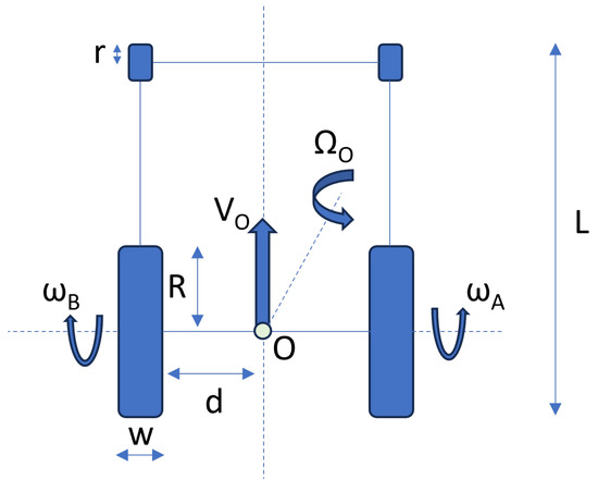
Figure 1.
Wheelchair’s geometrical representation.
As largely discussed in [15], we are going to take the same 3D wheelchair model used there. Table 1 provides information about the wheelchair’s dimensions.

Table 1.
Wheelchair’s components’ dimensions.
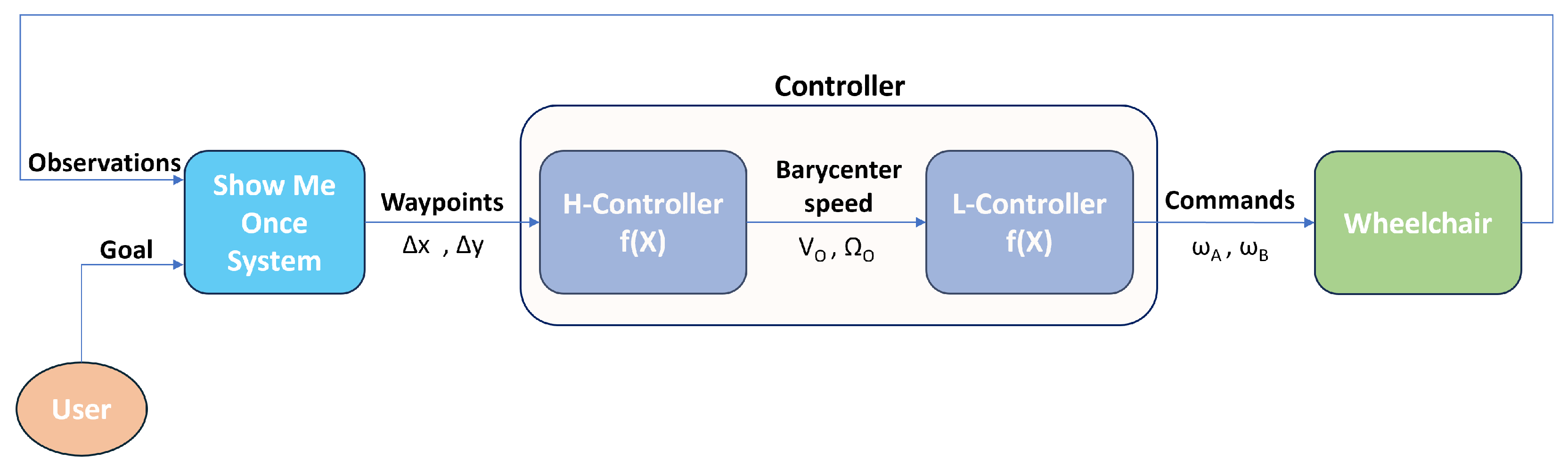
The Show Me Once System (SMOS) output will be in the form of waypoints, namely relative distances between the current position and the next one. The reason behind this design choice is to let the output be independent with respect to the robot, in our case the wheelchair. Obviously, the wheelchair low-level controller needs a pair of rotational speeds and to let the wheelchair move. For this reason, a higher controller is instantiated whose task is to translate the waypoints into rotational speeds by making use of the Model Predictive Control (MPC) technique. Figure 2 provides an overview of the controller hierarchy.
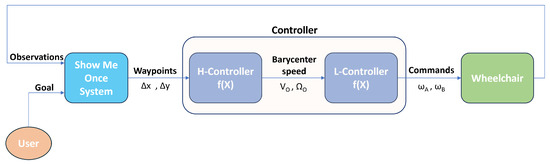
Figure 2.
Schematic representation of the system overview.
MPC is a sophisticated control method that forecasts and optimizes control actions across a future time horizon by using a mathematical model of the system. In the context of assisted driving for an electrified wheelchair, MPC is used to determine the optimal inputs that minimize a predefined cost function, considering both desired performance and the physical and operational constraints of the system [22,23]. The adoption of MPC offers numerous advantages over traditional low-level controls, such as proportional–integral–derivative (PID) control or fixed-rule closed-loop control. Firstly, MPC utilizes predictive optimization to anticipate the system’s future dynamics, calculating optimal control actions in advance. This approach allows for the compensation of potential disturbances or variations in system behavior, ensuring more responsive and precise control. Additionally, MPC can integrate the Field-Oriented Control (FOC) law, which is particularly effective for controlling alternating current motors [24,25]. FOC allows for direct control of motor torque and flux, enhancing system efficiency and the dynamic response. Another significant advantage of MPC is its ability to explicitly manage the system’s physical limitations, such as its current, voltage, and speed limits, ensuring safe and reliable operations while preventing overloads. The implementation of MPC significantly contributes to making the driving experience of the electrified wheelchair smoother and more comfortable. MPC reduces unwanted oscillations and vibrations that can arise from sudden changes in control inputs, resulting in more stable and continuous movement of the wheelchair. Transitions between different speeds or directions of movement are handled more gradually, avoiding abrupt changes in acceleration that could be uncomfortable for the user. Thanks to its predictive capability, MPC can quickly adapt to changes in operating conditions, such as variations in terrain or slope, ensuring more consistent and predictable driving and enhancing comfort and safety. Furthermore, MPC optimizes the response to user commands, ensuring the wheelchair follows directions accurately and smoothly and improving the overall driving experience. The implementation of MPC for the electric wheel motors of an electrified wheelchair offers numerous advantages in terms of driving smoothness and quality. Compared to traditional controls, MPC not only optimizes the system’s dynamic performance but also contributes to a more stable, comfortable, and safe driving experience, significantly improving the user’s experience.
2.3. Setup
The logic of the navigation system was constructed utilizing the Robotic Operating System (ROS), a well-established suite of software libraries and tools intended for the development of robotic applications. The popular open-source robotics simulator Gazebo was selected for the simulation because it has a strong physics engine and intuitive programmatic and graphical user interfaces. PyTorch, a Machine Learning framework widely used in many domains, such as robotics and Natural Language Processing, was used to create the neural networks. The fine-tuning of the foundational model was performed on a server equipped with 4 NVIDIA Tesla T4 [26], 264 GB of RAM, and an AMD EPYC 7301 16-core CPU [27]. A PC with an Intel Core i7-9750 H CPU, 16 GB of RAM, and an NVIDIA GTX 2080 graphics card was used to deploy the SMOS [28]. An NVIDIA Jetson Nano 2GB Developer Kit was used [29] to measure the inference time of the SMOS. For testing, we selected a driver without disabilities. Four trials are conducted: the first assesses the effectiveness of image retrieval and the ability of the SMOS to guide the wheelchair to the target; the second examines the relationship between the topology graph and system performance, noting that although the SMOS can operate without prior knowledge by generating the graph while attempting to reach the target, its performance improves when a prebuilt graph is provided; the third investigates the usability of the system in the presence of moving obstacles and ramps; and the fourth evaluates the system’s usability on an embedded or resource-constrained device. Every test was run through a minimum of three times, and the figures that are shown are the average of the data that were gathered. The standard deviation is also provided where applicable. To ensure statistical significance, the test for collecting the inference time counted 100 executions.
3. Show Me Once System Architecture
3.1. Workflow
The SMOS architecture consists of three modules: (i) Wheelchair Navigator, responsible for guiding the wheelchair toward the goal image; (ii) Goal Retrieval, offering the user the possibility to specify the goal by providing a description; and (iii) Episodic Memory, responsible for mitigating the issue of long-distance goals. An overview of the architecture can be found in Figure 3.
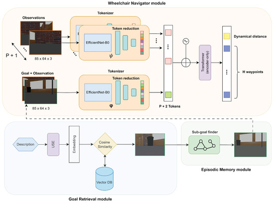
Figure 3.
Show Me Once System structure overview with submodules’ details.
Before deep-diving into the details of each module, we start by describing the logical workflow. To make it easier, we will specify it via a pseudo-code algorithm—see Algorithm 1.
| Algorithm 1 Pseudo-code for SMOS workflow. |
|
In particular, the users provide the description of the target place they would like to reach. Hence, the Goal Retrieval module processes it and yields an image whose description is the most similar to the one provided by the user. If the target location is determined to be distant based on the current observation, the Episodic Memory module produces a proximity goal, which eventually coincides with the actual goal. Using this proximity goal along with current and past observations, the Wheelchair Navigator module suggests the next H waypoints to reach the proximity goal, along with a dynamic distance. The controller then guides the wheelchair to these waypoints. The generation of new waypoints ceases once the current observation is, within certain thresholds, similar to the goal image.
3.2. Insights
Let us now deep-dive into each module. The Wheelchair Navigator module is an image–goal navigation system based on ViNT [20] and adapted for wheelchair navigation. The inputs are composed of a subgoal image and the visual observations —present and P past ones. The results consist of two components: the amount of time steps required to achieve the subgoal—named dynamic distance—and a series of H upcoming waypoints that guide the wheelchair toward the subgoal. The input includes the distinct observation images and the superimposition of the current observation and the subgoal image . This approach provides a brief summary of previous locations as context using the observation images, and it also provides a relative measurement of the disparity between the current observation and the subgoal. The core of the module is a Transformer, which requires tokenized input. The tokenization process involves encoding the images using an EfficientNet-B0 [30] encoder. An input image of is converted into a flattened feature vector . To reduce the vector components and thus reduce the computational effort required to process them, the feature vector is compressed through a feed-forward neural network to produce a token of 512 elements for each image. Given the different purposes of the observations and the superimposition of the current observation and the subgoal image , these two groups use distinct sets of EfficientNet-B0 encoders and feed-forward neural networks. At this point, the tokens are flattened and preprocessed through positional encoding to retain information about their order. They are then ready to be processed by the Transformer backbone. More precisely, the core is made up of a Transformer that only encodes, containing encoder blocks, each consisting of traditional operations such as multi-head attention with heads and a feed-forward layer with hidden units. Uniquely, in this implementation, normalization is performed before each of these operations rather than after.
In theory, we could input the goal image to the first submodule and let it guide the wheelchair toward the goal. However, in practice, when the goal is far from the current position, the module struggles to effectively guide the wheelchair to the destination. In order to tackle this issue, the Episodic Memory module upholds an Episodic Memory structured as a topological graph, offering short-term subgoals to reach remote locations. The topological graph contains nodes representing past environmental observations, and their connections are determined by the distance predicted by the previous module. Subsequently, subgoals are chosen using the A* algorithm [31].
Finally, the Goal Retrieval module is responsible for providing the goal image . To allow the users to describe in natural language the goal they would like to achieve, a text-based image search is implemented. Exploiting the topological graph built during navigation, the user can pinpoint a specific location by providing a description. The description is then transformed into an embedding vector by the Universal Sentence Encoder [32] text-embedding model. The embedding vector is then stored in a vector database. When the user wants to reach a specific place, by providing a description of the target, this will be turned into an embedding vector and a similarity search will be performed. In our case, by calculating the cosine similarity between the stored goal descriptions and the newly provided description, the closest stored description that reports a similarity score above the s threshold will be selected and the associated image will become the goal image.
3.3. Fine-Tuning
Our environment in which the SMOS is going to operate is simulated, unlike the environment in which the module guiding the wheelchair was originally trained. For this reason, this module requires fine-tuning. We achieve this by using the same training-objective function employed in training the foundational model, as detailed in the following equation:
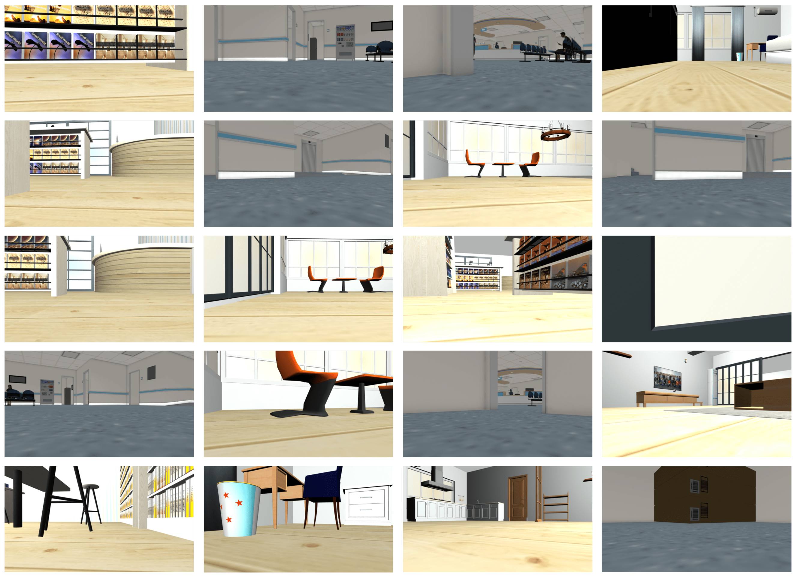
Specifically, given the dataset D, in every training epoch, we select , a minibatch of trajectories. Subsequently, we pick a random subgoal , where d is uniformly sampled from the range and P consecutive observations create the context . Additionally, we extract the H future actions from the dataset and use them, along with d, as labels. Since the model will output a and d, we use a maximum likelihood objective to adjust the parameters involved in their generation, namely given by the Transformer and and for, respectively, the observation tokenizer and the goal tokenizer, using to balance the losses. We collected approximately 1.5 h of simulated trajectories in several environments, including speed and odometry information. Camera images were sampled at a rate of 1 Hz, forming our dataset. Examples of observations are in Figure A1.
3.4. Waypoints Generations
The pretrained navigator module was trained on robots of various sizes, speeds, and dynamics. To accommodate this diversity, an embodiment-agnostic action space was selected. Specifically, relative waypoints are used as the action space instead of low-level controls. To account for speed variance, these waypoints are normalized based on each robot’s top speed. During deployment, the Wheelchair Navigator module receives visual observations and a subgoal, which is determined by the execution of the A* algorithm over the topological graph. The dynamical distance d is used to update the topological graph, while the actions guide the wheelchair toward the subgoal. A robot-specific controller un-normalizes and tracks these waypoints using low-level controls. Once the model reaches the subgoal, a new iteration begins, a new subgoal is selected, and the process continues until the final goal is reached.
3.5. Software Infrastructure
The software infrastructure is made up of several elements that are spread throughout the different levels of the technology stack. The Wheelchair Navigator module was implemented using PyTorch [33] and consists of the tokenizers and Transformer classes. Specifically, they employ the EfficientNet and TransformerEncoderLayer PyTorch implementations, respectively. The Goal Retrieval module is composed of a sentence embedder and a vector database. For the sentence embedder, the Universal Sentence Encoder [32] text-embedding model was employed due to its good performance and open-source availability. For the vector database, Chroma [34] was selected because of its native support for embedding storage and open-source availability. However, other solutions can be used for both the embedding model and vector database. The logic implementation utilized the LangChain framework [35]. The Wheelchair Navigator module yields waypoints. To transform waypoints into barycenter speeds for wheelchair motion, a PD controller using MPC is implemented. This is identified as the H-Controller due to its higher-level nature compared to the L-Controller, which effectively considers the dynamics of the wheelchair and its actuators. To realize the tasks related to wheelchair navigation, the ROS was employed. For safety reasons, while the wheelchair is guided by the SMOS, it can still be controlled by the user or recovery procedures thanks to collision sensors. To avoid command overlap, the wheelchair controller employs a speed multiplexer that selects the highest-priority available command: in order, recovery procedures, user input, and H-Controller output. A simulator was used for the fine-tuning and testing of the Wheelchair Navigator module. In particular, Gazebo was chosen because of the smooth integration in the ROS, which was used to implement the wheelchair-navigation tasks.
4. Simulations
The Wheelchair Navigator module relies on the ViNT [20] foundational model. The foundational model was trained on real observation data and achieved promising results. However, our environment is a simulated one, so the vanilla (i.e., without fine-tuning) version will not perform best. For this reason, we performed a fine-tuning of the model based on three different environments filled with obstacles with different shapes and dynamics, as depicted in Figure 4.
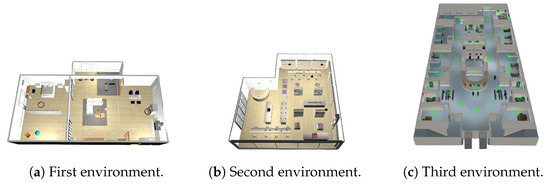
Figure 4.
Environments used for SMOS fine-tuning.
We collected observations at the frequency of 1 Hz for a total of approximately 1.5 h. To facilitate generalization, Gaussian noise was added to the sensors. To validate the effectiveness of the fine-tuned system, we decided to compare the SMOS with and without fine-tuning. For the sake of comparison, we provide both systems with the same topological graph. To be able to compare them, we collect the following metrics:
- Goal-reaching time—the time needed from the instant in which the system receives the goal image till the instant in which the wheelchair reaches the goal;
- Collision risk—the number of occurred collisions.
For each environment depicted in Figure 5, the metrics are calculated over three executions. Table 2 presents the test results.
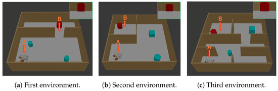
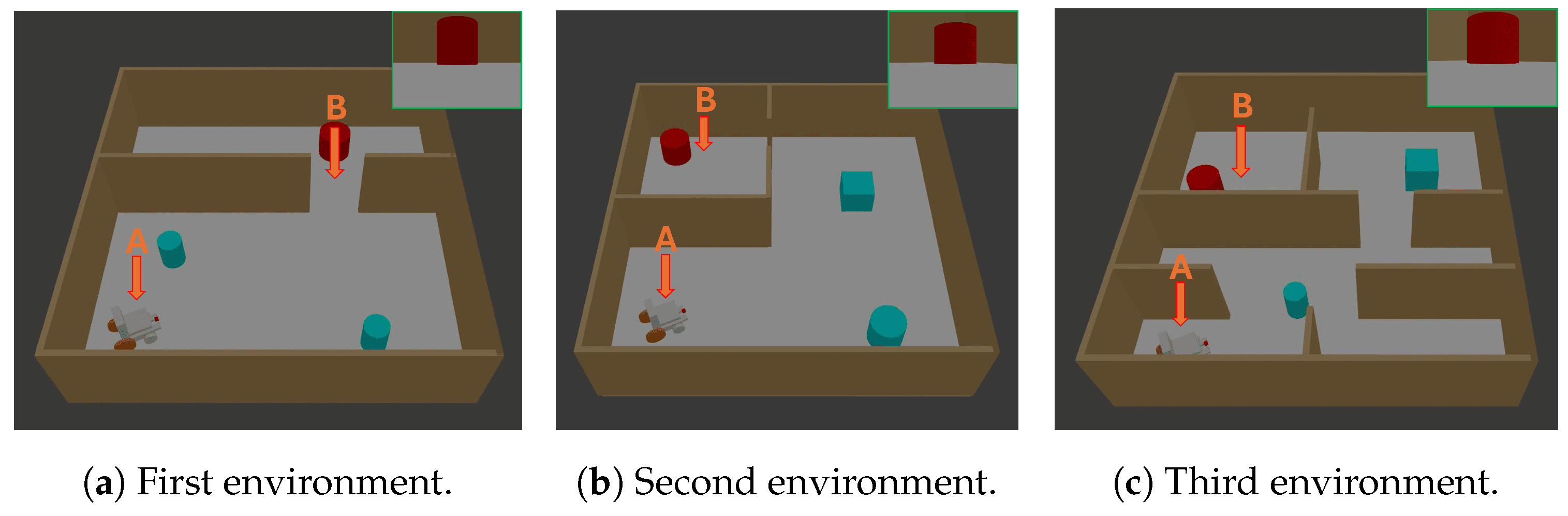
Figure 5.
In all the environments, point A and B represent, respectively, the starting position and the location where the target image (green frame) was captured. The system is provided with the target image as input, and the objective is to observe how the system navigates the wheelchair from point A to point B. The tests are arranged in order of increasing difficulty, from the easiest to the most challenging.
Table 2.
Result of first experiment.
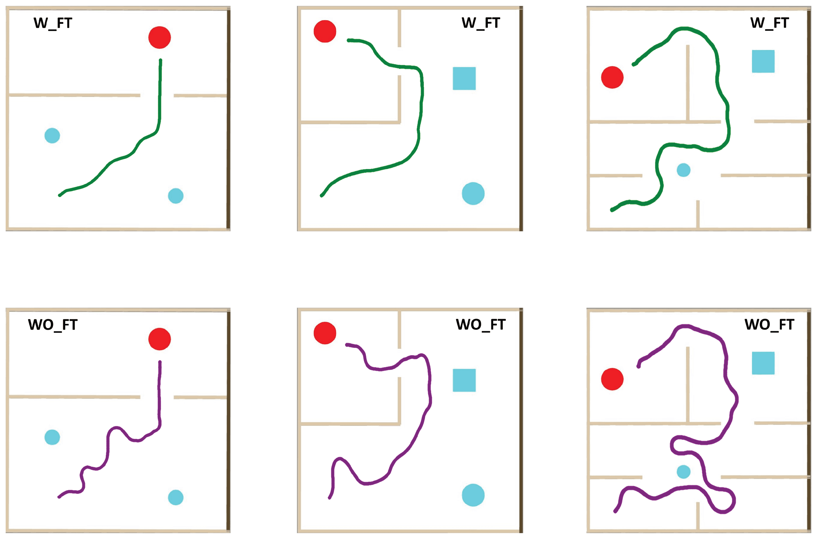
Trajectory samples can be found in Figure A2. The effectiveness of the SMOS depends highly on the Episodic Memory module. A rich topological graph allows the system to better plan the trajectory, and sometimes, by traversing the graph, it could even find that shortcuts spawned due to the obstacles’ disposition change that was not present during the first exploration. However, it comes with the storage price. The amount of images that can be stored depends on the storage resource availability. Defining the performance of the system as how fast the wheelchair is reaching the goal, we take as reference the performance obtained with a “rich” topological graph. The definition of “rich” is not easy to measure since it depends on the environment. However, we tried to estimate it for the environments depicted in Figure 5. We then created the topological graphs by navigating in those environments by randomly generating waypoints for a variable amount of time , where depends on the environment. The size S of the topological graph is linearly dependent on the time t according to the following equation:
where is the acquisition frequency, is the image size, is the embedding size of the transformed description, and t is the time that elapsed since the beginning of the graph creation. Once obtained, taking the fine-tuned SMOS, we instantiate one system per each topological graph and give them the same goal. We then measure the performance in terms of goal-reaching time with respect to the reference one, namely the one with a “rich” topological graph. Figure 6 presents the results.
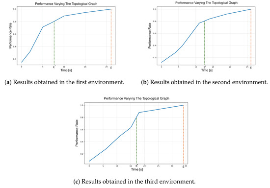
Figure 6.
Results related to the performance against the topological graph experiment. For all three graphs, the Y-axis shows the ratio of the current performance, given by a specific topological graph, to the performance provided by a “rich” topological graph for that environment. The X-axis represents the time spent building the topological graph. The orange line indicates the performance reference at , while the green line marks , the point at which the system reaches 80% of the performance of a “rich” graph.
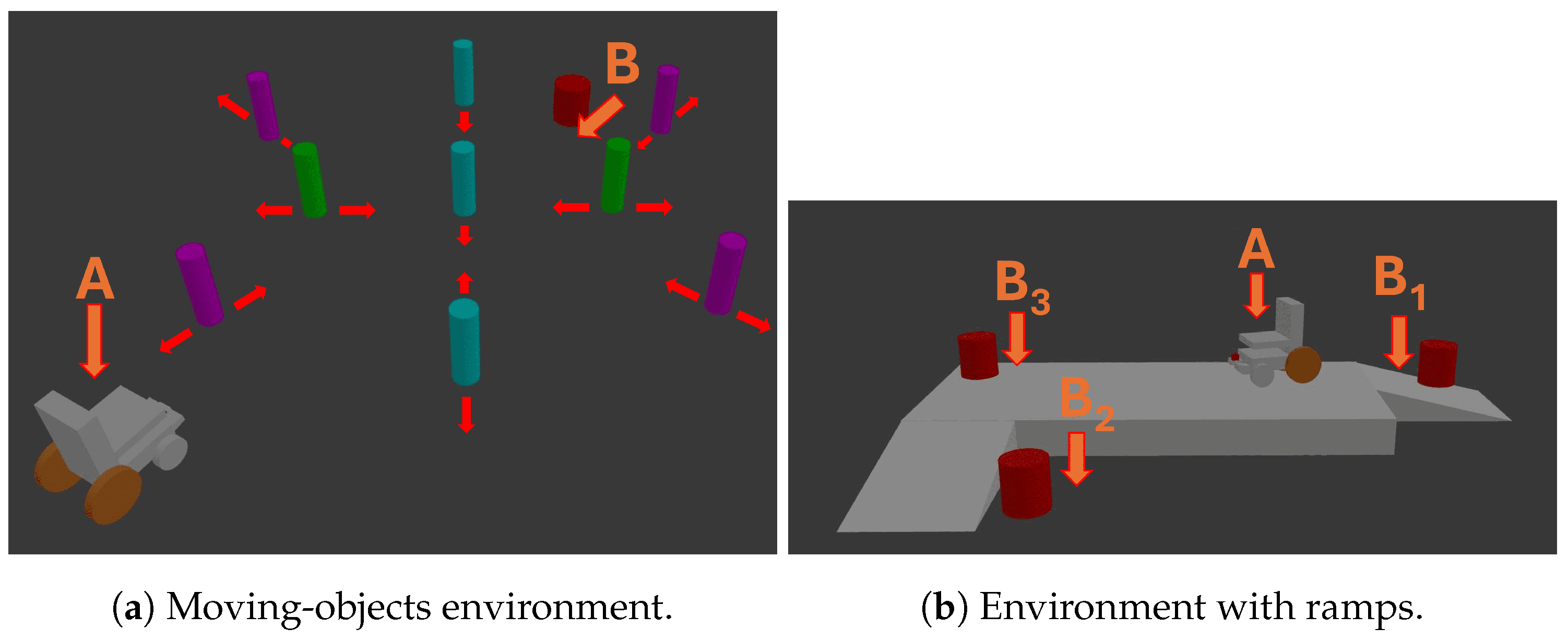
Another important feature to test is the ability to navigate outdoors. In outdoor scenarios, the presence of moving objects and ramps may compromise the safety of the system. For this reason, we decided to test the system against both obstacles. By using the fine-tuned system, we tested it in the environments depicted in Figure 7.
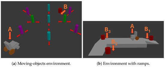
Figure 7.
In all the environments, points A and B(x) represent, respectively, the starting position and the location where the target image was captured. The system is provided with the target image as input, and the objective is to observe if the system is able to avoid collisions. For the moving objects, each object moves according to the arrows. For the environment with ramps, multiple goals are evaluated.
The result we are interested in is the ability to reach the goal and to avoid collisions. For the moving-obstacles test, we analyzed the system’s behavior as the obstacles’ speed varied. Regarding the environment with ramps, we tested the system with and without a simulation constraint to ban areas in the proximity of the curbs. The results can be found in Figure 8.
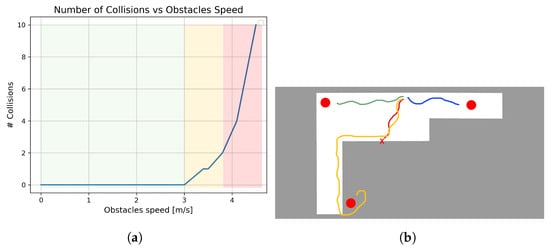
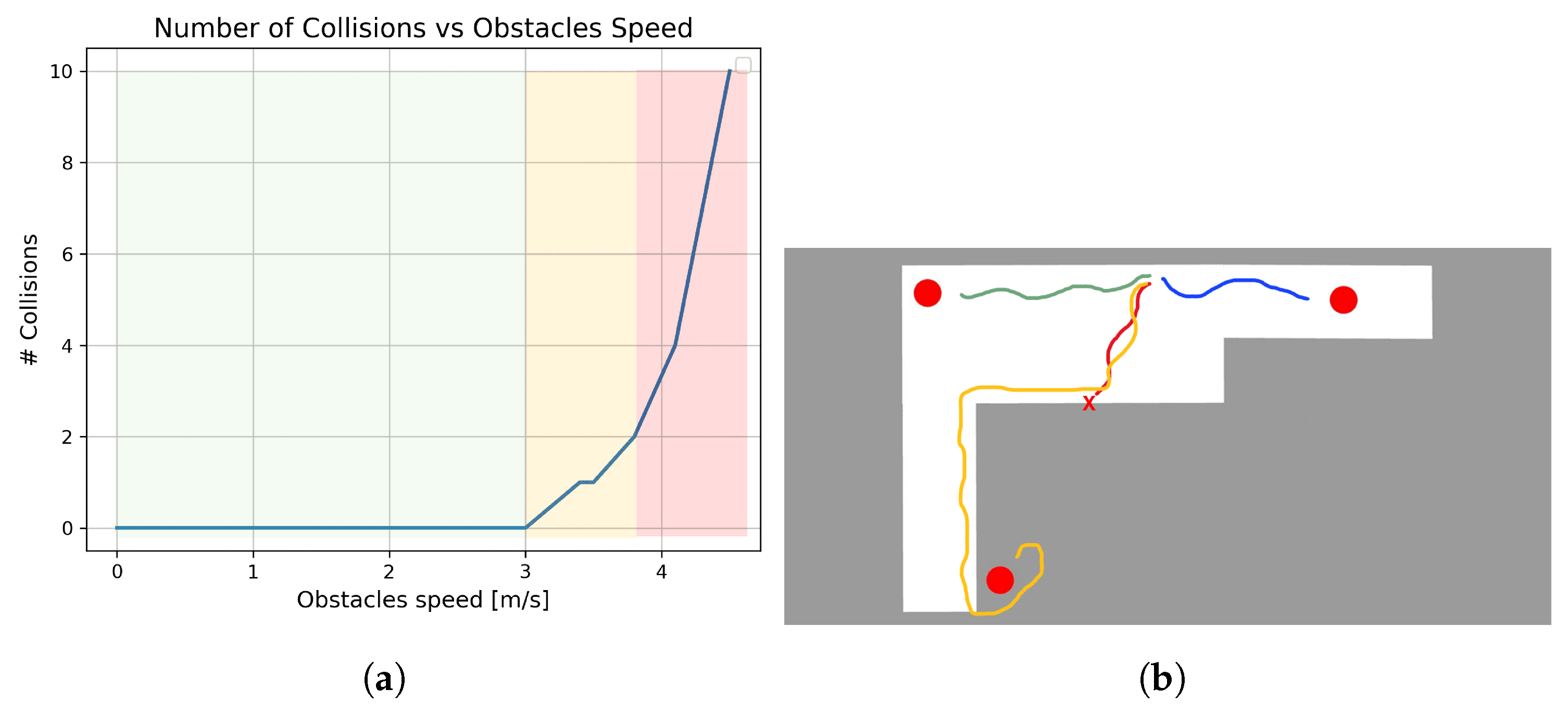
Figure 8.
Moving-obstacles environment: the number of collisions tends to be infinite as the speed exceeds roughly 4 m/s (red area). Ramps environment: the red trajectory terminates with an overturning; the orange one is related to the usage of banned areas around curbs. (a) Moving objects’ graph result. (b) Trajectories in the environment with ramps.
Ultimately, the goal is to deploy the system on a real wheelchair. For this reason, we decided to compare the performances of the system deploying it on an unconstrained device [28] and on a constrained device, in particular an NVIDIA Jetson Nano 2 GB Developer Kit [29]. As a metric, we collected the inference time of the SMOS. We deployed only the Wheelchair Navigator module because the execution times of the Goal Retriever and the Episodic Memory module are a few orders of magnitude less than the Wheelchair Navigator itself. The result of the test can be found in Table 3.
Table 3.
Inference execution results across various computing devices.
5. Results and Discussion
The investigations looked into several facets of the SMOS. The first experiment showed how the fine-tuning procedure affected performance in three different situations, ranging from the easiest to the most difficult, by comparing the performance of the basic system with the fine-tuned version. Notably, the fine-tuned system saw average reductions in goal-reaching time of 13%, 15%, and 29%, which can be attributed to smoother navigation and better planning. In terms of collision avoidance, both systems performed well in the first two environments; however, only the fine-tuned system achieved the zero-collision objective in the third environment. This improvement is due to the domain mismatch in the vanilla system, trained on real images, and the fine-tuned ones, trained on a simulated environment. Despite this, the vanilla system still performed relatively well, demonstrating the robustness of the foundational model in providing good wheelchair navigation and sufficient collision avoidance. A notable feature of the system is related to the fine-tuning process and its connection to the concept of a foundational model: thanks to its architecture and effective pretraining phase, the fine-tuning process achieved excellent results with only 1.5 h of collected observations.
In the second experiment, the impact of the topological graph on performance in terms of goal-reaching time was analyzed. Due to the linear relationship between the graph and its size, the longer the system operates, the larger the topological graph becomes, enhancing system performance. However, storing the topological graph incurs a storage cost as it requires saving snapshots collected via the on-board camera along with some odometry information. Depending on hardware availability, a tradeoff may be necessary. The results indicate that while the exact behavior depends on the environment, a trend is evident. The most significant performance enhancement occurs when the system transitions from having no graph to having some connected nodes. Subsequently, the impact of the topological graph on performance increases at a slower rate, suggesting that in cases of storage limitation, a proper tradeoff between target performance and storage usage should be determined, likely leaning toward fewer nodes. For reference, aiming for a balance between performance and storage, the system often reaches 80% of the performance that a rich graph would provide at a time , which depends on the environment’s complexity but is on average less than half of , potentially saving at least 50% in storage space.
The third experiment assessed the system’s usability in outdoor environments. The results highlighted three key areas. In the left-most area, where obstacles moved at speeds below 3.2 m/s, the system reported no collisions. This is a positive outcome, particularly considering the worst-case scenario of a pedestrian moving at a maximum speed of 1.5 m/s walking toward the wheelchair, which navigates at a maximum speed of 1 m/s. However, as obstacle speed increases, the system begins to report some collisions, entering the more dangerous second area. As expected, there is an upper threshold beyond which the system can no longer prevent collisions, and this area should be avoided. This threshold is determined by the combination of the maximum speeds (both linear and angular) set on the controller and the operating rate of the Wheelchair Navigator module. In theory, this limit could be extended by increasing these values, but safety considerations and available computing resources must be taken into account. Overall, the system appears to have inherited the ability to avoid moving obstacles from the foundational model. For the test involving ramps, the system without restrictions reported one instance of overturning. In contrast, the system with banned areas exhibited an excellent performance, with no collisions. Finding the reason why the system struggles to detect these kinds of obstacles is far from simple. Certainly, these kinds of obstacles are not present in the fine-tuning we performed and are rare in the foundational model dataset. Further investigation is required, but promising results from previous work [6] might support the decision to incorporate a banned-area constraint.
Regarding inference time, the fourth experiment highlighted the system’s suitability for deployment on embedded devices. However, it is important to note that even though the embedded device used has limited resources, it is still equipped with a GPU. Empirical evidence suggests that for a smooth user experience, the Wheelchair Navigator module should run at a frequency of at least 6 Hz. The low inference time then offers a good margin for model improvement.
6. Conclusions
Traditional Deep Reinforcement Learning often struggles with designing reward functions for multi-objective optimization. The recent usage of the Transformer in the reinforcement learning framework prefigures a significant advancement in this domain. The Transformer architecture enables it to “absorb” policies through a composite dataset, allowing fine-tuning for downstream applications with significantly less data. This innovation poses the basis for foundational models in robotics, particularly for wheelchairs, enabling the development of more effective and versatile policies. This study demonstrates how a foundational model like ViNT can be fine-tuned to assist wheelchair navigation, creating an assistive driving system where users can specify their target location through a description. While the results are preliminary, they are promising. However, there are limitations, as the testing did not include people with disabilities and was conducted only in a simulated environment. Future research will address these limitations and expand comparisons with existing navigation systems.
Author Contributions
Conceptualization, F.P. and L.F.; methodology, F.P.; software, F.P.; validation, F.P., P.D., and L.F.; formal analysis, F.P.; investigation, F.P.; resources, F.P., P.D., and L.F.; data curation, F.P.; writing—original draft preparation, F.P.; writing—review and editing, F.P., P.D., and L.F.; visualization, F.P.; supervision, F.P.; project administration, F.P. and L.F.; funding acquisition, L.F. All authors have read and agreed to the published version of the manuscript.
Funding
This study was partially supported by the Italian Ministry of Education and Research (MUR), Act 11 December 2016, n. 232, in the framework of the FoReLab project (Department of Excellence).
Data Availability Statement
The foundational model can be retrieved with the following link: https://drive.google.com/file/d/1ckrceGb5m_uUtq3pD8KHwnqtJgPl6kF5/view?usp=drive_link (accessed on 9 September 2024).
Conflicts of Interest
The authors declare no conflicts of interest.
Appendix A
Parameters list for SMOS in the testing phase.
Table A1.
Parameters of SMOS employed in simulation.
Table A1.
Parameters of SMOS employed in simulation.
| Parameters | Value |
|---|---|
| P | 5 |
| H | 5 |
| 2 | |
| 2 | |
| 4 | |
| −3 | |
| 3 | |
| 0.5 |
Extra information about the fine-tuning procedure.
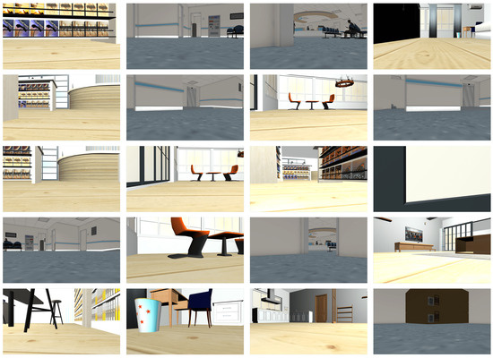
Figure A1.
Sample of images collected during training.
Figure A1.
Sample of images collected during training.
Appendix B
Additional content regarding the first experiment execution.

Figure A2.
Trajectory samples during the experiment, which compared the fine-tuned system (W_FT) against the vanilla one (WO_FT).
Figure A2.
Trajectory samples during the experiment, which compared the fine-tuned system (W_FT) against the vanilla one (WO_FT).
References
- World Health Organization; World Bank. World Report on Disability 2011; World Health Organization, World Bank: Geneva, Switzerland, 2011. [Google Scholar]
- Mars, L.; Arroyo, R.; Ruiz, T. Mobility and wellbeing during the COVID-19 lockdown. Evidence from Spain. Transp. Res. Part A Policy Pract. 2022, 161, 107–129. [Google Scholar] [CrossRef] [PubMed]
- Freedman, V.A.; Carr, D.; Cornman, J.C.; Lucas, R.E. Aging, mobility impairments and subjective wellbeing. Disabil. Health J. 2017, 10, 525–531. [Google Scholar] [CrossRef] [PubMed]
- Arroyo, R.; Mars, L.; Ruiz, T. Activity Participation and wellbeing during the covid-19 lockdown in Spain. Int. J. Urban Sci. 2021, 25, 386–415. [Google Scholar] [CrossRef]
- Comai, S.; De Bernardi, E.; Matteucci, M.; Salice, F. Maps for Easy Paths (MEP): Enriching Maps with Accessible Paths Using MEP Traces. In Proceedings of the Smart Objects and Technologies for Social Good, Venice, Italy, 30 November–1 December 2017; pp. 254–263. [Google Scholar]
- Pacini, F.; Dini, P.; Fanucci, L. Cooperative Driver Assistance for Electric Wheelchair. In Proceedings of the International Conference on Applications in Electronics Pervading Industry, Environment and Society; Springer: Berlin/Heidelberg, Germany, 2023; pp. 109–116. [Google Scholar]
- Mnih, V.; Kavukcuoglu, K.; Silver, D.; Graves, A.; Antonoglou, I.; Wierstra, D.; Riedmiller, M. Playing atari with deep reinforcement learning. arXiv 2013, arXiv:1312.5602. [Google Scholar]
- Chen, L.; Hu, X.; Tang, B.; Cheng, Y. Conditional DQN-based motion planning with fuzzy logic for autonomous driving. IEEE Trans. Intell. Transp. Syst. 2020, 23, 2966–2977. [Google Scholar] [CrossRef]
- Li, J.; Chen, Y.; Zhao, X.; Huang, J. An improved DQN path planning algorithm. J. Supercomput. 2022, 78, 616–639. [Google Scholar] [CrossRef]
- Okuyama, T.; Gonsalves, T.; Upadhay, J. Autonomous driving system based on deep q learnig. In Proceedings of the 2018 IEEE International conference on intelligent autonomous systems (ICoIAS), Singapore, 1–3 March 2018; pp. 201–205. [Google Scholar]
- Zhang, W.; Gai, J.; Zhang, Z.; Tang, L.; Liao, Q.; Ding, Y. Double-DQN based path smoothing and tracking control method for robotic vehicle navigation. Comput. Electron. Agric. 2019, 166, 104985. [Google Scholar] [CrossRef]
- Wu, K.; Wang, H.; Esfahani, M.A.; Yuan, S. Bnd*-ddqn: Learn to steer autonomously through deep reinforcement learning. IEEE Trans. Cogn. Dev. Syst. 2019, 13, 249–261. [Google Scholar] [CrossRef]
- Xue, X.; Li, Z.; Zhang, D.; Yan, Y. A deep reinforcement learning method for mobile robot collision avoidance based on double dqn. In Proceedings of the 2019 IEEE 28th International Symposium on Industrial Electronics (ISIE), Vancouver, BC, Canada, 12–14 June 2019; pp. 2131–2136. [Google Scholar]
- Tai, L.; Paolo, G.; Liu, M. Virtual-to-real deep reinforcement learning: Continuous control of mobile robots for mapless navigation. In Proceedings of the 2017 IEEE/RSJ International Conference on Intelligent Robots and Systems (IROS), Vancouver, BC, Canada, 24–28 September 2017; pp. 31–36. [Google Scholar]
- Pacini, F.; Dini, P.; Fanucci, L. Design of an Assisted Driving System for Obstacle Avoidance Based on Reinforcement Learning Applied to Electrified Wheelchairs. Electronics 2024, 13, 1507. [Google Scholar] [CrossRef]
- Ibarz, J.; Tan, J.; Finn, C.; Kalakrishnan, M.; Pastor, P.; Levine, S. How to train your robot with deep reinforcement learning: Lessons we have learned. Int. J. Robot. Res. 2021, 40, 698–721. [Google Scholar] [CrossRef]
- Vaswani, A.; Shazeer, N.; Parmar, N.; Uszkoreit, J.; Jones, L.; Gomez, A.N.; Kaiser, Ł.; Polosukhin, I. Attention is all you need. Adv. Neural Inf. Process. Syst. 2017, 30. Available online: https://papers.nips.cc/paper_files/paper/2017/hash/3f5ee243547dee91fbd053c1c4a845aa-Abstract.html (accessed on 9 September 2024).
- Chen, L.; Lu, K.; Rajeswaran, A.; Lee, K.; Grover, A.; Laskin, M.; Abbeel, P.; Srinivas, A.; Mordatch, I. Decision transformer: Reinforcement learning via sequence modeling. Adv. Neural Inf. Process. Syst. 2021, 34, 15084–15097. [Google Scholar]
- Brohan, A.; Brown, N.; Carbajal, J.; Chebotar, Y.; Dabis, J.; Finn, C.; Gopalakrishnan, K.; Hausman, K.; Herzog, A.; Hsu, J.; et al. Rt-1: Robotics transformer for real-world control at scale. arXiv 2022, arXiv:2212.06817. [Google Scholar]
- Shah, D.; Sridhar, A.; Dashora, N.; Stachowicz, K.; Black, K.; Hirose, N.; Levine, S. Vint: A foundation model for visual navigation. arXiv 2023, arXiv:2306.14846. [Google Scholar]
- Pacini, F.; Di Matteo, S.; Dini, P.; Fanucci, L.; Bucchi, F. Innovative Plug-and-Play System for Electrification of Wheel-Chairs. IEEE Access 2023, 11, 89038–89051. [Google Scholar] [CrossRef]
- Cosimi, F.; Dini, P.; Giannetti, S.; Petrelli, M.; Saponara, S. Analysis and design of a non-linear MPC algorithm for vehicle trajectory tracking and obstacle avoidance. In Proceedings of the Applications in Electronics Pervading Industry, Environment and Society: APPLEPIES 2020 8; Springer: Berlin/Heidelberg, Germany, 2021; pp. 229–234. [Google Scholar]
- Dini, P.; Saponara, S. Processor-in-the-Loop Validation of a Gradient Descent-Based Model Predictive Control for Assisted Driving and Obstacles Avoidance Applications. IEEE Access 2022, 10, 67958–67975. [Google Scholar] [CrossRef]
- Bernardeschi, C.; Dini, P.; Domenici, A.; Saponara, S. Co-simulation and verification of a non-linear control system for cogging torque reduction in brushless motors. In Proceedings of the Software Engineering and Formal Methods: SEFM 2019 Collocated Workshops: CoSim-CPS, ASYDE, CIFMA, and FOCLASA, Oslo, Norway, 16–20 September 2019; Revised Selected Papers 17. Springer: Berlin/Heidelberg, Germany, 2020; pp. 3–19. [Google Scholar]
- Bernardeschi, C.; Dini, P.; Domenici, A.; Palmieri, M.; Saponara, S. Formal verification and co-simulation in the design of a synchronous motor control algorithm. Energies 2020, 13, 4057. [Google Scholar] [CrossRef]
- NVIDIA Teslta T4 Datasheet. Available online: https://www.nvidia.com/content/dam/en-zz/Solutions/Data-Center/tesla-t4/t4-tensor-core-datasheet-951643.pdf (accessed on 23 May 2024).
- AMD Epyc Server CPU Family. Available online: https://www.amd.com/en/processors/epyc-server-cpu-family (accessed on 23 May 2024).
- Asus. Asus Rog Zephyrus GX502; Asus: Taiwan, China, 2019. [Google Scholar]
- NVIDIA. Jetson Nano 2GB Developer Kit; NVIDIA: Santa Clara, CA, USA, 2020. [Google Scholar]
- Tan, M.; Le, Q. Efficientnet: Rethinking model scaling for convolutional neural networks. In Proceedings of the International Conference on Machine Learning, PMLR, Long Beach, CA, USA, 9–15 June 2019; pp. 6105–6114. [Google Scholar]
- Hart, P.; Nilsson, N.; Raphael, B. A Formal Basis for the Heuristic Determination of Minimum Cost Paths. IEEE Trans. Syst. Sci. Cybern. 1968, 4, 100–107. [Google Scholar] [CrossRef]
- Cer, D.; Yang, Y.; Kong, S.y.; Hua, N.; Limtiaco, N.; John, R.S.; Constant, N.; Guajardo-Cespedes, M.; Yuan, S.; Tar, C.; et al. Universal sentence encoder. arXiv 2018, arXiv:1803.11175. [Google Scholar]
- Paszke, A.; Gross, S.; Massa, F.; Lerer, A.; Bradbury, J.; Chanan, G.; Killeen, T.; Lin, Z.; Gimelshein, N.; Antiga, L.; et al. Pytorch: An imperative style, high-performance deep learning library. Adv. Neural Inf. Process. Syst. 2019, 32, 8026–8037. [Google Scholar]
- Chroma Vector Database. Available online: https://www.trychroma.com/ (accessed on 5 June 2024).
- LangChain Framework. Available online: https://www.langchain.com/ (accessed on 5 June 2024).


Disclaimer/Publisher’s Note: The statements, opinions and data contained in all publications are solely those of the individual author(s) and contributor(s) and not of MDPI and/or the editor(s). MDPI and/or the editor(s) disclaim responsibility for any injury to people or property resulting from any ideas, methods, instructions or products referred to in the content. |
© 2024 by the authors. Licensee MDPI, Basel, Switzerland. This article is an open access article distributed under the terms and conditions of the Creative Commons Attribution (CC BY) license (https://creativecommons.org/licenses/by/4.0/).