2. Configuration of the Proposed Wireless Battery Charging System for a Quadcopter
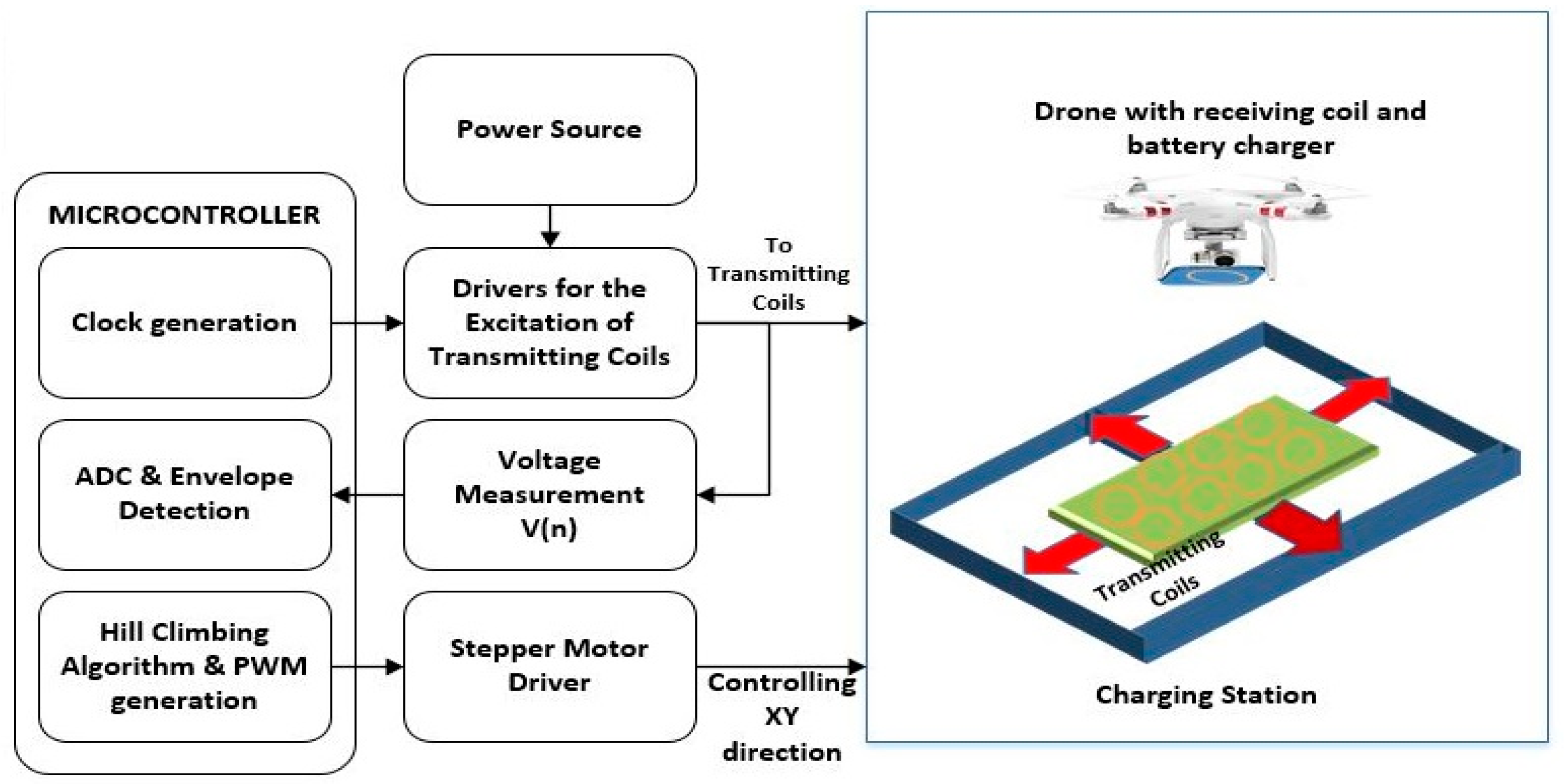
Figure 1 shows the proposed wireless battery charging system for a quadcopter. The system is composed of the following three parts:
Wireless power transmitter, comprising transmitting coil array which can move in four directions.
Wireless power receiver, a receiving coil, and battery charger.
Control unit which can measure the terminal voltage of each transmitting coil, and align the centroid of the transmitting and receiving coil using the hill climbing algorithm.
The proposed wireless battery charging system consists of multiple transmitting coils which can be moved in four directions (positive
X-direction, negative
X-direction, positive
Y-direction, and negative
Y-direction). The use of multiple coils can potentially allow the system to efficiently adapt to magnetic field propagation conditions, similar to the way multiple antennas are used to adapt to channel conditions in wireless communication systems [
38]. Also, multiple transmitting coils decrease the time for coil alignment, providing a chance for the design of big charging stations for large drones, where coil size and design are limited due to power transmission characteristics. In this proposed system, if a drone with a receiving coil lands at any position on the multiple transmitting coils, the voltages across the transmitting coils decrease depending on the coupling of each transmitting coil with the receiver coil, and the controller knows where the drone lands by observing the change in terminal voltages of the multiple coils. When the power is transferred from the transmitting coil to the receiving coil, the terminal voltage of the transmitting coil tends to decrease due to the phenomenon called signal backscattering. By observing the backscattered signal from each transmitting coil, the controller automatically knows which transmitting coil is nearest to the receiving coil. If the controller pinpoints the nearest transmitting coil, the multiple transmitting coil array is moved to automatically align the centroid of the detected transmitting coil with that of the receiving coil using the hill climbing algorithm. The practical system used to implement the proposed system comprises a receiver circuit for battery recharging and a power transmission station.
2.1. Transmitter and Receiver Circuit Design and Description
Figure 2 shows a simple wireless power transmission circuit. The circuit comprises a transmitter circuit, a receiving circuit, and the control part (voltage divider and analog-to-digital converter (ADC) of the microcontroller). The power amplifier drives the transmitting coil
. When the receiving coil is brought near to the transmitting coil, the voltage at receiving coil
is induced and it is processed by a bridge rectifier to convert AC to DC voltage. To achieve the optimum performance, values of
and
are calculated using Equations (1) to (4).
In the above equations,
is the mutual inductance,
is the coupling factor,
is the quality factor between the transmitting and receiving coils, and
is the phase angle ranging from 40° to 70°. The derivation of the equations for a Class-E amplifier can be found in Reference [
39]. Transmitting coils and the receiving coil are made of copper wire with 15 and 40 turns, respectively (
Table 1 and
Table 2). According to the power transmission range capabilities, wireless power transmission can be categorized into three types [
40,
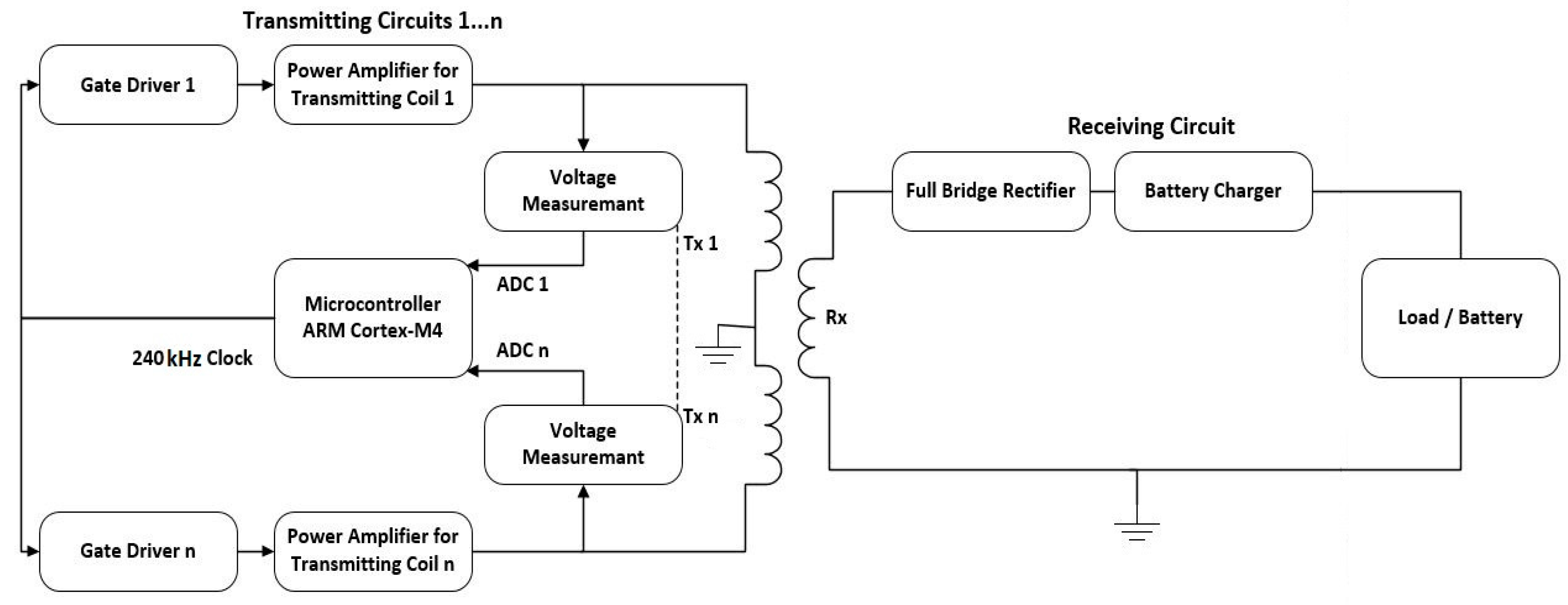
41]. First is the inductive power transmission (IPT) and capacitive power transmission (CPT), used for short-range distances; second is the resonant inductive coupling power transmission, widely used for medium-range distances; and third is the laser beam or microwave power transmission, used for long-range distances. In order to achieve high efficiency, inductive coupling requires very close coupling between the transmitting and receiving coil. Whereas, in resonant inductive coupling, efficient power transmission can be achieved with some distance between the transmitting and receiving coil via the use of resonant circuits. Also, resonant inductive coupling has better tolerance than inductive coupling. Therefore, the resonant inductive coupling is considered an effective technique for coping with the coil misalignment issues, and for drone battery charging systems. Therefore, in this work, a resonance inductive coupling-based wireless power transmission technique was used for charging the drone battery. The detailed block diagram of the circuit for wireless power transmission is shown in
Figure 3. At the transmitter side, Class-E power amplifiers are used to generate amplified AC voltages with a resonance frequency of 240 kHz for each coil.
These amplifiers are driven by a high-frequency clock signal. The clock signal is provided to the gate driver of each amplifier of the respective transmitting coil simultaneously. A microcontroller is used for generating a high-frequency clock signal and it keeps measuring the output voltages of each transmitting coil using an ADC, and performs envelop detection of the measured voltages to identify which excitation coil is the closest to the receiving coil of the drone.
At the receiving side, the receiving coil is installed on the drone and it is connected to a full bridge rectifier, which is used to convert the AC to DC. Finally, a battery charger (DC to DC converter) is used for battery charging. The system works by detecting the change in the voltage of any of the envelope-detected voltage signals of the transmitting coils, which (changes in voltage) refer to the presence of the receiving coil on the charging station. After detecting the receiving coil, a control algorithm is activated to align the coils and start wireless power transmission.
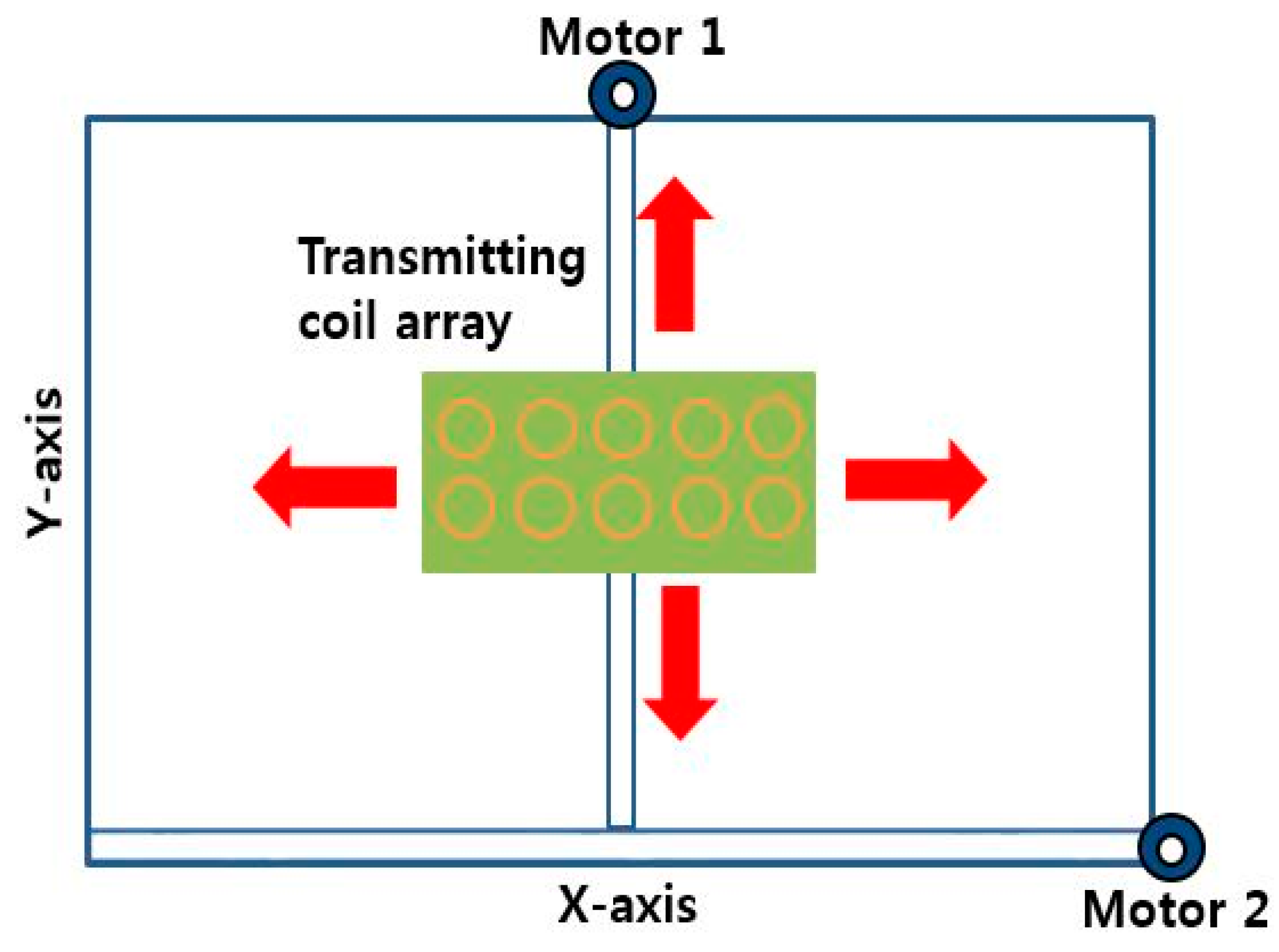
2.2. Four-Way Directional XY Table
A four-way directional
XY table was constructed to control the position of the transmitting coil array, as shown in
Figure 4. The
XY table is controlled by two stepper motors that are driven by two stepper motor drivers. Motor 1 is responsible for moving the transmitting coil array in the
Y-direction, while motor 2 is responsible for moving it in the
X-direction. When the quadcopter approaches the charging station, the transmitting coil, already excited having a constant voltage, experiences a change in voltage. This change in voltage refers to the presence of the receiving coil and load (battery). By measuring the voltage change from each transmitting coil, the charging station is moved in a direction where one of the transmitting coils is aligned to the receiving coil. The controller sends the required pulse width modulation (PWM) signals to the stepper motor driver to move the transmitting coil array to the proper position to initiate the wireless power transmission and battery charging.
2.3. Control Part
The control part of the proposed system performs specific tasks such as generating the clock signal for driving transmitting coils, monitoring each coil’s terminal voltage, and controlling the four-way XY table to align the centroids of the transmitting and receiving coils.
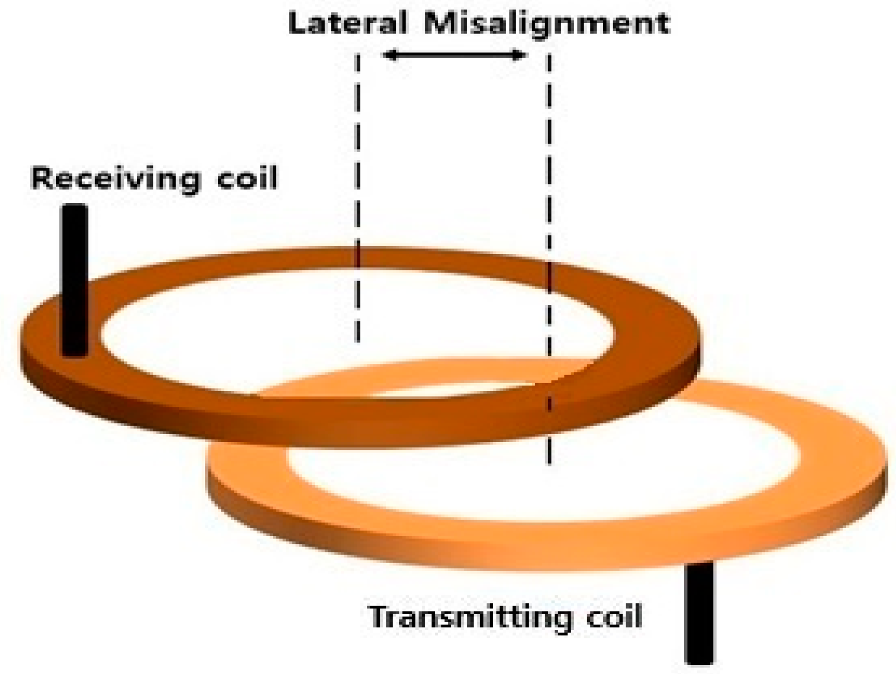
Generally, it is not easy to land a drone at a specific point on the drone station precisely. In most cases, the centroids of the transmitting and receiving coil are misaligned, as shown in
Figure 5.
When the misalignment between the coils happens, the efficiency of the wireless power transmission deteriorates. In order to solve this problem, an intelligent automatic alignment algorithm based on the hill climbing algorithm is proposed and implemented.
The automatic alignment algorithm was implemented inside a microcontroller. The microcontroller keeps measuring the terminal voltages of each transmitting coil simultaneously, and finds out which transmitting coil has the lowest voltage. Generally, when the receiving coil of the drone is near to a certain transmitting coil, the corresponding transmitting coil’s terminal voltage tends to decrease. Therefore, the microcontroller can detect the transmitting coil with a voltage difference and, from this moment on, the microcontroller tries to align the centroid of the transmitting coil with the receiving coil by moving the four-way directional XY table.
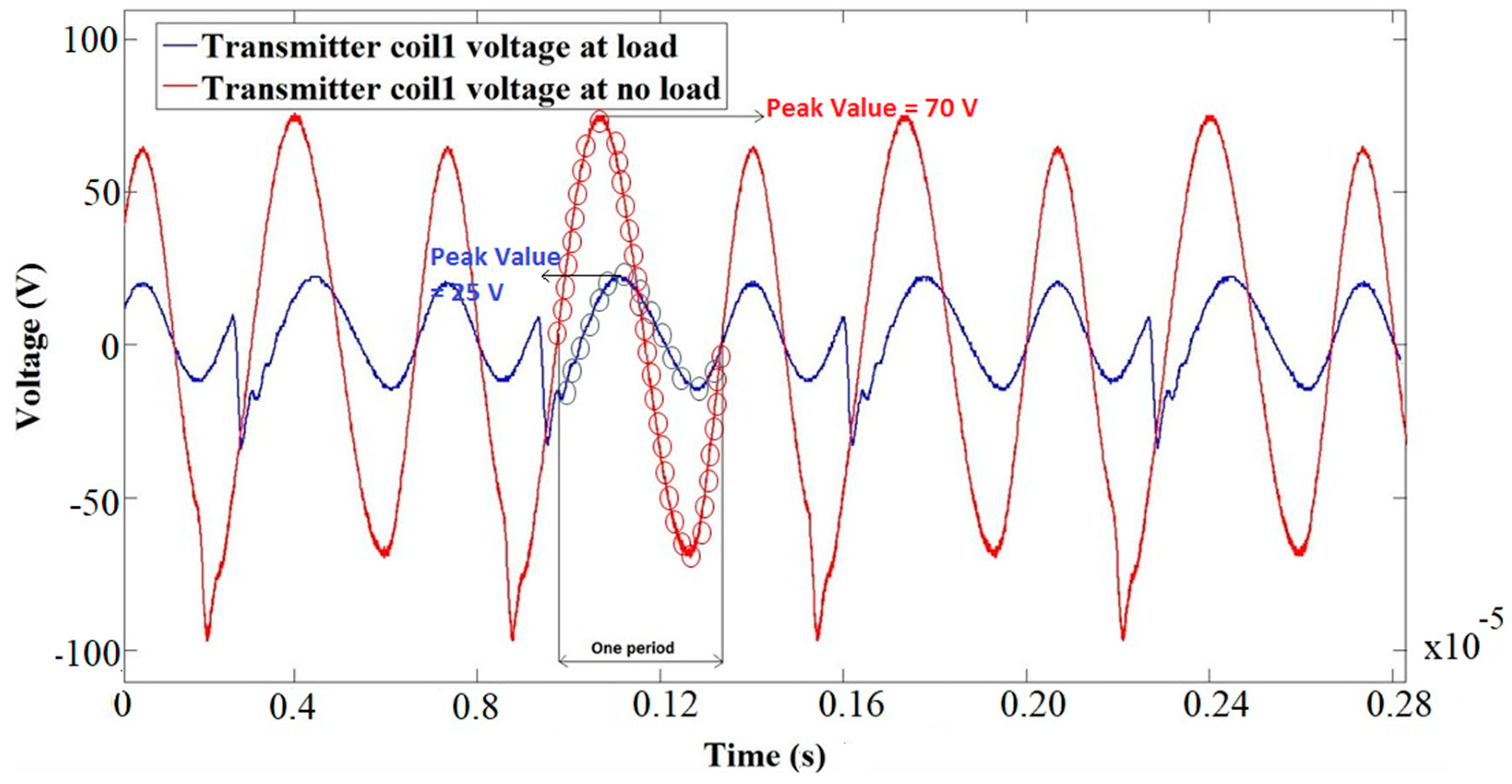
2.3.1. Signal Backscattering
Signal backscattering is a phenomenon basically used in wireless communication for RFID (radio-frequency identification). The transmitting side voltage tends to decrease by increasing the coupling between the transmitting and receiving coils. When the drone lands on the charging station, the
XY table starts the aligning process and, during the time of movement, the voltage at the transmitting side decreases rapidly. This change in voltage produces a natural backscattered signal. This backscattered signal at a very high sampling frequency of 84 MHz is continuously read by the ADC of the microcontroller.
Figure 6 shows the sampling process of the voltage signal during one period of time for aligned (transmitting coil voltage at load) and misaligned (transmitting coil voltage at no load) coils. Inside of the microcontroller, an envelope detection algorithm is used to detect the envelope of the backscattered signal. After the detection of an envelope, the peak value of the voltage signal is selected and this peak value is observed continuously to provide the information about aligned or misaligned coils. In the case of aligned coils, the peak value will be very low (almost 25 V;
Figure 6) and, in the case of misalignment, the peak value will be high (almost 70 V;
Figure 6). The hill climbing algorithm processes this voltage information data and finds the optimum solution by moving the
XY table in a specific direction and aligning the transmitting and receiving coils.
2.3.2. Hill Climbing Algorithm
Hill climbing is an optimization technique that is used to find an optimum solution to a computational problem. It starts off with a solution that is normally very poor compared to the optimal solution and then iteratively improves from there. It does this by generating other solutions which are better than the current solution. It repeats the process until it finds the optimal solution where it can no longer find any improvements.
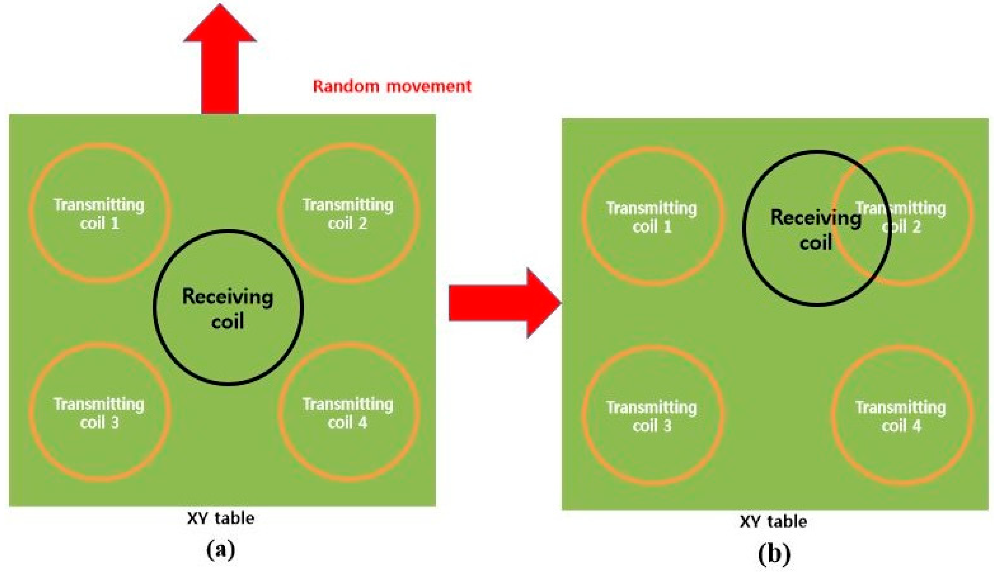
Generally, drones tend to land at any place upon the drone’s wireless battery charging station. That means the centroid of the receiving coil on the drone may not be aligned with any of the transmitting coils. In this case, transmitting coils are moved using the
XY table in an arbitrary direction to get closer to the receiving coil. By measuring terminal voltages of each transmitting coil, the controller can detect whether the receiving coil gets closer to one of the transmitting coils. This kind of arbitrary movement of the
XY table continues until it detects the decrease in terminal voltages of the transmitting coils, as shown in
Figure 7. When one transmitting coil, which corresponds to transmitting coil 2 in
Figure 7, is chosen, the hill climbing algorithm is activated to move the transmitting coil to the proper position where the voltage measured from that transmitting coil reaches its minimum.
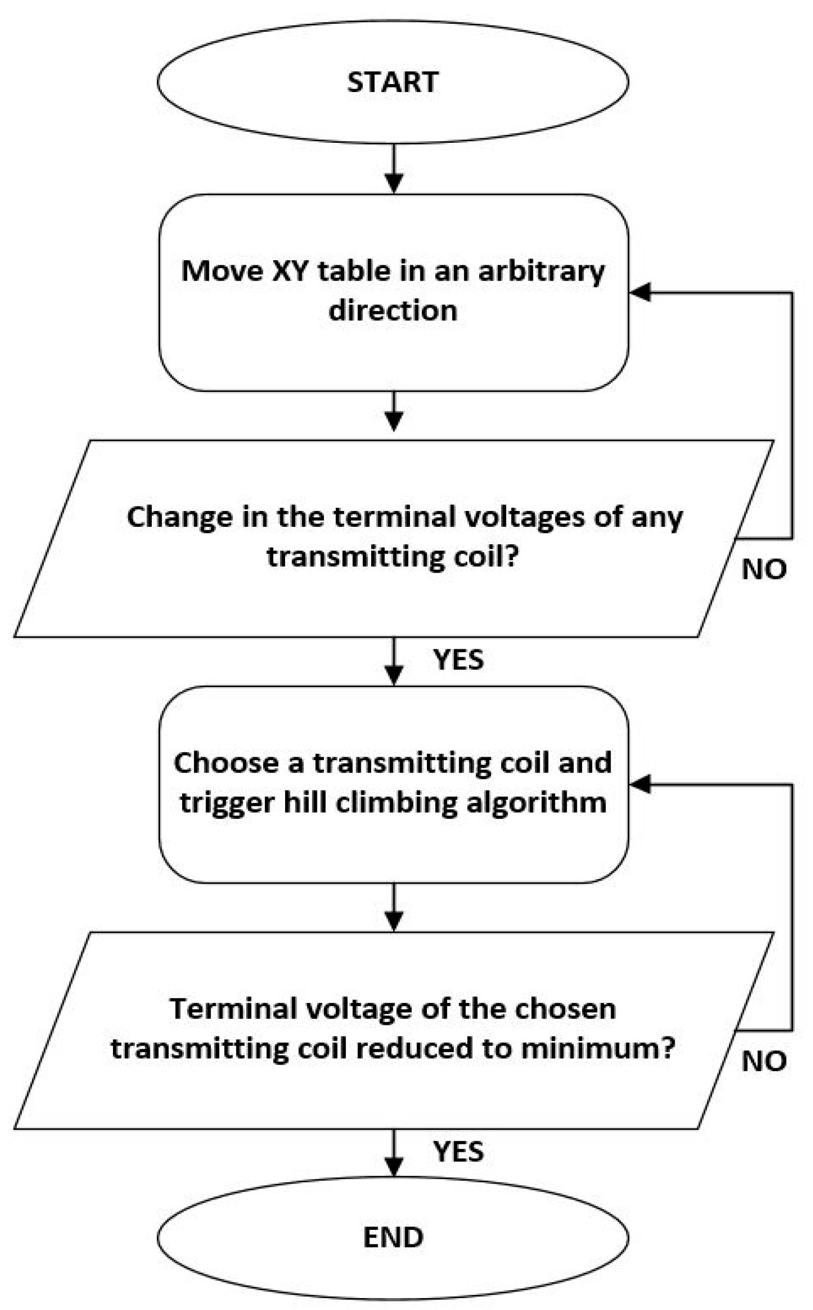
Figure 8 shows the overall flowchart of the proposed method.
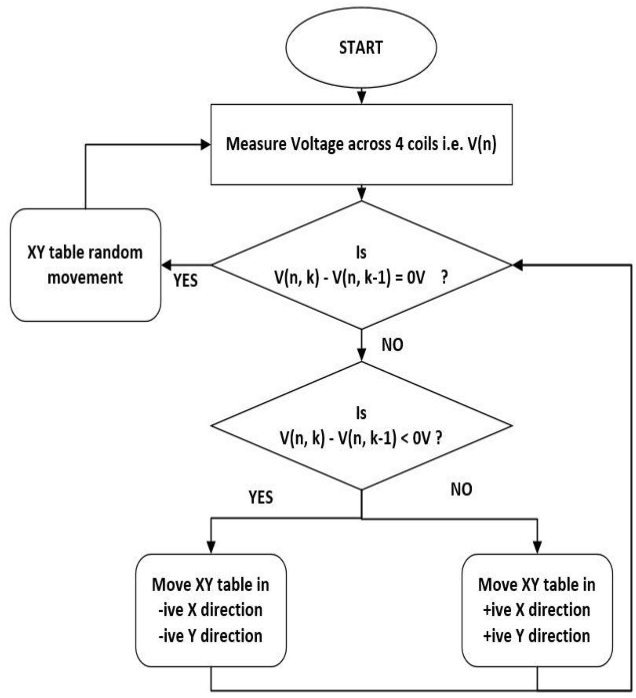
Figure 9 shows the flowchart of the hill climbing algorithm used in this system. Previously, authors tried to solve a different kinds of control problems using the hill climbing algorithm [
42,
43]. In this work, the hill climbing algorithm starts by sending the required PWM value to the stepper motor driver to move the
XY table. At the start, when there is no change in the voltage, i.e., the drone is not on the charging station, there is no movement and the voltage of the transmitting coil is constant. When the drone lands on the charging station, there is a change in the voltage value, and the voltage decreases in the presence of a drone with a receiving coil. The hill climbing algorithm is activated and one transmitting coil with the maximum change in the voltage value is selected. The current terminal voltage
of the selected coil is measured and compared with the previous measured voltage
. The minimum value is stored as
. After that, the controller sends the required PWM to move the
XY table to the position of the minimum value. This kind of process keeps repeating until it reaches the minimum voltage. In
Figure 9,
is the number of transmitting coils, and
is the number of the sample.
3. Explanation of the Test Bench
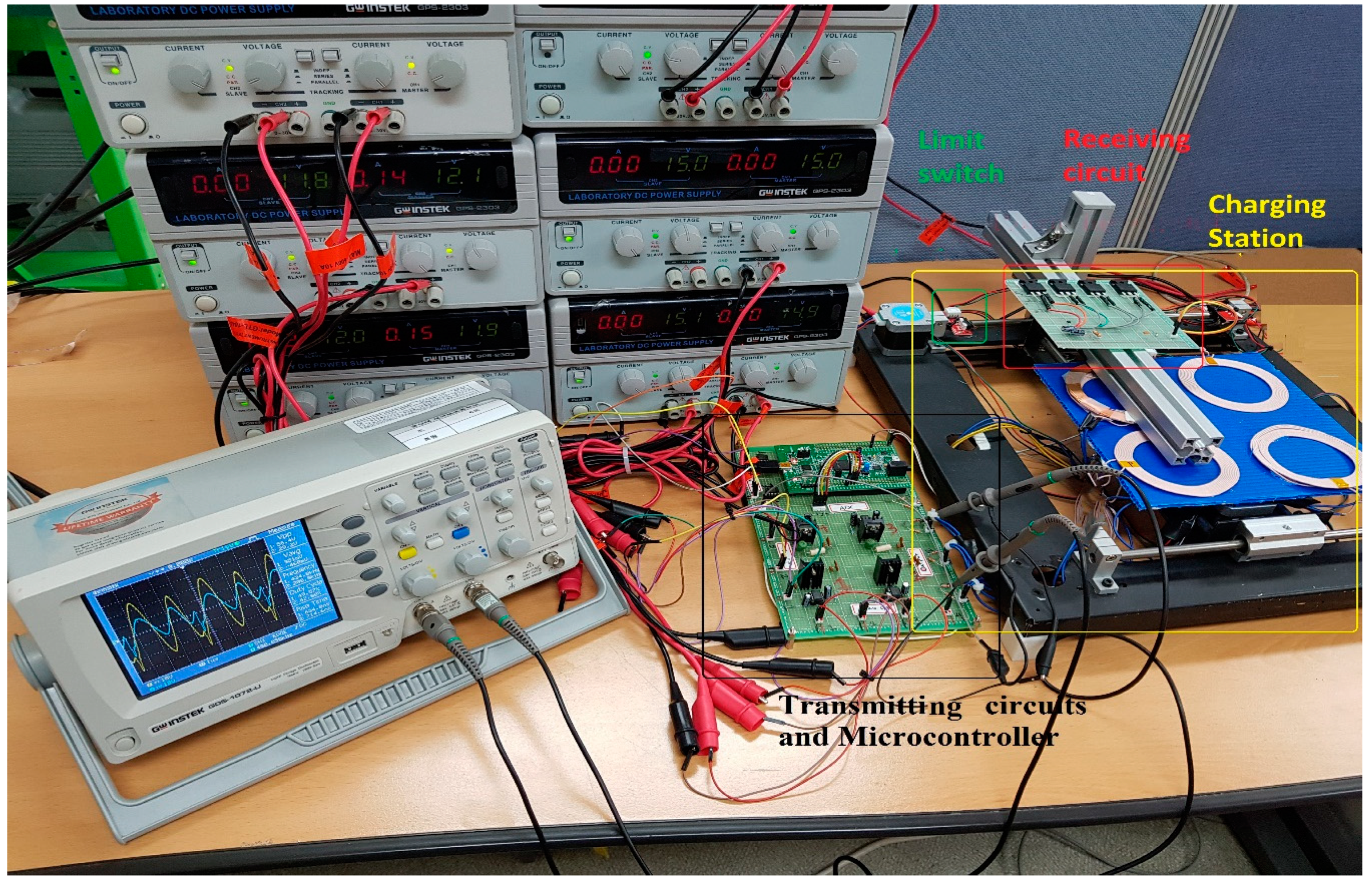
In order to verify the feasibility of the proposed algorithm, we made a test bench of a wireless power transmission and battery charging station for the drone. The developed test bench is shown in
Figure 10. The test bench was composed of four transmitting coils which are mounted on the four-way
XY table, one receiving coil connected to an electrical load, and a controller which performs the measurement and hill climbing algorithm.
3.1. Battery Charging Station
The battery charging station was built using an XY table. The XY table is used to move the transmitting coil array to the position where the centroid of the transmitting coil is aligned with the centroid of the receiving coil using the hill climbing algorithm. The dimensions of the XY table were . The main frame of the XY table was made of aluminum and the rectangular plate, where the coils are placed, was made of a plastic sheet with a thickness of 2.5 mm. Four transmitting coils were placed on top of the rectangular plate within the XY table and they were controlled by two stepper motors for positioning.
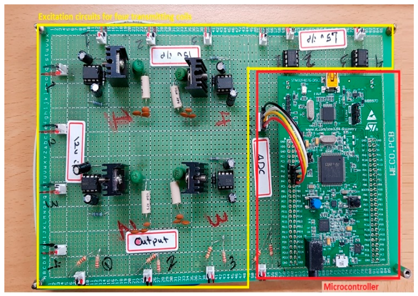
In this work, four excitation circuits for the four transmitting coils were developed. Each transmitting coil was connected to the excitation circuit. A gate voltage of 15 V and a supply voltage of 12 V were applied to the IRF510 metal-oxide-semiconductor field-effect transistor (MOSFET), and it was driven by a low-power 240 kHz clock signal, generated by the microcontroller. A voltage divider circuit was also built to decrease the output voltage into a voltage that was readable by the controller. Based on the proposed method and the equations presented in Reference [
40], the optimum values of the electrical components for the excitation circuits were calculated.
Table 1 shows the component values used in the excitation circuit, and
Figure 11 shows a closer view of the excitation circuits and controller.
3.2. Receiving Coil and Electric Load
When the drone lands on the battery charging station and the
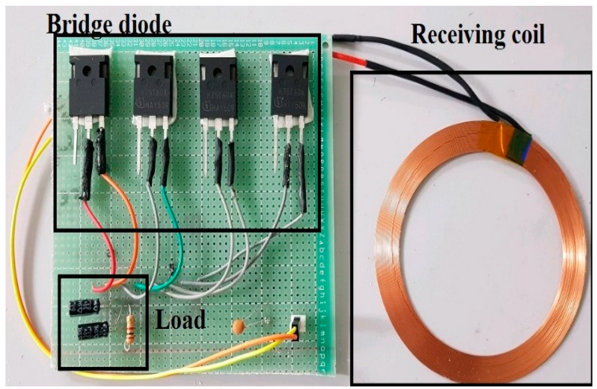
XY table starts moving the transmitting coil array to the proper position using the hill climbing algorithm, the transmitting coil starts to couple inductively with the receiving coil. This inductive coupling between the coils induces voltage in the receiving coil. The receiving coil is connected to the receiving circuit as shown in
Figure 3. The induced voltage at
is processed by a full-wave bridge rectifier to convert AC to DC. In this system, rectification is achieved via four insulated-gate bipolar transistors (IGBTs), designed to work on high-frequency AC input signals. The output voltage is obtained across the load resistor
.
Table 2 shows the component values used in the receiving circuit, and
Figure 12 shows a closer view of the receiving circuit and receiving coil.
3.3. Controller
In order to perform the control tasks, an STM32f4 discovery kit featuring a 32-bit ARM Cortex-M4 was used. It can generate up to a 168-MHz clock signal. It also supports ADC with 19 channels and 12-bit resolution. The controller was used to generate 240-kHz clock signals for the four excitation circuits and it read the terminal voltage of transmitting coils simultaneously.
When the drone lands on the battery charging station, the controller sends different PWM values to the two stepper motor drivers to move the XY table in random directions. At the same time, the controller keeps measuring the output voltage of the four transmitting coils. Once there is a drop in the voltage across one of the transmitting coils, the controller triggers the hill climbing algorithm and sends the required PWM to the stepper motor drivers until it measures the minimum voltage value where both the centroids of the transmitting and receiving coils are aligned; then, the hill climbing algorithm stops working, and the wireless power transmission begins until the drone is fully charged.
4. Experiments and Results
Several experiments are conducted with a test bench in order to verify the feasibility of the proposed scheme. The system was tested under different test scenarios depending on the drone landing position on the charging station. The receiving coil attached with load was placed at different positions on the charging station and the response of the system was observed. In one test scenario, the system was tested for the misalignment of
x = 100 mm and
y = 50 mm, whereas in other test scenarios, the misalignment was
x = 75 mm,
y = 30 mm and
x = 50 mm,
y = 10 mm. Regardless of the position of the receiving coil, the charging station was able to perfectly align the centroid of the transmitting and receiving coil with an accuracy of 98.8%.
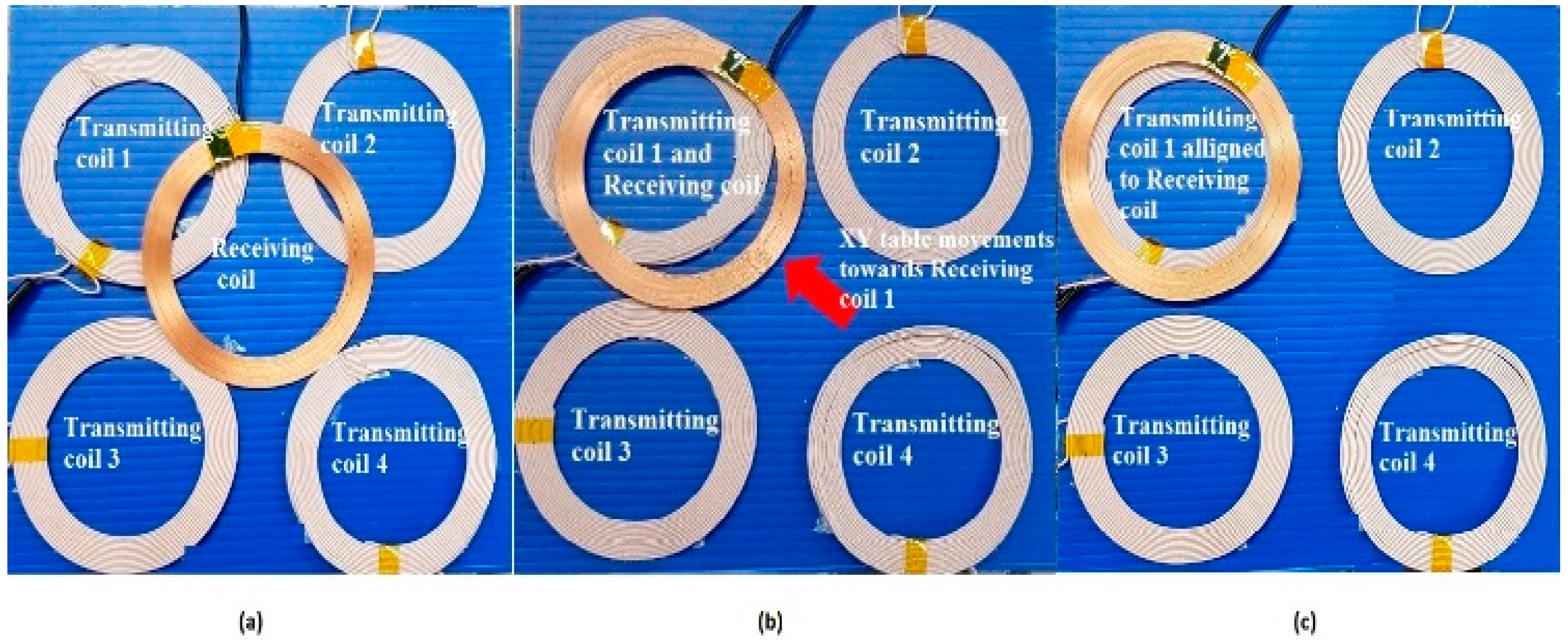
Figure 13 shows one of the test scenarios. Initially, we assumed that the receiving coil and four transmitting coils were positioned as shown in
Figure 13a. At the start, the
XY table was moved randomly until the receiving coil got closer to one of the four transmitting coils. During this process, the microcontroller kept measuring the four terminal voltages simultaneously. By detecting the voltage drop between all four transmitting coils, the microcontroller activated the hill climbing algorithm and the
XY table was moved to align the nearest transmitting coil with a receiving coil. The distance and position of the nearest transmitting coil were judged on the basis of the voltage drop. The closer the transmitting and receiving coil, the larger the voltage drop would be due to power transmission between the two coils. As shown in
Figure 13b,c, after the random movement of the
XY table, transmitting coil 1 was found as the nearest coil to the receiving coil. Then, the hill climbing algorithm was activated by the microcontroller and the
XY table moved to align transmitting coil 1 with the receiving coil.
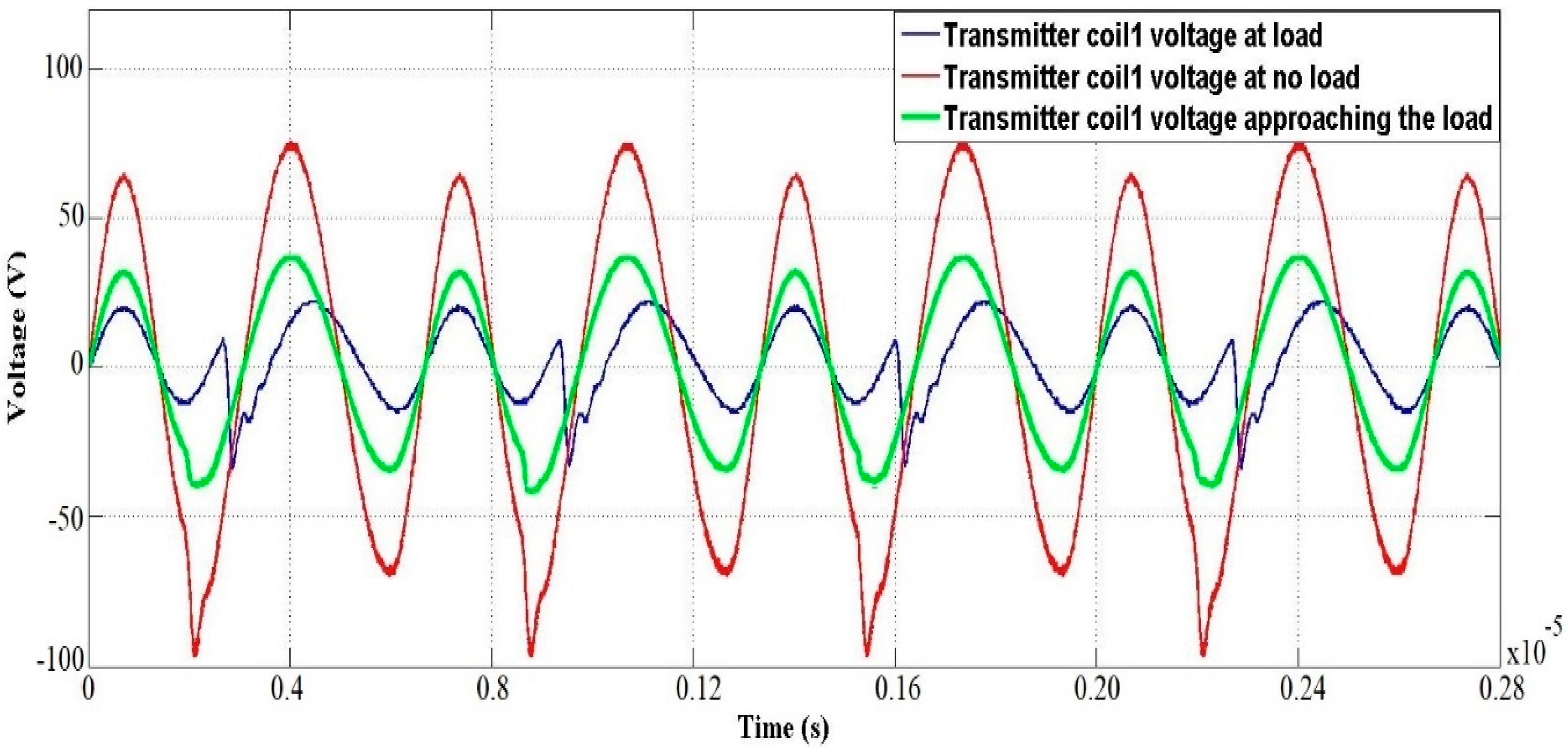
Figure 14 shows the recorded voltage waveforms for the scenario shown in
Figure 13. It can be seen clearly that the voltage of transmitting coil 1 decreased, red in the case of
Figure 13a, green in the case of
Figure 13b, and blue in in the case of
Figure 13c.
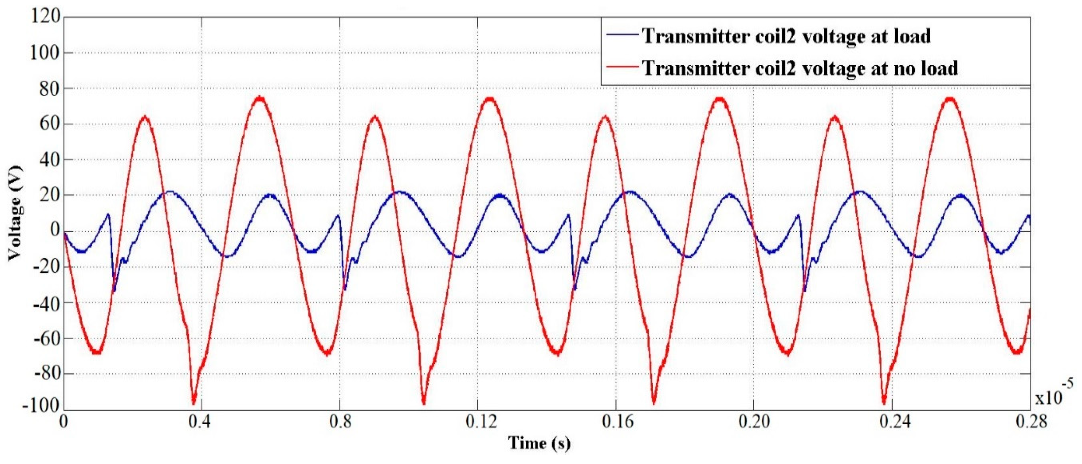
Figure 15 shows the voltage of other transmitting coils under load (wireless power transmission) and no load (normal) condition.
The system was designed for the transmission power of
.
Figure 16 shows the output power at the load resistance
under different test scenarios. The misalignment distance between the coils was changed and the load power
response was observed. The maximum load power
was measured to be 52 W, which gives an efficiency
of 85%. It can be observed in
Figure 16 that, as the distance of misalignment between the transmitting and receiving coils increased, the time taken by the charging station (
XY table) to properly align to the nearest possible coil also increased. In the case of a misalignment of
x = 100 mm,
y = 50 mm, it took almost 1.85 s to properly align the coils and transfer the power with designed efficiency. For misalignments of
x = 75 mm,
y = 30 mm and
x = 50 mm,
y = 10 mm, the time to align the coils was almost 1.58 s and 1.5 s, respectively. In a time ranging between 1.5 s and 1.9 s, the misalignment caused by the imperfect drone landing was eliminated and the power transmission was increased to the maximum power.
In order to validate the hill climbing algorithm, the data obtained from the practical test bench was used in MATLAB and simulations were carried out to assure the feasibility of the algorithm.
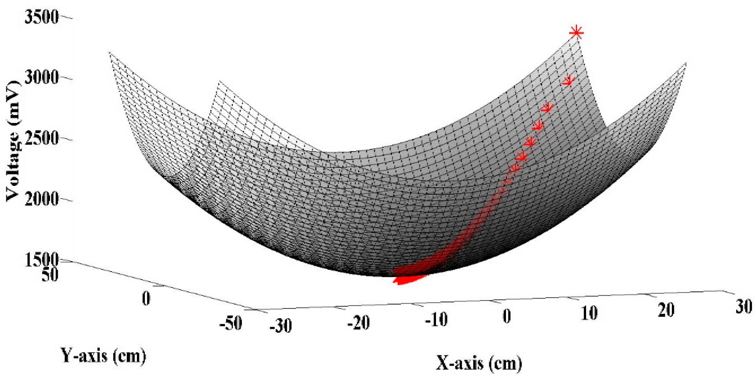
Figure 17 shows the trajectory of the
XY position for one transmitting coil in a three-dimensional space. It can be seen that, at the start, there is no voltage drop and the
XY table is moved to a random position. After two random movements, the position with the minimum possible voltage value is selected and, from that position, the hill climbing algorithm is activated and it keeps finding the best possible positions to align the transmitting and receiving coils until the minimum level is achieved. Once the minimum level is achieved, the transmitting and receiving coils are aligned properly and wireless power transmission starts with full efficiency.
The results obtained from the test bench shows that the proposed system is quite efficient in resolving the misalignment issue. The power transmission efficiency of 85% is reasonable for resonant inductive-based wireless power transmission, while also reducing the need for the implementation of complex tracking and landing algorithms for the drone. The time to align the centroid is also minimized due to the use of the hill climbing algorithm. The drone is free to land anywhere on charging station and, within a time of just 2 s, the centroid of the coils are aligned properly and the power transmission loss is mitigated.
Comparative Study
A comparative study of the proposed and previously presented solutions for drone imperfect landing (misalignment issues) is presented in this section. The system is compared with three solutions presented in Reference [
37,
38,
39].
In Reference [
37], the authors presented an approach based on the optimal design of the transmitting and receiving coils with the goal of becoming less sensitive to the misalignment of coils. The system was composed of a charging station with multiple arrays of primary or transmitting coils with a specifically designed secondary or receiving coil. The receiving coil was designed to perfectly fit in the landing skid of the drone. The authors proposed a transmitting coil overlapping scheme to entirely cover the charging area on the charging station. By calculating the impedance of the multiple transmitting coils and choosing the transmitting coil with maximum impedance, power transmission between the transmitting and receiving coils was achieved.
This system works well for a specific type of drone with some specific dimensions; however, if the size and dimension of the drone (physical size) changes, a whole new design of the charging station is required, and the transmitting coils will need to be readjusted again with some proper overlapping to cover the charging area properly.
On the other hand, our proposed system has non-overlapped multiple transmitting coils which can be moved in four directions. Furthermore, the proposed system utilizes the feature of backscattering which generally happens in wireless communication in order to identify the most closely coupled receiving coil among them. Even though the closely coupled receiving coil is detected, a further fine alignment of the centroids of the transmitting coil and the receiving coil is required to obtain efficient wireless power transmission by moving multiple transmitting coils. The proposed system is autonomous and totally free from the physical dimensions of the drone; it just needs to detect a receiving coil. This coil could be placed at any part of the drone where it can come in contact with any of the multiple transmitting coils placed on the charging station. The drone can land at any part of the charging station and, within just 1 to 2 s (min to max, depending on the distance of misalignment), the coils would be properly aligned with a strong coupling factor.
In Reference [
33], the impedance of the transmitting coils was monitored, which requires some current and voltage sensors to provide the measured value at every instance of charging operation. It increases the complexity of the charging station and requires more electronic components. On the other hand, in our case, the voltages of the transmitting coils are enough to ensure proper alignment between coils. Regarding power transfer capabilities and efficiency, in Reference [
37], the authors presented results based on the efficiency of wireless power transmission. The results showed that the efficiency of the system changed and decreased when there was misalignment between the coils. The efficiency met the minimum level requirement of 75% in all cases; however, upon misalignment, there was a reduction in efficiency from 88% (normal; no misalignment) to 83% (100-mm misalignment) and 78% (200-mm misalignment). In our system, the efficiency will always be the same (normal; no misalignment) because there is no misalignment and power transmission is done after ensuring this.
In Reference [
38], the authors presented a target detection technique based on image processing. After landing, the center of the coil was aligned with the transmitting coil using some specific color detection and image-processing scheme. The image-processing algorithm worked by taking the images using a drone camera and converted RGB color space to HSV color space. After applying some filters, the red color was detected and considered as a target.
There is always a chance of a failure in such a scheme contingent upon the outer environment and weather conditions; research work is still being pursued to improve such image-processing techniques. In our work, the drone is independent of such outer environmental uncertainties and the system works autonomously with the use of the hill climbing algorithm.
In Reference [
39], the authors presented a positioning system using a binary distance laser sensor and ultrasonic sensors. The system was composed of a charging station comprising a single transmitting coil and a drone equipped with a single receiving coil. The system worked by detecting the position of the receiving coil and aligning the transmitting coil with it for wireless power transmission. The positioning system took almost 5 s to detect and align with the receiving coil. Using sensors, the system complexity increases; it requires some specific areas for installation of the drone and the charging station. There is the possibility of errors in installing these sensors properly at the proper position so that the alignment between coils is always perfect. In our system, there is no physical sensor that needs to be installed on the drone or charging station. The time it takes to get the best possible solution is 1 to 2 s (min to max, depending on the distance of misalignment). The algorithm used in our system is much faster and much more robust, giving accurate results. Moreover, in Reference [
35], there is just a single transmitting coil used to transfer the power. In our case, the charging station is composed of multiple transmitting coils because using multiple transmitting coils gives the possibility of designing large charging stations for big drones. If the drone size is big, it will require more space for landing on the charging station. Using multiple transmitting coils decreases the time required to align the coils. Generally, the drone lands at any point on the charging station. In Reference [
35], it was made sure that the drone lands in the range of the sensors to initiate the alignment process; however, it would be almost impossible to initiate this process of alignment if the drone landed on the charging station and was out of range of the sensors. For this, in our charging station, multiple arrays of transmitting coils were installed to allow the drone to land freely anywhere on the charging station without the possibility of getting out of range.


