Abstract
The increasing number and complexity of cyber–physical systems in vehicles necessitate a rigorous approach to identifying functional safety and cybersecurity hazards during the concept phase of product development. This study establishes a systematic method for identifying safety and security requirements for E/E components in the automotive sector, utilizing the SysML language within the CAMEO environment. The method’s activities and work products are grounded in the ISO 26262:2018 and ISO/SAE 21434:2021 standards. Comprehensive requirements were defined for the method’s application environment and activities, including generic methods detailing the creation of work products. The method’s metamodel was developed using the MagicGrid framework and validated through an application example. Synergies between the two foundational standards were identified and integrated into the method. The solution generation was systematically described by detailing activities for result generation and the production of standard-compliant work products. To facilitate practical implementation, a method template in SysML was created, incorporating predefined stereotypes, relationships, and tables to streamline the application and enhance consistency.
Keywords:
safety; functional safety; security; cybersecurity; MBSE; method; automotive; ISO 26262; ISO 21434 1. Introduction
The integration of autonomous functions into vehicle concepts necessitates rigorous verification of functional safety to ensure compliance with approval and homologation requirements throughout the vehicle lifecycle. Over-the-air updates, increased interconnectivity of vehicle systems, and the sensitivity of data exchanged across diverse networks demand continuous monitoring and assessment of cybersecurity for each vehicle component [1]. The update strategies and digital functionalities of modern vehicles require a unified approach to maintaining functional safety and cybersecurity across all lifecycle phases, enabling coordinated development of vehicle components. The capability to add or modify functions post-deployment introduces a paradigm shift in design, emphasizing the necessity of early planning for potential future functionalities during the concept phase of vehicle development [2]. This requirement underscores the critical need for a method that facilitates the early identification of functional safety and cybersecurity. This study aims to establish a method for defining the comprehensive functional safety and cybersecurity requirements of electrical/electronic (E/E) vehicle components. The proposed method is designed to ensure compliance with relevant functional safety and cybersecurity standards. It will be fully implementable in the systems modeling language (SysML) and compatible with development environments utilizing model-based systems engineering (MBSE). The scope of the method is confined to the concept phase of the product lifecycle, ensuring precise and early-stage requirements identification.
2. State of the Art
2.1. Systems Engineering
Systems engineering (SE) aims to manage increased complexity and achieve a cross-disciplinary optimum within the financial and time constraints of a project. A strong emphasis is placed on user-centered development, enabled by focused requirement management and requirements engineering (RE). This focus on stakeholder requirements increases the efficiency of product development as the process is not slowed down by addressing irrelevant issues [3,4]. The early phase identification of requirements and design constraints and concepts speeds up and reduces the costs of development, as shown, for example, for hydrogen refueling stations in [5].
2.2. Model-Based Systems Engineering
The effective implementation of document-based systems engineering is hindered by the complexity and volume of information as data are dispersed across multiple documents. Model-based systems engineering (MBSE) addresses these limitations by using digital models instead of documents to store information [6]. MBSE establishes a framework for effective, consistent SE application within teams while being adaptable to specific tasks [7]. Unlike traditional SE, which relies on isolated documents, MBSE uses the model as the central foundation for development and communication, offering several advantages. By capturing all relevant development information directly in the model, MBSE improves stakeholder communication and knowledge retention. It enables the management and development of complex systems by constructing models with the necessary complexity [6]. MBSE employs a consistent language for describing problems and solutions and facilitating system validation and the verification of requirements [7]. Successful MBSE implementation requires the integration of a modeling language, modeling tool, and modeling approach [8]. The spread of MBSE-based modeling in the safety and security space is shown in Figure 1 (right) where the standard ISO 26262:2018 [9] uses the SysML language to define one of its terms, in this case for the definition of the term ITEM.
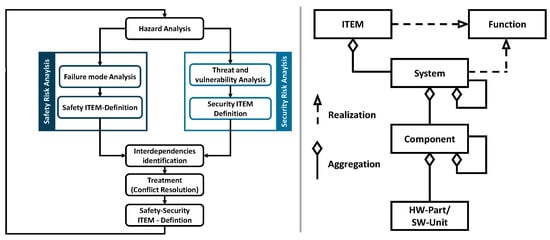
Figure 1.
A possible approach to integrating the safety and security risk analysis [10] (left); the definition of the term ITEM in ISO 26262:2018 using SysML nomenclature [9] (right).
2.3. Safety and Security Engineering
Safety and security aim to mitigate system risks but target distinct hazards. Safety addresses unintentional risks arising from system vulnerabilities, aiming to prevent accidents, and is categorized into product safety (focused on fault-free operation, including the safety of the intended functionality, SOTIF) and functional safety (addressing faults or malfunctions) [11]. Security mitigates intentional threats to E/E components of cyber–physical systems (CPS). It comprises functional security (protecting software from unauthorized access, modification, or suppression during development and operation) and information security (safeguarding data from unauthorized access) [11]. The foundational standards underlying the method to be developed are ISO 26262:2018 [9] and ISO/SAE 21434:2021 [12]. The identification of functional safety requirements for vehicle components is described in ISO 26262:2018 [9], while cybersecurity requirements are identified within the framework of ISO/SAE 21434 [12]. While the focus of this paper is on the cybersecurity framework developed specifically for the automotive industry, it is crucial to mention the General Data Protection Regulation (GDPR) [13] and the California Consumer Privacy Act (CCPA) [14] due to the fact that private data are collected during vehicle operation. Benyahya et al. point out that the application of GDPR is required and must be carried out together with the UN ECE R155 and R156 [15]. A possible GDPR-centered analysis for CAVs is shown by Benyahya et al. [16].
2.4. Interfaces of the Safety and Security Engineering
Safety and security often conflict, requiring prioritization strategies in CPS development. Success depends on aligning objectives, ensuring consistency, and addressing goal conflicts highlighted by ISO 26262:2018 [9]. However, ISO/SAE 21434 [12] lacks focus on safety interfaces, underscoring the need to synchronize safety and security lifecycles early in the design phase [17]. Safety and security analysis frameworks, such as HARA and TARA, share structural similarities, including fault and attack tree analyses, FMEAs, and verification techniques. Effective implementation requires a synchronized information flow, facilitated by integration with systems engineering (SE). This approach embeds control points in lifecycle models and ensures stakeholder inclusion [17]. A possible approach to integrating the safety and security activities is shown in Figure 1 (left).
2.5. Safety and Security Engineering in MBSE
The scientific literature deals with the integration of safety and security engineering into the MBSE environment from three perspectives: application examples, frameworks as well as approaches, and the implementation of individual safety/security-relevant frameworks (e.g., FMEA). The focus of this literature review is on analyzing methods, approaches, and frameworks. In the context of functional safety, Meyers et al. [18] describe the aSET approach, a high-level metamodel implemented in SysML from the concept phase to the HW/SW engineering phase. A profile implemented in UML for functional safety requirements based on ISO 26262:2018 [9] was developed by Frese et al. [19] for use in automated driver assistance systems. The implementation of parts of safety in MBSE as an interface between the document-based component model and the Matlab model for validation was described by Dybov et al. [20]. Safety–MBSE integration has been taken up by the Object Management Group (OMG) with the aim of supplementing it with safety applications from the perspective of the SysML environment. The OMG’s safety specification for SysML consists of a metamodel that supplements SysML with the necessary stereotypes and enables FTA, FMEA frameworks, and the implementation of HARA [21,22].
Metamodel-based approaches to integrating standards-based processes with MBSE solutions are also available in cybersecurity. Based on a template and SysML stereotypes, Mazeika et al. [23] have shown how a cybersecurity concept can be modeled in SysML. The cybersecurity process from requirements to solutions has been adapted by Larsen et al. [24] as a process model for MBSE, focusing on the identification of security requirements in the early stages of development in the context of aerospace. Oates et al. [25] describe the translation of cybersecurity threats into SysML with the security-aware systems engineering approach whereby the aim is the early integration of the threats into the SysML model of the product. The HEAVENS approach describes the security process from the TARA to the definition of the security requirements. The HEAVENS approach was implemented together with the processes of ISO 26262:2018 by Häring et al. [26] using the IBM Rhapsody framework in SysML, which enables the implementation of the safety and security analysis from the ITEM definition to the technical safety concept. Stakeholder information was transferred to the MBSE context by Japs et al. [27] and used as the basis for the hazard analysis of safety-relevant cybersecurity hazards. The relevance of integrating MBSE and safety/security is also shown by the fact that the manufacturer of one of the most prominently used tools for MBSE, Dassault Systems, released packages that contain the modeling elements for certain parts of the base standards [28,29].
The analysis of the scientific literature shows that the implementation of the base standards in an MBSE context is widespread. The safety and security processes, conforming to the base standards, were carried out by Häring et al. [26]. The general focus of the scientific work in the subject area analyzed is on the implementation of the base standards or frameworks, such as TARA, as metamodels or templates for carrying out safety and security activities. Outside the focus of the publications is the integration of safety and security management into the method, the possible tailoring approaches depending on the use cases of the method, the detailed modeling of the individual activities from the perspective of method and information flow, and the modeling of the application environment of the method as a prerequisite for conformity with the base standards.
2.6. Research Questions
Based on the analysis of the current literature in Chapter 2.5, the following aims are defined for this paper:
Question 1: Implement a method to identify safety and security requirements for the concept phase of product development utilizing the capabilities of the MBSE framework.
Question 2: Integrate steps into the method, which have not been, till now, the focus of research, such as safety and security management and the detailed (meta)modeling of activities prescribed in the base standards.
Question 3: Integrate the safety and security activities as much as possible to utilize the synergies and duplicities of the activities within the MBSE framework.
3. Materials and Concepts
3.1. Software Tool
The modeling language used in this paper, SysML, is a graphical language. The information stored in the model is represented via a group of views or diagrams [26]. CAMEO SYSTEMS MODELER (CSM, Version: NoMagic 2022x Golden), the software in which the modeling is carried out, is a cross-platform, collaborative modeling tool from Dassault Systems that enables integration with a variety of other engineering tools from Dassault Systems. The metamodel of the method was created based on the CAMEO internal modeling framework MagicGrid. However, the framework must be adapted to the modeling of a methodology. This framework can be used for the entire SE lifecycle because the grid model is best suited for representing the various aspects and views of a methodology and because the master thesis is carried out in the native system of the MagicGrid methodology, in CAMEO [30].
3.2. Information Management of the Method
The methodology is based on the evaluation of the ISO 26262:2018 [9] and ISO/SAE 21434:2021 [12] standards, which, in this paper, are referred to as base standards. The method uses two specific sources of external information: “ENISA: Good Practices for smart cars” [31] and “UN ECE R 155” [32], which contain the checklists for cybersecurity asset identification and cybersecurity threats and mitigation approaches. Input data for the safety and security activities, as outlined in Table 1, is categorized into internal and external information. Internal data pertain to the organization, project, or ITEM under analysis, while external data include supplementary standards, guidelines, or checklists supporting specific activities of the method. These are further complemented by frameworks such as “HazOp”.

Table 1.
Information management of the method.
3.3. Development Strategy
The development of the method is conducted by adapting the V-Model (Figure 2). Before the principal development, the concept of the method is outlined; this is accomplished by analyzing relevant stakeholders and their views. The views and the previously acquired general knowledge are the basis for the definition of the requirements and relevant measures of effectiveness. Based on the analysis of relevant standards, the structure of the method is defined, which is then broken down to its elements. The elements are then implemented in CAMEO using SysML and integrated according to the MagicGrid framework.
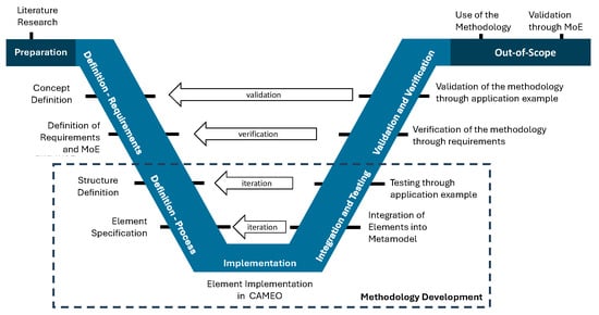
Figure 2.
Development of the method.
3.4. Generic Activities
The foundational standards define the safety and security frameworks as sequential activities with specified input and output information but do not provide detailed procedures for execution. During the analysis of the base standards, six generic activities were implemented, to be assigned to each activity of the method, enabling a generic description of each task. The DETERMINE generic activity uses predefined checklists or formulas to generate output without creative input. The DEFINE generic activity and DEVELOP generic activity require high creativity: the DEFINE generic activity applies concepts such as brainstorming, while the DEVELOP generic activity adapts generic approaches to the project context for tailored solutions. The ALLOCATE generic activity aligns existing information, while the ASSEMBLE generic activity both aligns and generates target information. The CATEGORIZE generic activity segments input into comprehensive, context-specific values. An overview of these generic activities is provided in Table A1.
3.5. Tailoring
The term “Tailoring” refers to the adaptation of frameworks prescribed by standards or guidelines to suit the specific conditions of a project. During safety-tailoring, the requirements of ISO 26262:2018 [9] must be observed, while during security-tailoring, the requirements of ISO/SAE 21434:2021 [12], along with the demands of the safety and security frameworks and the environmental requirements of the method, must be taken into account, as shown in Table A2, Table A3, Table A4 and Table A5. The goal of tailoring is to define a process that complies with standards at every step, meets process requirements, and can be executed within the constraints of the existing environment.
3.6. Identification of Synergies
Identifying synergies between safety and security frameworks optimizes time, resources, and collaboration among teams. These synergies, detailed in Table 2, are identified by comparing activities and work products. Synergies exist in preliminary safety/security management and ITEM definition. Preliminary management benefits from shared execution environments and pooled resources, enabling efficient scheduling. However, separate work products are required to comply with standards and facilitate independent regulatory submissions. A joint ITEM definition is viable as foundational standards align in this area, though ISO 26262:2018 [9] demands more detailed ITEM environment documentation than ISO 21434:2021 [12]. HARA focuses on ITEM functions, while TARA addresses cybersecurity assets, preventing alignment and synergy. Concept development shares approaches in requirements engineering and hazard/threat evaluation but lacks significant synergies due to differing inputs from TARA and HARA and their distinct scopes.
Table 2.
Synergies between the safety and security processes.
4. Development of the Method
The modeled content, shown in Figure 3, showcases the artifacts of the method development, documented in a tailored version of the MagicGrid framework, and the details for the tailoring of the model are described in Table A6.
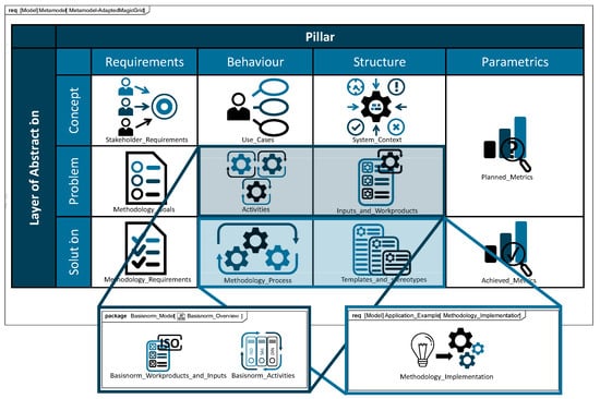
Figure 3.
Created models (implementation in SysML, based on the MBSE MagicGrid [25]).
4.1. Stakeholder Viewpoints
Based on the project goals, the stakeholders, listed in Table 3, were identified as relevant from the perspective of the method. The successful development of the method is based on the identification of objective requirements that are expressed by all stakeholders of the project. Three stakeholder groups were identified as part of the method: project engineering (responsible for the course of the project and communication, and exchange with external partners), management (responsible for costs, infrastructure, organizational culture, and acquisition), and safety and security engineering (users of the method).
Table 3.
Identification of synergies between ISO 26262:2018 [9] and ISO 21434:2021 [11].
4.2. Use Cases
Based on the analysis of the base standards and taking the stakeholder viewpoints and the project scope into consideration, the use cases were identified. The identified use cases can be divided into four categories: Project Management, Defining the ITEM, Analyzing the Risk, and the Concept of Risk Mitigation. The use cases were assigned to the stakeholders derived from the safety and security engineering stakeholder group. In order to anchor conformity with the standards early on in the development of the method, the three phases including project management, the safety- and security relevant aspects of an ITEM, and the project objective were modeled separately as included use cases.
4.3. Method Environment
The analysis of the base standards resulted in the identification of the requirements for the method environment that must be met to achieve standard compliance, as described in Table A7. The base standards define specific requirements for the management of safety and security at the organizational level (e.g., culture, management, and infrastructure, including competences), but the implementation of permanent security activities must be also demonstrated for the security framework. Permanent cybersecurity activities are responsible for monitoring the cyber(security) environment of the ITEM and potential threats.
4.4. Measurements of Effectiveness
The requirements derived from the project requirements are supplemented by measures of effectiveness (MoEs) in the evaluation of the method. MoEs are parameters that are measurable, which can only be determined by using the method in its application environment. The MoEs that were identified are average education time required by employees to utilize the method, comparative rate of successful approvals by the relevant authority, average timesaving compared to projects not using the method, adoption rate by employees, number and severity of incidents that occurred compared to other approaches, and rate of unsuccessful attempts of using the method.
4.5. Requirements of the Method
The requirements of the method (Table 4) are derived from the stakeholder viewpoints (Table 3). The requirements of the method specify and formalize the intended scope and objective of the development of the method further.
Table 4.
Requirements of the method.
4.6. Activities
The use cases of the method were further specified as activities, which consist of chapters, subchapters, requirements, and work products which were kept during the tailoring frameworks of the base standards, documented in Table A8, Table A9, Table A10 and Table A11.
The main activities and support activities of the method are carried out iteratively. This iterative approach is shown in the parallelization of the activities (Figure 4—top). The activities model forms the spine of the method as it summarizes all the activities required to meet the normative requirements. Activities possess two types of input information: work products created in previous steps and external information (Figure 4—bottom). The output information is arranged on the right-hand side of the activities and contains the work products created during the execution of the activity.
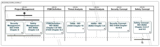
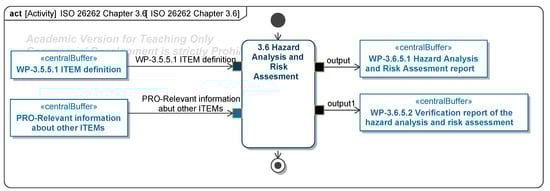
Figure 4.
An overview of activity chapters (implementation in SysML) (top); Examples of the model of activity components (implementation in SysML) (bottom) [9].
4.7. Work Products
4.8. Requirements for the Application of the Method
Based on the requirements of the method (Table 4) and the requirements for the method environment (Table A7), the requirements for the application of the method are derived. The requirements for the application of the method summarize and define the conditions under which the method can be used (Table A14).
4.9. Flowchart of the Method
The procedure for implementing the method can be derived from the analysis of the base standards and the tailoring of the activities (Figure A1). Starting from the overview of the method (Figure 5), each chapter is further subdivided and specified in a diagram assigned to it until each activity of the method is modeled (Figure 6). An activity has three types of input information: DATA—information that is the basis for performing the procedure element; STEREOTYPES—the stereotypes used to model the outcome of the procedure; and METHOD—one of the methods specified in Table A1 that describes how the activity must be created. The method procedure refers to the initial processing of the activities; the iterative approach to processing has already been illustrated in the activity diagram, in which the method can only be completed by creating each defined work product.
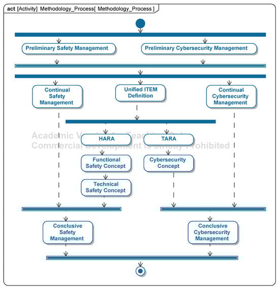
Figure 5.
An overview of the method as a flowchart (implementation in SysML).
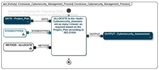
Figure 6.
An example of an activity of the method (implementation in SysML).
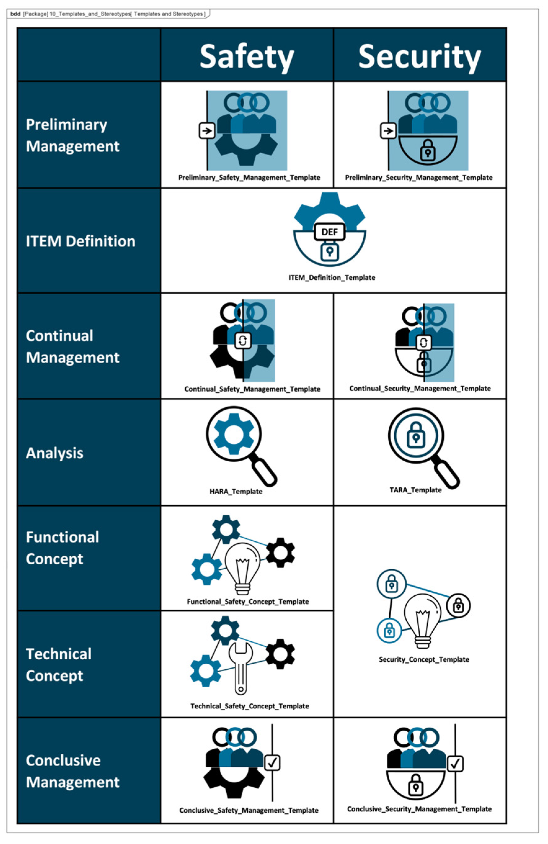
4.10. Template of the Method
The methods template was created based on the analysis of the base standards and the procedures defined in Section 4.9. The method template contains all the elements, stereotypes, and relations required to fully implement the safety and security frameworks within the SysML language. The overview of the template of the method is shown in Figure A1.
4.11. Achieved Measures of Effectiveness
The MoEs defined in Section 4.4 (Measurements of Effectiveness) are assigned target values during the adaptation of the method to its specific application environment. The target values of the MoEs must be measurable, realistic, and objective. The validation of the MoEs is outside the scope of this paper and must always be carried out for the specific application environment. Achieving the target values of the MoEs depends on factors such as workshop quality, infrastructure, project type, and the type of product under investigation.
5. Use Case
The use case serves as an example of how to model a system’s safety and security characteristics. Its goal is not to provide a concrete example of a fully modeled vehicle E/E system.
5.1. Preliminary Management
The method begins with preliminary safety and security management where work products and their tailoring status are documented. Each work product’s inclusion or exclusion must be justified via a tailoring rationale. Activities responsible for generating these work products are specified, detailing objectives, responsibilities, required resources, and supporting tasks in compliance with normative standards. Supporting activities, as mandated by ISO 26262:2018 [9], such as verification procedures and ASIL (automotive safety integrity level) decomposition, must be defined for the safety framework. A schedule for developing safety and security work products is then established, often visualized using Gantt charts in the CAMEO environment, with time units represented as “Timeframe Elements”. The method defines project goals and scope to address key questions and specify required requirements and concepts. Goals clarify the intended use, while the scope identifies project limitations, areas excluded, and the necessary detail level for work products. Documenting goals and scope contextualizes project decisions and ensures clarity, often represented as requirements diagrams, subdivided into safety and security diagrams if needed. The diagrams of the model are shown in Figure A2, Figure A3, Figure A4 and Figure A5.
5.2. Unified ITEM Definition
The ITEM definition consolidates all available information to ensure a shared understanding among stakeholders. It serves both safety and security frameworks, with ISO 26262:2018 [9] requiring a detailed description of the ITEM’s environment, functions, and impact on the vehicle. The analysis of ITEM boundaries and interfaces must document internal elements and shared interfaces with external ITEMs. Both black-box and grey-box models are required to specify interface types (e.g., mechanical, logical, electrical), varying by project. The ITEM architecture, modeled as a white-box view, describes its elements and interfaces. This may include decentralized or external elements for clarity. Functions are modeled as requirement sets detailing ideal behavior and limitations and as process models capturing activity sequences. Use cases define the ITEM’s purposes and interactions, further refined with additional requirements. The ITEM environment encompasses operational conditions, including climate, infrastructure, digital connectivity, and repair access. Lifecycle requirements address the ITEM’s needs across phases: development/testing, manufacturing, operation, service, and decommissioning. While focused on early phases, understanding later stages aids in tailoring safety and security requirements. The diagrams of the model are shown in Figure A6, Figure A7 and Figure A8.
5.3. Hazard Analysis and Risk Assessment
In the Hazard Analysis and Risk Assessment (HARA), hazard scenarios are identified and assigned an ASIL (automotive safety integrity level) rating, which determines safety goals to mitigate risks. HARA begins with defining operational situations relevant to the ITEM, characterized by attributes, categories, and an exposure value indicating operational frequency. Malfunctions are identified via a HazOp procedure, categorizing failures in functionality. Accident scenarios arise from malfunctions occurring in specific operational situations, with each scenario assigned a controllability rating to assess manageability by the driver. From accident scenarios, hazardous events are identified, representing situations that may lead to accidents. Hazards—conditions or behaviors arising from malfunctions—are documented and linked to hazardous events using tailored HazOp or FMEA frameworks. Multiple hazards may correspond to a single hazardous event and vice versa. Effects of hazardous events are defined at both ITEM and vehicle levels, linked to specific elements, and assigned a severity rating. Ratings range from severe (e.g., collisions) to minor (e.g., slow driving). Severity, controllability, and exposure ratings collectively determine ASIL values. Each hazardous event requires at least one safety goal, aimed at reducing associated risks to acceptable levels. The diagrams of the model are shown in Figure A9, Figure A10, Figure A11, Figure A12, Figure A13 and Figure A14.
5.4. Threat Analysis and Risk Assessment
The Threat Analysis and Risk Assessment (TARA) identifies, evaluates, and assigns risk treatment decisions to attack scenarios affecting the ITEM. These decisions define how risks are managed in the security concept. Assets, the cybersecurity-relevant components of the ITEM, are assigned to ITEM elements and identified using the ENISA checklist [27]. Multiple assets, such as software, status, data, and configurations, may correspond to a single element. Damage scenarios, linked to specific assets and cybersecurity properties (availability, integrity, confidentiality), describe potential harm and vehicle impact. Unclear scenarios are divided for precise property assignment. The case study iteratively developed damage scenarios by analyzing asset vulnerabilities across these properties. Threat scenarios outline potential threats to ITEM assets, identified via the UN ECE R 155 checklist [28]. Each scenario is associated with a cybersecurity property, and ambiguous scenarios are subdivided as necessary. An impact Rating assesses each damage scenario’s effect on safety, financial, operational, and privacy (SFOP) attributes, with a rating assigned for each category. Attack paths detail attack steps for ITEM assets. Each threat scenario is linked to attack approaches, which are further divided into steps. In the case study, attack paths traced vulnerabilities to ITEM boundaries. Non-ITEM system attacks are also considered in the security concept. Attack feasibility ratings evaluate the practicality of attack approaches based on factors such as time for vulnerability identification, required resources, available knowledge, and execution windows. Risk ratings are calculated for each attack approach using impact and feasibility ratings. Based on these ratings, risk treatment decisions determine whether risks are acceptable, redistributed, or mitigated in the security concept. Risk treatment decisions are tabulated for attack approaches and threat scenarios. If any decision mandates risk reduction, the corresponding threat scenario requires mitigation. These decisions form the basis for security concept requirements. The diagrams of the model are shown in Figure A15, Figure A16, Figure A17, Figure A18, Figure A19, Figure A20, Figure A21, Figure A22 and Figure A23.
5.5. Functional Safety Concept
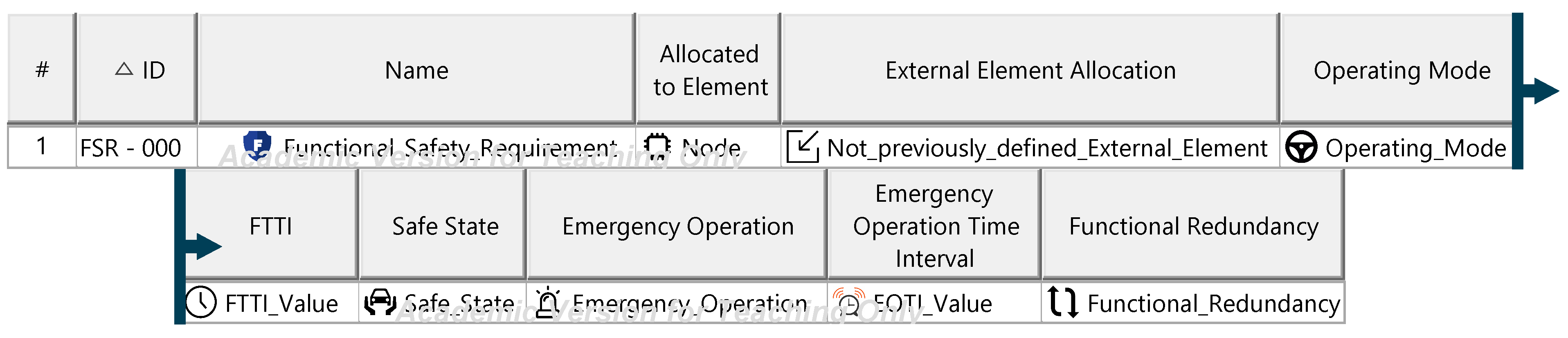
The functional safety concept aggregates functional safety requirements, defining the measures needed to reduce ITEM risks to acceptable levels. It serves as the foundation for specifying ITEM functions via technical safety requirements within the technical safety concept. Functional safety requirements, derived from safety goals, are implemented using ISO 26262:2018 [9] strategies such as fault prevention, detection, or driver warnings. Each requirement is assigned a single safety strategy and describes the functions necessary to achieve safety goals without specifying technical solutions. Requirements are allocated to ITEM elements or external vehicle components. Further specification uses predefined categories, with updates required for values determined in later development phases. The functional safety concept collectively underpins the technical safety concept. The diagrams of the model are shown in Figure A24 and Figure A25.
5.6. Technical Safety Concept
The technical safety concept comprises all technical safety requirements, defining the system-level implementation of functional safety requirements and guiding hardware (HW) and software (SW) development. Technical safety requirements are derived from functional safety requirements, providing specific technical solutions. Each functional safety requirement must have at least one corresponding technical safety requirement, which should be subdivided if it applies to multiple functional safety requirements or relates specifically to HW or SW to ensure traceability. These requirements must be detailed using predefined categories, with updates for values determined in later development phases, and must be assignable to specific ITEM functions. The diagrams of the model are shown in Figure A26 and Figure A27.
5.7. Security Concept
The security concept defines the cybersecurity requirements necessary to reduce the ITEM’s vulnerability to cyberattacks, forming the basis for its technical specification and lifecycle development. For threat scenarios with acceptable risks, cybersecurity claims document the justification. Each threat scenario is assigned a cybersecurity assurance level (CAL), determined by evaluating the attack impact (severity) and attack vector (attack approach). The CAL dictates the evidence required for validating ITEM security. For threat scenarios requiring risk reduction, cybersecurity goals are defined, specifying the target state to achieve acceptable risk. Each goal is supported by at least one cybersecurity requirement, detailing measures for prevention, detection, and monitoring. These requirements must be linked to ITEM elements and include operational environment requirements specifying conditions for fulfillment. The diagrams of the model are shown in Figure A28, Figure A29 and Figure A30.
5.8. Continual Management
The continual management of safety and security activities involves the documentation of the generated work products within the safety case and security case. Upon completion of an activity, all resulting work products must be added to the respective safety or security case. The safety or security cases do not have predefined templates.
5.9. Conclusive Management
As part of conclusive management, the work products required for verifying the safety and security status of the ITEM are compiled. The method’s documentation is submitted during the safety audit, while the work products are provided to the regulatory authority or the independent safety assessor (ISA) as part of the safety confirmation review. The cybersecurity assessment consolidates the work products from the cybersecurity framework.
6. Results
This study presents a novel method that integrates safety, security, and their management aspects within a comprehensive model-based systems engineering (MBSE) method for automotive electrical and electronic (E/E) systems. To the best of our knowledge, this is the first study to consolidate these three critical domains into a unified and structured method. Unlike previous research trends, which have primarily addressed safety and security separately, this study introduces a method for the generation of work products as required by relevant standards. The proposed method defines six generic activities that algorithmize the process of identifying and implementing solutions, thereby providing a systematic and repeatable method for addressing safety and security challenges in automotive E/E systems. A significant outcome of this research is the establishment of an MBSE method that incorporates specifically defined stereotypes and relationships. This structured approach enhances traceability and facilitates collaboration throughout the development lifecycle by providing a formalized means of linking requirements, models, and design elements. The structured representation supports seamless communication among stakeholders and ensures compliance with regulatory requirements. Furthermore, the study includes an in-depth analysis of normative requirements and their systematic translation into a step-by-step process model. This method formalizes the transformation of abstract regulatory mandates into practical, executable engineering workflows, thereby bridging the gap between compliance requirements and their implementation in development processes.
7. Discussion
Implementing the method in SysML enhances comprehension by reducing textual explanations and minimizing misunderstandings. Unlike base standards, which define work products and their requirements, the method provides detailed guidelines on activity order, required information, and interconnections, supporting creative problem-solving while leaving solution identification to users. Safety and security framework synergies were identified, particularly in project management and ITEM definition. Common templates and activities may reduce processing time, but the extent is project-dependent and requires validation. Incorporating technical safety requirements (TSRs) ensures functional safety requirements (FSRs) are achievable. TSRs also aid in developing security requirements by prescribing connections or defining new cybersecurity assets. TSRs guide sub-discipline development but must be documented to clarify their flexibility and prevent misinterpretation as fixed constraints. Safety and security requirements must be evaluated to address conflicts, such as safety’s preference for redundant controls versus cybersecurity’s aim to minimize assets at risk. Integrated processing resolves such conflicts, but awareness of these trade-offs is essential throughout the method. Completeness of requirements is guided by standards and verified through work product reviews, though subjective assessment by project leaders remains necessary. Internal reviews ensure safety and security aspects are fully addressed. Unlike approaches reviewed in the literature, this method includes a management phase, enabling early capacity, information, and evidence planning for standard compliance, thus improving resource allocation for the concept phase. A unified ITEM definition prevents redundant activities, ensures consistent asset and function assignment, and maintains coherence in integrated safety and security concepts, avoiding the misalignment caused by separate ITEM definitions.
The application of this method is limited to the scope of its base documents, that is, the E/E architecture development of vehicles. Furthermore, its focus lies solely on the concept phase of the development process, finishing with the requirement definition for the system concept. The developed system, if accomplished according to the method, is compliant with the base documents; however, country-specific requirements are not taken into account. The method also presupposes the common responsibility and availability of data for both the development of functional safety and the cybersecurity concept of the system. While the combined implementation of the safety and security activities in SysML at this scope is a novel concept, during further studies its real-life applicability must be tested “in-the-field”. While the general applicability of the method has been tested on a basic model, the method must be verified on systems with real-life complexity. Possible “in-the-field” validation or verification of the method would entail its use within the development process of an actual automotive E/E component, ideally within multiple development processes, to determine its averaged performance compared to the classical, separate approach.
8. Conclusions
This paper defines a method for identifying safety and security requirements for E/E components in the automotive sector, developed in SysML using the CAMEO environment. Unlike existing approaches that focus on specific frameworks or approaches of base standards, this method integrates the entire safety and security framework of the concept phase, emphasizing standard conformity and a structured approach to creating work products. The method aims to simplify the implementation by detailing process steps, reducing the amount of double work and offering a supporting method for interpreting the tasks described in the base standards. Addressing the entire concept phase enables leveraging synergies between safety and security analyses, reducing the number of required work products, due to eliminating duplicities. Early identification of safety and security requirements facilitates their integration into the development process. While research primarily focuses on engineering phases (e.g., ITEM definition, HARA, TARA, concepts), this method incorporates management aspects, essential for standard compliance. Effective project management, which has not been integrated in the reviewed frameworks, aims to support the successful completion of activities. The method’s requirements, activities, and work products were derived from base standards and modeled as a SysML metamodel. Expanding the method across all lifecycle phases could enhance accessibility and improve diagram representation, such as preliminary management scheduling. Integrating machine learning (ML) could enable an intelligent solution catalogue to assist in HARA, TARA, and requirement definition tasks by suggesting solutions based on project data. Implementing model or property checking could automate requirement analysis, validation, and verification, improving the evaluation of SysML-based model instances.
9. Outlook
The method’s validation requires application across diverse projects to evaluate measures of effectiveness (MoEs) and quantify synergies. If MoEs are unmet, adjustments can be informed by collected data. Initially developed for the conceptual phase, the method can extend across all lifecycle phases, avoiding redundant steps like ITEM definition, HARA, and TARA while enabling comprehensive evaluation of safety and security requirements. Implemented in CAMEO with predefined elements, the method improves clarity and efficiency. Expanding this method across all phases could enhance accessibility, simplify usage via CAMEO’s resource center, and improve diagram representation, such as preliminary management scheduling. While reliant on user expertise for creative solutions, the method could benefit from a solution catalogue augmented by machine learning (ML) to suggest solutions for HARA, TARA, and requirement definition tasks using project data. Incorporating product safety or SOTIF (ISO 21448:2021 [33]) would enable addressing scenarios like environment sensing and CAV control robustness. Documentation tools for automated safety and security reports would streamline communication with regulatory authorities, reducing processing time. Another possibility for the further development of the method is the utilization of model or property checking. This would support the evaluation of the model instances created by using the method in the SysML language. The adoption of model or property checking could be used to automate requirements analysis, validation, and verification.
Author Contributions
Conceptualization, B.N.; methodology, B.N. and A.S.; modeling, A.S.; investigation, A.S.; writing—original draft, B.N. and A.S.; writing—review and editing, B.N. and A.S.; supervision, B.N. and T.V.; validation B.N.; visualization, A.S. All authors have read and agreed to the published version of the manuscript.
Funding
The publication of this paper has been funded by the TU Braunschweig Publication Fund.
Data Availability Statement
The original contributions presented in this study are included in the article. Further inquiries can be directed to the corresponding author.
Acknowledgments
This work was conducted in the context of the project “ReTraSON” (Regionales Transformationsnetzwerk Südostniedersachsen), which is funded by the “Bundesministerium für Wirtschaft und Klimaschutz” (Federal Ministry for Economic Affairs and Climate Action).
Conflicts of Interest
The authors declare no conflicts of interest.
Nomenclature
| ACT | Activity Diagram |
| ASIL | Automotive Safety Integrity Level |
| AV | Autonomous Vehicle |
| AVP | Automated Valet Parking |
| BDD | Block Definition Diagram |
| CAD | Computer-Aided Design |
| CAN | Controller Area Network |
| CAL | Cybersecurity Assurance Level |
| CAV | Cooperative Autonomous Vehicle |
| CCPA | California Consumer Protection Act |
| CM | Cooperative Maneuvering |
| CSM | CAMEO Systems Modeler |
| E/E | Electric/Electronic |
| UNECE | United Nations Economic Commission for Europe |
| ECU | Electronic Control Unit |
| ENISA | European Union Agency for Cybersecurity |
| FAS | (Driver Assistance System) |
| FEM | Finite Element Method |
| FMEA | Failure Mode and Effects Analysis |
| FSR | Functional Safety Requirement |
| FTA | Failure Tree Analysis |
| GDPR | General Data Protection Regulation |
| HARA | Hazard Analysis and Risk Assessment |
| HW | Hardware |
| IBD | Internal Block Diagram |
| IEC | International Electrotechnical Commission |
| IEEE | Institute of Electrical and Electronics Engineers |
| INCOSE | International Council on Systems Engineering |
| IoT | Internet of Things |
| ISA | Independent Safety Assessor |
| ISO | International Organization for Standardization |
| MBSE | Model-Based Systems Engineering |
| MoE | Measures of Effectiveness |
| OMG | Object Management Group |
| PAR | Parametric Diagram |
| PKG | Package Diagram |
| RAM(S) | Reliability, Availability, Maintainability (Safety) |
| RE | Requirements Engineering |
| REQ | Requirement |
| SAE | Society of Automotive Engineers |
| SD | Sequence Diagram SE Systems Engineering |
| SFOP | Safety, Financial, Operational, Privacy |
| SoI | System of Interest |
| SoS | System of Systems |
| SOTIF | Safety of the Intended Functionality |
| STM | State Machine Diagram |
| SW | Software SysML (Systems Modeling Language) |
| TARA | Threat Analysis and Risk Assessment |
| TCU | Telematics Control Unit |
| TSR | Technical Safety Requirement |
| UC | Use Case Diagram |
| UML | Unified Modeling Language |
| UPDM | Unified Profile for DoDAF/MODAF |
| V2X | Vehicle to X |
| VANET | Vehicular ad hoc Network |
| VDA | Verband der Automobilindustrie |
| VDI | Verein Deutscher Ingenieure |
Explanation of “In-Paper” Terminology
| Method | The method is the specific process that this paper aims to develop and to describe |
| Generic Activity | A group of six tasks that characterize how to carry out the tasks described in each step of the method (Section 3.4) |
| Activity | The concrete task one must complete to advance to the next step of the method |
| Main Activity | Activity defined as such by a base standard |
| Support Activity | Activity defined as such by a base standard |
| Framework | A basic concept already established independently of the method, here referenced |
| Approach | One way of completing one task, where multiple correct options can be chosen |
Appendix A. Generic Activities
Table A1.
Generic activities.
Table A1.
Generic activities.
| Generic Activity | DETERMINE | ALLOCATE | DEVELOP | DEFINE | CATEGORIZE | ASSEMBLE |
|---|---|---|---|---|---|---|
| Number/Status of Inputs | n/defined | n/defined | 1/defined | 1/defined | 1/defined | n/defined |
| Number/Status of Outputs | 1/defined | 1/defined | n/undefined | n/undefined | n/undefined | 1/undefined |
| Description of the Method | Determines output using formulas, rules, or tables based on inputs, where calculated elements constitute the output | Maps input to an existing element, with the mapping forming the output | Creates a framework of categories based on input, considering context; categories are the output | Determines output using creative techniques applied to input, taking context into account | Creates categories dividing input range into distinct parts, considering context; categories form the output | Maps input to a newly defined element; both the mapping and new element constitute the output |
| Example | Determining the ASIL value | Mapping the type of interfaces to individual interfaces | Creating a HazOp table tailored to the task with specific keywords | Determining hazards based on accident scenarios and project context | Identifying relevant road surface states (slippery/non-slippery) based on project context | Identifying a specific operational situation by selecting parameters (traffic, weather, road quality) |
| Approaches | Calculations | Project scope | Project scope | Brainstorming | Project scope | Standards |
| Result tables | Project objectives | Project objectives | Creative problem-solving | Project objectives | Guidelines | |
| Checklists | Existing procedures | Existing procedures | Existing procedures | Procedures |
Appendix B. Tailoring of the Safety and Security Activities
Table A2.
Tailoring of safety activities.
Table A2.
Tailoring of safety activities.
| Tailoring of the Safety Activities | |||
|---|---|---|---|
| ID | Activity | Chapter | Work Products |
| 2–6 | Project-dependent safety management | Management of functional safety | In Scope: |
| 2.6.5.1 Impact Analyses at the ITEM level | |||
| 2.6.5.2 Impact Analyses at the Element level | |||
| 2.6.5.3 Safety Plan | |||
| 2.6.5.4 Safety Case | |||
| 2.6.5.5 Confirmation Measures Report | |||
| Out of Scope: | |||
| 2.6.5.7 Release of Production Report | |||
| 3–5 | ITEM definition | Concept phase | In Scope: |
| 3.5.5.1 ITEM Definition | |||
| Out of Scope: | |||
| — | |||
| 3–6 | Hazard analysis and risk assessment | Concept phase | In Scope: |
| 3.6.5.1 Hazard Analysis and Risk Assessment Report | |||
| 3.6.5.2 Verification Report on the Hazard Analysis and Risk Assessment | |||
| Out of Scope: | |||
| — | |||
| 3–7 | Functional safety concept | Concept phase | In Scope: |
| 3.7.5.1 Functional Safety Concept | |||
| 3.7.5.2 Verification Report on the Functional Safety Concept | |||
| Out of Scope: | |||
| — | |||
| 4–6 | Technical safety concept | Product development at the system level | In Scope: |
| 4.6.5.1 Technical Safety Requirements Specification | |||
| 4.6.5.2 Technical Safety Concept | |||
| 4.6.5.6 Verification Report on System Architectural Design, Hardware–Software Interface Specification, Requirements for Production, Operation, Service, Decommissioning, and the Technical Safety Concept | |||
| Out of Scope: | |||
| 4.6.5.3 System Architectural Design Specification | |||
| 4.6.5.4 Hardware–Software Interface Specification | |||
| 4.6.5.5 Specification of Requirements for Production, Operation, Service, Decommissioning | |||
| 4.6.5.7 Safety Analyses Report | |||
Table A3.
Tailoring of safety support activities.
Table A3.
Tailoring of safety support activities.
| Tailoring of the Safety Support Activities | |||
|---|---|---|---|
| ID | Support Activity | Chapter | Applied in |
| 8–6 | Specification and management of safety requirements | Supporting processes | 3.6.5.1 Hazard Analysis and Risk Assessment Report |
| 3.7.5.1 Functional Safety Concept | |||
| 4.6.5.6 Verification Report on System Architectural Design, Hardware–Software Interface Specification, Requirements for Production, Operation, Service, Decommissioning, and the Technical Safety Concept | |||
| 8–9 | Verification | Supporting processes | 3.6.5.2 Verification Report on the Hazard Analysis and Risk Assessment |
| 3.7.5.2 Verification Report on the Functional Safety Concept | |||
| 4.6.5.6 Verification Report on System Architectural Design, Hardware–Software Interface Specification, Requirements for Production, Operation, Service, Decommissioning, and the Technical Safety Concept | |||
| 9–5 | Requirements decomposition with respect to ASIL decomposition | ASIL-oriented and safety-oriented analyses | 3.7.5.1 Functional Safety Concept |
| 4.6.5.2 Technical Safety Concept | |||
| 9–6 | Criteria for the coexistence of elements | ASIL-oriented and safety-oriented analyses | 3.7.5.1 Functional Safety Concept |
| 4.6.5.2 Technical Safety Concept | |||
| 9–7 | Analyses of dependent failures | ASIL-oriented and safety-oriented analyses | 3.7.5.1 Functional Safety Concept |
| 9–8 | Safety analyses | ASIL-oriented and safety-oriented analyses | 4.6.5.2 Technical Safety Concept |
Table A4.
Tailoring of security activities.
Table A4.
Tailoring of security activities.
| Tailoring of Security Activities | |||
|---|---|---|---|
| ID | Subchapter | Chapter | Work Products |
| 6 | Project-dependent cybersecurity management | In Scope: | |
| WP-06-01 Cybersecurity Plan | |||
| WP-06-02 Cybersecurity Case | |||
| WP-06-03 Cybersecurity Assessment Report | |||
| Out of Scope: | |||
| WP-06-04 Release for Post-Development Report | |||
| 9. | ITEM definition | Concept | In Scope: |
| WP-09-01 ITEM Definition | |||
| Out of Scope: | |||
| — | |||
| 9 | Cybersecurity goals | Concept | In Scope: |
| WP-09-02 Threat Analysis and Risk Assessment | |||
| WP-09-03 Cybersecurity Goals | |||
| WP-09-04 Cybersecurity Claims | |||
| WP-09-05 Verification Report on the Cybersecurity Goals | |||
| Out of Scope: | |||
| — | |||
| 9 | Cybersecurity concept | Concept | In Scope: |
| WP-09-06 Cybersecurity Concept | |||
| WP-09-07 Verification Report on the Cybersecurity Concept | |||
| Out of Scope: | |||
| — | |||
Table A5.
Tailoring of security support activities.
Table A5.
Tailoring of security support activities.
| Tailoring of Security Support Activities | ||||
|---|---|---|---|---|
| ID | Subchapter | Chapter | Work Products | Scope |
| 15. | Asset Identification | TARA Methods | WP-15-01 Damage Scenarios | In Scope |
| WP-15-02 Assets with Cybersecurity Properties | — | |||
| 15. | Threat Scenario Identification | TARA Methods | WP-15-03 Threat Scenarios | In Scope |
| — | ||||
| 15. | Impact Rating | TARA Methods | WP-15-04 Impact Ratings | In Scope |
| — | ||||
| 15. | Attack Path Analysis | TARA Methods | WP-15-05 Attack Paths | In Scope |
| — | ||||
| 15. | Attack Feasibility Rating | TARA Methods | WP-15-06 Attack Feasibility Ratings | In Scope |
| — | ||||
| 15. | Risk Value Determination | TARA Methods | WP-15-07 Risk Values | In Scope |
| — | ||||
| 15. | Risk Treatment Decision | TARA Methods | WP-15-08 Risk Treatment Decision | In Scope |
| — | ||||
Appendix C. Tailoring of the MagicGrid Framework
Table A6.
Tailoring of the Magic Grid Framework.
Table A6.
Tailoring of the Magic Grid Framework.
| ID | MagicGrid Submodel | Tailoring |
|---|---|---|
| 1 | Stakeholder Needs | The requirements and desires of stakeholders are analyzed from their perspective and modeled as a viewpoint diagram. |
| 2 | System Context | The environment of the methodology is considered from an organizational and resource perspective and modeled as a requirements collective based on the application environment from [9,12]. |
| 3 | Measurements of Effectiveness | MoEs supplement the methodology requirements but relate to the desired effects of the methodology in project-specific use. |
| 4 | Logical Subsystem Communication | The internal structure of the methodology is formed by work products and input information, which are modeled as elements of the overall product of the methodology. |
| 5 | Component Behavior | The methodology does not have physical components; however, its behavior can be adapted to the process of executing the methodology. |
| 6 | Component Structure | While the methodology itself lacks a structure, the generated work products and models do possess one. Therefore, the structure of the methodology is modeled as a CAMEO template (stereotypes, elements, relationships). |
| 7 | Component Parameters | The defined MoEs are assigned target values, and the degree to which these targets are met is modeled. However, achieving these targets is beyond the scope of this work. |
Appendix D. Method Application Environment
Table A7.
Method application environment.
Table A7.
Method application environment.
| ID | Standard Chapter | Requirement |
|---|---|---|
| MER1 | ISO 26262:2018/2.5.4.2.5 | The user must have the resources specified in ISO 26262:2018/2.5.4.2.5 |
| MER2 | ISO 26262:2018/2.5.4.2 | The user must have a safety culture specified in ISO 26262:2018/2.5.4.2 |
| MER3 | ISO 26262:2018/2.5.4.3 | The user must have the management of safety anomalies regarding functional safety specified in ISO 26262:2018/2.5.4.3 |
| MER4 | ISO 26262:2018/2.5.4.4 | The user must have the competence management specified in ISO 26262:2018/2.5.4.4 |
| MER5 | ISO 26262:2018/2.5.4.5 | The user must have the quality management system specified in ISO 26262:2018/2.5.4.5 |
| MER6 | ISO 26262:2018/2.5.4.6 | The user must have the project-independent tailoring of the safety lifecycle specified in ISO 26262:2018/2.5.4.6 |
| MER7 | ISO/SAE 21434:2021/5.4.1 | The user must have the resources specified in ISO/SAE 21434:2021/5.4.1 |
| MER8 | ISO/SAE 21434:2021/5.4.1 | The user must have the cybersecurity governance specified in ISO/SAE 21434:2021/5.4.1 |
| MER9 | ISO/SAE 21434:2021/5.4.2 | The user must have the cybersecurity culture specified in ISO/SAE 21434:2021/5.4.2 |
| MER10 | ISO/SAE 21434:2021/5.4.3 | The user must have the information sharing specified in ISO/SAE 21434:2021/5.4.3 |
| MER11 | ISO/SAE 21434:2021/5.4.4 | The user must have the quality management system specified in ISO/SAE 21434:2021/5.4.4 |
| MER12 | ISO/SAE 21434:2021/5.4.4 | The user must have the cybersecurity management system specified in ISO/SAE 21434:2021/5.4.4 |
| MER13 | ISO/SAE 21434:2021/5.4.5 | The user must have the tool management specified in ISO/SAE 21434:2021/5.4.5 |
| MER14 | ISO/SAE 21434:2021/5.4.6 | The user must have the information security management specified in ISO/SAE 21434:2021/5.4.6 |
| MER15 | ISO/SAE 21434:2021/5.4.7 | The user must have the organizational cybersecurity audit specified in ISO/SAE 21434:2021/5.4.7 |
| MER16 | ISO/SAE 21434:2021/8.3 | The user must have the cybersecurity monitoring specified in ISO/SAE 21434:2021/8.3 |
| MER17 | ISO/SAE 21434:2021/8.4 | The user must have the cybersecurity event evaluation specified in ISO/SAE 21434:2021/8.4 |
| MER18 | ISO/SAE 21434:2021/8.5 | The user must have the vulnerability analysis specified in ISO/SAE 21434:2021/8.5 |
| MER19 | ISO/SAE 21434:2021/8.6 | The user must have the vulnerability management specified in ISO/SAE 21434:2021/8.6 |
Appendix E. Activities
Table A8.
Safety Activities.
Table A8.
Safety Activities.
| Safety Activities | |||
|---|---|---|---|
| ID | Activity | Standard Chapter | Work Products |
| 2–6 | Project-dependent safety management | Management of functional safety | In Scope: |
| 2.6.5.1 Impact Analyses at the ITEM level 2.6.5.2 Impact Analyses at the Element level 2.6.5.3 Safety Plan 2.6.5.4 Safety Case 2.6.5.5 Confirmation Measures Report | |||
| Out of Scope: | |||
| 2.6.5.7 Release of Production Report | |||
| 3–5 | ITEM definition | Concept phase | In Scope: |
| 3.5.5.1 ITEM Definition | |||
| Out of Scope: | |||
| - | |||
| 3–6 | Hazard analysis and risk assessment | Concept phase | In Scope: |
| 3.6.5.1 Hazard Analysis and Risk Assessment 3.6.5.2 Verification Report on the Hazard Analysis and Risk Assessment | |||
| Out of Scope: | |||
| - | |||
| 3–7 | Functional safety concept | Concept phase | In Scope: |
| 3.7.5.1 Hazard Analysis and Risk Assessment 3.7.5.2 Verification Report on the Hazard Analysis and Risk Assessment | |||
| Out of Scope: | |||
| - | |||
| 4–6 | Technical safety concept | Product development at the system level | In Scope: |
| 4.6.5.1 Technical Safety Requirements Specification 4.6.5.2 Technical Safety Concept 4.6.5.6 Verification Report on System Architectural Design, the Hardware–Software Interface Specification, the Specification of Requirements for Production, Operation, Service and Decommissioning, and the Technical Safety Concept | |||
| Out of Scope: | |||
| 4.6.5.3 System Architectural Design Specification 4.6.5.4 Hardware–Software Interface Specification 4.6.5.5 Specification of Requirements for Production, Operation, Service, and Decommissioning 4.6.5.7 Safety Analyses Report | |||
Table A9.
Safety Support Activities.
Table A9.
Safety Support Activities.
| Safety Support Activities | |||
|---|---|---|---|
| ID | Activity | Standard Chapter | Applied in |
| 8–6 | Specification and management of safety requirement | Supporting processes | 3.6.5.1 Hazard Analysis and Risk Assessment Report 3.7.5.1 Functional Safety Concept 4.6.5.6 Verification Report on System Architectural Design, the Hardware–Software Interface Specification, the Specification of Requirements for Production, Operation, Service and Decommissioning, and the Technical Safety Concept |
| 8–9 | Verification | Supporting processes | 3.6.5.2 Verification Report on the Hazard Analysis and Risk Assessment 3.7.5.2 Verification Report on the Functional Safety Concept 4.6.5.6 Verification Report on System Architectural Design, the Hardware–Software Interface Specification, the Specification of Requirements for Production, Operation, Service and Decommissioning, and the Technical Safety Concept |
| 9–5 | Requirements decomposition with respect to ASIL-decomposition | ASIL oriented and safety-oriented analyses | 3.7.5.1 Functional Safety Concept 4.6.5.2 Technical Safety Concept |
| 9–6 | Criteria for the coexistence of elements | ASIL oriented and safety-oriented analyses | 3.7.5.1 Functional Safety Concept 4.6.5.2 Technical Safety Concept |
| 9–7 | Analysis of dependent failures | ASIL oriented and safety-oriented analyses | 3.7.5.1 Functional Safety Concept |
| 9–8 | Safety analyses | ASIL oriented and safety-oriented analyses | 4.6.5.2 Technical Safety Concept |
Table A10.
Security Activities.
Table A10.
Security Activities.
| Security Activities | |||
|---|---|---|---|
| ID | Activity | Standard Chapter | Work Products |
| 2–6 | Project-dependent cybersecurity management | In Scope: | |
| WP-06-01 Cybersecurity Plan WP-06-02 Cybersecurity Case WP-06-03 Cybersecurity Assessment Report | |||
| Out of Scope: | |||
| WP-06-04 Release for Post-Development Report | |||
| 3–5 | ITEM definition | Concept phase | In Scope: |
| WP-09-01 ITEM-Definition | |||
| Out of Scope: | |||
| - | |||
| 3–6 | Cybersecurity goals | Concept phase | In Scope: |
| WP-09-02 Threat Analysis and Risk Assessment WP-09-03 Cybersecurity Goals WP-09-04 Cybersecurity Claims WP-09-05 Verification Report on the Cybersecurity Goals | |||
| Out of Scope: | |||
| - | |||
| 3–7 | Cybersecurity concept | Concept Phase | In Scope: |
| WP-09-06 Cybersecurity Concept WP-09-07 Verification Report on the Cybersecurity Concept | |||
| Out of Scope: | |||
| - | |||
Table A11.
Security Support Activities.
Table A11.
Security Support Activities.
| Security Support Activities | |||
|---|---|---|---|
| ID | Activity | Standard Chapter | Work Products |
| 15.3 | Asset identification | TARA Methods | In Scope: |
| WPleaseP-15-01 Damage Scenarios WP-15-02 Assets with Cybersecurity Properties | |||
| Out of Scope: | |||
| - | |||
| 15.4 | Threat scenario identification | TARA Methods | In Scope: |
| WP-15-03 Threat Scenarios | |||
| Out of Scope: | |||
| - | |||
| 15.5 | Impact rating | TARA Methods | In Scope: |
| WP-15-04 Impact Ratings | |||
| Out of Scope: | |||
| - | |||
| 15.6 | Attack path analysis | TARA Methods | In Scope: |
| WP-15-05 Attack Paths | |||
| Out of Scope: | |||
| - | |||
| 15.7 | Attack feasibility rating | TARA Methods | In Scope: |
| WP-15-06 Attack Feasibility Rating | |||
| Out of Scope: | |||
| - | |||
| 15.8 | Risk value determination | TARA Methods | In Scope: |
| WP-15-07 Risk Values | |||
| Out of Scope: | |||
| - | |||
| 15.9 | Risk treatment decision | TARA Methods | In Scope: |
| WP-15-08 Risk Treatment Decision | |||
| Out of Scope: | |||
| - | |||
Appendix F. Allocation of Generic Activities to Activities
Table A12.
Allocation of Generic Activities to Safety Activities.
Table A12.
Allocation of Generic Activities to Safety Activities.
| Allocation of Generic Activities to Safety Activities | |||
|---|---|---|---|
| Process Element | Generic Activity | External Information | Work Products |
| Responsibilities | Determine | - | 2.6.5.3 Safety Plan |
| Impact Analysis | Allocate | - | 2.6.5.1 Impact Analyses at the ITEM Level |
| Tailoring | Determine, Define | - | 2.6.5.3 Safety Plan |
| Safety Activities | Determine, Allocate | - | 2.6.5.3 Safety Plan |
| Safety Support Activities | Develop, Activities | - | 2.6.5.3 Safety Plan |
| Safety Project Timeline | Develop, Allocate | - | 2.6.5.3 Safety Plan |
| Safety Objectives | Define | - | 2.6.5.3 Safety Plan |
| Safety Scope | Define | - | 2.6.5.3 Safety Plan |
| ITEM Architecture | Define | - | 3.5.5.1 ITEM Definition |
| ITEM Interfaces | Define, Allocate | - | 3.5.5.1 ITEM Definition |
| ITEM Use Cases | Define | - | 3.5.5.1 ITEM Definition |
| ITEM Functions | Define | - | 3.5.5.1 ITEM Definition |
| ITEM Environment | Develop, Allocate | - | 3.5.5.1 ITEM Definition |
| ITEM Lifecycle Requirements | Define | - | 3.5.5.1 ITEM Definition |
| Operational Situations | Categorize, Assemble | - | 3.6.5.1 HARA Report |
| Malfunctions | Determine | - | 3.6.5.1 HARA Report |
| Accident Scenarios | Determine, Assemble | - | 3.6.5.1 HARA Report |
| Hazardous Events | Define, Allocate | - | 3.6.5.1 HARA Report |
| Hazards | Develop, Determine | - | 3.6.5.1 HARA Report |
| Vehicle Level Effects | Define, Determine | - | 3.6.5.1 HARA Report |
| ITEM Level Effects | Define | - | 3.6.5.1 HARA Report |
| ASIL-Rating | Determine | - | 3.6.5.1 HARA Report |
| Safety Goals | Define | - | 3.6.5.1 HARA Report |
| Functional Safety Strategies | Allocate | - | 3.7.5.1 Functional Safety Concept |
| Functional Safety Requirements | Define | - | 3.7.5.1 Functional Safety Concept |
| ASIL Decomposition | Define | - | 3.7.5.1 Functional Safety Concept |
| Element-Requirement Allocation | Allocate | - | 3.7.5.1 Functional Safety Concept |
| Emergency Operations | Define | - | 3.7.5.1 Functional Safety Concept |
| Safe States | Define | - | 3.7.5.1 Functional Safety Concept |
| Fault Tolerant Time Intervals | Define | - | 3.7.5.1 Functional Safety Concept |
| Functional Redundancies | Define | - | 3.7.5.1 Functional Safety Concept |
| Technical Safety Requirements | Define | - | 4.6.5.1 Technical Safety Requirements Spec. |
| Function Requirement Allocation | Allocate | - | 4.6.5.2 Technical Safety Concept |
| Operating Mode Allocation | Allocate | - | 4.6.5.2 Technical Safety Concept |
| Safety Mechanisms | Define | - | 4.6.5.1 Technical Safety Requirements Spec. |
| Design Constraints | Define | - | 4.6.5.2 Technical Safety Concept |
| Interface/Signal Allocation | Allocate | - | 4.6.5.2 Technical Safety Concept |
| Element-Requirement Allocation | Allocate | - | 4.6.5.2 Technical Safety Concept |
| HW/SW Allocation | Allocate | - | 4.6.5.2 Technical Safety Concept |
| HIS Specification | Define | - | 4.6.5.2 Technical Safety Concept |
| Failure Control Measures | Define | - | 4.6.5.2 Technical Safety Concept |
| Safety Case | Allocate | - | 2.6.5.4 Safety Case |
| Safety Confirmation Review WPs | Allocate | - | 2.6.5.5 Confirmation Measures Report |
| Safety Audit WPs | Allocate | - | 2.6.5.5 Confirmation Measures Report |
Table A13.
Allocation of Generic Activities to Security Activities.
Table A13.
Allocation of Generic Activities to Security Activities.
| Allocation of Generic Activities to Security Activities | |||
|---|---|---|---|
| Process Element | Generic Activity | External Information | Work Products |
| Responsibilities | Determine | - | WP-06-01 Cybersecurity Plan |
| Impact Analysis | Allocate | - | WP-06-01 Cybersecurity Plan |
| Tailoring | Determine, Define | - | WP-06-01 Cybersecurity Plan |
| Security Activities | Determine, Allocate | - | WP-06-01 Cybersecurity Plan |
| Security Support Activities | Develop, Activities | - | WP-06-01 Cybersecurity Plan |
| Security Project Timeline | Develop, Allocate | - | WP-06-01 Cybersecurity Plan |
| Security Objectives | Define | - | WP-06-01 Cybersecurity Plan |
| Security Scope | Define | - | WP-06-01 Cybersecurity Plan |
| ITEM Architecture | Define | - | WP-09-01 ITEM Definition |
| ITEM Interfaces | Define, Allocate | - | WP-09-01 ITEM Definition |
| ITEM Use Cases | Define | - | WP-09-01 ITEM Definition |
| ITEM Functions | Define | - | WP-09-01 ITEM Definition |
| ITEM Environment | Develop, Allocate | - | WP-09-01 ITEM Definition |
| ITEM Lifecycle Requirements | Define | - | WP-09-01 ITEM Definition |
| Cybersecurity Assets | Determine | ENISA [14] | WP-15-02 Cybersecurity Assets WP-09-02 TARA |
| Damage Scenarios | Define, Allocate | - | WP-15-01 Damage Scenarios WP-09-02 TARA |
| Threat Scenarios | Define, Allocate | - | WP-15-03 Threat Scenarios WP-09-02 TARA |
| Attacker Profiles | Define, Allocate | - | WP-15-03 Threat Scenarios WP-09-02 TARA |
| Impact Rating | Determine | - | WP-15-04 Impact Rating WP-09-02 TARA |
| Attack Approaches | Define | UN ECE R155 [15] | WP-15-05 Attack Paths WP-09-02 TARA |
| Attack Paths | Define | - | WP-15-05 Attack Paths WP-09-02 TARA |
| Attack Feasibility Rating | Determine | - | WP-15-06 Attack Feasibility Rating WP-09-02 TARA |
| Risk Treatment Decision | Determine | - | WP-15-07 Risk Values WP-15-08 Risk Treatment Decision WP-09-02 TARA |
| Cybersecurity Claims | Define | - | WP-09-04 Cybersecurity Claims |
| Cybersecurity Goals | Define | - | WP-09-03 Cybersecurity Goals |
| Attack Vectors | Determine | - | WP-09-06 Cybersecurity Concept |
| Attack Impacts | Determine | - | WP-09-06 Cybersecurity Concept |
| Cybersecurity Assurance Level | Determine | - | WP-09-06 Cybersecurity Concept |
| Cybersecurity Requirements | Define | - | WP-09-06 Cybersecurity Concept |
| Cybersecurity Operational Env. | Define | - | WP-09-06 Cybersecurity Concept |
| Compromise Handling | Define | - | WP-09-06 Cybersecurity Concept |
| Security Case | Allocate | - | WP-06-02 Cybersecurity Case |
| Cybersecurity Assessment | Allocate | - | WP-06-03 Cybersecurity Assessment Report |
Appendix G. Requirements for Conducting the Method
Table A14.
Requirements for the application of the method.
Table A14.
Requirements for the application of the method.
| ID | Requirements for the Application of the Method |
|---|---|
| RAM1 | The safety process and the security process of the methodology must be implemented in CAMEO using the SysML. |
| RAM2 | The safety process and the security process of the methodology must use the same ITEM definition. |
| RAM3 | In the case of an update of the base standards ISO 26262:2018 and ISO/SAE 21434:2021, the conformity of the methodology with the base standards must be verified. |
| RAM4 | The field of use of the ITEM must be verified to be in the automotive field. |
| RAM5 | The E/E property of the ITEM must be verified. |
| RAM6 | The safety process and the security process of the methodology must only be defined on the project level and not affect organizational activities. |
| RAM7 | The conduction of the safety process and the security process of the methodology must be compliant with the determined aspects of the base standards. |
| RAM8 | The conduction of the safety process and the security process of the methodology must be compliant with the environmental requirements of the methodology. |
| RAM9 | The requirements defined during the conduction of the safety process and the security process of the methodology must be verified for consistency and completeness, in addition to any requirements specified by the base standards. |
| RAM10 | The requirements defined during the conduction of the safety process and the security process of the methodology must not specify the production, service, maintenance, or decommissioning of the ITEM. |
Appendix H. Template of the Method—Overview

Figure A1.
Overview of the relevant aspects of the method.
Figure A1.
Overview of the relevant aspects of the method.
Appendix I. Artifacts of Preliminary Management

Figure A2.
Preliminary management template.
Figure A2.
Preliminary management template.
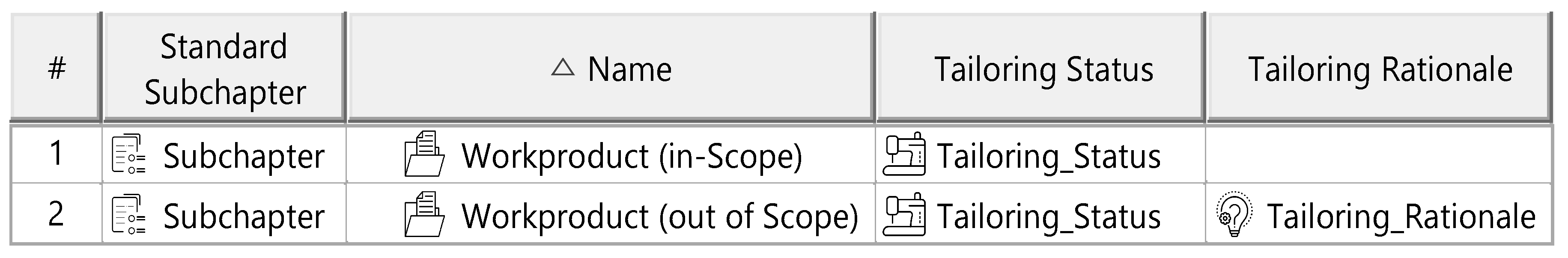
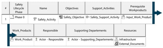
Figure A3.
Safety activities template.
Figure A3.
Safety activities template.

Figure A4.
Safety support activities template.
Figure A4.
Safety support activities template.


Figure A5.
Time plan template.
Figure A5.
Time plan template.

Appendix J. Artifacts of the Unified ITEM Definition

Figure A6.
ITEM interface template.
Figure A6.
ITEM interface template.
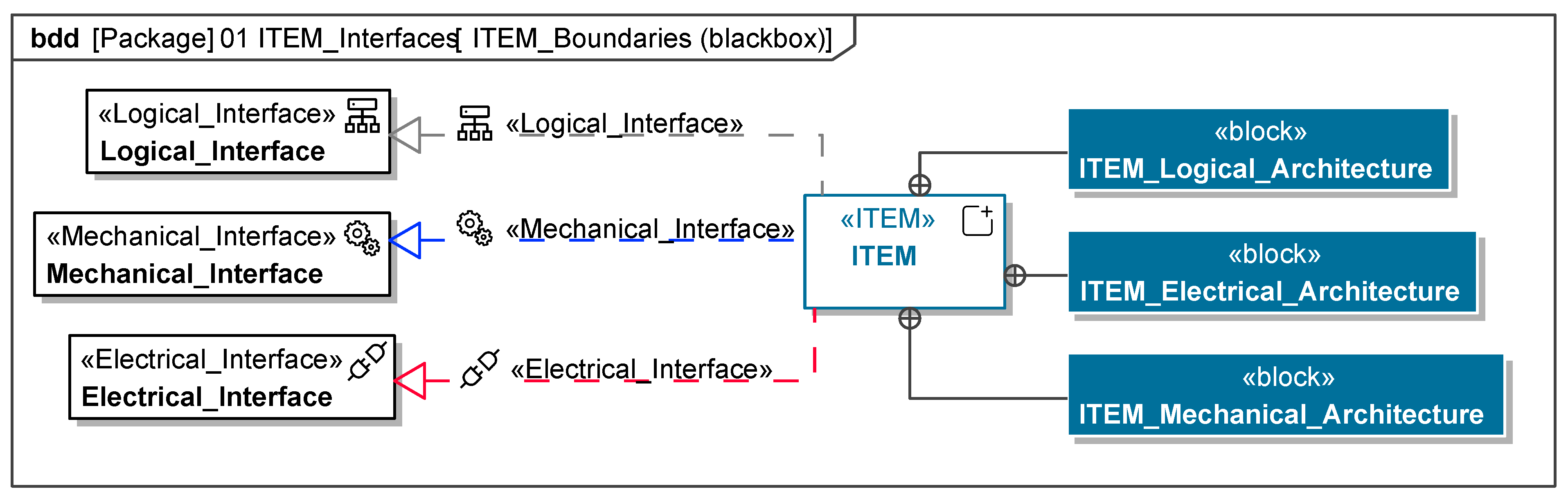
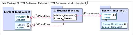
Figure A7.
ITEM architecture template.
Figure A7.
ITEM architecture template.
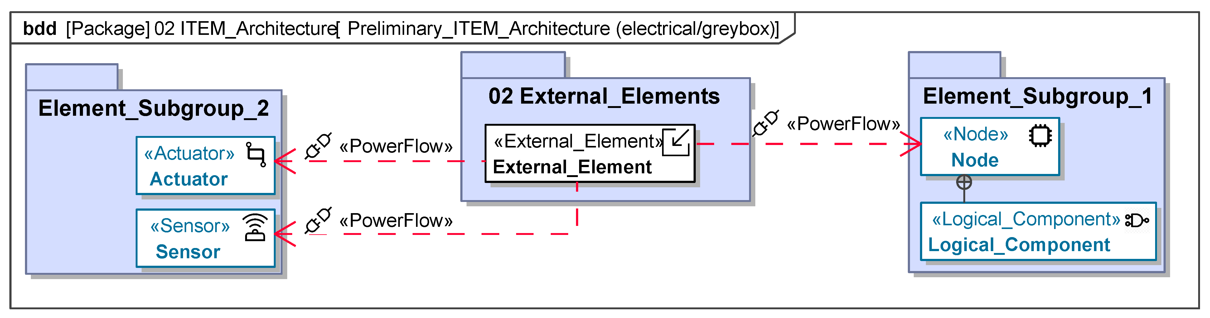
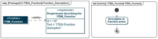
Figure A8.
ITEM functions template.
Figure A8.
ITEM functions template.
Appendix K. Artifacts of the Hazard Analysis and Risk Assessment
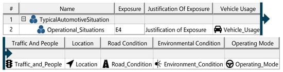
Figure A9.
Operational situations template.
Figure A9.
Operational situations template.

Figure A10.
Malfunction HazOp template.
Figure A10.
Malfunction HazOp template.
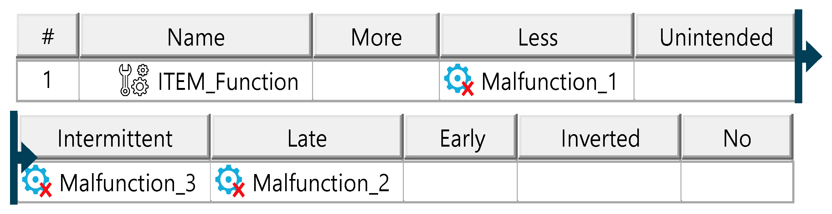
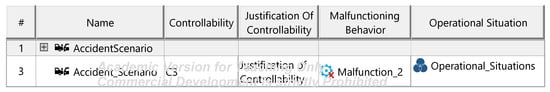
Figure A11.
Accident scenarios template.
Figure A11.
Accident scenarios template.

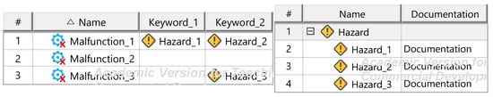
Figure A12.
Hazard identification und documentation templates.
Figure A12.
Hazard identification und documentation templates.
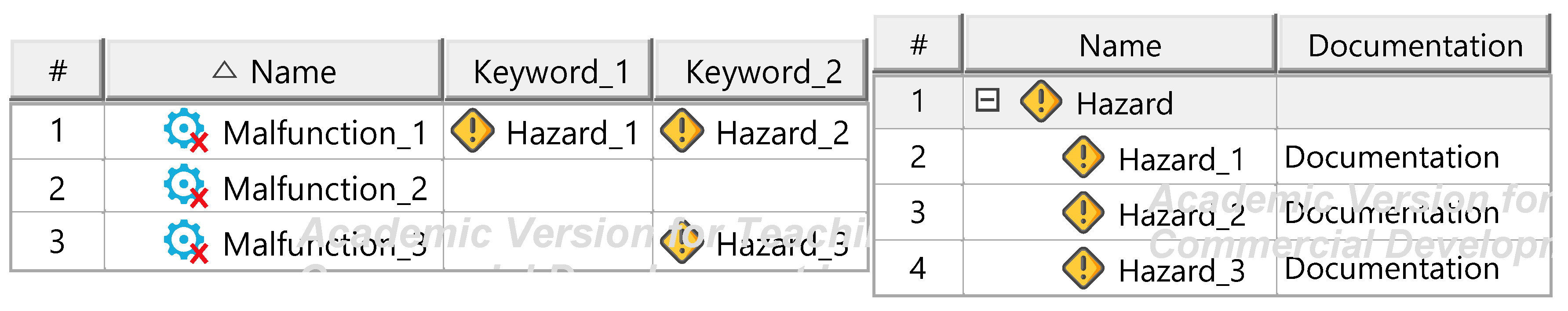
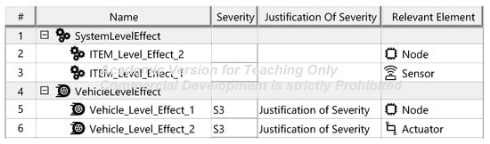
Figure A13.
Effects—template.
Figure A13.
Effects—template.
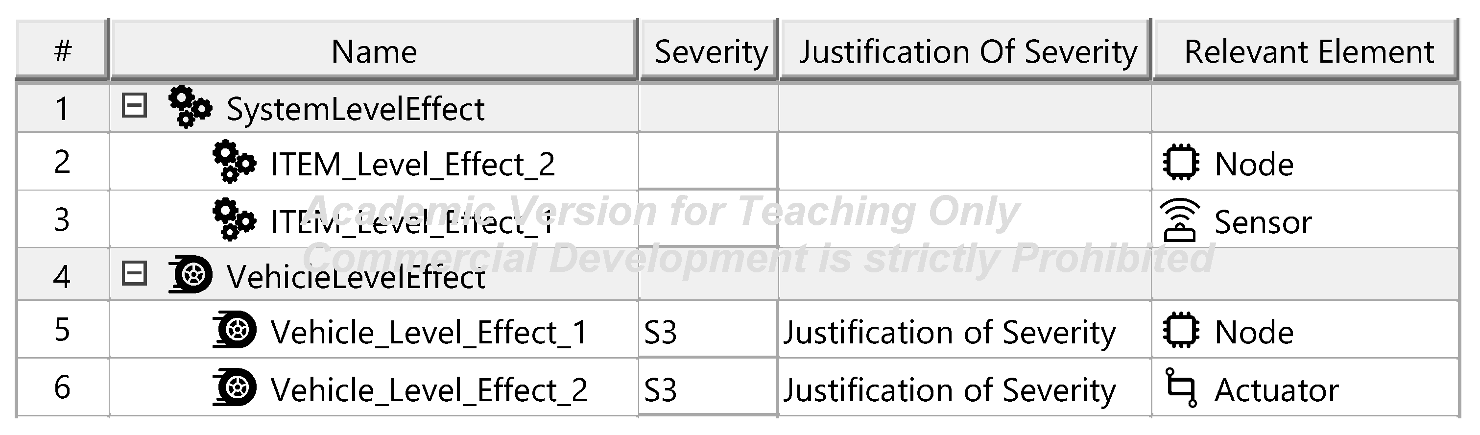
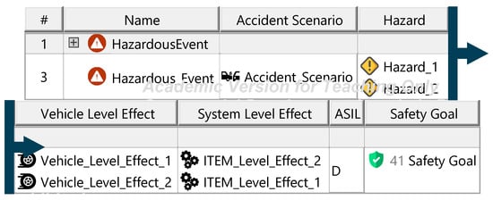
Figure A14.
Safety goals—template.
Figure A14.
Safety goals—template.

Appendix L. Artifacts of the Threat Analysis and Risk Assessment
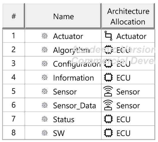
Figure A15.
Asset identification—template.
Figure A15.
Asset identification—template.
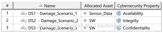
Figure A16.
Damage scenarios—template.
Figure A16.
Damage scenarios—template.
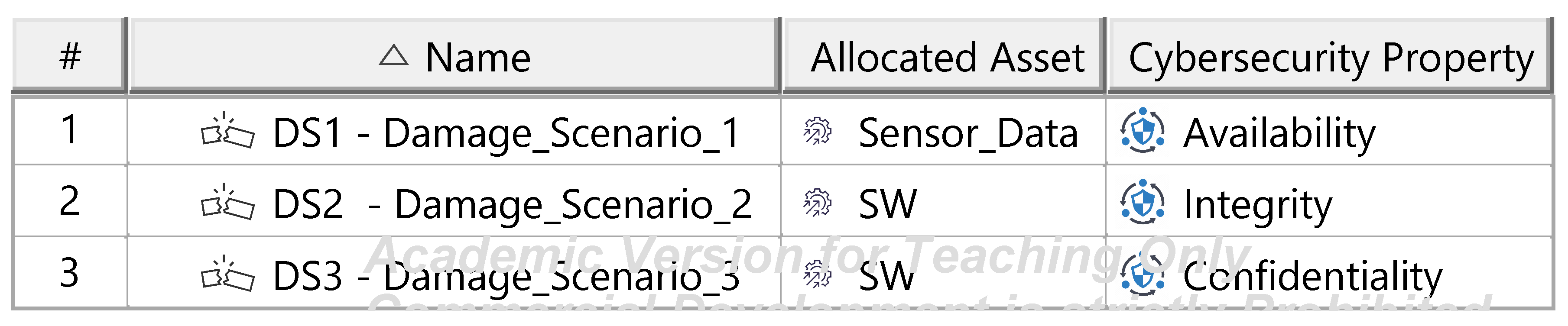
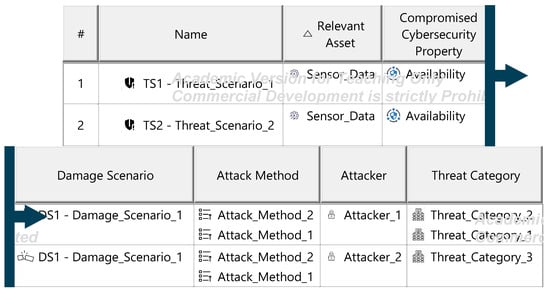
Figure A17.
Threat scenarios—template.
Figure A17.
Threat scenarios—template.
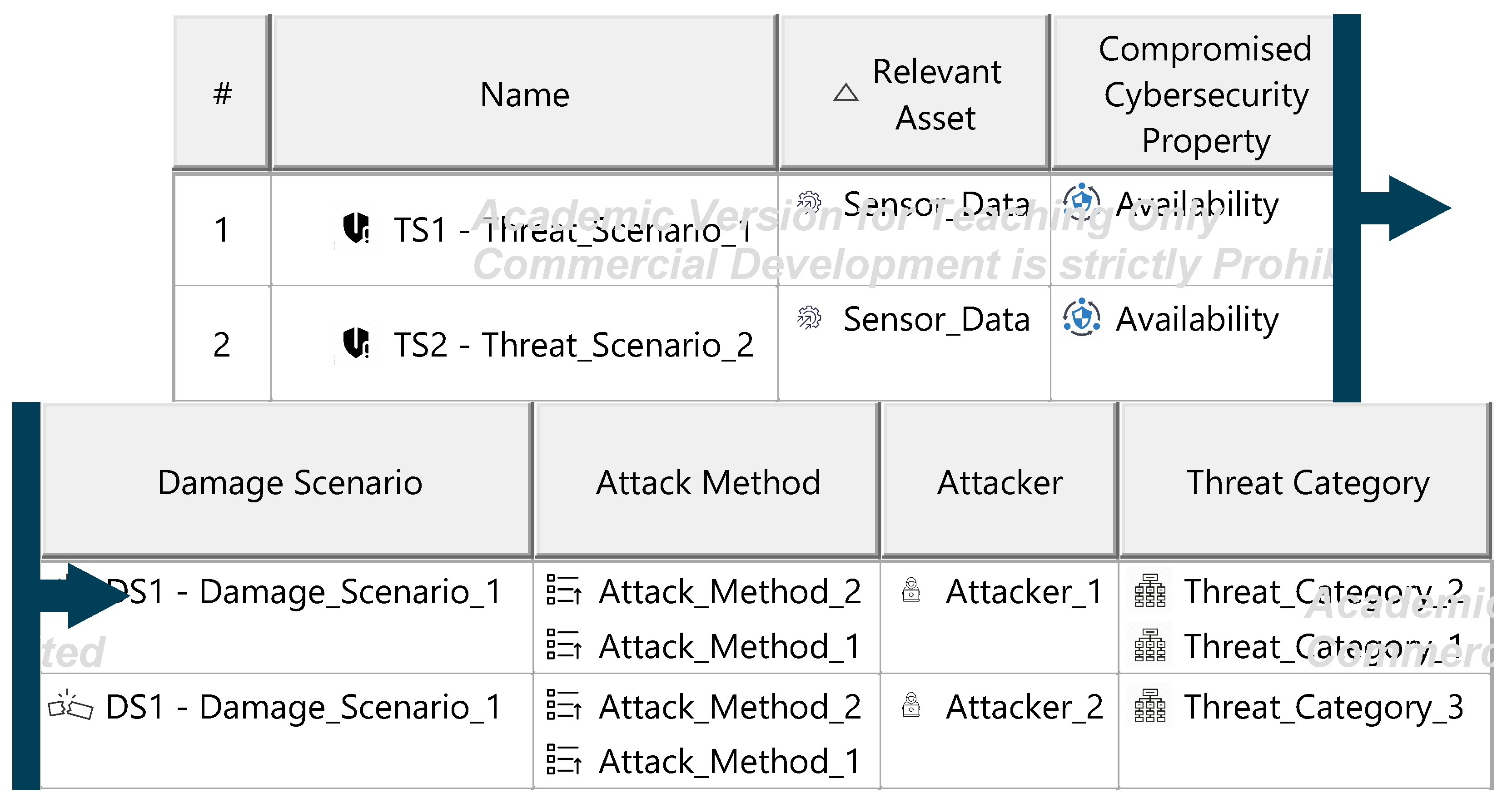
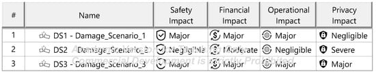
Figure A18.
Impact rating—template.
Figure A18.
Impact rating—template.
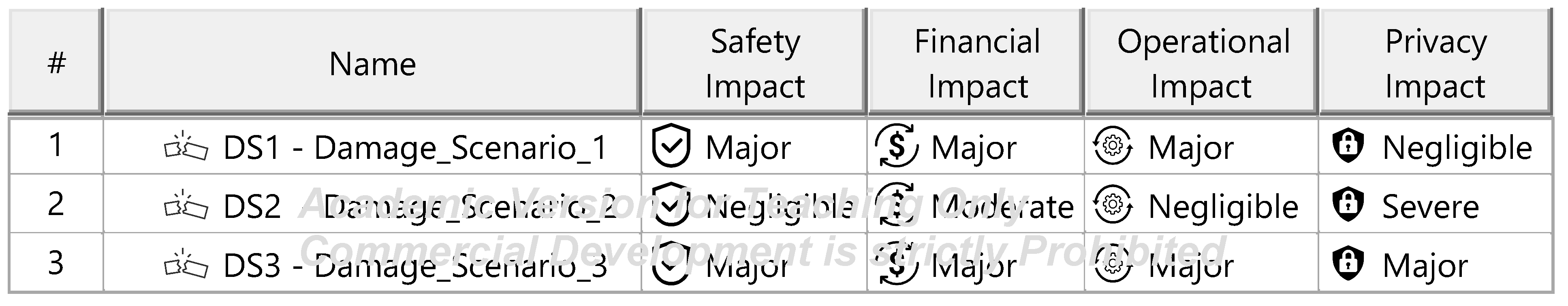
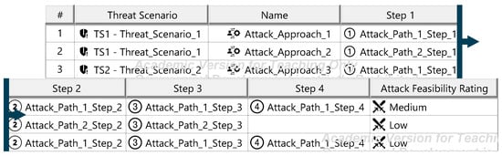
Figure A19.
Attack paths—template.
Figure A19.
Attack paths—template.
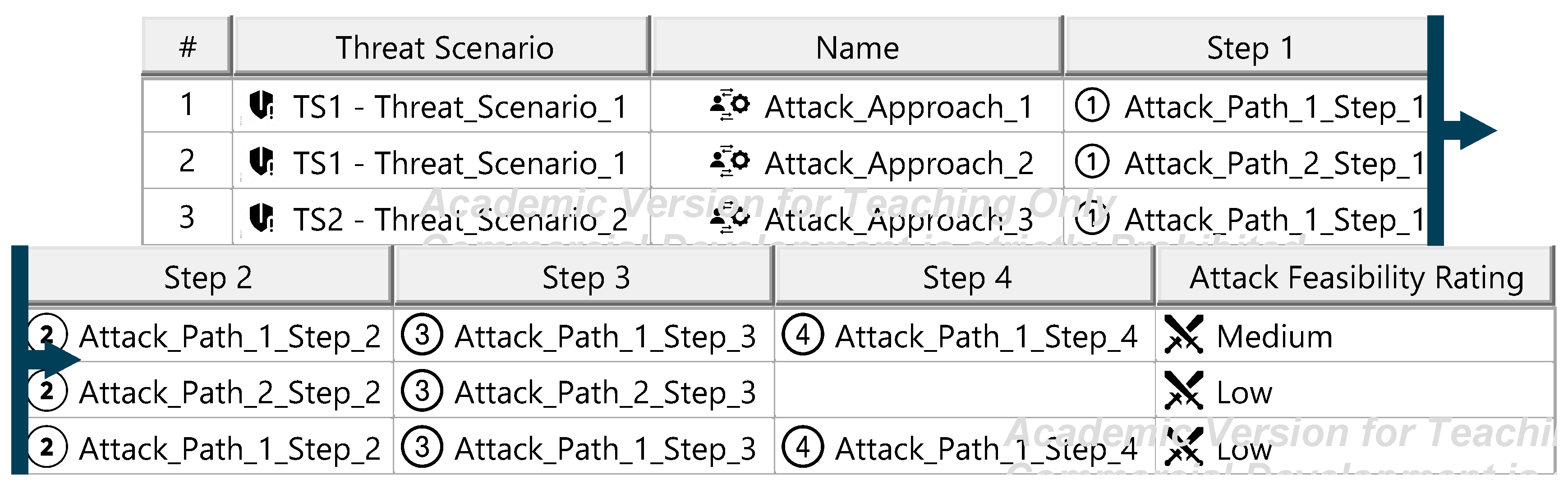
Figure A20.
Attack feasibility rating—template.
Figure A20.
Attack feasibility rating—template.
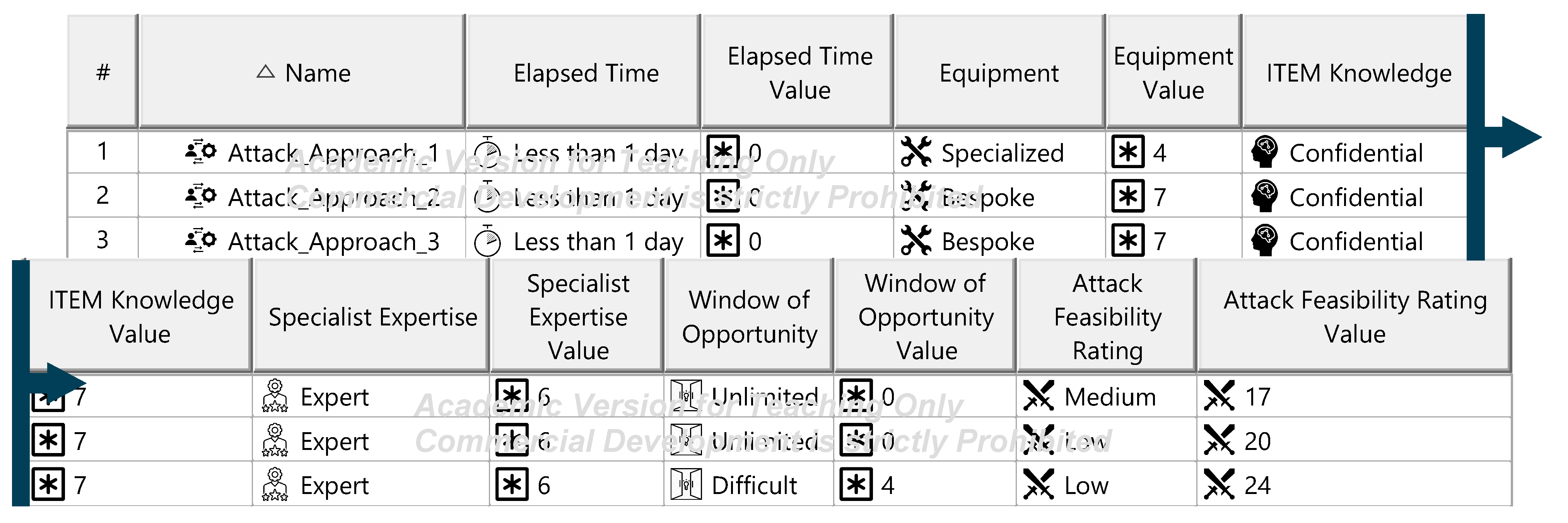
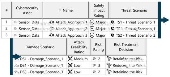
Figure A21.
Safety risk rating—template.
Figure A21.
Safety risk rating—template.
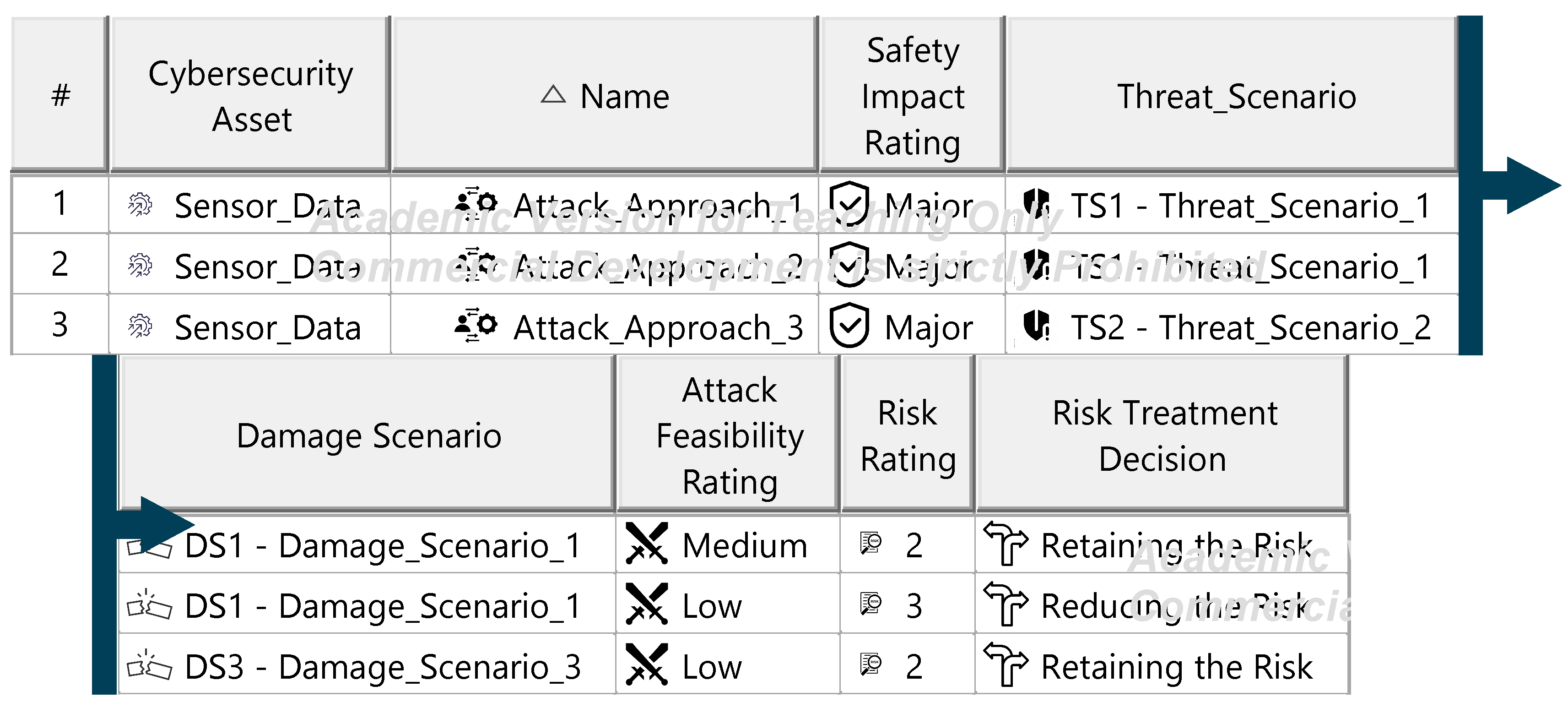
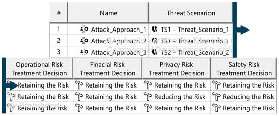
Figure A22.
Risk Treatment decisions overview—template.
Figure A22.
Risk Treatment decisions overview—template.
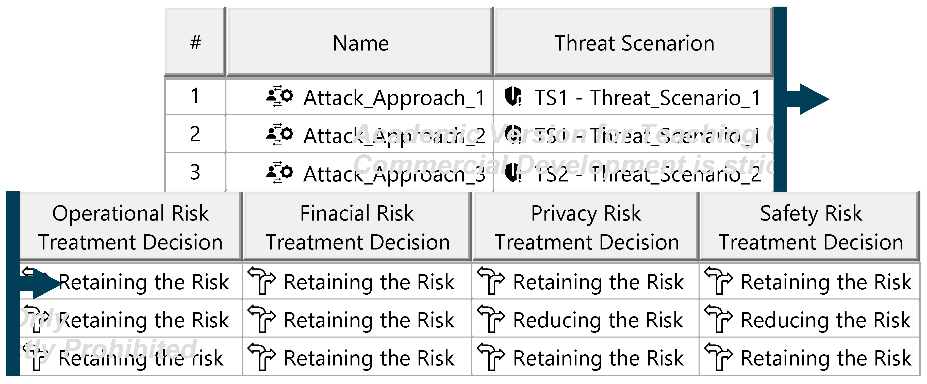
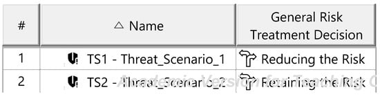
Figure A23.
Final risk treatment decisions—template.
Figure A23.
Final risk treatment decisions—template.
Appendix M. Artifacts of the Functional Safety Concept

Figure A24.
Functional safety strategy—template.
Figure A24.
Functional safety strategy—template.

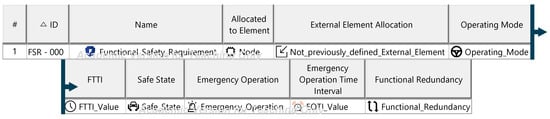
Figure A25.
Functional safety requirement specification—template.
Figure A25.
Functional safety requirement specification—template.
Appendix N. Artifacts of the Technical Safety Concept

Figure A26.
Technical safety requirements specification—template.
Figure A26.
Technical safety requirements specification—template.

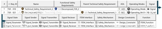
Figure A27.
Technical safety requirements specification—template.
Figure A27.
Technical safety requirements specification—template.
Appendix O. Artifacts of the Security Concept

Figure A28.
Cybersecurity claims specification—template.
Figure A28.
Cybersecurity claims specification—template.

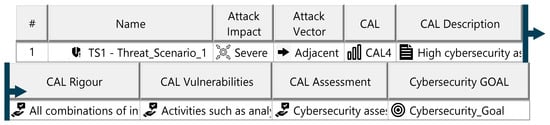
Figure A29.
Cybersecurity goals specification—template.
Figure A29.
Cybersecurity goals specification—template.
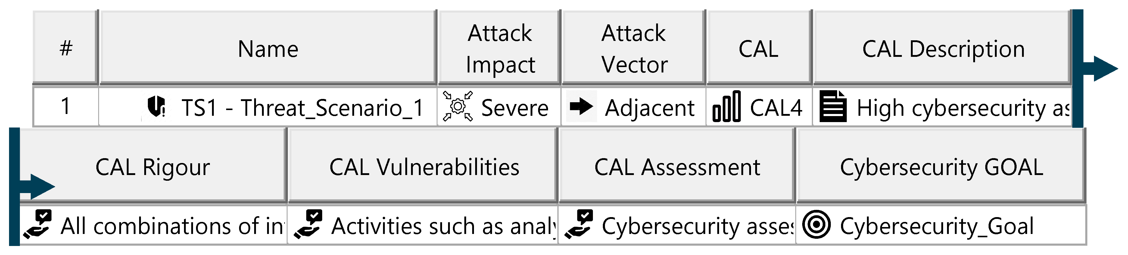
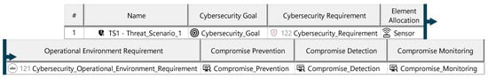
Figure A30.
Cybersecurity requirements specification—template.
Figure A30.
Cybersecurity requirements specification—template.
References
- Kifor, C.V.; Popescu, A. Automotive Cybersecurity: A Survey on Frameworks, Standards, and Testing and Monitoring Technologies. Sensors 2024, 24, 6139. [Google Scholar] [CrossRef] [PubMed]
- Ayres, N.; Deka, L.; Paluszczyszyn, D. Continuous Automotive Software Updates through Container Image Layers. Electronics 2021, 10, 739. [Google Scholar] [CrossRef]
- Gausemeier, J.; Moehringer, S. VDI 2206—A New Guideline for the Design of Mechatronic Systems. IFAC Proc. Vol. 2002, 35, 785–790. [Google Scholar] [CrossRef]
- Gräßler, I.; Oleff, C. Systems Engineering: Verstehen und Industriell Umsetzen; Springer: Berlin, Germany, 2022. [Google Scholar]
- Nolte, B.; Gollnick, D.; Stein, A.; Vietor, T. Development of a Method for Evaluating H2-Filling Stations. Hydrogen 2024, 5, 851–871. [Google Scholar] [CrossRef]
- Walden, D.D.; Roedler, G.J.; Forsberg, K.; Hamelin, R.D.; Shortell, T.M.; International Council on Systems Engineering (Eds.) Systems engineering Handbook: A Guide for System Life Cycle Processes and Activities, 4th ed.; Wiley: Hoboken, NJ, USA, 2015. [Google Scholar]
- Long, D.; Scott, Z. A Primer for Model-Based Systems Engineering. 2012. Available online: http://ccose.org/media/upload/MBSE_Primer_2ndEdition_full_Vitech_2011.10.pdf (accessed on 17 November 2023).
- Delligatti, L. SysML Distilled: A Brief Guide to the Systems Modeling Language; Addison-Wesley: Upper Saddle River, NJ, USA, 2014; ISBN 0321927869. [Google Scholar]
- ISO 26262:2018; Road Vehicles—Functional Safety. ISO: Geneva, Switzerland, 2018. Available online: https://www.iso.org/standard/68383.html (accessed on 17 November 2023).
- Kriaa, S.; Pietre-Cambacedes, L.; Bouissou, M.; Halgand, Y. A survey of approaches combining safety and security for industrial control systems. Reliab. Eng. Syst. Saf. 2015, 139, 156–178. [Google Scholar] [CrossRef]
- Furrer, F.J. Safety and Security of Cyber-Physical Systems: Engineering Dependable Software Using Principle-Based Development; Springer: Berlin/Heidelberg, Germany, 2022. [Google Scholar] [CrossRef]
- ISO 21434:2021; Road vehicles—Cybersecurity Engineering. ISO: Geneva, Switzerland, 2021. Available online: https://www.iso.org/standard/70918.html (accessed on 17 November 2023).
- Regulation (EU) 2016/679 of the European Parliament and of the Council of 27 April 2016 on the Protection of Natural Persons with Regard to the Processing of Personal Data and on the Free Movement of Such Data, and Repealing Directive 95/46/EC (General Data Protection Regulation) (Text with EEA Relevance) (OJ L 119 04.05.2016, p. 1). Available online: http://data.europa.eu/eli/reg/2016/679/oj (accessed on 17 November 2023).
- California Consumer Privacy Act (CCPA), as Amended by the California Privacy Rights Act (CPRA). Available online: https://leginfo.legislature.ca.gov/faces/codes_displayText.xhtml?lawCode=CIV&division=3.&title=1.81.5.&part=4.&chapter=&article= (accessed on 18 February 2025).
- Benyahya, M.; Collen, A.; Nijdam, N.A. Analyses on standards and regulations for connected and automated vehicles: Identifying the certifications roadmap. Transp. Eng. 2023, 14, 100205. [Google Scholar] [CrossRef]
- Benyahya, M.; Kechagia, S.; Collen, A.; Nijdam, N.A. The Interface of Privacy and Data Security in Automated City Shuttles: The GDPR Analysis. Appl. Sci. 2022, 12, 4413. [Google Scholar] [CrossRef]
- Liedtke, T. (Ed.) Funktionale Sicherheit (Safety). In Informationssicherheit; Springer: Berlin, Germany, 2022; pp. 89–106. [Google Scholar] [CrossRef]
- Meyers, B.; Gadeyne, K.; Oakes, B.; Bernaerts, M.; Vangheluwe, H.; Denil, J. A Model-Driven Engineering Framework to Support the Functional Safety Process. In Proceedings of the ACM/IEEE 22nd International Conference on Model Driven Engineering Languages and Systems Companion (MODELS-C), Munich, Germany, 15–20 September 2019; pp. 619–623. [Google Scholar] [CrossRef]
- Frese, T.; Gerber, N.; Hatebur, D.; Côté, I.; Heisel, M. Functional Safety Processes and Advanced Driver Assistance Systems: Evolution or Revolution? In Mobilität und digitale Transformation; Proff, H., Fojcik, T.M., Eds.; Springer: Wiesbaden, Germany, 2018; pp. 199–216. [Google Scholar] [CrossRef]
- Valdivia Dabringer, M.L.; Dybov, A.; Fresemann, C.; Stark, R. Towards Integrated Safety Analysis as Part of Traceable Model-Based Systems Engineering. Proc. Des. Soc. 2022, 2, 2005–2014. [Google Scholar] [CrossRef]
- Biggs, G.; Juknevicius, T.; Armonas, A.; Post, K. Integrating Safety and Reliability Analysis into MBSE: Overview of the new proposed OMG standard. INCOSE Int. Symp. 2018, 28, 1322–1336. [Google Scholar] [CrossRef]
- Biggs, G.; Post, K.; Armonas, A.; Yakymets, N.; Juknevicius, T.; Berres, A. OMG standard for integrating safety and reliability analysis into MBSE: Concepts and applications. INCOSE Int. Symp. 2019, 29, 159–173. [Google Scholar] [CrossRef]
- Mažeika, D.; Butleris, R. Integrating Security Requirements Engineering into MBSE: Profile and Guidelines. Secur. Commun. Netw. 2020, 2020, 5137625. [Google Scholar] [CrossRef]
- Larsen, M.H.; Muller, G.; Kokkula, S. A Conceptual Model-Based Systems Engineering Method for Creating Secure Cyber-Physical Systems. INCOSE Int. Symp. 2022, 32, 202–213. [Google Scholar] [CrossRef]
- Oates, R.; Thom, F.; Herries, G. Security-Aware, Model-Based Systems Engineering with SysML. In Proceedings of the 1st International Symposium for ICS & SCADA Cyber Security Research 2013, (ICS-CSR 2013), Leicester, UK, 16–17 September 2013. [Google Scholar] [CrossRef]
- Häring, I.; Sudheedran, V.; Sankin, R.; Hiermaier, S. Joint Functional Safety ISO 26262 and Cybersecurity STRIDE/HEAVENS Assessment by Developers within MBSE SPES Framework Using Extended SysML Diagrams and Minor Automations; International Association for Probabilistic Safety Assessment and Management (IAPSAM): Seal Beach, CA, USA, 2022; Available online: https://www.iapsam.org/PSAM16/papers/IV42-PSAM16.pdf (accessed on 17 November 2023).
- Japs, S.; Anacker, H.; Dumitrescu, R. SAVE: Security & safety by model-based systems engineering on the example of automotive industry. Procedia CIRP 2021, 100, 187–192. [Google Scholar] [CrossRef]
- NoMagic. ISO 26262 Functional Safety. Available online: https://docs.nomagic.com/display/CSRA190SP3/ISO+26262+Functional+Safety (accessed on 15 December 2024).
- NoMagic. ISO 21434 Cybersecurity. Available online: https://docs.nomagic.com/display/CSRA2024x/ISO+21434+Functional+Cybersecurity (accessed on 15 December 2024).
- Morkevicius, A.; Aleksandraviciene, A.; Mazeika, D.; Bisikirskiene, L.; Strolia, Z. MBSE Grid: A Simplified SysML-Based Approach for Modeling Complex Systems. INCOSE Int. Symp. 2017, 27, 136–150. [Google Scholar] [CrossRef]
- European Union Agency for Cybersecurity. ENISA Good Practices for the Security of Smart Cars; ENISA: Athens, Greece, 2019; Available online: https://data.europa.eu/doi/10.2824/17802 (accessed on 17 November 2023).
- United Nations Economic Commission for Europe. UN ECE R 155; UNECE: Geneva, Switzerland, 2021. [Google Scholar]
- ISO 21448:2022; Road Vehicles—Safety of the Intended Functionality. ISO: Geneva, Switzerland, 2022. Available online: https://www.iso.org/standard/77490.html (accessed on 17 November 2023).
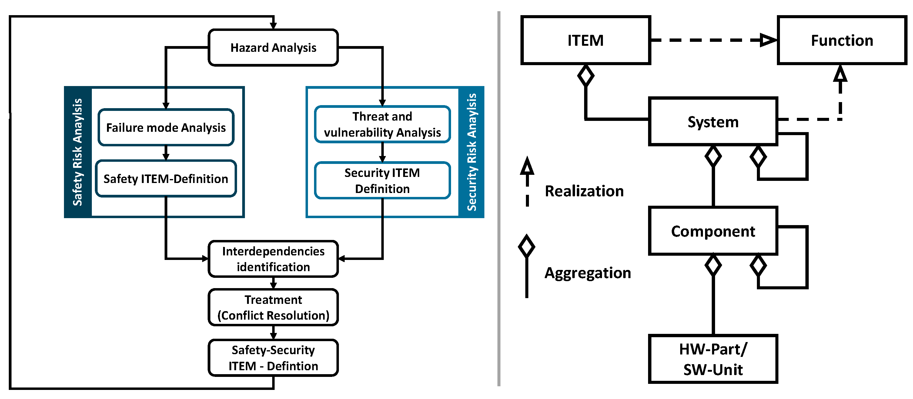
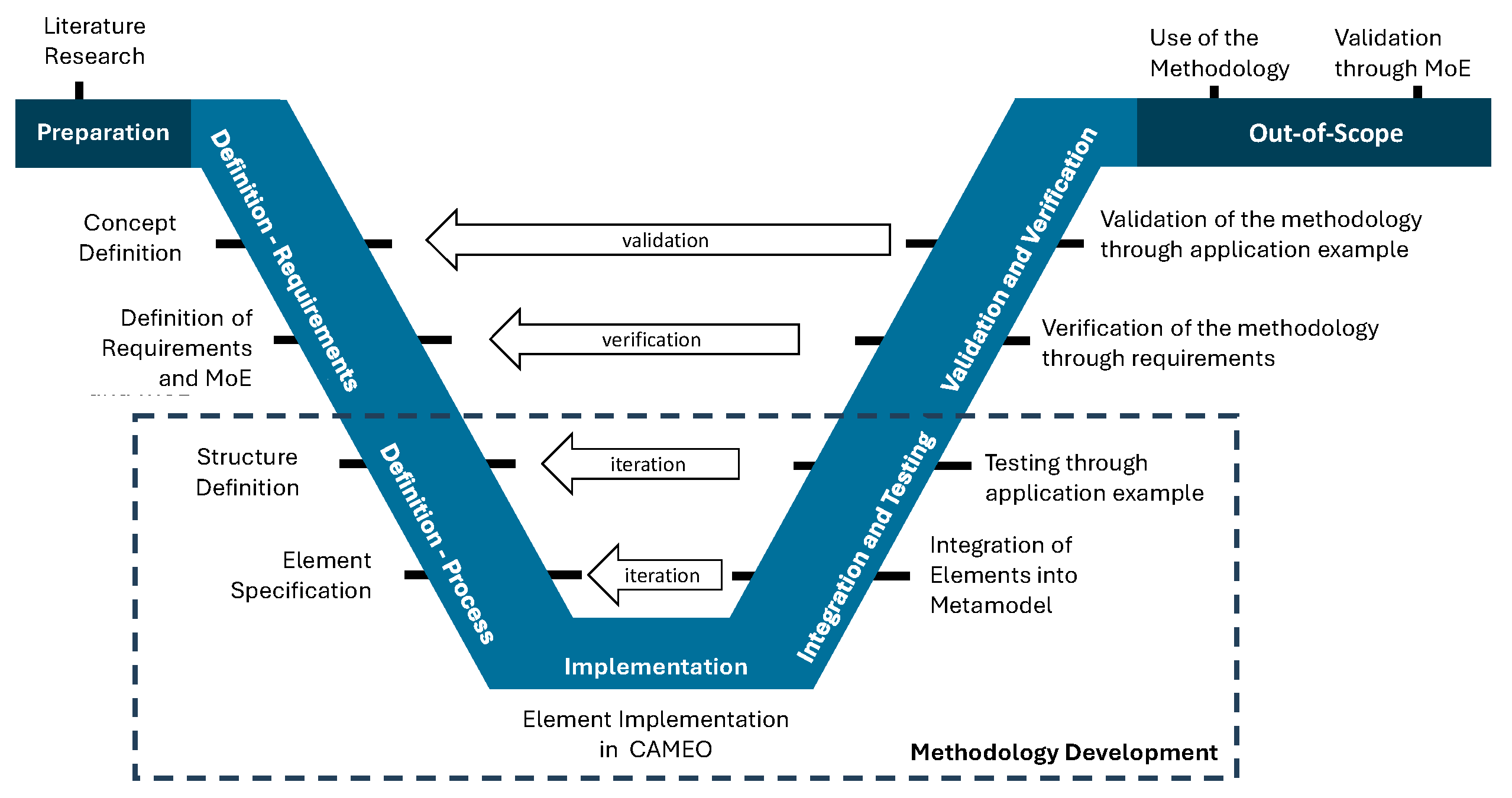
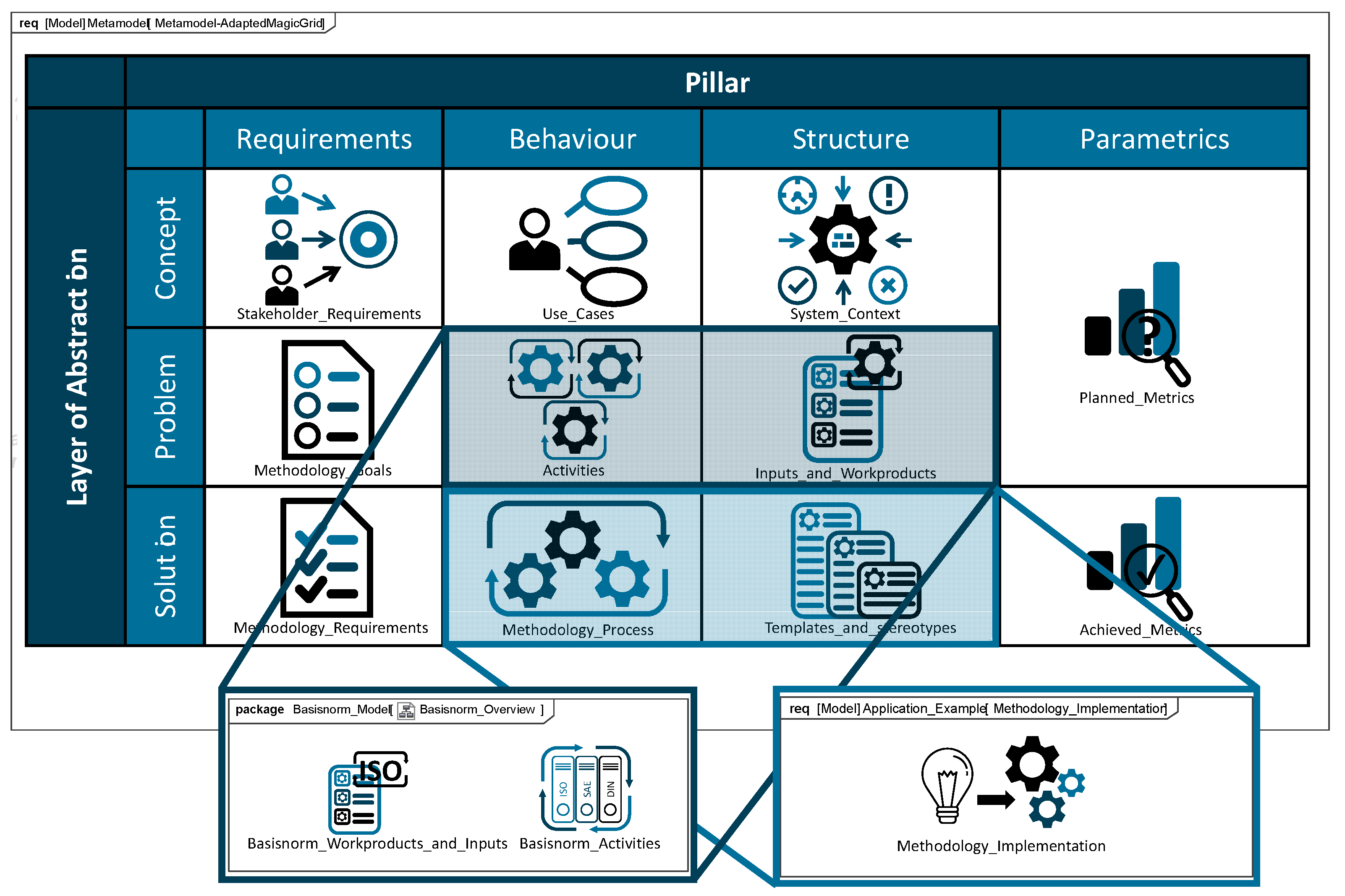
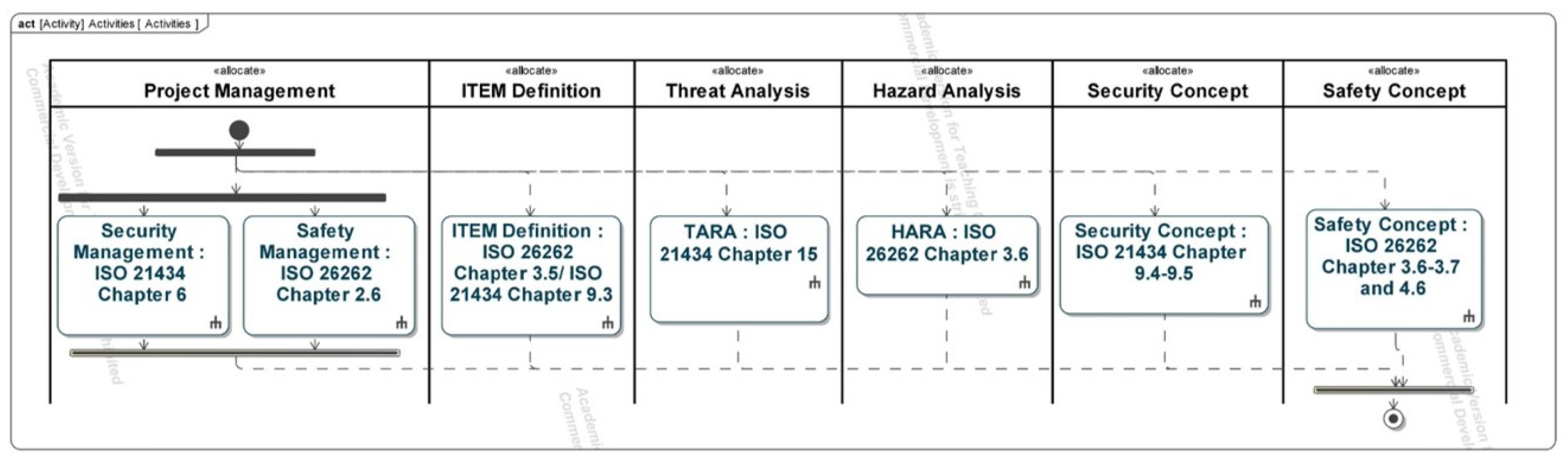
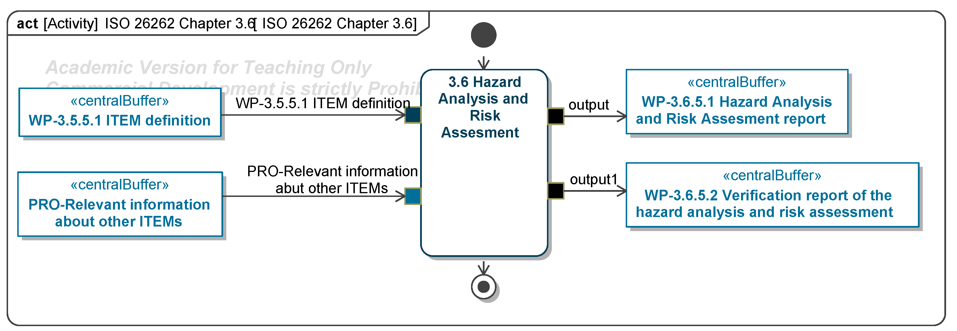
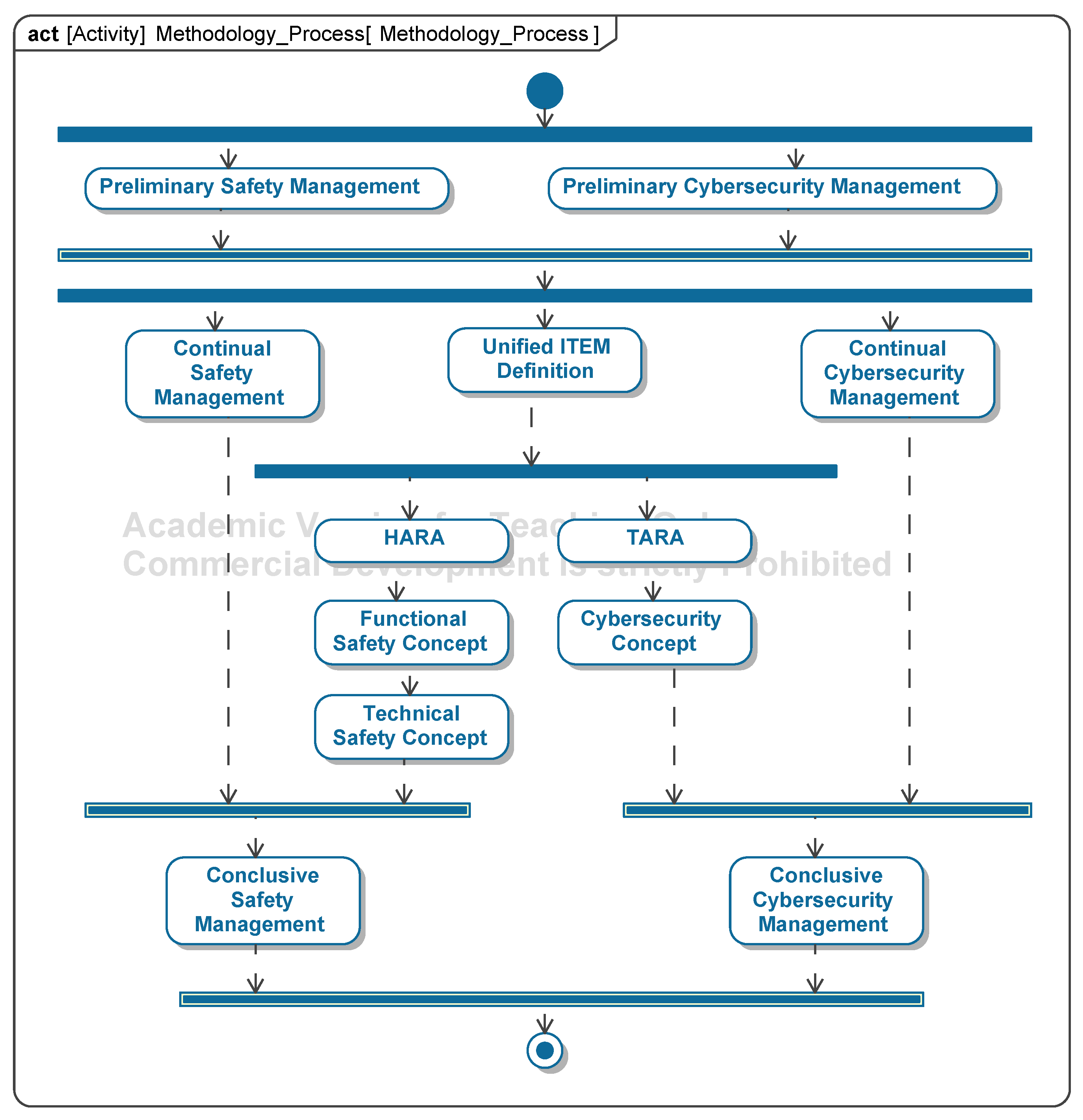
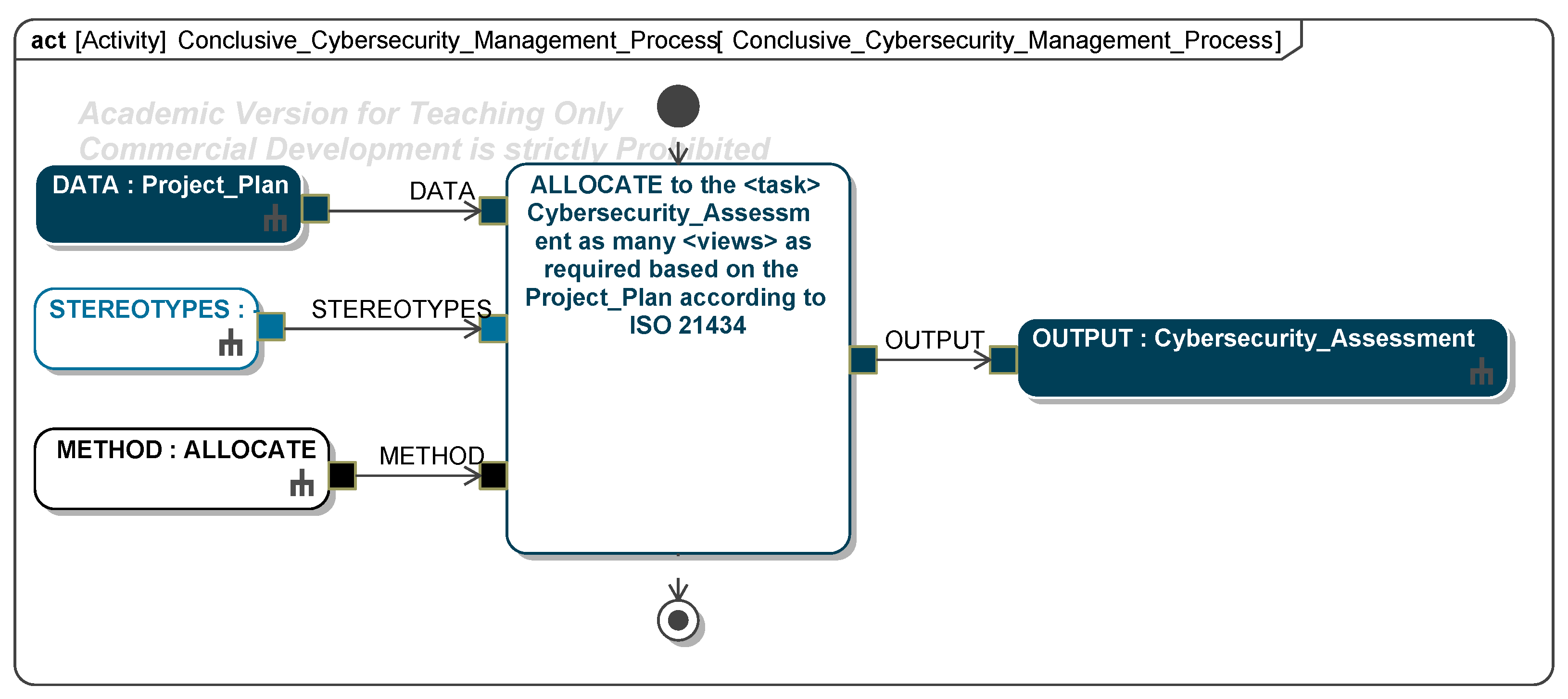
Disclaimer/Publisher’s Note: The statements, opinions and data contained in all publications are solely those of the individual author(s) and contributor(s) and not of MDPI and/or the editor(s). MDPI and/or the editor(s) disclaim responsibility for any injury to people or property resulting from any ideas, methods, instructions or products referred to in the content. |
© 2025 by the authors. Published by MDPI on behalf of the International Institute of Knowledge Innovation and Invention. Licensee MDPI, Basel, Switzerland. This article is an open access article distributed under the terms and conditions of the Creative Commons Attribution (CC BY) license (https://creativecommons.org/licenses/by/4.0/).