1. Introduction
Particle-beam and plasma technologies are used in many applications for the modification of materials for various purposes, such as electron beam welding [
1,
2], plasma surface treatment [
3,
4,
5,
6], coating synthesis [
7,
8], etc. The electron beam evaporation of oxide targets is a promising method for the deposition of coatings with different functional properties [
9]. A principal advantage of evaporation over ion sputtering is the faster deposition rate, which reduces the processing time. Since oxide materials are, as a rule, dielectrics, the accumulation of negative charge on the dielectric target is inevitable, which can cause the deflection and deceleration of the electron beam [
10]. Another problem is the dissociation of oxides during evaporation, as a result of which the chemical composition of the deposited film differs from that of the target due to oxygen deficiency [
11]. Both of these problems can be solved by using a fore-vacuum-pressure, plasma-cathode electron source [
12], in which the electron beam is formed from electron emission from a gas discharge plasma at operating pressures in the range of 1–50 Pa. Under these conditions, plasma is formed along the electron beam trajectory (the “beam-plasma”), from which positive ions ensure the neutralization of the negative charge brought to the dielectric target by the electron beam. The problem of oxygen deficiency in the deposition can be avoided by carrying out the evaporation process in oxygen or an oxygen-containing environment. At the same time, despite the fact that plasma electron sources do not contain heated electrodes, the degradation of the electrodes under the action of oxygen plasma and, as a result, changes in the source characteristics cannot be ruled out. The purpose of the work described here was to investigate the performance and characteristics of a plasma electron source in oxygen in comparison with its behavior in other gaseous media.
2. Materials and Methods
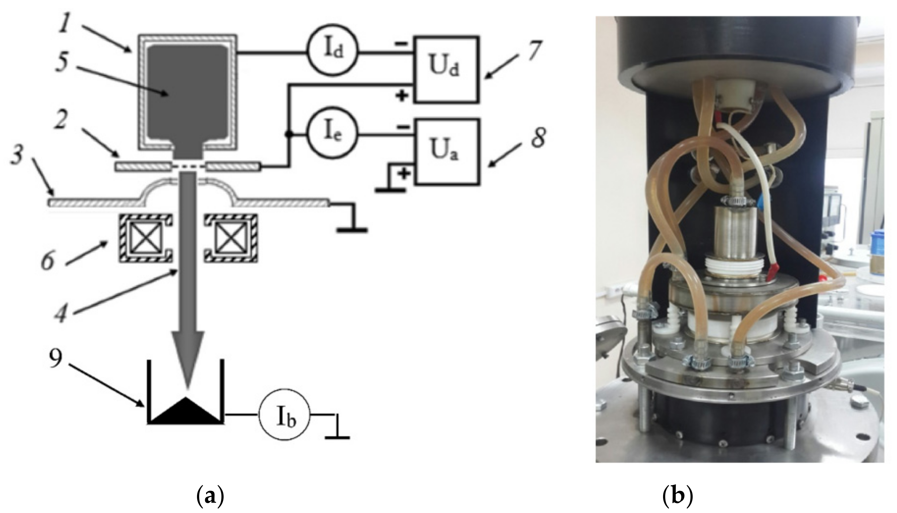
The experiment was carried out using a fore-vacuum-pressure, plasma-cathode electron source utilizing a hollow cathode discharge. The main elements of the source and a photograph are shown in
Figure 1a,b.
A discharge with a hollow cathode 1 made of stainless steel with a diameter of 30 mm and a length of 80 mm was used in the source as the emission plasma generator. Anode 2 contained an emission window covered with a tantalum grid with 120 emission holes with a diameter of 0.7 mm. Holes were evenly distributed over the emission electrode over an area with a diameter of 13 mm. Beam accelerating voltage
Ua was applied across the gap between anode 2 and accelerating electrode 3, located at a distance of 10 mm from the emission electrode. The hole in the extractor for propagation of the electron beam had a diameter of 15 mm. Electron beam 4 was focused by magnetic lens 6 and was terminated at collector 9 (Faraday cup), which served to measure beam current
Ib. For the purposes of this study, the source was upgraded with thicker tantalum emission grids compared to those described in [
3]. This made it possible to somewhat reduce the thermal load on the emission electrode by improving heat removal. The discharge and emission characteristics of the source were measured using four gases: argon, nitrogen, helium, and oxygen. After the vacuum chamber was evacuated to a pressure of 1 Pa, the working gas was admitted. The discharge was then ignited by application of voltage
Ud, and the electron beam was formed upon increase in accelerating voltage
Ua. Gas pressure
p, current
Id, and voltage
Ud of the discharge, as well as the accelerating voltage
Ua and current
Ib of the beam, were monitored. Gas pressure
p was measured by a thermocouple vacuum gauge. The discharge voltage
Ud, accelerating voltage
Ua, and discharge current
Id were measured according to the electrical circuit shown in
Figure 1a. Among these measured parameters, the beam current
Ib had the maximum systematic error due to the formation of beam plasma in the area of its transportation. Thus, the collector current, identified as the beam current
Ib, was distorted by the fraction of the current of the beam plasma particles to the collector. The estimated error in the measurement of the beam current values due to this factor is presented in experimental graphs in the next section.
3. Results and Discussion
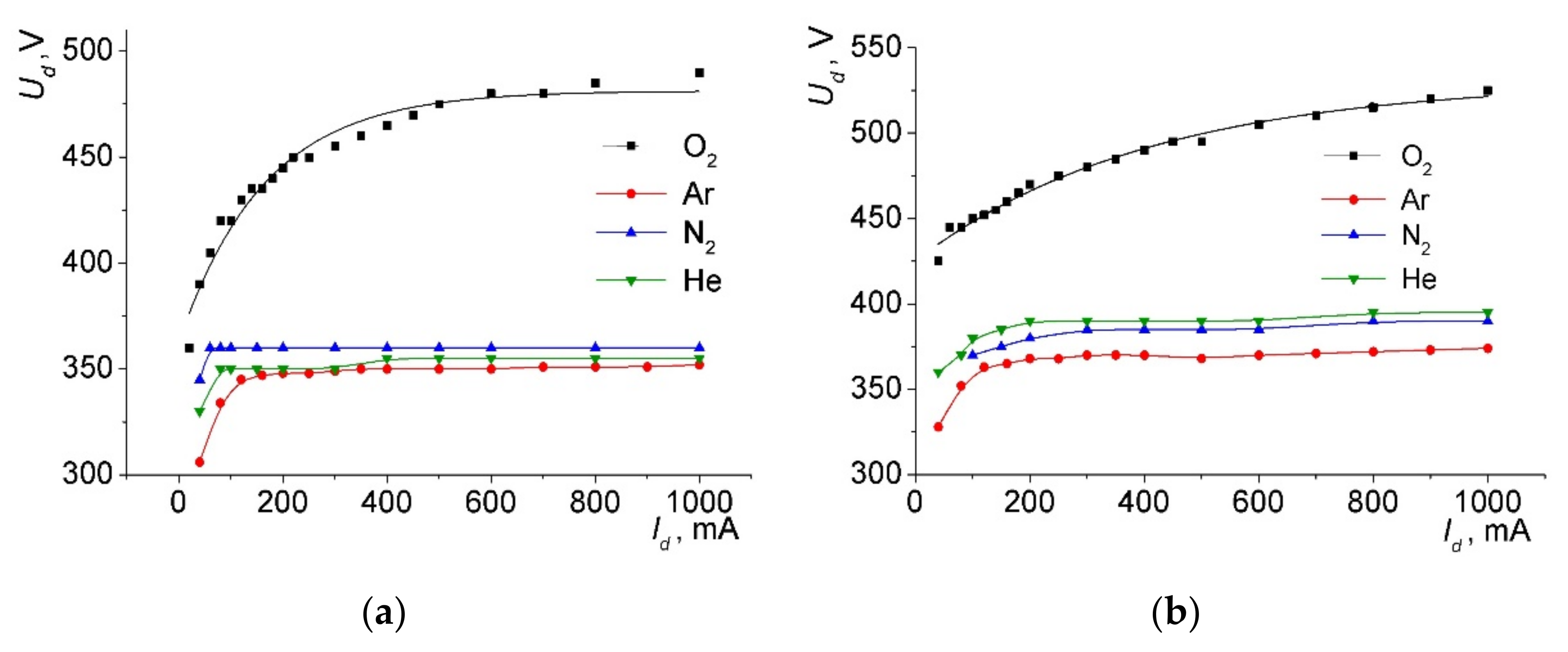
Figure 2 shows the current–voltage characteristics (CVC) of the hollow cathode discharge, which served as a plasma generator in the electron source. In
Figure 2, 4–6 curves drawn through the experimental data points were obtained by spline interpolation. The resulting form of the current–voltage characteristic (
Figure 2) is similar to the glow discharge used in discharge-emission systems with various configurations [
13,
14,
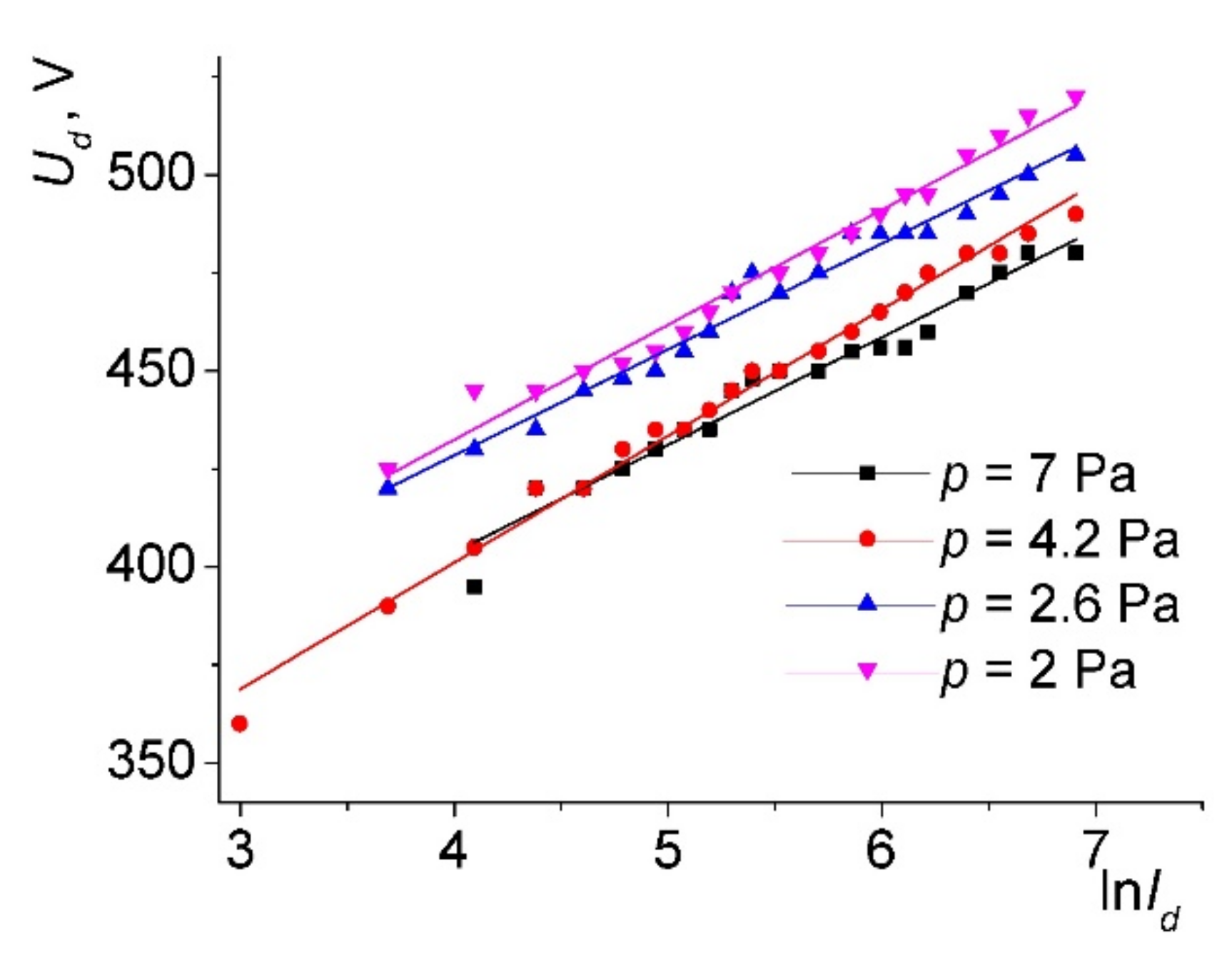
15]: the discharge voltage increases with increasing current, and voltage saturation is observed. For nitrogen, argon, and helium as the working gases, the CVC became almost horizontal when the discharge current exceeded 100 mA. A different behavior was observed for oxygen—the voltage increased monotonically with the increasing current. Moreover, the dependence of the current on the voltage had an exponential character (
Figure 3), which was confirmed by a linear approximation of the dependencies on the graph at coordinates ln
Id,
Ud. This different kind of characteristic can be explained as follows. For the argon, nitrogen, and helium, a normal glow discharge regime was produced, characterized by the invariance of the voltage with the increasing current. When applied to a discharge with a hollow cathode, this may mean gradual filling of the cathode cavity with plasma. A different behavior in the case of oxygen can be considered as an anomalous glow discharge, in which an increase in voltage is required to increase the current, so that each electron ejected from the cathode wall due to ion-electron emission can produce a greater number of ionization events, thereby increasing the plasma density. Moreover, at least a part of these ionization events was carried out in the sheath, due to which these electrons had time to gain sufficient energy for ionization. In other words, the conditions for avalanche electron multiplication were created. The fact that the discharge voltages in the oxygen noticeably exceeded the analogous values of the other gases was apparently due to the formation of oxides on the electrode surfaces. In turn, the higher voltages meant a greater sheath thickness between the plasma and the cathode wall, which ensured ionization in the sheath.
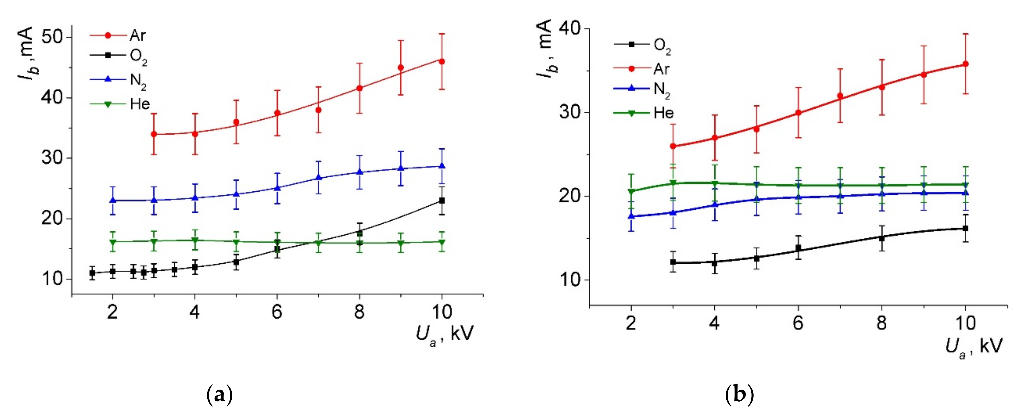
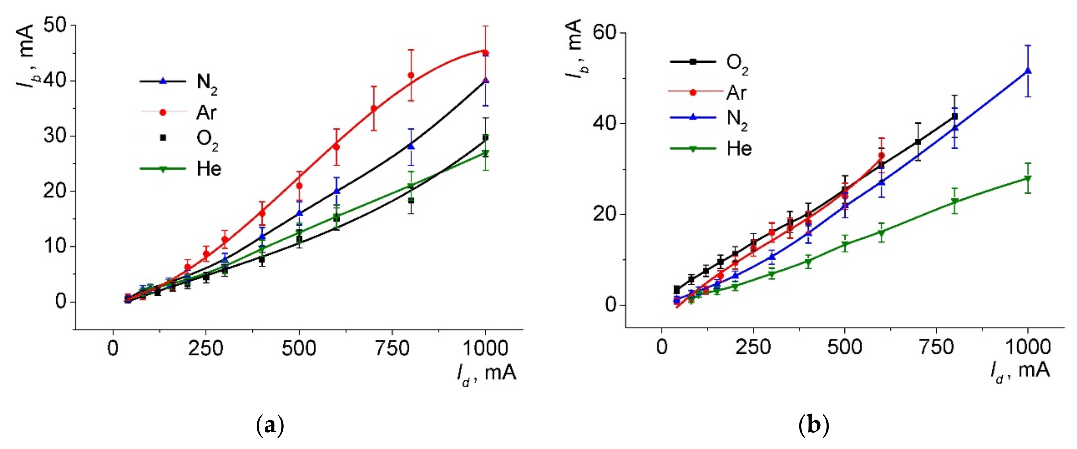
The dependencies of the beam current on the accelerating voltage are shown in
Figure 4. As can be seen, growing characteristics were observed for the oxygen, argon, and nitrogen, and the characteristics for the oxygen and argon had the greatest slope. The slope of the characteristics decreased with the decreasing gas pressure (
Figure 4b). For the helium, the beam current remained unchanged over the entire range of the accelerating voltage. At the same discharge currents and at accelerating voltages above 7 kV, for greater pressure (
Figure 4a), the electron beam current increased in the following order: He, O
2, N
2, Ar.
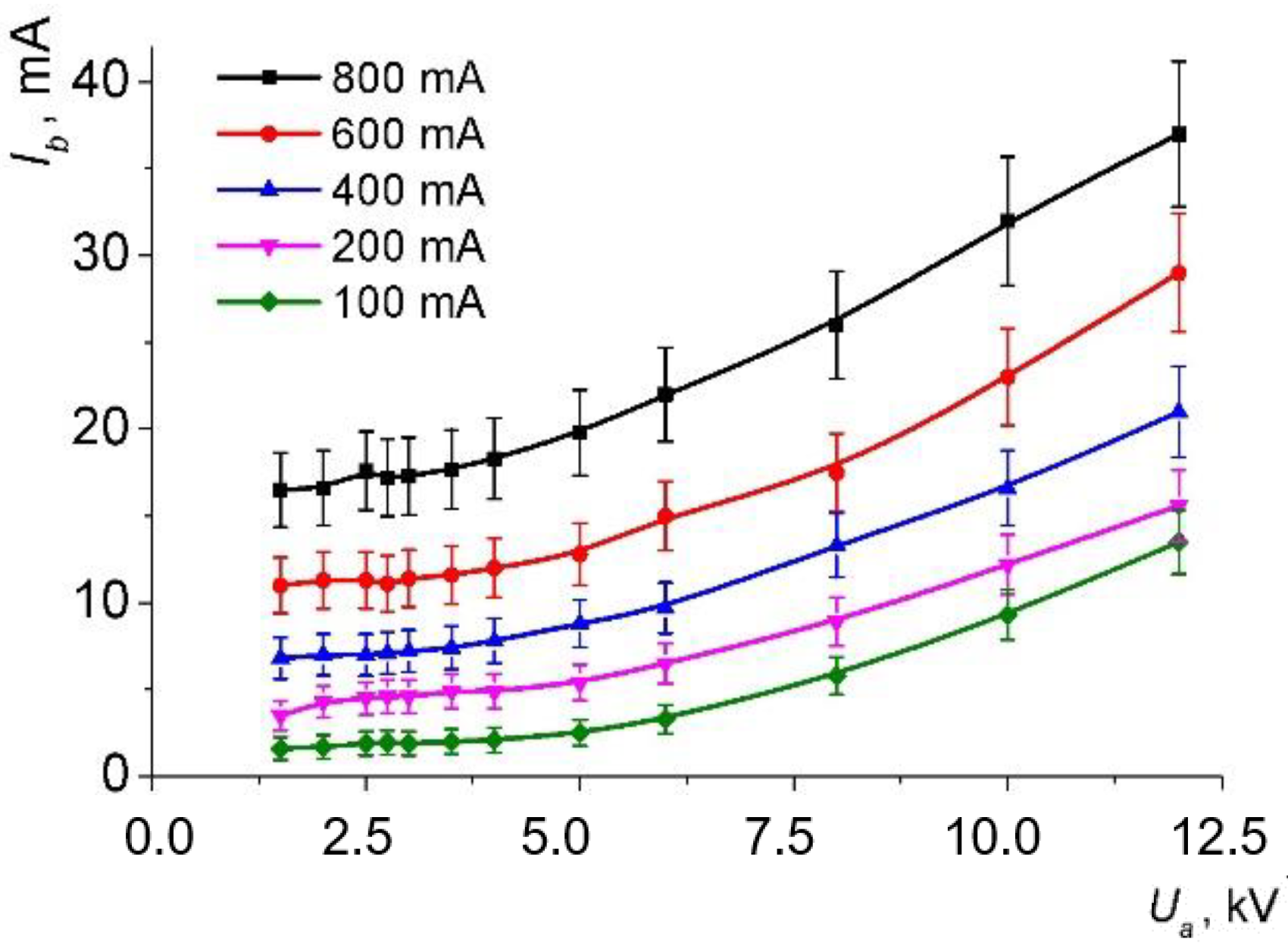
Figure 5 shows the dependence of the beam current
Ib on the accelerating voltage
Ua for various discharge currents
Id in oxygen. All the curves have the same form, which may indicate the same mechanism for the increase in
Ib with increasing
Ua. The dependencies of the beam current
Ib on the discharge current
Id were close to linear (
Figure 6). The relationship between the beam currents was the same as in
Figure 4. The largest currents were observed for the argon, and the smallest for the helium.
It should be noted that the effect of an increase in emissions and in the beam current from the accelerating voltage is typical for plasma sources during emission from the plasma at elevated pressures of the working gas only (above units of pascals) [
16]. For plasma sources operating at pressures of 0.01–0.1 Pa, the entire increase in the emission current occurs only in the initial part of the dependence at voltages not exceeding a few kilovolts [
15,
17]. Only when particles are emitted from the plasma through a single emission hole [
13,
17] can the growing section stretch up to ten kilovolts; however, in any case, the degree of increase in the emission current decreases with increasing accelerating voltage. At the same time, it can be seen from the results obtained in
Figure 4 and
Figure 5 that at elevated pressures, the slope of the dependence
Ib (
Ua) does not decrease with increasing accelerating voltage, but may even increase in some cases.
The indicated differences in the emission conditions can be explained by taking into account the presence of gas both in the beam propagation region and in the accelerating gap. Some conclusions can be drawn from a comparison of the ionization cross-sections for the gases used. According to [
18], for electron energies in the range of 1–10 keV, the ionization cross-sections decrease in the following order: Ar, N
2, O
2, He. Taking this into account, we can conclude that at a pressure of 4.2 Pa, the ratio between the beam currents for different gases can be due to both gas ionization in the accelerating gap and secondary electron emission from the tantalum grid under the action of ions emitted from the beam plasma and accelerated in the extractor-anode gap. An increase in beam current with increasing discharge current is quite expected, since the discharge current is directly related to the density of the emission plasma, and the current density
j of the emission from the open plasma boundary is described by the well-known relation
j =
env/4, where
v is the average thermal velocity of plasma electrons.


 ,
, 


