Article

Static and Dynamic Solutions of Functionally Graded Micro/Nanobeams under External Loads Using Non-Local Theory

1
School of Mechanical Engineering, Purdue University, West Lafayette, IN 47907, USA
2
Department of Mechanical and Energy Engineering, Purdue School of Engineering and Technology, Indianapolis, IN 46202, USA
*
Author to whom correspondence should be addressed.
Vibration 2020, 3(2), 51-69; https://doi.org/10.3390/vibration3020006
Submission received: 6 March 2020 / Revised: 1 April 2020 / Accepted: 7 April 2020 / Published: 11 April 2020

Abstract

:
Functionally graded materials (FGMs) have wide applications in different branches of engineering such as aerospace, mechanics, and biomechanics. Investigation of the mechanical behaviors of structures made of these materials has been performed widely using classical elasticity theories in micro/nano scale. In this research, static, dynamic and vibrational behaviors of functional micro and nanobeams were investigated using non-local theory. Governing linear equations of the problem were driven using non-local theory and solved using an analytical method for different boundary conditions. Effects of the axial load, the non-local parameter and the power index on the natural frequency of different boundary condition are assessed. Then, the obtained results were compared with those obtained from classical theory. These results showed that a non-local effect could greatly affect the behaviors of these beams, especially at nano scale.

1. Introduction

Functionally graded (FG) materials are composite materials with different microstructures for different materials with specific gradients, which result in different material properties such as material density, shear modulus and elasticity modulus [1,2,3,4,5,6,7]. FG materials are designed to achieve the optimal distributions of component materials suitable for certain applications [8,9,10,11,12]. These materials provide various advantages in different engineering applications [9,13,14,15,16,17,18], such as lower stress intensity factors, improved stress spreading, enhanced corrosion resistance, higher thermal resistance and higher fracture toughness. Indeed, the properties of FG materials can be witnessed in some natural structures (such as sea shell and bone) and better understanding of these properties can help us synthesize new materials [19,20,21,22,23,24].
Precise designs are required for minimizing unwanted vibrations, because these vibrations waste energy and create noise. Small-scale structures show great size-dependent effects. Therefore, size-dependent vibration analyses on small-scaled FG beam structures are of critical importance [25,26]. The vibrational behaviors of small-scaled FG beam structures cannot be accurately predicted using classical elasticity theory; therefore, some non-classical continuum mechanical theories such as strain gradient theory, non-local strain gradient theory and non-local elasticity theory have been successfully developed and applied to precisely evaluate size-dependent effects on the mechanical behaviors of small-scaled structures [27,28,29].
Recently, non-local elastic theory has attracted the attention of many authors due to its promising features making it possible to perform viable simulations taking into account scale effects in nano-structures; especially in nano-beams applied as sensors and actuators. Several existing beam theories, such as the Levinson, Reddy, Timoshenko and Euler–Bernoulli beam theories, have been rearranged using Eringen’s non-local differential constitutive relations. Also, motion equations of non-local theories were derived and variational statements in terms of generalized displacements were presented. Buckling, vibration and bending analytical solutions were found using non-local theories to determine non-local behavior effects on natural frequencies, buckling loads and deflections. Theoretical developments and numerical solutions given here provide references for non-local shell, plate and beam theories [30,31,32,33,34]. Classical continuum theories mostly rely on hyperelastic constitutive relations assuming that stress at a certain point is a function of strain at that point. In addition, non-local continuum mechanics assume stress at a point to be related to strain values at all points of that continuum. These theories provide information on inter-atom forces and introduce internal length scale into constitutive equations. Non-local elasticity was first introduced in the works of Eringen [35,36,37] and Eringen and Edelen [38]. Non-local elasticity theory has been applied in the investigation of dislocation and fracture mechanics, surface tension fluids, wave propagations in composites, lattice dispersions in elastic waves, etc. [6,7,8,9,10,11,12]. Wang et al. [39] employed non-local elasticity constitutive equations to investigate the buckling and vibration of carbon nanotubes via shell and beam theories.
The buckling of axially FG nanobeams has been studied in [40,41,42,43] using Euler–Bernoulli theory. In [40], functional grading was performed in both axial and transverse directions. Researchers [13] studied the exponential variation of stiffness and Rahmani et al. [42] employed non-local theory to analyze double FG nanobeam buckling. Li et al. [44] applied a non-local strain gradient theory with power law variation of Young’s modulus along the length direction to find solutions for simply supported nanobeams. Non-local Timoshenko nanobeam buckling has been numerically evaluated in [44,45] under various boundary conditions (BCs). These research works did not take into account functional gradation. The buckling of axially FG local Timoshenko beam structures has been studied in [46,47]. Sahraee and Saidi [48] studied the influence of the Winkler–Pasternak foundation on the buckling of FG local Timoshenko beams by taking into account functional grading along the thickness direction. Deng [49] also investigated the buckling of a double FG Timoshenko beam on the Winkler–Pasternak foundation.
Recently, structural theories capable of determining scale effects in micro materials have become very popular because of their relevance numerous applications such as energy electronics, production, medicine and biomaterials. For such applications extensive structural behavior analyses are required and classical continuum mechanics is not suitable for these analyses because it cannot consider micro-scale size effects. To solve this issue, several higher order non-local theories with additional material constants have been established including non-local elasticity theory [35], micropolar theory [50], surface elasticity [51], strain gradient theory [52], and modified couple stress theory [53]. Also, a novel and effective size-dependent elasticity theory, i.e., non-local strain gradient theory, which takes into account the effects of various atomic parameters has been studied [54,55,56,57]. It is noteworthy that nano/micro scaled hierarchical lattice structures and cellular nanostructures are examples of truss systems known from structural analysis. Most of these research works are related to homogeneous beams or through-thickness FG beams. With all in mind, studies for the size-dependent mechanical behaviors of axially FG beams are in desperate need. Lack of unified size-dependance model, capable of accounting for the non-local effects in micro/nano functionally graded material (FGM) beams, was seen in the previous research.
In this work, we have established a mathematical model for the analysis of FG beams under bending using non-classical (non-local) theory. Euler–Bernoulli micro/nano beam under bending along with stress-strain relations in non-local theory was utilized for the rearrangement of classical equations. Furthermore, different boundary conditions were rewritten based on non-local theory. Finally, the differential motion equations obtained by using geometric variables and FG material parameters have been made dimensionless. It was assumed that deformations were small and, therefore, non-linear effects were not observed in governing equations. To investigate the effects of size-dependence and the axial distribution of material properties on the static bending, buckling and vibration of micro/nano scaled beam structures, a mathematical method will be developed for solving the size-dependent mechanical behaviors of axially FG beams based on non-local theory with the emphasize on the natural frequency while non-local parameters and the power index are being changed.

2. Modeling and Extraction of Governing Equation

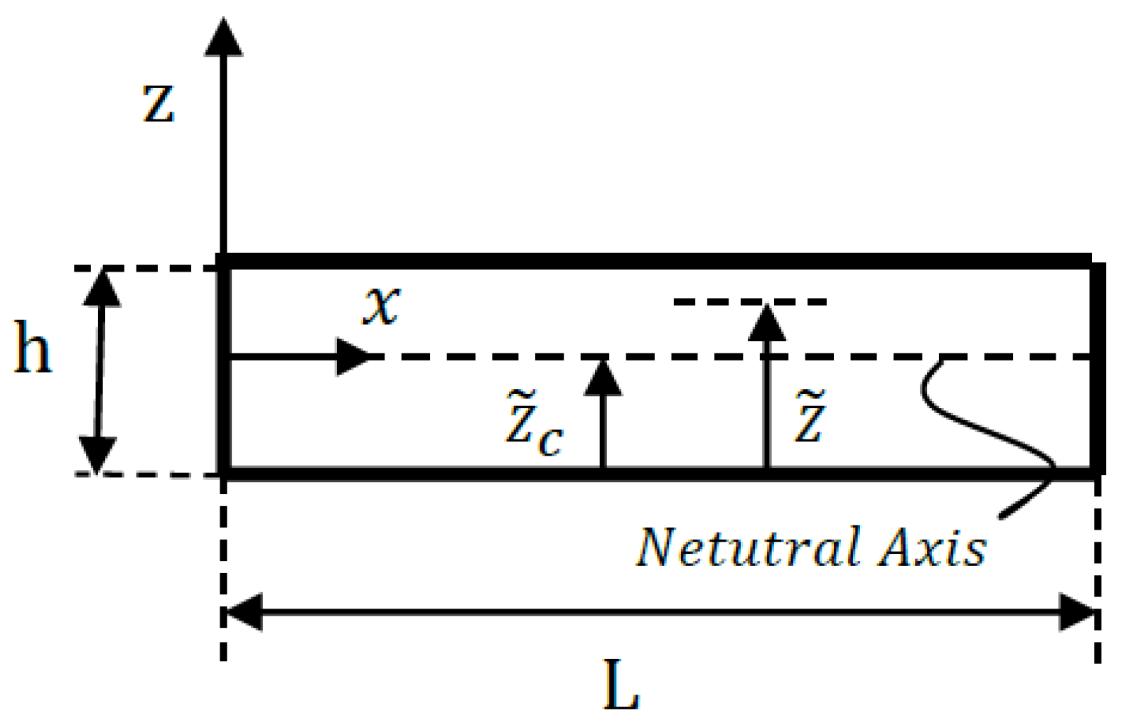
2.1. Formulation of the Problem

Figure 1a,b shows a Euler–Bernoulli beam before and after bending at the presented coordinates. Some assumptions employed in this work were the homogeneity of beam materials and lack of voids and faults within materials and beams. The coordinate system should be as follows: x axis along the length, z axis along the thickness (height), and y axis along the width of the beam. In these theories, the load applied on the beam as well as beam geometry was considered such that ( u 1 , u 2 , u 3 ) displacements, which are displacement elements along x, y and z directions, be only functions of z and x coordinates and time. Then, u 2 , which is displacement along the y axis, was considered to be 0 and governing equations were investigated on the x-z plane. Also, all motion equations of the Euler–Bernoulli beam were presented by the principles of Hamilton and virtual work. Since, the principle of virtual work is independent from structural model, all motion equations which are expressed in terms of stress resultant along the cross-section of the beam were similar for both classical and non-local theories [49,58].
First, stress resultants were defined as:
M = A z σ x x d A N = A σ x x d A
Their displacement fields were defined as:
u 1 = u ( x ^ , t ^ ) + z ψ ( x ^ , t ^ ) , u 2 = 0 ,   u 3 = w ^   ( x ^ , t ^ )
where ( u , w ) are axial and transversal displacements of the beam at point (x,0) in the middle plane (z = 0) of the beam, respectively, W ^ is beam deformation along z direction, and t ^ is time. Also, h, b and L are length, width and thickness, respectively, and ψ is the angles of the rotation of the cross-section of the beam about the y axis, which are:
ψ   ( x ^ , t ^ ) = w ^   x ^
The only non-zero elements of strain in this equation are as follows:
ε x x   = u x ^ z 2 w ^   x ^ 2 ε x x 0 + z κ ,   ε x x 0 = u x ^ ,   κ = 2 w ^ x ^ 2
where ε x x 0 and κ are tensile and bending strains, respectively.
In the element shown in Figure 2, we only needed to write Newtonian equilibrium along the transverse direction of the beam for the length and width of dx. Forces and moments exerted on this element are as shown below.
By calculating forces along z direction and moments along the y direction and coupling the two equations, transversal motion equation is obtained as:
2 M   x ^ 2 + q ^ + x ^ ( N ^ w ^   x ^ ) = m 0 2 w ^     t ^ 2 m 2   4 w ^   x ^ 2 t ^ 2
where ( m 0 ,   m 1 ,   m 2 ) are the mass(rotary) inertias named ( m 0 ,   m 1 ,   m 2 ) = A   ρ ( z ) ( 1 , z , z 2 ) .
It is noteworthy that, if the principle of virtual motion was applied, the above equation would be obtained. In this principle, the following relations would be obtained:
0 = 0 T 0 L [ m 0 ( u t ^ δ u t ^ + w ^   t ^ δ   w ^   t ^ ) + m 2 2 w ^ x ^ t ^ 2 δ w ^ x ^ t ^ + N δ ε x x 0 M δ κ + f δ u + q ^   δ w ^   + N ¯ ^ w ^   x ^ δ w ^   x ^ ] d x ^ d t ^
where f ( x ^ , t ^ ) and q ( x ^ , t ^ ) are axial and lateral distributed forces (force per unit length), respectively, m o is mass per unit length of beam, m 2 is cross-sectional inertia moment in unit length, and N   ¯ ^ is axial force exerted on the beam and its sign is assumed to be in the form of positive tensile.
Based on Euler–Lagrange equations obtained in the range of 0 < x < L, we had:
N x ^ + f = m 0 2 u t ^ 2
2 M   x ^ 2 + q ^ + x ^ (   N ¯ ^ w ^   x ^   ) = m 0 2 w ^     t ^ 2 m 2   4 w ^   x ^ 2 t ^ 2
As can be seen, Equation (8) is similar to Equation (5) but is obtained by the principle of displacement. Unlike, linear algebraic equations between stress resultants and strains in local theory, non-local theory gives differential equations between stress resultants and strains. In the following, the equations are presented based on the assumption that non-local behavior along thickness direction was negligible.

2.2. Governing Differential Equations for Functionally Graded (FG) Beam

In this section, the relations of non-local theory as well as the conditions and properties of a target material (FGM) have been considered. Non-local governing equation was applied, and stress resultant was obtained in terms of strain element.
σ x x μ 2 σ x x x ^ 2 = E ( z ) ε x x
where E is elastic modulus and μ = ( e 0 a ) 2 is the non-local parameter, e 0 is a constant appropriate to each material, a is the internal characteristic length. The non-local parameter depends on the boundary conditions, chirality, mode shapes, number of walls, and type of motion [11]. So far, there is no rigorous study made on estimating the value of the non-local parameter. It is suggested that the value of non-local parameter can be determined by conducting a comparison of dispersion curves from the non-local continuum mechanics and molecular dynamics simulation [17,35,36,37,38,39]. In general, a conservative estimate of the non-local parameter is e 0 a < 2.0 nm for a single wall carbon nanotube [27,30]. Later, some characteristics are obtained from the values used in functional graded beam. The following integrals were calculated separately from the two sides of the Equation (9). To drive force and moment equilibrium equations we need to take the below integrals from both side of Equation (9).
A d A , A z d A
In the above equation, the x axis was considered to pass through the geometric center of beam cross-section along its length. By applying A   d A to Equation (9) we have:
A   σ x x   d A μ   A     2 σ x x x ^ 2 d A = A   E ( z ) ε x x d A N μ 2 N x ^ 2 = A     u x ^ E ( z ) d A A     2 w x ^ 2 z E ( z ) d A
and according to the definition of neutral axis and since coordinate axis (x) is always on neutral axis:
A     E ( z ) z d A = 0
Therefore, the equation of axial strain force was obtained as:
N μ 2 N x 2 = E ( z ) A ε x x 0
Applying A   z d A on Equation (9) gave:
A   z σ x x   d A μ   A     z 2 σ x x x ^ 2 d A = A   E ( z ) z   ε x x d A M μ 2 M x ^ 2 = A     u x ^ E ( z ) z b d z A     2 w x ^ 2 z 2 E ( z ) b d z
where the equations of stress resultant of Euler-Bernoulli beam obtained by solving the differential equations of non-local theory were:
M μ 2 M x ^ 2 = M t   = E   I d 2 W d x 2 = C κ , C = A     z 2 E ( z ) d A = ( E I ) e q
In the above equation, I is second moment of area about y axis. By coupling Equations (7) and (13), axial force motion equations were obtained as:
N = ( E A ) e q u x ^ + μ ( m 0 3 u x ^ t ^ 2 f x ^ ) ( E A ) e q = A E ( z ) d A
Also, by combining Equations (7) and (16), the axial motion equation was obtained as:
x ^ ( ( E A ) e q u x ^ ) + f μ 2 f x ^ 2 = m 0 ( 2 u t ^ 2 μ 4 u x ^ 2 t ^ 2 )
It was also assumed that there is no stimulation along the length of the beam, i.e., the external force exerted on the beam f along the length of the beam was zero. Therefore, u = 0 was the obvious solution of the problem. Hence, in the remainder of the paper, only transversal displacement has been considered.
The second derivative of M from Equation (8) was introduced into Equation (14) and the moment-bending deformation relation was obtained as:
M μ ( m 0 2 w ^     t ^ 2 m 2   4 w ^   x ^ 2 t ^ 2 x ^ ( N ¯ ^ w ^     x ^   ) q ^ ) = C κ  
By combining Equations (8) and (18), overall motion equation for non-local Euler-Bernoulli beam was obtained as:
μ 2 x ^ 2 (   m 0 2 w ^   t ^ 2 m 2   4 w ^   x ^ 2 t ^ 2 x ^ ( N ¯ ^ w ^   x ^   ) q ^ ) C 4 w ^ x ^ 4 = m 0 2 w ^   t ^ 2 m 2   4 w ^   x ^ 2 t ^ 2 q ^ x ^ ( N ¯ ^   w ^   x ^   )
When μ = 0 , motion equations of Euler–Bernoulli beam under classical (local) conditions were obtained. Moving forward, the property of functional graded beam is being employed into the properties of the beam. According to Figure 3, the values of z , z ˜ and z ˜ c are the distance from neutral axis, distance from beam bottom, and the distance of neutral axis from beam bottom, respectively, where
z = z ˜ z ˜ c
As mentioned above, the functional beam power model was used and metal and ceramic were assumed to be aluminum and aluminum oxide, respectively, and the following equations were obtained:
ρ ( z ˜ ) = ρ c + ( z ˜ h ) n ( ρ m ρ c )
E ( z ˜ ) = E c + ( z ˜ h ) n ( E m E c )
m 0 = A ρ ( z ˜ ) d A = 0 h [ ρ c 1 + ( z ˜ h ) n ( ρ m ρ c ) ] b d z ˜ = b h ρ ˜ 0 ( n )
I = m 2 = A ρ ( z ˜ ) z 2 d A = A ρ ( z ˜ ) ( z ˜ z ˜ c ) 2 d A = 0 h ( z ˜ z ˜ c ) 2 [ ρ c + ( z ˜ h ) n ( ρ m ρ c ) ] b d z ˜ = b h 3 ρ ˜ 2 ( n )
C = ( E I ) e q = A E ( z ˜ ) z 2 d A = A E ( z ˜ ) ( z ˜ z ˜ c ) 2 d A = 0 h ( z ˜ z ˜ c ) 2 [ E c + ( z ˜ h ) n ( E m E c ) ] b d z ˜ = b h 3 E ˜ ( n )
where
E ˜ ( n ) = E c 3 + ( E m E c ) n + 3 + ( E c + E m E c n + 1 ) ( E c 2 + E m E c n + 2 E c + E m E c n + 1 ) 2 ( E c + 2 E m E c n + 2 ) E c 2 + E m E c n + 2 E c + E m E c n + 1 ,
ρ ˜ 0 ( n ) = ρ c + ρ m ρ c n + 1
ρ ˜ 2 ( n ) = ρ c 3 + ( ρ m ρ c ) n + 3 + ( ρ c + ρ m ρ c n + 1 ) ( E c 2 + E m E c n + 2 E c + E m E c n + 1 ) 2 ( ρ c + 2 ρ m ρ c n + 2 ) E c 2 + E m E c n + 2 E c + E m E c n + 1 .
In order to determine the position of the beam neutral axis z ˜ c , equilibrium equation along x can be considered as (with reference to Equation (12)): ( z = z ˜ z ˜ c )
A     E ( z ) z d A = A     E ( z ˜ ) z d A = A     E ( z ˜ ) ( z ˜ z ˜ c ) b d z ˜ = 0
z ˜ c = 0 h E ( z ˜ ) z ˜ b d z ˜ 0 h E ( z ˜ ) b d z ˜ = h E c 2 + E m E c n + 2 E c + E m E c n + 1
Coefficients c and m corresponded to ceramic and metal, respectively. Also, the values summarized in Table 1 were considered for the beam. In the case studies, it is assumed that the metal and ceramic phases of the micro-beams are made of aluminum and alumina (aluminum oxide), respectively.

2.3. Dimensionless Governing Equations in Different Boundary Conditions
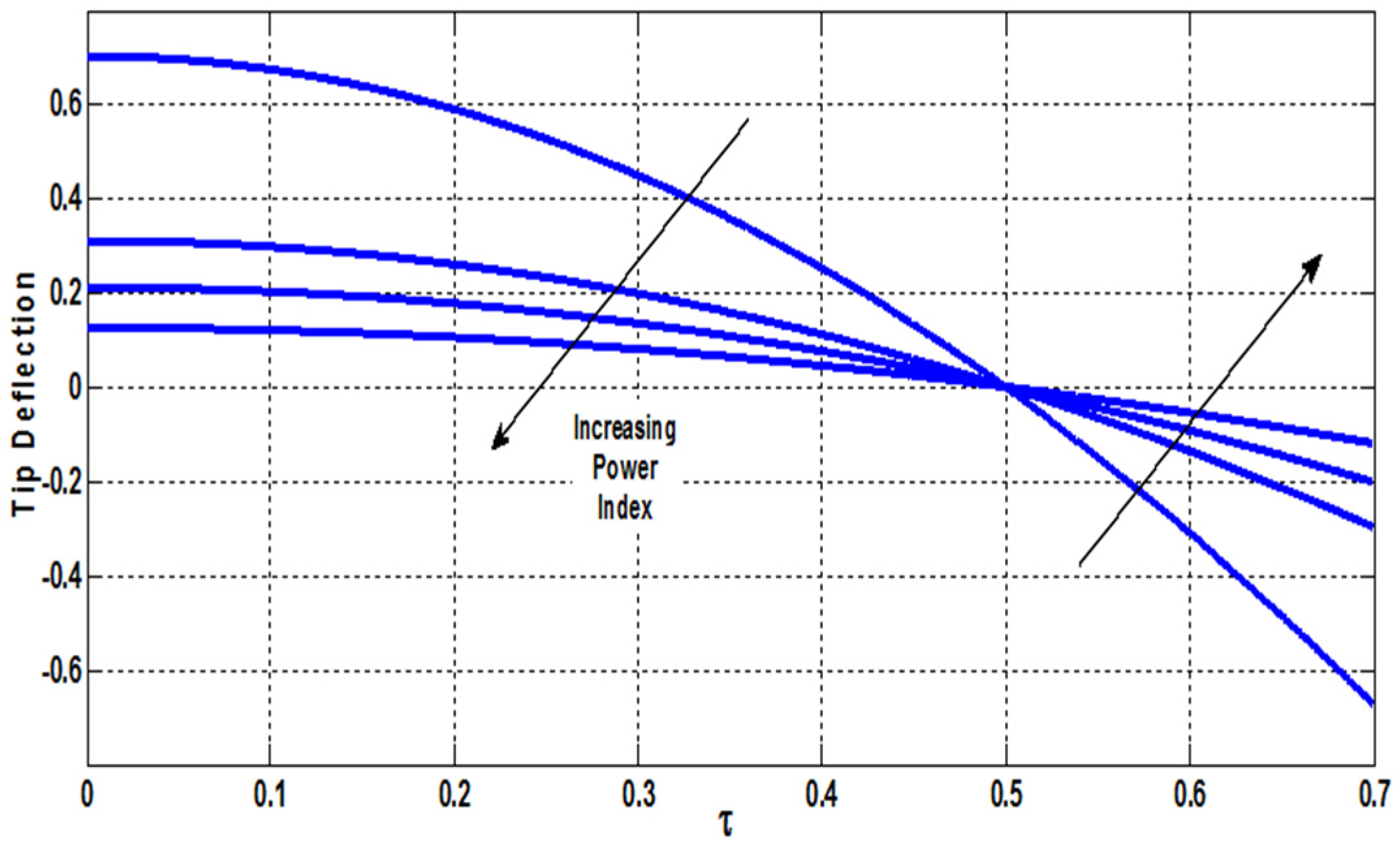
To better investigate the effect of non-locality in this work, motion Equation (18) was made dimensionless by introducing the following parameters:
α τ 2 6 w x 4 t 2 ( α + τ 2 ) 4 w x 2 t 2 + ( β + N τ 2 ) 4 w x 4 N 2 w x 2 + 2 w t 2 + τ 2 2 q x 2 q = 0
where
x = x ^ l , w = w ^ l , t = t ^ T , N = N ¯ ^ N ˜ , q = q ^ q ˜
T = l 2 m 0 C c , N ˜ = C c l 2 , q ˜ = C c l 3 , τ 2 = μ l 2 , α = m 2 m 0 l 2 , β = C C c
where C and C c are ( E I ) e q for functional beam and ceramic, respectively, α and β are parameters which remain in equations after becoming dimensionless. They will hold identity of functional graded materials and, and τ has the nature of non-local theory.
Since the principle of Hamilton is independent from the presented structural model, stress resultants were introduced in terms of generalized coordinates. Therefore, the presentation of the principle of Hamilton was also based on this coordinate and was the same for both classical and non-local theories.
Using the principle of Hamilton in the Euler–Bernoulli beam we had:
δ t 1 t 2 ( T U + W ) d t = 0 0 = 0 T 0 L { m 0 ( w ^ t ^ δ w ^ t ^ ) + m 2 2 w ^ x ^ t ^ 2 δ w ^ x ^ t ^ + q ^ δ w ^ ( E I ) e q 2 w ^ x ^ 2 2 δ w ^ x ^ 2 + N ¯ ^ δ w ^ x ^ δ w ^ t ^ + μ [ x ^ ( N ¯ ^ δ w ^ x ^ ) q ^ + m 0 2 w ^ t ^ 2 m 2 4 w ^ x ^ 2 t ^ 2 ] 2 δ w ^ x ^ 2 } d x ^ d t ^ + 0 T [ V δ w ^ M δ w ^ x ^ ] L 0   d t ^
where V is equivalent shear force. The equations extracted from variational terms were verified since they were similar to those extracted from Euler–Lagrange equations. Boundary conditions at x = 0 , L were also obtained.
V = m 2 3 w ^ x ^   t ^ 2 + N ¯ ^ δ w ^ x ^ x ^ ( ( E I ) e q 2 w ^ x ^ 2 ) + μ x ^ [ m 0 2 w ^   t ^ 2 m 2   4 w ^   x ^ 2 t ^ 2 x ^ ( N ¯ ^ w ^   x ^   ) q ^ ] M = ( E I ) e q 2 w ^ x ^ 2 + μ [ m 0 2 w ^   t ^ 2 m 2   4 w ^   x ^ 2 t ^ 2 x ^ ( N ¯ ^ w ^   x ^   ) q ^ ]
If the obtained V and M were made dimensionless, we had:
V ( x ) = C c l 2 ( ( ( α + τ 2 ) ω 2 N ) W ( x ) + ( β τ 2 ( α ω 2 N ) ) W ( x ) + τ 2 q ) M ( x ) = C c l ( ( β τ 2 ( α ω 2 N ) ) W ( x ) + τ 2 ω 2 W ( x ) + τ 2 q )
where ‘, ’’, and ’’’ refer to first and second and third derivative of x, respectively.

3. Static Analysis

Due to the wide applications and popularity of beams with one free end (cantilever), especially in actuators, this boundary condition has been evaluated in this section. Since we know that under static analysis conditions there is no time dependency, the governing Equation (30) was simplified as:
( β + N τ 2 ) W ( 4 ) + ( N ) W + τ 2 2 q x 2 q = 0
Under this condition, since time term is eliminated, using Equation (33) boundary conditions for cantilever beam is changed and new accurate conditions for the end is considered as:
V ( x ) = C c l 2 ( ( N ) W ( x ) + ( β + τ 2 N ) W ( x ) + τ 2 q )
M ( x ) = C c l ( ( β + τ 2 N ) W ( x ) + τ 2 q )
To solve the static governing equation, first transversal load q was applied in two different forms of point and uniform loads onto functional beam and then the problem was solved.For point loading fixed at the beam end by assuming q = 0 ,   q ( 1 ) = P 0 ,   N = 0 , equation and boundary conditions were obtained as:
( β ) W ( 4 ) = 0 , W ( 0 ) = W ( 0 ) = 0 , V ( 1 ) = P 0 , M ( 1 ) = 0 , V ( 1 ) = ( β ) W ( 1 ) = P 0
M ( 1 ) = W ( 1 ) = 0
W ( x ) = P 0 6 β ( 3 x 2 x 3 )
where the obtained equation gave similar results to local theory and no effect of non-local parameter was observed. When the location of point load was assumed to be variable as x = Ω ,   0 < Ω < 1 , the solution was:
W ( x ) = P 0 6 β   { x 2 ( 3 Ω x ) x < Ω Ω 2 ( 3 x Ω ) x > Ω
which shows that even under these conditions, non-local theory did not have any effects. Therefore, in cantilever beams, point loads gave similar results in classical and non-classical theories regardless of their location.
It is obvious that, since β varies between 0 and 1, its effect is evident in the increase and decrease of beam deflection. Since here we had 0.1781 < β < 1 , its main effect was in the increase of beam rise. For uniform load, by assuming q = p 0 ,   N = 0 , equation and boundary conditions were obtained as:
( β ) W ( 4 ) + τ 2 2 q x 2 q = 0
W ( 0 ) = W ( 0 ) = 0 , M ( 1 ) = 0 , V ( 1 ) = 0
W ( x ) = p 0 24 β x 2 ( x 2 4 x + 6 ( 1 2 τ 2 ) )
Under these conditions, unlike the previous one in which concentrated force was applied and only the effects of functional materials were considered significant, the effect of non-local theory was also observed. Non-local continuum field theory manages the physics of material bodies in which behavior at a material point is affected by the state of all points of the body
As was seen in Figure 4, increasing of non-local parameter lessens the deflection of beam tip and, compared to classical theory, deflection is at least halved (infinity power index). It can be seen in the diagram that at τ = 0.5 beam tip deflection becomes 0 which was also obtained by Paddison [7]. As mentioned above, at τ > 0.5 (τ = 0.5 is zero reference for beam tip deflection), the direction of beam deflection is inversed which could be problematic; therefore, it should be noted that if, for example, positive direction of deflection is under investigation, we can use values of up to τ < 0.5. Therefore, the effect of the variation of the non-local parameter was obviously observed.
Regarding the effect of FG materials, it was also observed that by increasing the power index from 0, i.e., pure metal, to infinity, i.e., ceramic, beam tip deflection was decreased not only before but also after τ = 0.5 . Therefore, it was observed that if high deflections were required in designing actuators, power indices should be very close to 0 and if low deflection and actuation were required, values such as 1, 2, 3, etc. should be addressed so that the material could retain its functional properties. If δ was the highest deformation (x = 1) in non-local theory and δ 0 was the highest deformation (x = 1) in classical theory, their ratios were:
δ δ 0 = 1 4 τ 2 , τ = e 0 a L
If it as assumed that non-local error was 1% and by considering the approximate value of 0.4 for e 0 , the following condition have to be created [7]:
L a > 8
Also, we know that microelectromechanical cantilever actuators were almost 100–500 µm long ( 1 × 10 4   m < L < 5 × 10 4   m ) and atomic distances or the distance between adjacent crystals were in the range of angstroms ( 1 × 10 10   m < a < 1 × 10 9   m ) . Therefore, non-local theory could not have a significant effect on micro-electromechanical system (MEMS). The recommended systems or devices in nanotechnology had dimensions in the scale of ( 1 × 10 9   m < L < 1 × 10 8   m ) but it is clear that the effect of non-local theory becomes significant at nanoscale. Therefore, we investigated the problem in this work for a beam L = 20 nm in length to make the effects more significant.

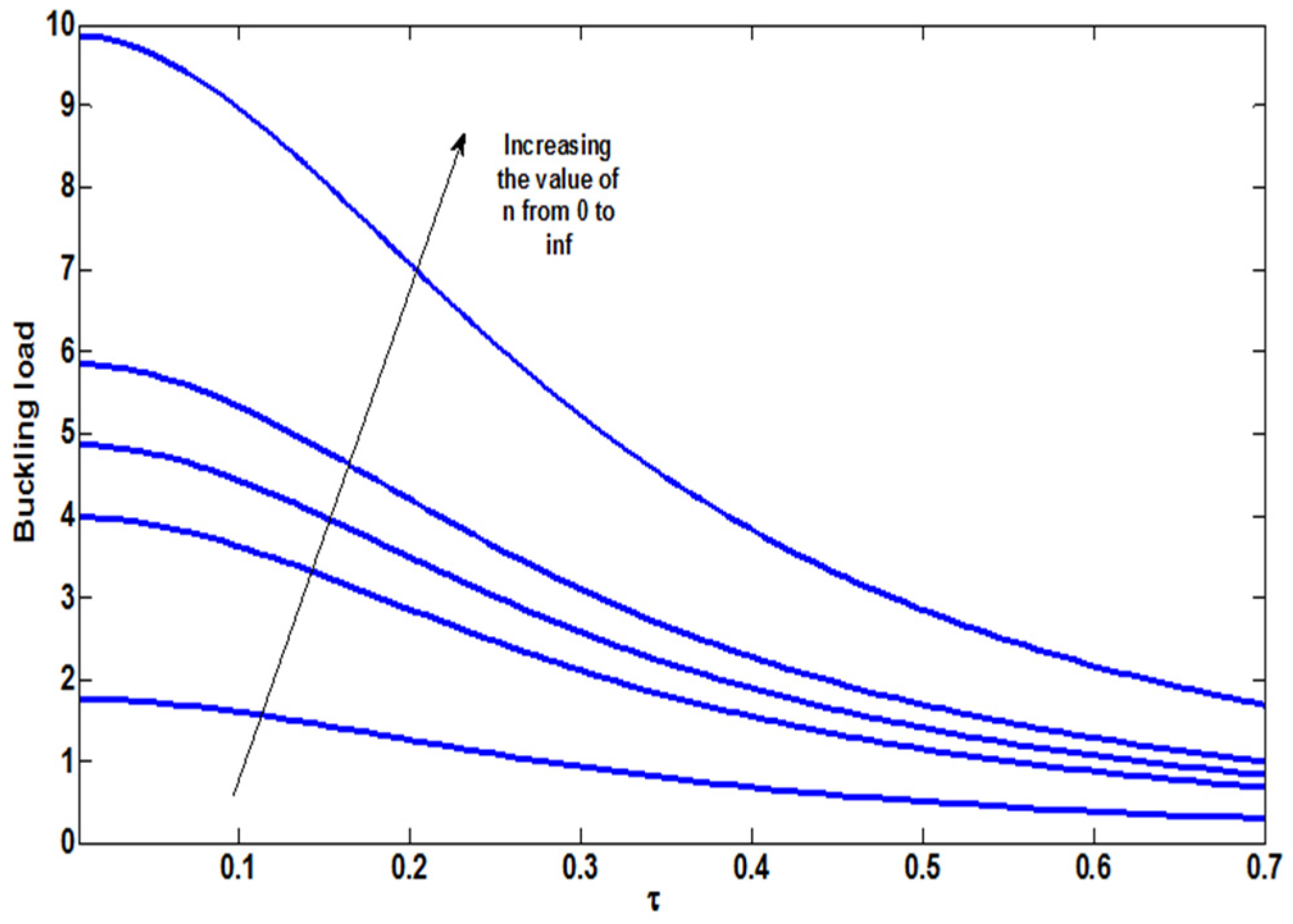
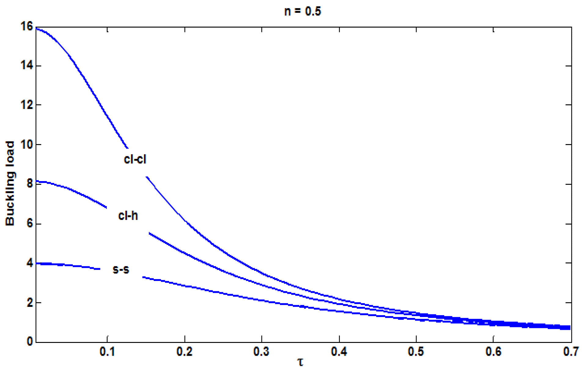
4. Buckling Analysis

As known, in thin and long beams and columns, like Euler–Bernoulli beams, the importance of buckling failure generally overrides over that of yield failure. Thus, in this section, the values of critical buckling for different boundary conditions have been investigated. For the calculation of critical buckling load with Equation (30), q and all-time derivatives have to be considered to be zero, then we have:
( β N τ 2 ) W ( 4 ) + N W = 0
By solving this normal differential equation, we obtained particular and general solutions as:
W = C 1 + C 2 x + C 3 c o s k x + C 4 s i n k x
in which, by applying different boundary conditions, unknown coefficients ( C 1 , C 2 , C 3   a n d   C 4 ) were obtained, and k is obtained by solving the characteristic equation and, therefore, critical force was calculated, also Table 2 gives different values of k per its specific BCs.
k 2 = N β N τ 2
N c r = k 2 β ( 1 + k 2 τ 2 )
Figure 5 shows the effect of non-local parameter on critical buckling load for different power values in a simply-supported ends beam. It was seen that non-local parameter significantly decreased buckling in beams regardless of their material. For other boundary conditions also, the values were similarly decreased. By increasing power index toward infinity, buckling load was also increased; in other words, by increasing the volume fraction of metal, buckling load becomes lower. Figure 6 shows the effect of the non-local parameter on critical load for different boundary conditions for n = 0.5. As expected, critical load was s s < s c l < c l c l . Also, it was seen from the figure that at τ = 0 , the values were increased at certain ratio of 2 which is the ratio found by Fernand Bear et al. [59] for classical conditions. At high values of non-local parameter, buckling loads for all BCs become closer together because n was constant and the value of k 2 was very higher than 1 in the denominator; therefore, at high values of τ , buckling load tends toward β τ 2 which was independent of boundary condition.

5. Dynamic Analysis

In this section, the problem has been solved considering transversal force on the beam. The motion equation of a beam under transversal load are as follows. Load P at velocity v 0 was moved on the beam. If transversal force was assumed as a moving load, as shown in Figure 7:
Using the method of modes summation (modal analysis), the assumed solution of Equation (30) was a linear combination of normal modes of the beam as:
w ( x , t ) = i = 1 η i ( t ) ϕ i ( x )
where ϕ i ( x ) is normal mode which was obtained by solving free vibrations under different boundary conditions and η i ( t ) is the generalized coordinates of modal contribution coefficient. By substituting Equation (46) into Equation (30) we obtained:
α τ 2 η ¨ i ϕ i ( α + τ 2 ) η ¨ i ϕ i + η i ( β + N τ 2 ) ϕ i N η i ϕ i + η ¨ i ϕ i   + τ 2 2 q x 2 q = 0
in which force was applied to the beam as a delta function; q = P δ ( x v 0 t ) . By substituting force into Equation (47) we had:
α τ 2 η ¨ i ϕ i ( α + τ 2 ) η ¨ i ϕ i + η i ( β + N τ 2 ) ϕ i N η i ϕ i + η ¨ i ϕ i   + τ 2 P ( δ ( x v 0 t ) ) P δ ( x v 0 t ) = 0
Then, based on the method of summation of modes, the two sides of above equation were multiplied by ϕ i and integrated from 0 to 1 which gave:
α τ 2 η ¨ i 0 1 ϕ i ϕ i d x ( α + τ 2 ) η ¨ i 0 1 ϕ i ϕ i d x + η i ( β + N τ 2 ) 0 1 ϕ i ϕ i d x N η i 0 1 ϕ i ϕ i d x + η ¨ i 0 1 ϕ i 2 d x = P 0 1 ϕ i δ ( x v 0 t ) d x τ 2 P 0 1 ϕ i ( δ ( x v 0 t ) ) d x
Using perpendicular modes, which was considered for the first three modes in this work, the following differential equation was obtained in terms of η .
( α τ 2 A + C B ( α + τ 2 ) )   η ¨ i ( t ) ( N B ( β + N τ 2 ) A ) η i ( t ) = Q i ( t )
A = 0 1 ϕ i ϕ i d x ,   B = 0 1 ϕ i ϕ i d x ,   C = 0 1 ϕ i 2 d x Q i ( t ) = 0 1 ϕ i q ( x , t ) d x = P ( ϕ i ( v 0 t ) τ 2 ϕ i ( v 0 t ) )
Using Equations (50) and (51) we had:
η ¨ i ( t ) ( N B ( β + N τ 2 ) A ) ( α τ 2 A + C B ( α + τ 2 ) ) η i ( t ) = P ( α τ 2 A + C B ( α + τ 2 ) ) [ A 1 ( 1 τ 2 s 1 2 ) c o s h s 1 v t + A 2 ( 1 τ 2 s 1 2 ) s i n h s 1 v t + B 1 ( 1 + τ 2 s 2 2 ) c o s s 2 v t + B 2 ( 1 + τ 2 s 2 2 ) s i n s 2 v t ]
The solution of the equation was:
η i = P A 1 ( 1 τ 2 s 1 2 ) J + s 1 2 v 2 c o s h s 1 v t + P A 2 ( 1 τ 2 s 1 2 ) J + s 1 2 v 2 s i n h s 1 v t + P B 1 ( 1 + τ 2 s 2 2 ) J s 2 2 v 2 c o s s 2 v t + P B 2 ( 1 + τ 2 s 2 2 ) J s 2 2 v 2 s i n s 2 v t + D s i n ( ω t + )
where
J = ( ( β + N τ 2 ) A N B ) ( α τ 2 A + C B ( α + τ 2 ) ) s 1 = b + b 2 4 ac 2 a ، s 2 = b + b 2 4 ac 2 a a = ( β + ( N α ω 2 ) τ 2 ) , b = ( ( α + τ 2 ) ω 2 N ) , c = ω 2
in which the application of primary conditions of beam gave:
η i ( 0 ) = P A 1 ( 1 τ 2 s 1 2 ) J + s 1 2 v 2 + P B 1 ( 1 + τ 2 s 2 2 ) J s 2 2 v 2 + D s i n ( ) = 0 η i ( 0 ) = P A 2 s 1 v ( 1 τ 2 s 1 2 ) J + s 1 2 v 2 + P B 2 s 2 v ( 1 + τ 2 s 2 2 ) J s 2 2 v 2 + D ω cos ( ) = 0
By solving the two above equations, the two unknowns and D were obtained.
Figure 8 shows the beam deformation at applied load location in Cl-Cl and cantilever beams for the three first modes with the variation of the power index under a constant non-local parameter. As seen in the figure, increase of functional material coefficient, diagram peaks which were obtained at critical velocity are shifted forward. Peaks are points where critical velocity (resonance frequency) occurred and since there is no damping in the system, their values tend toward infinite. At high values of non-local parameters, the peaks become close to each other for any power index, velocities (resonance frequency) become smaller, and the appropriate (safe) range for adopting velocity was increased. Therefore, coefficient n, as a design parameter, should be adopted such that the velocity of applied load be at reasonable magnitude order (generally 10%) from critical velocity. It is noteworthy that we considered only three modes and too many other modes existed. The assumption of three modes is almost correct although other modes do not have significant effects. In Figure 8, it can be seen that at velocity zero, which was static condition, an increase of FG coefficient of the material increases its stiffness resulting in lower deformation. These results were also discussed in static section. In Figure 9, a cl-cl beam with constant power index was used to evaluate the effect of the non-local parameter on velocity and deformation and it was found that the increase of the non-local parameter reduces the velocity value and unsafe range (peaks became closer). Since the stiffness of beam was decreased (decrease of frequency) deformation increased under both dynamic and static conditions.
In Figure 10, a cantilever beam was used to demonstrate beam tip deformation versus the velocity of applied load for the variation of the power index of functional material under constant non-local parameter value. Like cl-cl beams, these diagrams also provided almost similar results, but the convergence of critical velocities was slower. Here, the critical velocities of second and third modes converged and then they got closer to the velocity of the first mode. Figure 11 shows the behavior of FG material with a certain power index for different non-local parameters. Unlike Figure 10 for cl-cl beams, in this diagram, at velocity 0 (static condition) increase of non-local effect decreased beam deformation, although this increase was not significant. It was seen from the figures that non-local effect was negligible in the first mode. Like cl-cl beams, dynamic deformations in this figure were increased by the increase of this effect and the differences observed in this figure compared to Figure 9 were due to the increase of the first frequency in the cantilever beam.

6. Conclusions

Here, we have established the boundary conditions and governing equations of FG Euler–Bernoulli beams using the non-local theory of elasticity. Then, free vibrations were studied and the effects of the non-local parameter, power index and axial load on the natural frequencies of s-s beams were assessed. The results obtained indicated that the non-local parameter decreased the frequency while the power index increased it. However, the inverse results were obtained for the cantilever beam, particularly for the first natural frequency. Axial load was also observed to increase the frequency value. Static and buckling analysis were done to show how micro/nano beams behave under two different types of load and it was shown that non-local theory is more capable of showing its influence in nano scale than micro. Dynamic analysis was examined under a moving load for the first three mode shapes. Power index was shown to be a strong tool for determining the coefficient of the critical velocity and oscillation domain. The location of these critical velocities (peaks) helped us in the design of the dynamic load.

Author Contributions

R.M. developed and executed the research study and wrote the initial manuscript. H.D. supervised the findings of this work and helped with the modified write-up. All authors contributed to the final manuscript writing and discussed the results. All authors have read and agreed to the published version of the manuscript.

Funding

This research received no external funding.

Conflicts of Interest

The authors declare no conflict of interest.

References

  1. Li, C.; Yao, L.; Chen, W.; Li, S. Comments on nonlocal effects in nano-cantilever beams. Int. J. Eng. Sci. 2015, 87, 47–57. [Google Scholar] [CrossRef]
  2. Fallah, A.; Firoozbakhsh, K.; Pasharavesh, A. Nonlinear Thermo-Mechanical Vibration Analysis of Functionally Graded Beams. In Proceedings of the ASME 2011 International Design Engineering Technical Conferences and Computers and Information in Engineering Conference, Washington, DC, USA, 28–31 August 2011; pp. 787–792. [Google Scholar]
  3. Reddy, J. Nonlocal nonlinear formulations for bending of classical and shear deformation theories of beams and plates. Int. J. Eng. Sci. 2010, 48, 1507–1518. [Google Scholar] [CrossRef]
  4. Reddy, J. Nonlocal theories for bending, buckling and vibration of beams. Int. J. Eng. Sci. 2007, 45, 288–307. [Google Scholar] [CrossRef]
  5. Şimşek, M.; Yurtcu, H. Analytical solutions for bending and buckling of functionally graded nanobeams based on the nonlocal Timoshenko beam theory. Compos. Struct. 2013, 97, 378–386. [Google Scholar] [CrossRef]
  6. Thai, H.-T. A nonlocal beam theory for bending, buckling, and vibration of nanobeams. Int. J. Eng. Sci. 2012, 52, 56–64. [Google Scholar] [CrossRef]
  7. Peddieson, J.; Buchanan, G.R.; McNitt, R.P. Application of nonlocal continuum models to nanotechnology. Int. J. Eng. Sci. 2003, 41, 305–312. [Google Scholar] [CrossRef]
  8. Ruocco, E.; Zhang, H.; Wang, C. Buckling and vibration analysis of nonlocal axially functionally graded nanobeams based on Hencky-bar chain model. Appl. Math. Model. 2018, 63, 445–463. [Google Scholar] [CrossRef] [Green Version]
  9. Qin, Z.; Zhao, S.; Pang, X.; Safaei, B.; Chu, F. A unified solution for vibration analysis of laminated functionally graded shallow shells reinforced by graphene with general boundary conditions. Int. J. Mech. Sci. 2020, 170, 105341. [Google Scholar] [CrossRef]
  10. Romano, G.; Barretta, R.; Diaco, M.; De Sciarra, F.M. Constitutive boundary conditions and paradoxes in nonlocal elastic nanobeams. Int. J. Mech. Sci. 2017, 121, 151–156. [Google Scholar] [CrossRef]
  11. Arash, B.; Wang, Q. A review on the application of nonlocal elastic models in modeling of carbon nanotubes and graphines. Comput. Mat. Sci. 2012, 51, 303–313. [Google Scholar] [CrossRef]
  12. Safaei, B.; Khoda, F.H.; Fattahi, A.M. Non-classical plate model for single-layered graphene sheet for axial buckling. Adv. Nano Res. 2019, 7, 265–275. [Google Scholar]
  13. Birman, V.; Byrd, L.W. Modeling and Analysis of Functionally Graded Materials and Structures. Appl. Mech. Rev. 2007, 60, 195–216. [Google Scholar] [CrossRef]
  14. Pasharavesh, A.; Zohoor, H.; Ahmadian, M.T. On the energy extraction from large amplitude vibrations of MEMS-based piezoelectric harvesters. Acta Mech. 2017, 228, 3445–3468. [Google Scholar] [CrossRef]
  15. Pasharavesh, A.; Zohoor, H.; Ahmadian, M.T. Electromechanical modeling and analytical investigation of nonlinearities in energy harvesting piezoelectric beams. Int. J. Mech. Mater. Des. 2016, 13, 499–514. [Google Scholar] [CrossRef]
  16. Pasharavesh, A.; Ahmadian, M.T. Analytical and numerical simulations of energy harvesting using MEMS devices operating in nonlinear regime. Eur. Phys. J. B 2018, 91, 241. [Google Scholar] [CrossRef]
  17. Arash, B.; Ansari, R. Evaluation of nonlocal parameter in the vibrations of single-walled carbon nanotubes with initial strain. Phys. E Low Dimens. Syst. Nanostruct. 2010, 42, 2058–2064. [Google Scholar] [CrossRef]
  18. Zhang, B.; He, Y.; Liu, D.; Gan, Z.; Shen, L. Size-dependent functionally graded beam model based on an improved third-order shear deformation theory. Eur. J. Mech. A Solids 2014, 47, 211–230. [Google Scholar] [CrossRef]
  19. Li, L.; Hu, Y. Nonlinear bending and free vibration analyses of nonlocal strain gradient beams made of functionally graded material. Int. J. Eng. Sci. 2016, 107, 77–97. [Google Scholar] [CrossRef]
  20. Eptaimeros, K.; Koutsoumaris, C.; Dernikas, I.; Zisis, T. Dynamical response of an embedded nanobeam by using nonlocal integral stress models. Compos. Part B Eng. 2018, 150, 255–268. [Google Scholar] [CrossRef]
  21. Simsek, M. Nonlinear free vibration of a functionally graded nanobeam using nonlocal strain gradient theory and a novel Hamiltonian approach. Int. J. Eng. Sci. 2016, 105, 12–27. [Google Scholar] [CrossRef]
  22. Pasharavesh, A.; Ahmadian, M.T.; Zohoor, H. Coupled electromechanical analysis of MEMS-based energy harvesters integrated with nonlinear power extraction circuits. Microsyst. Technol. 2016, 23, 2403–2420. [Google Scholar] [CrossRef]
  23. Pasharavesh, A.; Moheimani, R.; Dalir, H. Performance Analysis of an Electromagnetically Coupled Piezoelectric Energy Scavenger. Energies 2020, 13, 845. [Google Scholar] [CrossRef] [Green Version]
  24. Pasharavesh, A.; Vaghasloo, Y.A.; Ahmadian, M.T.; Moheimani, R. Nonlinear Vibration Analysis of Nano to Micron Scale Beams Under Electric Force Using Nonlocal Theory. In Proceedings of the ASME 2011 International Design Engineering Technical Conferences and Computers and Information in Engineering Conference, Washington, DC, USA, 28–31 August 2011; pp. 145–151. [Google Scholar]
  25. Sahmani, S.; Safaei, B. Nonlinear free vibrations of bi-directional functionally graded micro/nano-beams including nonlocal stress and microstructural strain gradient size effects. Thin Walled Struct. 2019, 140, 342–356. [Google Scholar] [CrossRef]
  26. Sahmani, S.; Safaei, B. Nonlocal strain gradient nonlinear resonance of bi-directional functionally graded composite micro/nano-beams under periodic soft excitation. Thin Walled Struct. 2019, 143, 106226. [Google Scholar] [CrossRef]
  27. Vaghasloo, Y.A.; Pasharavesh, A.; Ahmadian, M.T.; Fallah, A. Static Analysis of Electrically Actuated Nano to Micron Scale Beams Using Nonlocal Theory. In Proceedings of the ASME 2011 International Design Engineering Technical Conferences and Computers and Information in Engineering Conference, Washington, DC, USA, 28–31 August 2011; pp. 391–396. [Google Scholar]
  28. Fattahi, A.M.; Safaei, B.; Ahmed, N.A. A comparison for the non-classical plate model based on axial buckling of single-layered graphene sheets. Eur. Phys. J. Plus 2019, 134, 555. [Google Scholar] [CrossRef]
  29. De Sciarra, F.M.; Barretta, R. A new nonlocal bending model for Euler–Bernoulli nanobeams. Mech. Res. Commun. 2014, 62, 25–30. [Google Scholar] [CrossRef]
  30. Wang, Q.; Liew, K.M. Application of nonlocal continuum mechanics to static analysis of micro- and nano-structures. Phys. Lett. A 2007, 363, 236–242. [Google Scholar] [CrossRef]
  31. Sahmani, S.; Safaei, B. Influence of homogenization models on size-dependent nonlinear bending and postbuckling of bi-directional functionally graded micro/nano-beams. Appl. Math. Model. 2020, 82, 336–358. [Google Scholar] [CrossRef]
  32. Yuan, Y.; Zhao, K.; Sahmani, S.; Safaei, B. Size-dependent shear buckling response of FGM skew nanoplates modeled via different homogenization schemes. Appl. Math. Mech. 2020, 1–18. [Google Scholar] [CrossRef]
  33. Yang, X.; Sahmani, S.; Safaei, B. Postbuckling analysis of hydrostatic pressurized FGM microsized shells including strain gradient and stress-driven nonlocal effects. Eng. Comput. 2020, 119, 1–16. [Google Scholar] [CrossRef]
  34. Taati, E. Analytical solutions for the size dependent buckling and postbuckling behavior of functionally graded micro-plates. Int. J. Eng. Sci. 2016, 100, 45–60. [Google Scholar] [CrossRef]
  35. Eringen, A. Nonlocal polar elastic continua. Int. J. Eng. Sci. 1972, 10, 1–16. [Google Scholar] [CrossRef]
  36. Eringen, A.C. On differential equations of nonlocal elasticity and solutions of screw dislocation and surface waves. J. Appl. Phys. 1983, 54, 4703. [Google Scholar] [CrossRef]
  37. Eringen, A.; Wegner, J. Nonlocal Continuum Field Theories. Appl. Mech. Rev. 2003, 56, B20–B22. [Google Scholar] [CrossRef]
  38. Eringen, A.C.; Edelen, D.G.B. On nonlocal elasticity. Int. J. Eng. Sci. 1972, 10, 233–248. [Google Scholar] [CrossRef]
  39. Wang, C.; Zhang, Y.; Ramesh, S.S.; Kitipornchai, S. Buckling analysis of micro- and nano-rods/tubes based on nonlocal Timoshenko beam theory. J. Phys. D Appl. Phys. 2006, 39, 3904–3909. [Google Scholar] [CrossRef]
  40. Nejad, M.Z.; Hadi, A.; Rastgoo, A. Buckling analysis of arbitrary two-directional functionally graded Euler–Bernoulli nano-beams based on nonlocal elasticity theory. Int. J. Eng. Sci. 2016, 103, 1–10. [Google Scholar] [CrossRef]
  41. Chakraverty, S.; Behera, L. Buckling analysis of nanobeams with exponentially varying stiffness by differential quadrature method. Chin. Phys. B 2017, 26, 74602. [Google Scholar] [CrossRef]
  42. Rahmani, O.; Hosseini, S.A.; Parhizkari, M. Buckling of double functionally-graded nanobeam system under axial load based on nonlocal theory: An analytical approach. Microsyst. Technol. 2016, 23, 2739–2751. [Google Scholar] [CrossRef]
  43. Li, X.; Li, L.; Hu, Y.; Ding, Z.; Deng, W. Bending, buckling and vibration of axially functionally graded beams based on nonlocal strain gradient theory. Compos. Struct. 2017, 165, 250–265. [Google Scholar] [CrossRef]
  44. Murmu, T.; Pradhan, S. Buckling analysis of a single-walled carbon nanotube embedded in an elastic medium based on nonlocal elasticity and Timoshenko beam theory and using DQM. Phys. E Low Dimens. Syst. Nanostruct. 2009, 41, 1232–1239. [Google Scholar] [CrossRef]
  45. Ahmadian, M.T.; Pasharavesh, A.; Fallah, A. Application of Nonlocal Theory in Dynamic Pull-In Analysis of Electrostatically Actuated Micro and Nano Beams. In Proceedings of the International Design Engineering Technical Conferences and Computers and Information in Engineering Conference, Washington, DC, USA, 28–31 August 2011; pp. 255–261. [Google Scholar]
  46. Shahba, A.; Attarnejad, R.; Marvi, M.T.; Hajilar, S. Free vibration and stability analysis of axially functionally graded tapered Timoshenko beams with classical and non-classical boundary conditions. Compos. Part B Eng. 2011, 42, 801–808. [Google Scholar] [CrossRef]
  47. Huang, Y.; Zhang, M.; Rong, H. Buckling Analysis of Axially Functionally Graded and Non-Uniform Beams Based on Timoshenko Theory. Acta Mech. Solida Sin. 2016, 29, 200–207. [Google Scholar] [CrossRef]
  48. Sahraee, S.; Saidi, A.R. Free vibration and buckling analysis of functionally graded deep beam-columns on two-parameter elastic foundations using the differential quadrature method. Proc. Inst. Mech. Eng. Part C J. Mech. Eng. Sci. 2009, 223, 1273–1284. [Google Scholar] [CrossRef]
  49. Deng, H.; Chen, K.; Cheng, W.; Zhao, S. Vibration and buckling analysis of double-functionally graded Timoshenko beam system on Winkler-Pasternak elastic foundation. Compos. Struct. 2017, 160, 152–168. [Google Scholar] [CrossRef]
  50. Eringen, A.C. Theory of micropolar plates. Z. für Angew. Math. Phys. ZAMP 1967, 18, 12–30. [Google Scholar] [CrossRef]
  51. Gurtin, M.E.; Weissmüller, J.; Larché, F. A general theory of curved deformable interfaces in solids at equilibrium. Philos. Mag. A 1998, 78, 1093–1109. [Google Scholar] [CrossRef]
  52. Pasharavesh, A.; Ahmadian, M.T. Toward Wideband Piezoelectric Harvesters Through Self-Powered Transitions to High-Energy Response. J. Vib. Acoust. 2019, 142, 1–28. [Google Scholar] [CrossRef]
  53. Fattahi, A.M.; Safaei, B.; Moaddab, E. The application of nonlocal elasticity to determine vibrational behavior of FG nanoplates. Steel Compos. Struct. 2019, 32, 281–292. [Google Scholar]
  54. El-Borgi, S.; Rajendran, P.; Friswell, M.; Trabelssi, M.; Reddy, J. Torsional vibration of size-dependent viscoelastic rods using nonlocal strain and velocity gradient theory. Compos. Struct. 2018, 186, 274–292. [Google Scholar] [CrossRef] [Green Version]
  55. Moheimani, R.; Pasharavesh, A.; Dalir, H. The effect of finite electrical conductivity of small-scale beam resonators on their vibrational response under electrostatic fields. Int. J. Mech. Mater. Des. 2020, 1–14. [Google Scholar] [CrossRef]
  56. Ma, L.; Ke, L.-L.; Reddy, J.; Yang, J.; Kitipornchai, S.; Wang, K. Wave propagation characteristics in magneto-electro-elastic nanoshells using nonlocal strain gradient theory. Compos. Struct. 2018, 199, 10–23. [Google Scholar] [CrossRef]
  57. Apuzzo, A.; Barretta, R.; Faghidian, S.A.; Luciano, R.; De Sciarra, F.M. Free vibrations of elastic beams by modified nonlocal strain gradient theory. Int. J. Eng. Sci. 2018, 133, 99–108. [Google Scholar] [CrossRef]
  58. Moheimani, R.; Ahmadian, M.T. On Free Vibration of Functionally Graded Euler-Bernoulli Beam Models Based on the Non-Local Theory. In Proceedings of the ASME 2012 International Mechanical Engineering Congress and Exposition, Houston, TX, USA, 9–15 November 2012; pp. 169–173. [Google Scholar]
  59. Beer, F.P.; Johnston, E.R.; Dewoll, J.T. Mechanics of Materials, 3rd ed.; Prentice-Hall International: Upper Saddle River, NJ, USA, 2002. [Google Scholar]
Figure 1. Schematic diagram of a Euler–Bernoulli beam before (a) and after (b) bending in coordinate system.
Vibration 03 00006 g001
Figure 2. Beam element and forces and moments applied on it.
Vibration 03 00006 g002
Figure 3. Schematic diagram of a Euler–Bernoulli functionally graded material (FGM) micro-beam.
Vibration 03 00006 g003
Figure 4. Non-local effect on the tip displacement of the beam with one free end versus the variation of functional property under uniform load.
Vibration 03 00006 g004
Figure 5. Variations of critical buckling load by non-local parameter in s-s beams for different values of power index of FGM.
Vibration 03 00006 g005
Figure 6. Variations of critical buckling load by non-local parameter in beams under different boundary conditions (n = 0.5).
Vibration 03 00006 g006
Figure 7. Functional beam under moving load.
Vibration 03 00006 g007
Figure 8. The variations of max deformation of cl-cl beams versus the normalized velocity of applied load for different power index at (a) ta = 0, (b) ta = 0.2 and (c) ta = 0.4.
Vibration 03 00006 g008aVibration 03 00006 g008b
Figure 9. The variations of the max deformation of cl-cl beams versus the normalized velocity of applied load for different non-local parameter values at n = 2.
Vibration 03 00006 g009
Figure 10. The variations of the max deformation of beams with one free end versus the normalized velocity of applied load for different power index at (a) ta = 0, (b) ta = 0.2 and (c) ta = 0.4.
Vibration 03 00006 g010aVibration 03 00006 g010b
Figure 11. The variations of the greatest deformation of beams with one free end versus the velocity of applied load for different non-local parameter values at n = 0.
Vibration 03 00006 g011
Table 1. Properties of ceramic and metal used in functional graded materials.
MaterialsE (GPA)ρ (kg/m3)
Metal (Aluminum)703960
Ceramic (Aluminum oxide)3902700
Table 2. Different values of k for different boundary conditions (BCs).
BCsk
Simply supported-Simply supported (S-S)π
Simply supported-Clamped (S-C)4.4934
Clamped-Clamped (C-C)6.2832

