Article

Effect of Viscous Dampers with Variable Capacity on the Response of Steel Buildings

by
Panagiotis Mavroeidakos
,
Panagiota Katsimpini
and
George Papagiannopoulos
*
Structural Technology and Applied Mechanics Laboratory, School of Science and Technology, Hellenic Open University, GR-26335 Patras, Greece
*
Author to whom correspondence should be addressed.
Vibration 2025, 8(1), 11; https://doi.org/10.3390/vibration8010011
Submission received: 13 January 2025 / Revised: 14 March 2025 / Accepted: 15 March 2025 / Published: 18 March 2025
(This article belongs to the Special Issue Vibration Damping)

Abstract

:
The objective of this study was to examine the seismic behavior of steel buildings equipped with linear and nonlinear viscous dampers that may exhibit variable capacity. More specifically, nonlinear time history analyses were conducted on two three-dimensional steel buildings utilizing a number of recorded seismic motions. Initially, it was assumed that the distribution of viscous dampers was uniform along the height of the building and, thus, the damping coefficients used to size the viscous dampers were derived. Subsequently, nonlinear time history analyses were performed assuming either linear or nonlinear viscous dampers, which may operate at 80%, 100%, and 120% of their capacity. The response parameters extracted by these analyses included the base shear (structural and inertial), the inter-story drift ratio (IDR), the residual inter-story drift ratio (RIDR), the absolute floor accelerations, the formation of plastic hinges, and the forces experienced by the dampers. On the basis of these response parameters, the most appropriate type of viscous dampers was indicated.

1. Introduction

The evolution and development of both active and passive structural control methods [1,2,3,4] have provided structural designers with various innovative systems for performance-oriented seismic design [5,6,7,8,9,10]. Among these systems, viscous dampers enjoy ample popularity and application in praxis [11]. However, structural engineers often lack the appropriate guidance to effectively select and optimally position viscous dampers in a structure to mitigate its seismic response.
Plenty of research works can be found in the literature related to the design and position of viscous dampers in buildings. For example, Constantinou and Tadjbakhsh [12] studied the optimal design of a damping system located on the first story of multistory shear-type structures, while an advanced optimal design system for structures equipped with passive-type dampers was introduced by Uetani [13]. Takewaki [14,15] introduced a thorough and effective methodology for determining the optimal placement of dampers, with the objective of minimizing the overall amplitudes of transfer functions. Garcia et al. [16] introduced a specific algorithm, which can be easily incorporated into the standard design practices employed by engineers in damper-enhanced buildings. This algorithm is simple, but its applicability is limited to scenarios where the structural response with additional dampers remains linear. Lavan [17] presented, perhaps, the most complete optimization methodology for three-dimensional irregular buildings retrofitted with viscous dampers. An overview regarding the optimum sizing and distribution of dampers can be found in [18,19], while a detailed comparison of the most frequently used methods regarding the distribution and effectiveness of viscous dampers can be found in [20].
However, such methodologies [16,17,18,19,20] for developing optimal configurations of supplemental dampers are often overly intricate for regular application, frequently leading to varying damper sizes at almost every level of a building. At this point, it should be stressed that for each different damper employed in the design or redesign of a structure, specific tests are mandated for the final implementation [21], thus raising the total cost of the project, while also limiting the realizable damper configuration solutions. Therefore, the solution that emerges is the one of employing the smallest number of different dampers, something that inevitably has to be the basic element of the whole design process. Nevertheless, the size and distribution of this small number of different dampers still remain an issue with a non-unique solution. For this reason, in the majority of actual design cases, a uniform height-wise distribution of the selected dampers is adopted in terms of their size, i.e., their damping coefficient.
The discussion up to this point has certainly brought us some important conclusions regarding the interplay between the number of dampers in conjunction with their size and height-wise distribution, but of course, the final configuration of the dampers is a matter of the case studied [22]. Consequently, the interest now lies in the anticipated seismic performance of code-designed buildings equipped with viscous dampers. Only steel buildings were studied herein, even though the procedure followed can be applied to other types of buildings.
According to the opinion of the authors, ASCE/SEI 7–16 [23] and its successor ASCE/SEI 7–22 [24] provide the most detailed procedures for the analysis and design of buildings with damping systems. The seismic performance of steel buildings with linear and nonlinear viscous dampers designed using the procedures in [23] has been thoroughly examined in [25] in terms of the probability of collapse and of exceeding the important seismic performance levels, such as the residual story drift. It should be mentioned that the fulfillment of specific seismic performance levels in terms of transient and residual inter-story drift, peak damper forces, base shear, etc., led other researchers [26,27], in addition to the requirements of [23,24], to employ inter-story velocity as a key parameter for sizing linear and nonlinear viscous dampers in steel moment-resisting frames (MRFs). The seismic collapse performance of steel MRFs equipped with linear and nonlinear viscous dampers having the same damping ratio was investigated in [28].
When an acceptable seismic performance of a structure equipped with viscous dampers is sought, the effect of variable damper capacity ought to be studied. It is exactly this effect that eventually highlights the efficiency of viscous dampers in conjunction with the desired mitigation of the seismic response of the structure. It should be noted that the effect of variable damper capacity is taken into account by the so-called property modification factors for supplementary damping devices [23,24].
The present research investigated the effect of variable damper capacity on the seismic response of steel structures equipped with linear and nonlinear viscous dampers, something that according to the authors’ knowledge has not yet been systematically studied in the literature. In particular, nonlinear time history analyses were conducted on two three-dimensional steel buildings utilizing a number of recorded seismic motions. Initially, it was assumed that the distribution of viscous dampers was uniform along the height of the structure and, thus, the damping coefficients used to size the viscous dampers were derived. Subsequently, nonlinear time history analyses were performed assuming either linear or nonlinear viscous dampers, which operate at 80%, 100%, and 120% of their capacity. The response parameters extracted by these analyses included the base shear (structural and inertial), the inter-story drift ratio (IDR), the residual inter-story drift ratio (RIDR), the absolute floor accelerations, the formation of plastic hinges, and the peak forces experienced by the dampers. On the basis of these response parameters, the most appropriate type of viscous dampers was indicated.
The paper is systematically organized to enhance clarity and comprehension. The Introduction briefly presents some literature on the basic considerations for the design of structures with dampers. The Section 2 and Section 3 outline the analytical framework, including a description of the steel buildings studied, the seismic motions employed, and the analysis methods applied to structures with linear and nonlinear viscous dampers. In the Section 4, the paper evaluates and contrasts the structural responses, focusing on key metrics such as base shear (structural and inertial), inter-story drift ratio (IDR), relative inter-story drift ratio (RIDR), floor accelerations, plastic hinge formation, and damper forces. The Section 5 distills the main findings and offers recommendations for the selection of the type of damper. The Section 6 is devoted to the limitations of the present study and future research.

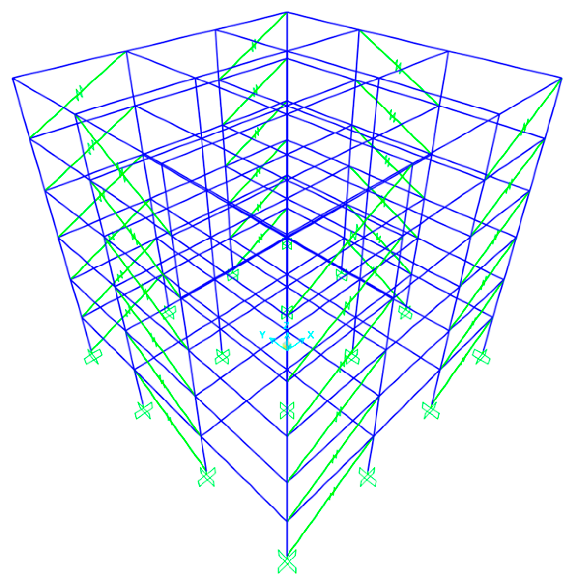
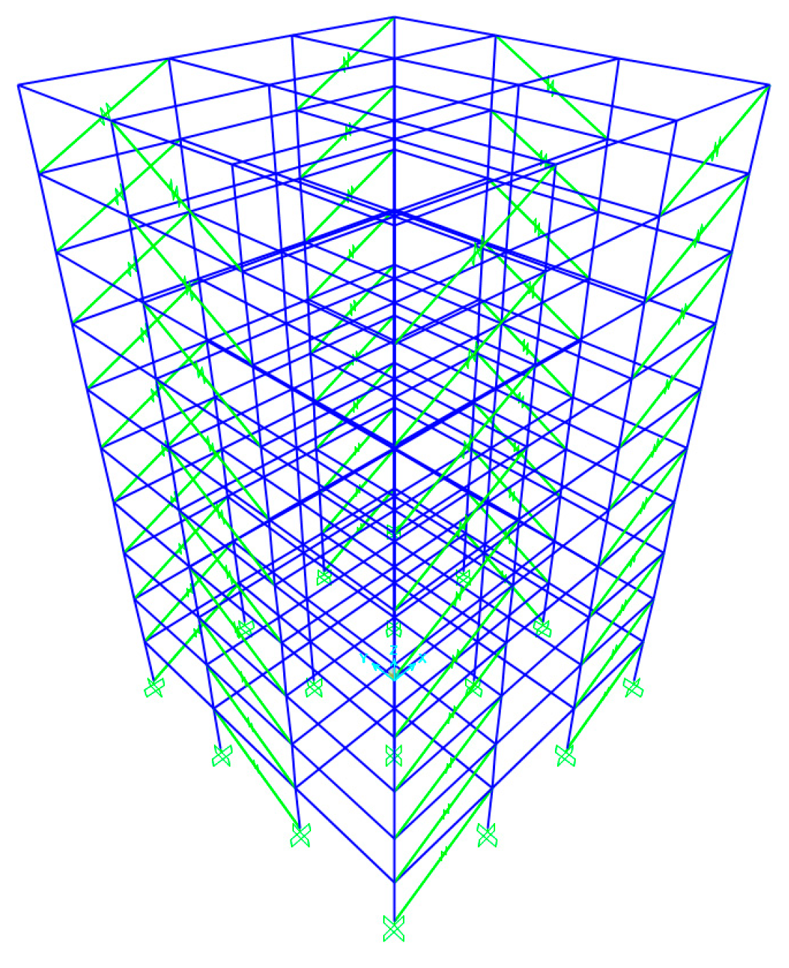
2. Description of the Structures

This study examined two different three-dimensional fixed-base steel buildings: a 6-story building (Figure 1) and a 10-story building (Figure 2). The buildings were characterized by uniform floor heights of 3.0 m and bay widths of 6.0 m. The design included four moment-resisting frames in both the X and Y horizontal directions, with each frame consisting of three bays, resulting in a robust and well-balanced structural configuration.
To size the viscous dampers in terms of their damping coefficient C, it was assumed that the distribution of viscous dampers was uniform along the height. The coefficient C does not have a specified limitation; however, to achieve the desired damping ratio ξ l i n . d of a structure with a linear viscous damper, the following equation may be utilized [1,3,29]:
ξ l i d , m = ξ m + T m j C j c o s 2 θ j ( φ j φ j 1 ) 2 4 π i m i φ i 2
where ξ m is the innate viscous damping of the structure (usually considered to be 0.03), θj is the installation angle of the damper j with respect to the horizontal direction, φjφj–1 is the relative modal displacement of the floors j and j – 1 in the m eigenmode, mi is the mass of the floor i, φi is the modal displacement of the floor i in the m eigenmode, and Tm is the period of the m eigenmode. The equation presented above is only applicable to linear dampers and has to be modified in order to account for nonlinear viscous dampers [1,3,29]. Therefore, assuming the damping ratio ξ n o n l i n . d provided by nonlinear dampers, their damping coefficient can be calculated using Equation (2), which is indicatively expressed below for the dominant mode (m = 1):
ξ n o n l i n . d , 1 = T 1 2 a λ j C j c o s 1 + a θ j ( φ j φ j 1 ) 1 + a ( 2 π ) 3 a A 1 a i m i φ i 2
The rest of the quantities shown in Equation (2) are as follows:   a is the velocity exponent of the nonlinear viscous damper (obviously, a < 1.0 ), A is the first mode displacement of the top floor normalized by unity, and λ is a parameter calculated as follows:
λ = 2 2 + a Γ 2 ( 1 + α / 2 ) Γ 2 + α
where Γ is the gamma function [1,3,29]. Thus, using either Equation (1) for linear viscous dampers or Equation (2) for nonlinear viscous dampers (with a = 0.5 ), one selects the desired damping ratio of the structure (herein, it was considered that ξ l i n . d = ξ n o n l i n . d = 0.30 ) and solves for the damping coefficient C, which essentially represents the total number of viscous dampers placed at each story and along a specific horizontal direction.
The dead load and live load considered were 5.0 kN/m2 and 2.0 kN/m2, respectively, taking into account the presence of a composite slab with a thickness of 14 cm at each floor level. The grade of the steel material used for all beams and columns was S275, whereas the values of the modulus of elasticity and Poisson’s ratio were 210 GPa and 0.3, respectively. The seismic design of the two steel structures considered herein adhered to the stipulations outlined in Eurocode 3 [30], thereby guaranteeing life safety and the no-collapse performance level against the seismic forces delineated by the design spectrum of Eurocode 8 [31]. The design spectrum assumed was the one derived for a peak ground acceleration (PGA) equal to 0.16 g, soil class B, importance factor γ equal to 1.0, and a behavior factor q equal to 4.0. The final sections of beams and columns of the 6- and 10-story buildings are provided in Table 1 and Table 2, respectively.
The fundamental periods along the two horizontal directions X and Y of the 6-story building were 1.44 s and 1.10 s, respectively, whereas the corresponding ones for the 10-story building were 1.95 s and 1.59 s, respectively. Therefore, employing Equation (1), regarding the damping coefficient C of the linear viscous dampers in the 6-story building, one derives C = 6100 kNs/m in the X direction and C = 5700 kNs/m in the Y direction. Assuming further that to place the viscous dampers, two bays were available in the X direction, and in order to reduce their size, it was decided to use two dampers of 3050 kNs/m in the X direction and one of 5700 kNs/m in the Y direction. Similar considerations were made for the 10-story building. Thus, application of Equation (1) led to C = 11,200 kNs/m in the X direction and C = 11,000 kNs/m in the Y direction, and finally, two dampers of 5600 kNs/m were used in the X direction and one of 11,000 kNs/m in the Y direction. For nonlinear viscous dampers, application of Equation (2) and similar consideration regarding their position and size along the X direction led to C = 221 kNs/m in the X direction and C = 205 kNs/m in the Y direction for the 6-story building and C = 375 kNs/m in the X direction and C = 323 kNs/m in the Y direction for the 10-story building. The position of the viscous dampers, exclusively along the MRFs of the perimeter for both buildings, is shown in Figure 1 and Figure 2.

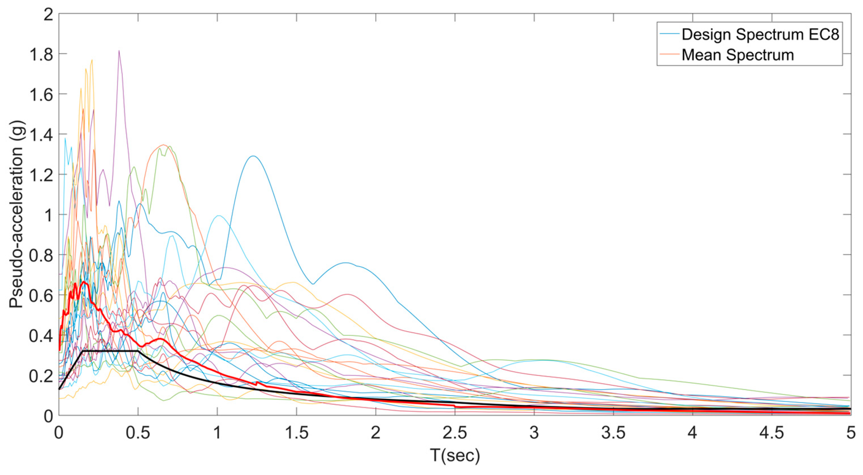
3. Modeling Assumptions and Seismic Motions

The execution of nonlinear time history analyses was performed in SAP 2000 [32]. The examination of the inelastic behavior of structures necessitates an analysis of the potential formation of plastic hinges at the ends of each structural member. This phenomenon can be effectively modeled using a bilinear hysteresis framework. The representation of these plastic hinges is in accordance with the protocols set forth in ASCE 41-13 [33], which delineates generalized force–deformation relationships to depict their operational characteristics. Generally, these relationships consist of an elastic phase, a plastic phase marked by strain hardening, and a phase characterized by strength deterioration. Furthermore, the standard stipulates acceptance criteria for various performance levels, such as immediate occupancy, life safety, and collapse prevention, contingent upon the specifications for plastic rotation.
All floors were regarded as rigid in plan, which serves to enhance the diaphragm action of the floor slabs. In conjunction with material nonlinearities, the geometrical ones were also taken into account by activating the large displacement option of SAP 2000 [32]. The viscous dampers were modeled as discrete damping elements utilizing the link element of SAP 2000 [32]. To create a Rayleigh damping matrix of the structure, the initial stiffness and mass matrices were employed considering a damping ratio of 3.0% for the first two modes of the structure.
In SAP 2000 [32], based on the analytical and experimental findings of [34], linear and nonlinear viscous dampers can be represented through link elements utilizing the “Damper—Exponential” property type. The damping force, denoted as F, is determined using the equation F = C u ˙ a · s g n u ˙ , where C represents the damping coefficient, u ˙ signifies the velocity,   s g n is the signum function, and α indicates the velocity exponent (equal to 0.5 for the nonlinear dampers studied herein).
The seismic response of the 6-story and 10-story structures shown in Figure 1 and Figure 2 was evaluated based on the two horizontal components of the eleven seismic motions (accelerograms) presented in Table 3. For the purposes of the time history analyses performed herein, the seismic motions did not undergo any amplitude scaling or spectral matching processes. According to [24], if at least eleven seismic motions are used, one may use the mean seismic response results obtained from nonlinear time history analyses. The eleven seismic motions were selected so that their 5%-damped response spectrum closely matched the target design spectrum employed herein in the 0.2∙TS1–1.5∙T1 period range, where T1 is the largest predominant period of the two steel buildings and TS1 is the smallest first mode period of the two steel buildings for the two principal horizontal directions of response. Therefore, the period range for the spectral matching purposes was 0.25–2.85 s. The mean response pseudo-acceleration spectrum of the seismic motions of Table 3 along with their individual response spectra and the design spectrum of Eurocode 8 [31] considered for the design of the structures are shown in Figure 3. The damping ratio of all the spectra shown in Figure 3 was 5.0%.
No matter whether linear or nonlinear viscous dampers were employed, the damping coefficients (C) were assumed separately to be equal to 80%, 100% and 120% of the values mentioned in Section 2, i.e., 0.8∙C, 1.0∙C, 1.2∙C, indicating a variable damping capacity as mandated in [23,24]. This way, one sought for the largest response (base shear, displacement, etc.) anticipated. The response results presented that follow are the mean values obtained from nonlinear time history analyses.

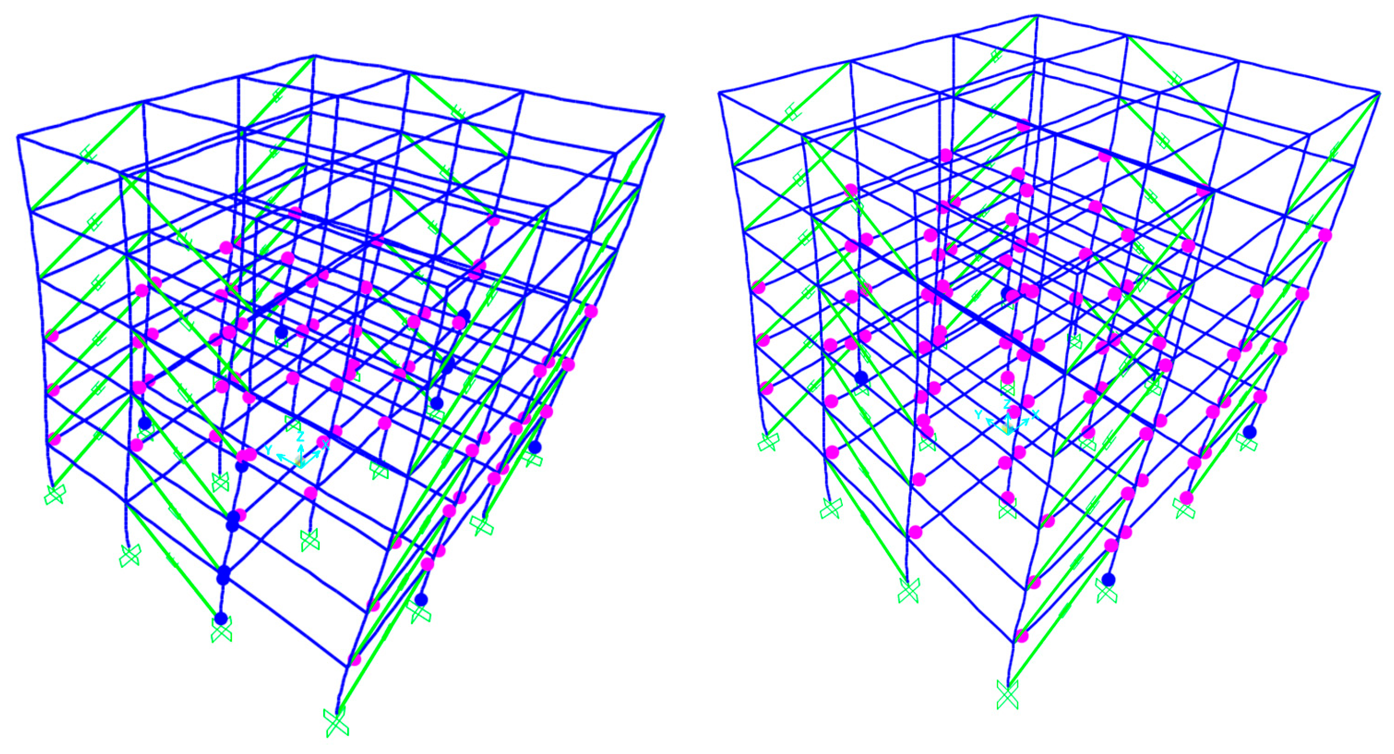
4. Seismic Response Results

4.1. Six-Story Structure

The examination of plastic hinge formation within the 6-story structure equipped with linear viscous dampers indicated significant differences between the damping coefficients of 1.0∙C and 0.8∙C (refer to Figure 4). In particular, with the 0.8∙C damping configuration, there was a marked reduction in the development of plastic hinges throughout the structure, particularly evident in the lower stories, which typically experience the most substantial seismic forces. The distribution of plastic hinges appeared more uniform, reflecting effective energy dissipation throughout the structure. Conversely, the scenario with 1.0∙C led to an increased number of plastic hinges, implying that the lower damping coefficient resulted in increased demands on the structural members. This finding underscores the critical nature of selecting an appropriate damping coefficient to achieve optimal structural performance.
A significant difference could be observed between the undamped structure and the one equipped with 1.2∙C linear dampers in terms of their responses (refer to Figure 5). The undamped structure exhibited a large number of plastic hinges, especially in the lower levels, raising concerns about the potential for a soft-story mechanism, which constitutes an undesirable failure mode. The accumulation of plastic hinges in the lower portions suggested insufficient energy dissipation throughout the structure. In contrast, the structure fitted with linear viscous dampers exhibiting 1.2∙C demonstrated a notable reduction in plastic hinge formation, with the majority of structural elements displaying elastic behavior.
The implementation of nonlinear dampers with varying capacities revealed notable trends in the formation of plastic hinges (refer to Figure 6). Therefore, the configuration with 0.8∙C, 1.0∙C or 1.2∙C demonstrated exceptional performance, characterized by minimal plastic hinge development, and they exhibited the same structural performance.
The inter-story drift ratio (IDR) plots provide essential insights into the deformation behavior of the structure when subjected to seismic forces (Figure 7). The implementation of both linear and nonlinear dampers proved to be highly effective in mitigating drift demands across all levels of the structure. Notably, the 1.2∙C damping configuration achieved the most significant reductions in the IDR, especially in the lower stories where seismic forces are most intense. Even though the 0.8∙C damping configuration was less effective than the higher damping ratios, it still offered considerable improvements over the undamped (no damper) condition, indicating that even moderate damping can yield beneficial results.
The findings related to the residual inter-story drift ratio (RIDR) (Figure 8) offer critical insights into the condition of the structure following an earthquake and its potential for enduring additional deformation resulting from aftershocks. Both linear and nonlinear dampers demonstrated significant efficacy in mitigating the RIDR, with increased damping coefficients generally resulting in enhanced RIDR performance.
The analysis of the absolute acceleration plots offered valuable insights into the dynamic response of the structure and the role of dampers in reducing floor accelerations (Figure 9). The data indicate a more significant reduction in accelerations at the upper stories, highlighting the effectiveness of dampers in controlling higher mode responses. This is particularly important as floor accelerations directly impact nonstructural components and building contents, which can lead to considerable earthquake-related losses [35].
The evaluation of the (structural) base shear responses across both principal directions indicated notable reductions with the application of dampers, which provides vital insights into the overall mitigation of seismic forces (Figure 10 and Figure 11). Linear dampers tended to perform slightly better in terms of the (structural) base shear reduction compared to their nonlinear counterparts at similar damping coefficients. Additionally, the results suggest that increasing the damping coefficient generally enhances (structural) base shear reductions, although this correlation is not strictly linear. It should be noted that structural base shear is defined using only the stiffness property of a structure [36].
Taking into account that a structure with viscous dampers, especially in the presence of nonlinear viscous dampers, may exhibit a larger base shear (as a result of the inclusion of damping forces), one opts for the computation of the inertial base shear [36] in order to be compared with the structural base shear. Thus, Figure 12 and Figure 13 display the inertial base shear values for all the cases of damping coefficients considered.
Upon comparison of the base shear values for the X direction presented in Figure 10 and Figure 12, one finds that (i) for the nonlinear viscous dampers, the structural base shear values lay between 4560 and 5290 kN, while the inertial base shear values were considerably higher, ranging from 4050 to 5210 kN; (ii) for the linear viscous dampers, the structural base shear values lay between 4605 and 4630 kN, while the inertial base shear values were considerably higher, ranging from 3370 to 3500 kN; (iii) for the undamped conditions, the base shear was 3470 kN, compared to an inertial base shear of about 3835 kN. Similarly, upon comparison of the base shear values for the X direction presented in Figure 11 and Figure 13, one finds that (i) for the nonlinear viscous dampers, the structural base shear values lay between 4652 and 4660 kN, while the inertial base shear values were considerably higher, ranging from 3310 to 4300 kN; (ii) for the linear viscous dampers, the structural base shear value was 1865 kN in all the cases, while the inertial base shear values were considerably higher, ranging from 2030 to 2170 kN; (iii) for the undamped conditions, the base shear was 3190 kN, compared to an inertial base shear of about 3150 kN. As a result of analyzing Figure 12 and Figure 13, the computation of both structural and inertial base shear was necessary regardless of whether the viscous dampers were linear or nonlinear.
A thorough investigation into the maximum link forces highlighted the critical elements concerning damper performance and the essential design specifications (Figure 14). It was observed that the nonlinear dampers consistently yielded higher peak forces than the linear dampers under similar damping coefficient scenarios, which carries important consequences for connection design and the overall structural costs. The differences noted in the maximum forces between the two types of dampers indicate that linear dampers might present advantages in terms of less rigorous connection design criteria, although they may require more complex modeling and analysis methods.

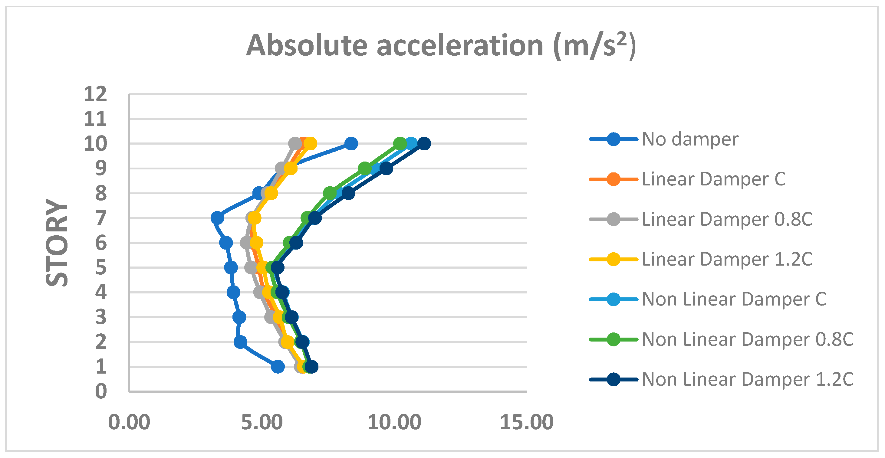
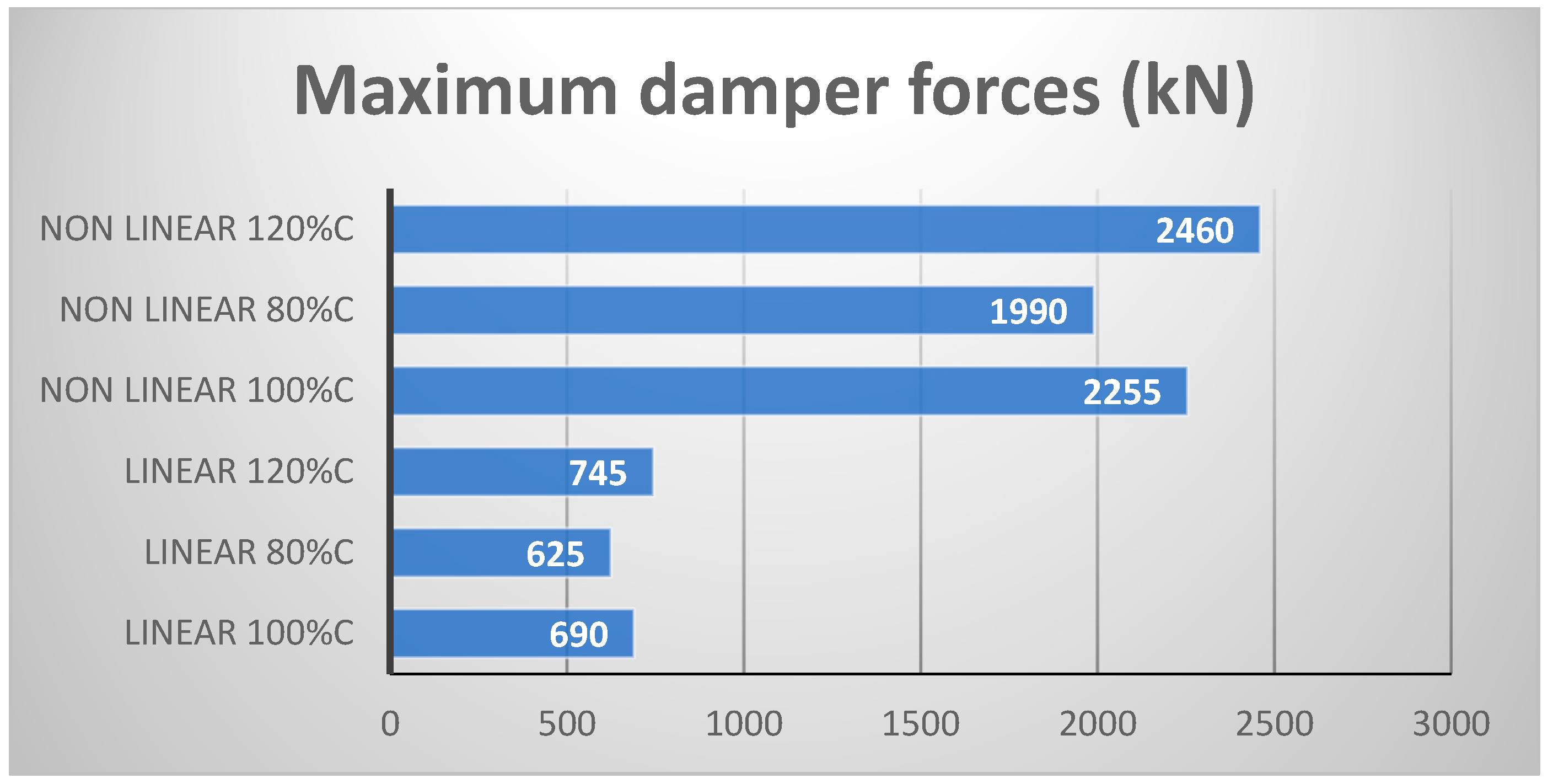
4.2. Ten-Story Structure

The cases of linear dampers with damping coefficients of 1.0∙C and 0.8∙C illustrated a steady increase in the development of plastic hinges as the damping capacity was reduced (Figure 15). Both configurations exhibited a markedly superior performance compared to the undamped scenario. However, the variations between them provide critical insights into the optimization of damping coefficients. The 1.0∙C case was characterized by a more uniform formation of plastic hinges, leading to improved distribution throughout the structure, while the 0.8∙C case revealed more extensive yielding patterns.
A comparison of the undamped and 1.2∙C linear damped conditions in the 10-story structure highlighted substantial differences in seismic response and the occurrence of plastic hinges (Figure 16). The 1.2∙C linear damped condition showed significant yielding along the height of the structure, with particularly alarming concentrations of plastic hinges in critical zones that could lead to detrimental failure mechanisms. In contrast, the undamped condition predominantly exhibited elastic behavior across most of the structure, resulting in minimal plastic hinge development.
The implementation of nonlinear dampers with varying damping coefficients (1.2∙C, 1.0∙C, and 0.8∙C) demonstrated notable trends in the development of plastic hinges and the overall response of the structure (refer to Figure 17). Similar to the findings with linear dampers, an increase in damping coefficients was associated with a reduction in the number of plastic hinges. However, it is important to note that the distribution of these hinges was significantly more uniform when nonlinear dampers were employed. The examination of the transition from 0.8∙C to 1.2∙C underscored the impact of varying damping capacities on the formation patterns of plastic hinges, offering critical insights for the selection of dampers in high-rise construction.
The use of dampers in the 10-story structure yielded considerable reductions in the (structural) base shear responses across both main directions (Figure 18 and Figure 19). This level of effectiveness was significantly higher than what was observed in the 6-storey structure, which can be explained by the greater flexibility and longer fundamental period associated with the taller building. Figure 19 and Figure 20 display the inertial base shear values for all the cases of damping coefficients considered.
Upon comparison of the base shear values for the X direction presented in Figure 18 and Figure 20, one finds that (i) for the nonlinear viscous dampers, the structural base shear values lay between 9325 and 9630 kN, while the inertial base shear values were lower, ranging from 8580 to 8885 kN; (ii) for the linear viscous dampers, the structural base shear values lay between 6390 and 7095 kN, while the inertial base shear values ranged from 5975 to 6700 kN; (iii) for the undamped conditions, the base shear was 4155 kN, compared to a lower inertial base shear of 3520 kN. Similarly, upon comparison of the base shear values for the Y direction presented in Figure 19 and Figure 21, one finds that (i) for the nonlinear viscous dampers, the structural base shear values lay between 3290 and 3365 kN, while the inertial base shear values ranged from 3402 to 3551 kN; (ii) for the linear viscous dampers, the structural base shear values lay between 3010 and 3060 kN, while the inertial base shear values ranged from 3000 to 3071 kN; (iii) for the undamped conditions, the base shear was 2930 kN, compared to an inertial base shear of about 2800 kN. As a result of analyzing Figure 18, Figure 19, Figure 20 and Figure 21, the computation of both structural and inertial base shear was necessary regardless of whether the viscous dampers were linear or nonlinear.
The analysis of the IDR (%) and RIDR (%) for the 10-story structure reveals important insights regarding the effectiveness of linear and nonlinear dampers in controlling story drifts (Figure 22 and Figure 23). The drift profiles indicate that the use of dampers promoted a more consistent distribution of story drifts throughout the building’s vertical extent, which may help to prevent excessive deformation demands in particular stories. Additionally, the results show that both damper types were capable of reducing the maximum drift demands, although their performance was contingent upon the height of the structure and the damping coefficient.
The findings on absolute acceleration for the 10-story building underscore the significant impact of dampers on effectively lowering floor accelerations, with particularly notable effects observed in the upper stories (Figure 24). As noted above, this reduction in acceleration demands is crucial for the protection of nonstructural elements and sensitive building contents, which often constitute a substantial part of the building’s overall value [35].
The analysis of the maximum damper forces in the 10-story structure revealed that these forces were markedly greater than those in the 6-story model, underscoring the increased energy dissipation demands typical of taller buildings (Figure 24 and Figure 25). This information is essential for practical design considerations, particularly regarding the design of connections and the appropriate sizing of dampers. The distribution of forces indicates substantial differences between linear and nonlinear dampers, implying that the type of dampers selected can have a considerable impact on the design criteria for both the supporting structure and its connections.

5. Conclusions

The analysis of the seismic response of the two steel buildings equipped with either linear or nonlinear viscous dampers produced several significant findings that have important implications for the seismic design of similar buildings. These findings certify the results of previous studies in the field, e.g., [25], and are as follows:
  • In general, the incorporation of both linear and nonlinear viscous dampers significantly improved the seismic performance of the buildings without viscous dampers.
  • The effectiveness of viscous dampers was contingent upon the height of the building, with the taller building (10-story) benefiting more than the shorter one (6-story).
  • A higher damping coefficient (1.2∙C) consistently resulted in enhanced performance across all the assessed parameters.
  • Even with lower damping coefficients (0.8∙C), there were notable improvements compared to the scenarios without damping.
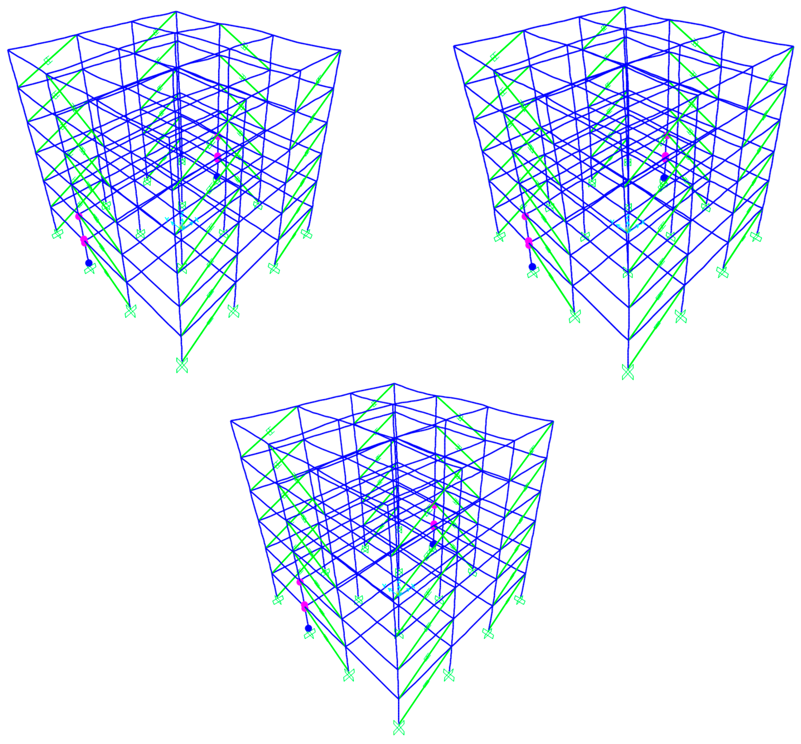
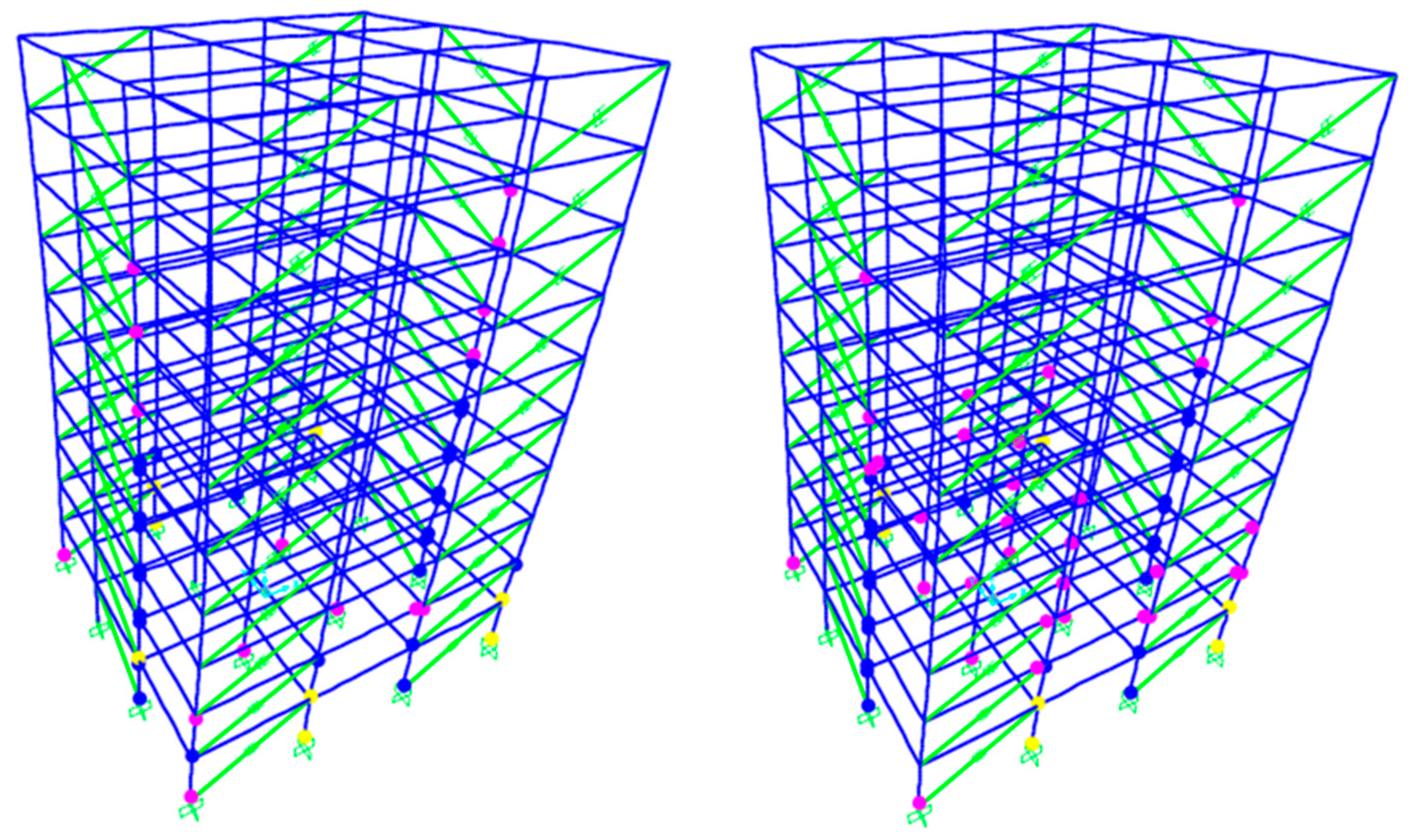
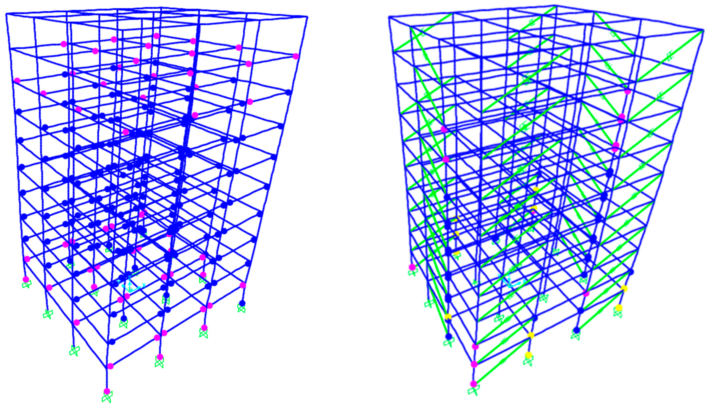
  • Linear dampers contributed to a more uniform distribution of plastic hinges throughout the building.
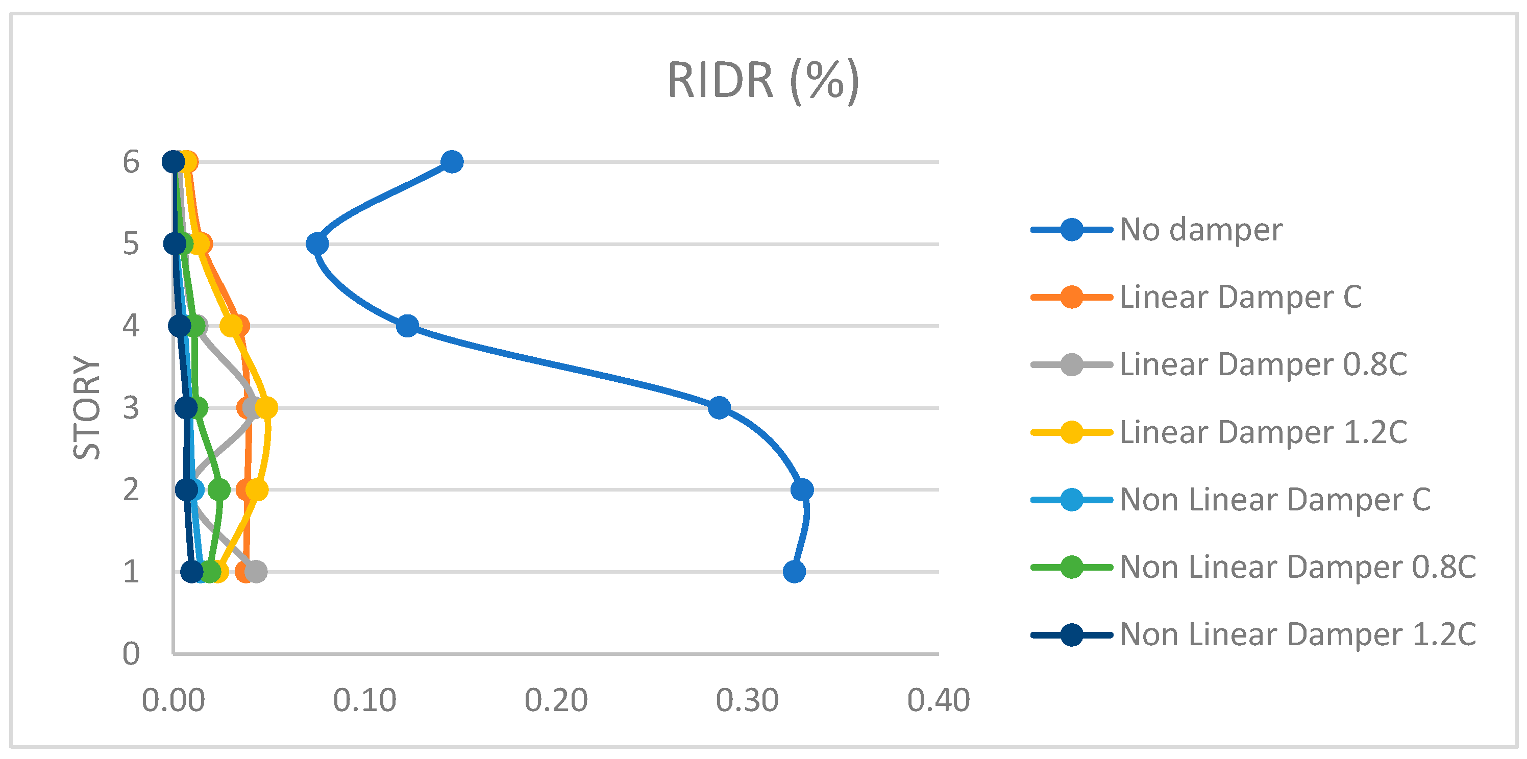
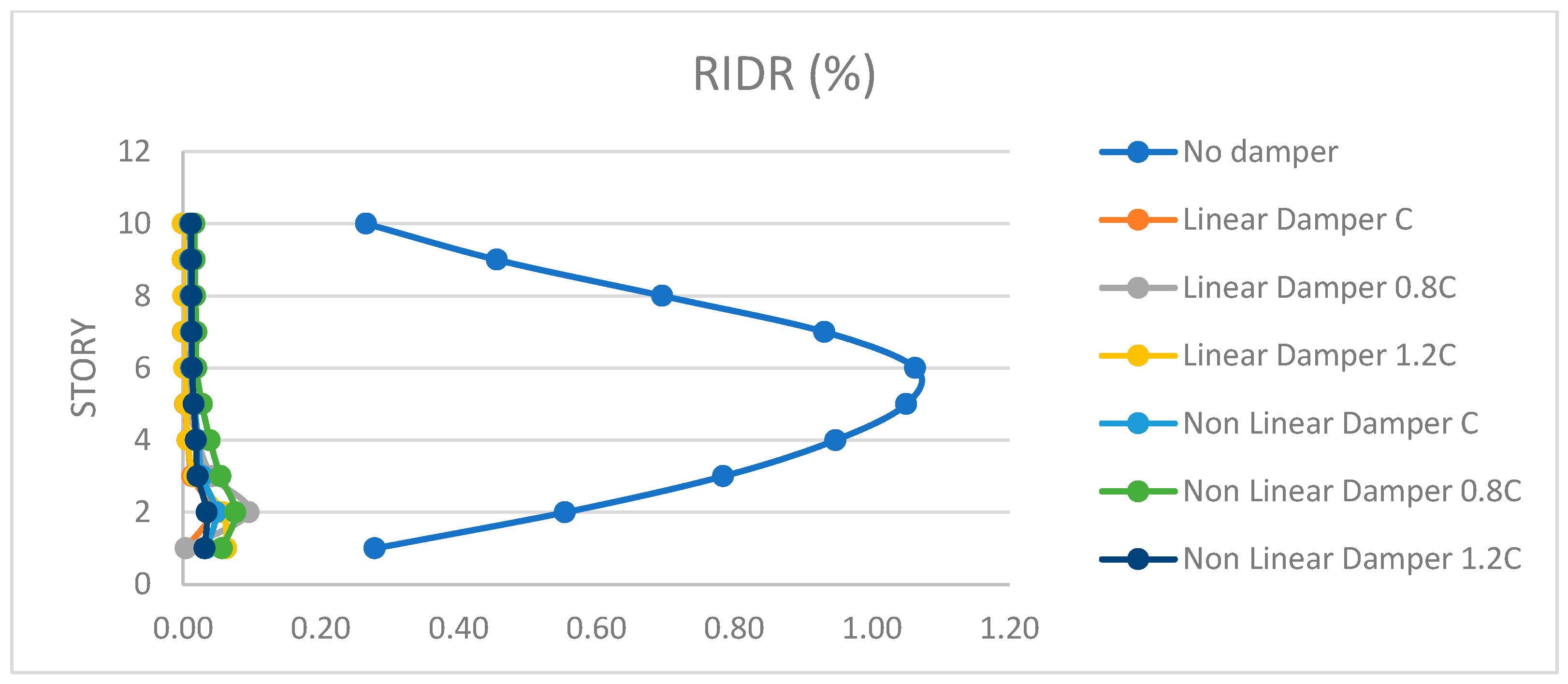
  • The use of both types of dampers led to a significant reduction in both the inter-story drift ratio (IDR) and the relative inter-story drift ratio (RIDR).
  • Higher damping coefficients (1.2∙C) were particularly effective in controlling drift.
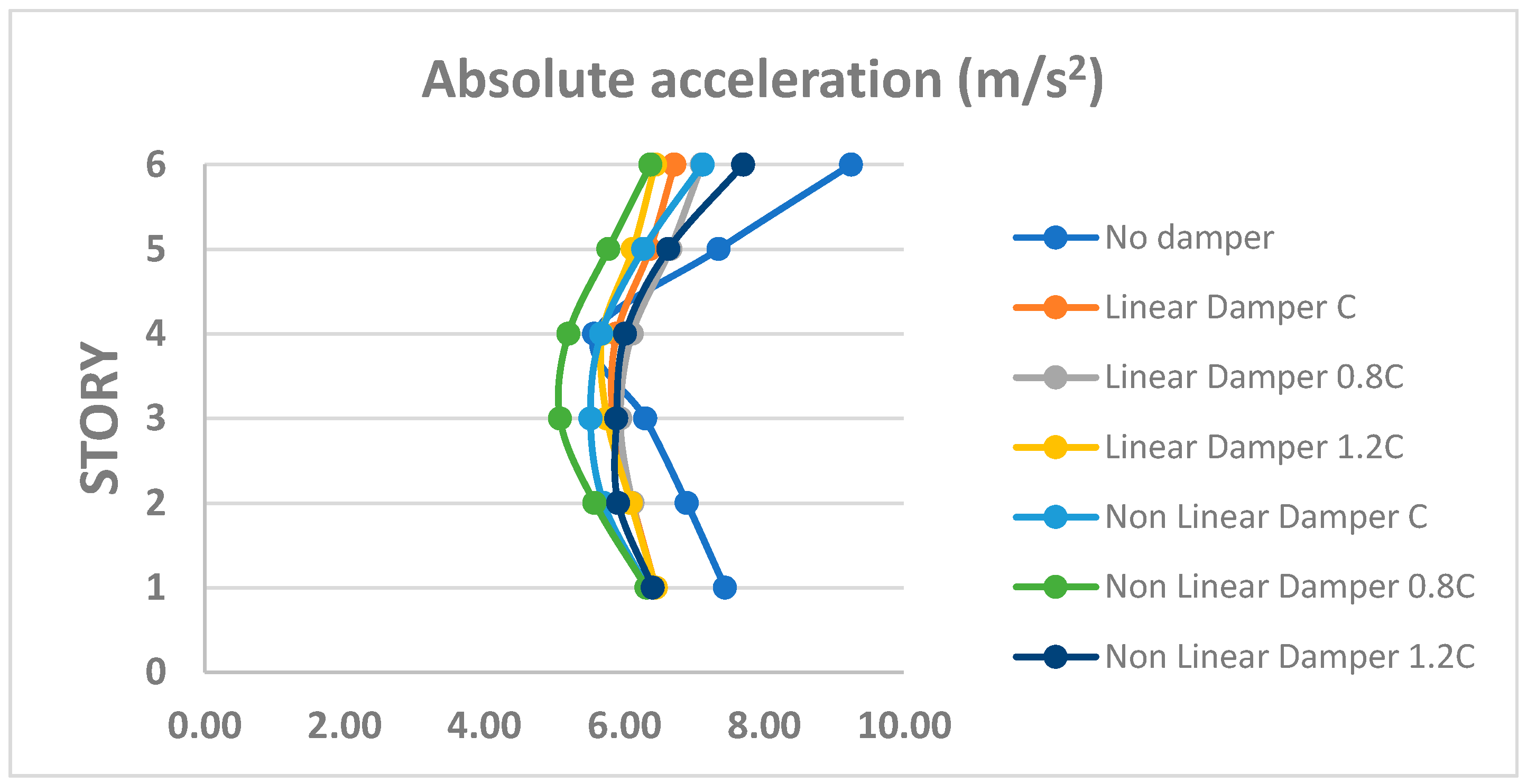
  • Floor accelerations were markedly reduced, especially in the upper levels of the structures.
  • Both linear and nonlinear dampers proved effective in decreasing acceleration demands.
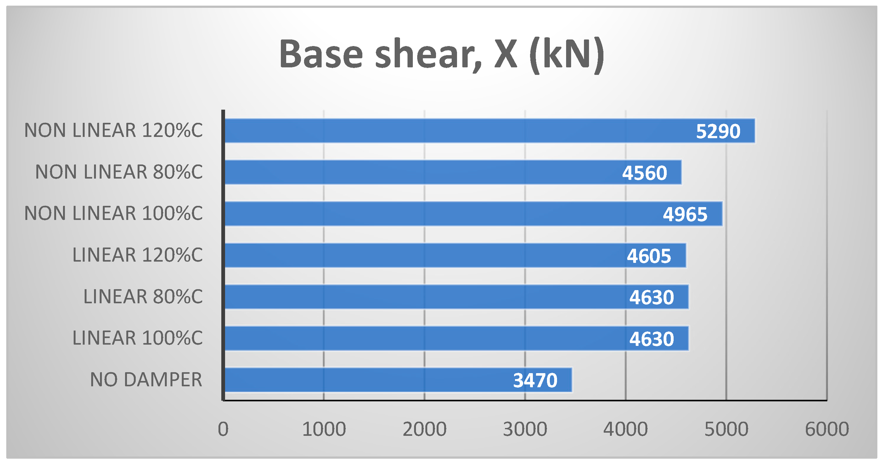
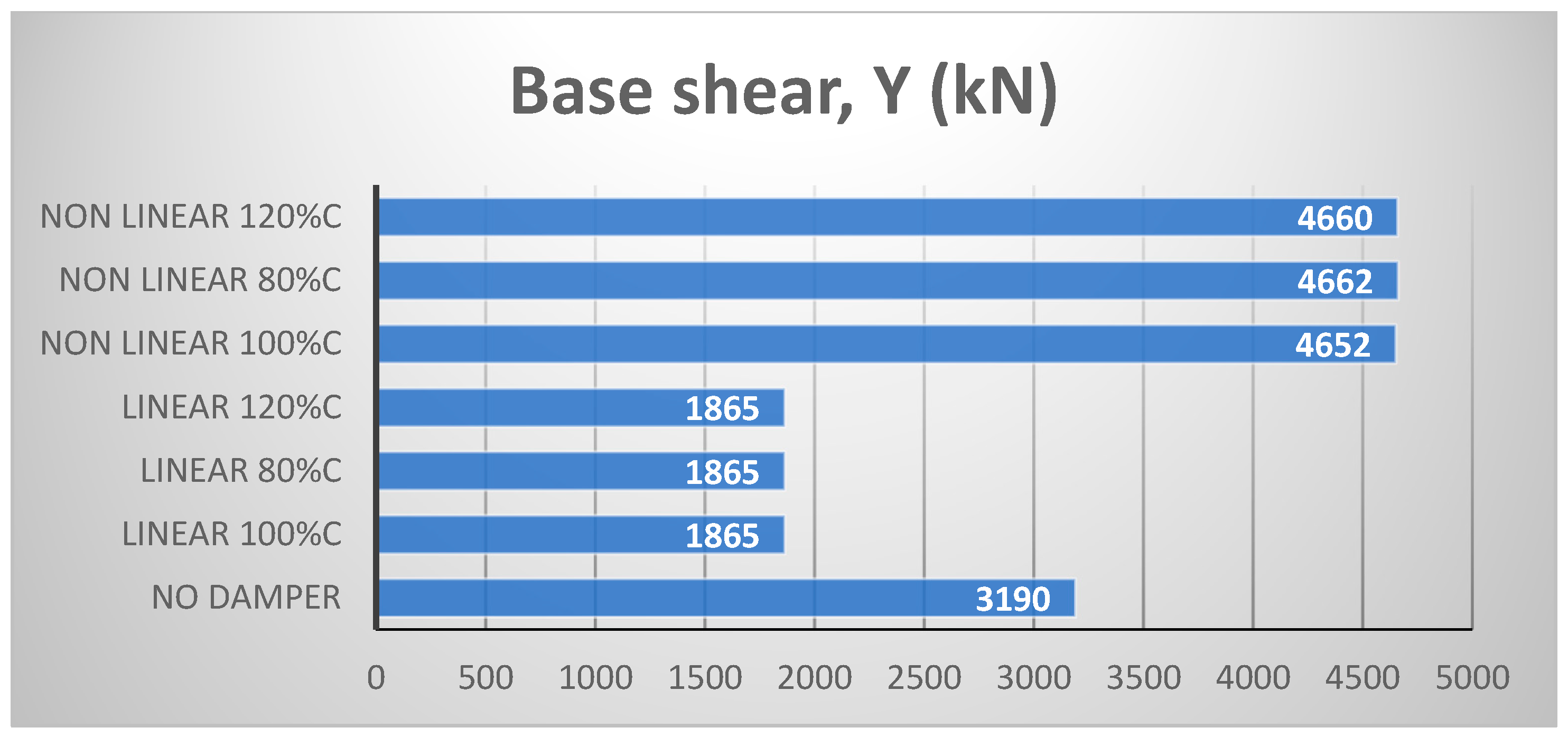
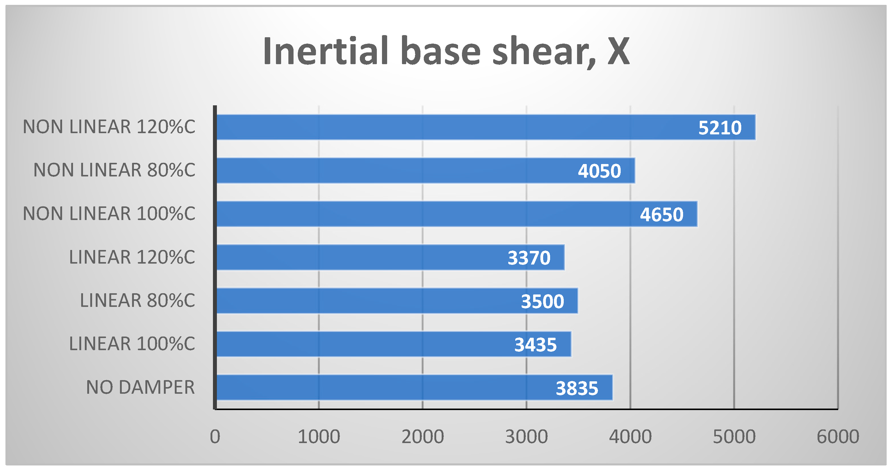
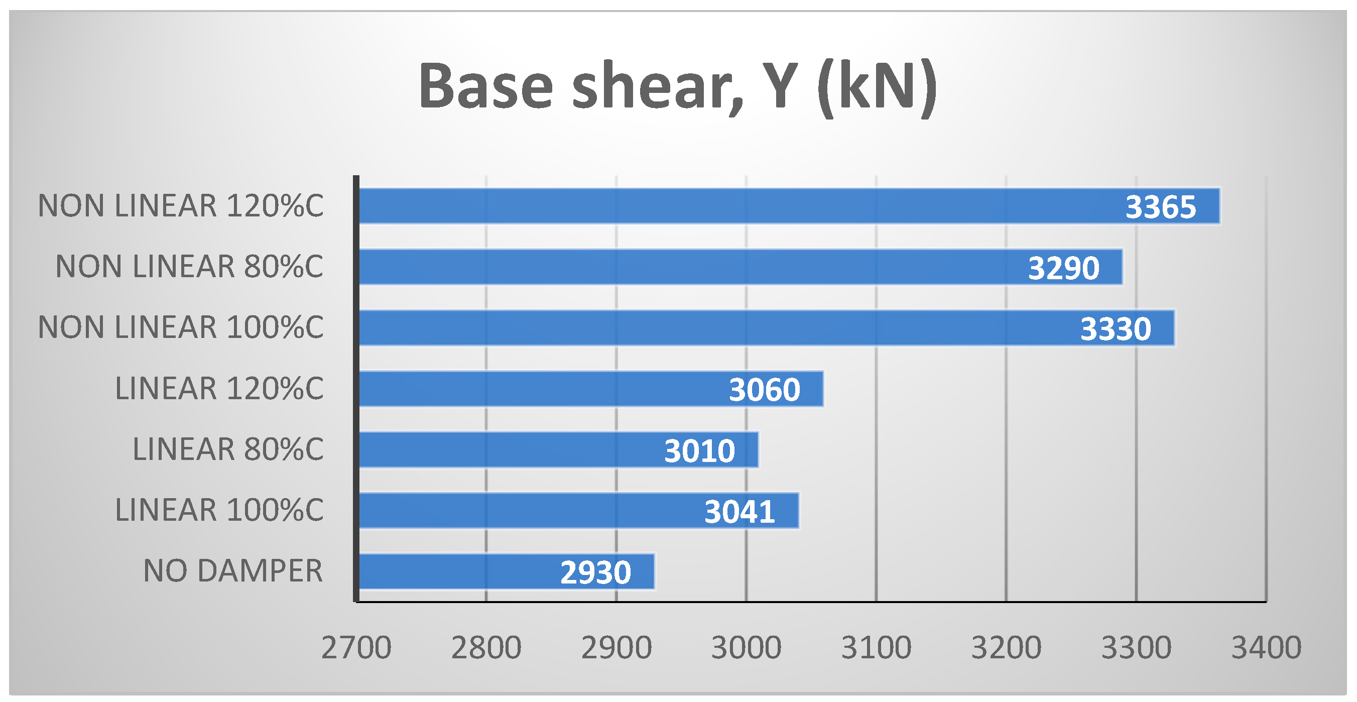
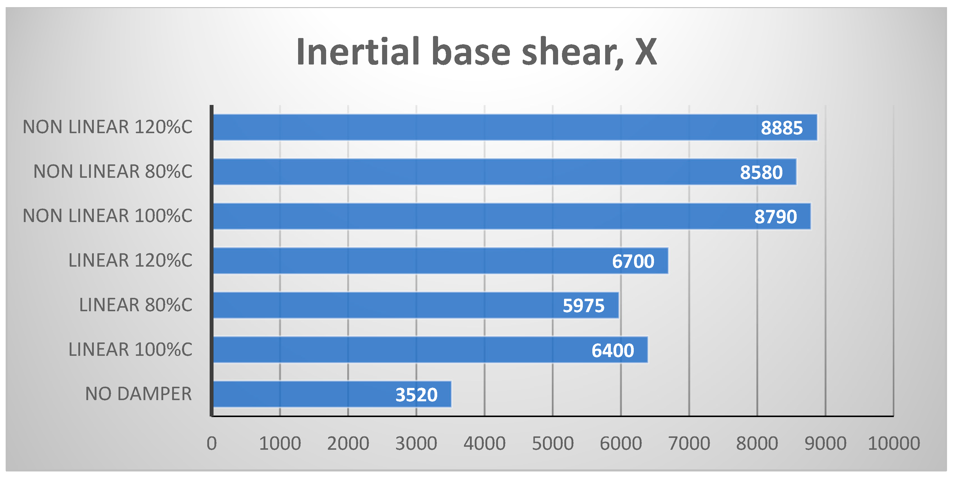
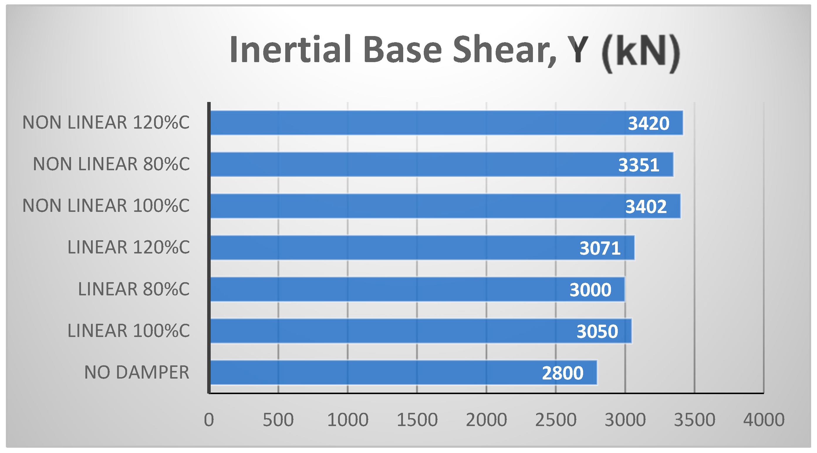
  • Both types of dampers led to increased values of the structural base shear.
  • The computation of both structural and inertial base shear was necessary regardless of whether the viscous dampers were linear or nonlinear.

6. Limitations, Future Research, and Physical Interpretation

Even though this study took into account the variation of the mechanical properties of viscous dampers (through a variable damping coefficient), it did not address the economic implications and installation challenges associated with different damper configurations, which are critical considerations in practical applications. The focus was also limited to viscous dampers, thereby excluding other passive control systems that might offer complementary benefits.
This research opens up several promising pathways for future inquiry. More specifically, studies could investigate the interaction between viscous dampers and other passive control systems, such as tuned mass dampers or base isolation, to formulate hybrid solutions. Moreover, future studies might extend to assessing the performance of three-dimensional steel buildings equipped with viscous dampers under near-fault earthquakes with specific velocity pulse characteristics or by including effects of soil–structure interaction.
The results of the study can be interpreted in a physical context by examining the mechanisms of energy dissipation and the structural response. In the presence of seismic forces, viscous dampers convert kinetic energy into heat through the displacement of fluid, which significantly diminishes the motion of the building. Observations regarding the formation of plastic hinges, inter-story drift patterns, and floor accelerations offer critical insights into how dampers redistribute seismic forces throughout the structure, thus preventing the concentration of damage in specific areas.
An in-depth study of linear and nonlinear viscous dampers can significantly contribute to the enhancement of seismic design codes in the future. Such an analysis can generate empirical evidence that aids in formulating more detailed guidelines for the appropriate selection and installation of dampers within steel structures. Additionally, it has the potential to establish more sophisticated performance-based design standards that take into account the behavior of dampers under varying levels of seismic activity.

Author Contributions

Conceptualization, G.P.; methodology, G.P.; software, P.M.; validation, P.K.; formal analysis, P.K.; investigation, G.P.; data curation, P.K.; writing—original draft preparation, P.K.; writing—review and editing, G.P.; visualization, G.P.; supervision, G.P. All authors have read and agreed to the published version of the manuscript.

Funding

This research received no external funding.

Data Availability Statement

Data will be available upon request.

Conflicts of Interest

The authors declare no conflicts of interest.

References

  1. Christopoulos, C.; Filiatrault, A. Principles of Passive Supplemental Damping and Seismic Isolation; IUSS Press: Pavia, Italy, 2006. [Google Scholar]
  2. Cheng, F.Y.; Jiang, H.; Lou, K. Smart Structures: Innovative Systems for Seismic Response Control; CRC Press: Boca Raton, FL, USA, 2008. [Google Scholar]
  3. Symans, M.D.; Charney, F.A.; Whittaker, A.S.; Constantinou, M.C.; Kircher, C.A.; Johnson, M.W.; McNamara, R.J. Energy dissipation systems for seismic applications: Current practice and recent developments. J. Struct. Eng. ASCE 2008, 134, 3–21. [Google Scholar] [CrossRef]
  4. Connor, J.; Laflamme, L. Structural Motion Engineering; Springer: Cham, Switzerland, 2014. [Google Scholar]
  5. Mahjoubi, S.; Maleki, S. Seismic performance evaluation and design of steel structures equipped with dual-pipe dampers. J. Constr. Steel Res. 2016, 122, 25–39. [Google Scholar] [CrossRef]
  6. Hsu, H.L.; Halim, H. Improving seismic performance of framed structures with steel curved dampers. Eng. Struct. 2017, 130, 99–111. [Google Scholar] [CrossRef]
  7. Katsimpini, P.S.; Papagiannopoulos, G.A.; Askouni, P.K.; Karabalis, D.L. Seismic response of low-rise 3-D steel structures equipped with the seesaw system. Soil Dyn. Earthq. Eng. 2020, 128, 105877. [Google Scholar] [CrossRef]
  8. Javidan, M.M.; Kim, J. A rotational friction damper-brace for seismic design of resilient framed structures. J. Build. Eng. 2022, 51, 104248. [Google Scholar] [CrossRef]
  9. Mao, H.; Yan, X.; Wei, X.; Liu, X. Seismic analysis of a frame structure equipped with displacement-amplified torsional dampers. Structures 2022, 41, 190–202. [Google Scholar] [CrossRef]
  10. Ellsa Sarassantika, I.P.; Hsu, H.L. Upgrading framed structure seismic performance using steel lever-armed dampers in braces. Eng. Struct. 2023, 280, 115683. [Google Scholar] [CrossRef]
  11. Available online: https://www.taylordevices.com/projects/ (accessed on 29 December 2024).
  12. Constantinou, M.C.; Tadjbakhsh, I.G. Optimum design of a first story damping system. Comput. Struct. 1983, 17, 305–310. [Google Scholar] [CrossRef]
  13. Uetani, K.; Tsuji, M.; Takewaki, I. Application of an optimum design method to practical building frames with viscous dampers and hysteretic dampers. Eng. Struct. 2003, 25, 579–592. [Google Scholar] [CrossRef]
  14. Takewaki, I. Optimal damper placement for minimum transfer functions. Earthq. Eng. Struct. Dynam. 1997, 26, 1113–1124. [Google Scholar] [CrossRef]
  15. Akehashi, H.; Takewaki, I. Frequency-domain optimal viscous damper placement using lower-bound transfer function and multimodal adaptability. Struct. Control Health Monit. 2022, 29, e2951. [Google Scholar] [CrossRef]
  16. Lopez-Garcia, D. A simple method for the design of optimal damper configurations in MDOF structures. Earthq. Spectra 2001, 17, 387–398. [Google Scholar] [CrossRef]
  17. Lavan, O. Optimal design of viscous dampers and their supporting members for the seismic retrofitting of 3D irregular frame structures. J. Struct. Eng. 2015, 141, 04015026. [Google Scholar] [CrossRef]
  18. De Domenico, D.; Ricciardi, G.; Takewaki, I. Design strategies of viscous dampers for seismic protection of building structures: A review. Soil Dyn. Earthq. Eng. 2019, 118, 144–165. [Google Scholar] [CrossRef]
  19. Kookalani, S.; Shen, D.; Zhu, L.L.; Lindsey, M. An overview of optimal damper placement methods in structures. Iran. J. Sci. Technol. Trans. Civ. Eng. 2022, 46, 1–20. [Google Scholar] [CrossRef]
  20. Del Gobbo, G.M.; Williams, M.S.; Blakeborough, A. Comparing fluid viscous damper placement methods considering total-building seismic performance. Earthq. Eng. Struct. Dyn. 2018, 47, 2864–2886. [Google Scholar] [CrossRef]
  21. CEN/TC 340—EN 15129; Anti-Seismic Devices. European Committee for Standardization (CEN): Brussels, Belgium, 2018.
  22. Wang, S.; Mahin, S.A. Seismic retrofit of a high-rise steel moment-resisting frame using fluid viscous dampers. Struct. Des. Tall Spec. Build. 2017, 26, e1367. [Google Scholar] [CrossRef]
  23. ASCE/SEI 7-16; Minimum Design Loads and Associated Criteria for Buildings and Other Structures. American Society of Civil Engineers: Reston, VA, USA, 2017.
  24. ASCE/SEI 7-22; Minimum Design Loads and Associated Criteria for Buildings and Other Structures. American Society of Civil Engineers: Reston, VA, USA, 2022.
  25. Kitayama, S.; Constantinou, M.C. Seismic Performance of Buildings with Viscous Damping Systems Designed by the Procedures of ASCE/SEI 7-16. J. Struct. Eng. 2018, 144, 4018050. [Google Scholar] [CrossRef]
  26. Hatzigeorgiou, G.D.; Pnevmatikos, N.G. Maximum damping forces for structures with viscous dampers under near-source earthquakes. Eng. Struct. 2014, 68, 1–13. [Google Scholar] [CrossRef]
  27. Logotheti, V.E.; Kafetzi, T.C.; Papagiannopoulos, G.A.; Karabalis, D.L. On the use of interstorey velocity for the seismic retrofit of steel frames with viscous dampers. Soil Dyn. Earthq. Eng. 2020, 129, 105312. [Google Scholar] [CrossRef]
  28. Banazadeh, M.; Ghanbari, A. Seismic performance assessment of steel moment-resisting frames equipped with linear and nonlinear fluid viscous dampers with the same damping ratio. J. Constr. Steel Res. 2017, 136, 215–228. [Google Scholar] [CrossRef]
  29. Hwang, J.S.; Huang, Y.N.; Yi, S.L.; Ho, S.Y. Design formulations for supplemental viscous dampers to building structures. J. Struct. Eng. ASCE 2008, 134, 22–31. [Google Scholar] [CrossRef]
  30. EN 1993-1; Eurocode 3. Design of Steel Structures—Part 1.1: General Rules and Rules for Buildings. Committee for Standardization (CEN): Brussels, Belgium, 2009.
  31. Eurocode 8. Design of Structures for Earthquake Resistance, Part 1–1: General Rules, Seismic Actions and Rules for Buildings; European Committee for Standardization (CEN): Brussels, Belgium, 2005. [Google Scholar]
  32. SAP 2000. Static and Dynamic Finite Element Analysis of Structures: Version 25.0; Computers and Structures: Berkeley, CA, USA, 2022. [Google Scholar]
  33. ASCE 41-13. Seismic Evaluation and Retrofit of Existing Buildings; American Society of Civil Engineers: Reston, VA, USA, 2017. [Google Scholar]
  34. Seleemah, A.; Constantinou, M.C. Investigation of Seismic Response of Buildings with Linear and Nonlinear Fluid Viscous Dampers; Report No. NCEER 97-0004; National Center for Earthquake Engineering Research, State University of New York: Buffalo, NY, USA, 1997. [Google Scholar]
  35. Rodriguez, M.E.; Restrepo, J.I.; Carr, A.J. Earthquake-induced floor horizontal accelerations in buildings. Earthq. Eng. Struct. Dyn. 2002, 31, 693–718. [Google Scholar] [CrossRef]
  36. Goel, R.K. Comparison of base shears estimated from floor accelerations and column shears. Earthq. Spectra 2011, 27, 939. [Google Scholar] [CrossRef]
Figure 1. Six-story building.
Vibration 08 00011 g001
Figure 2. Ten-story building.
Vibration 08 00011 g002
Figure 3. Mean spectrum, design spectrum, and seismic motions.
Vibration 08 00011 g003
Figure 4. Plastic hinge exhibition at the members of the 6-story structure: linear viscous dampers with 1.0∙C (left) and 0.8∙C (right).
Vibration 08 00011 g004
Figure 5. Plastic hinge exhibition at the members of the 6-story structure: without viscous dampers (left) and with linear viscous dampers with 1.2∙C (right).
Vibration 08 00011 g005
Figure 6. Plastic hinge exhibition at the members of the 6-story structure: nonlinear viscous dampers with 1.2∙C (upper left), 0.8∙C (upper right), and 1.0∙C (lower centered).
Vibration 08 00011 g006
Figure 7. IDR (%) for the cases of linear and nonlinear viscous dampers and their variable damping capacity (6-story structure).
Vibration 08 00011 g007
Figure 8. RIDR (%) for the cases of linear and nonlinear viscous dampers and their variable damping capacity (6-story structure).
Vibration 08 00011 g008
Figure 9. Absolute acceleration (m/s2) for the cases of linear and nonlinear viscous dampers and their variable damping capacity (6-story structure).
Vibration 08 00011 g009
Figure 10. Base shear (in kN) along the X direction for the cases of linear and nonlinear viscous dampers and their variable damping capacity (6-story structure).
Vibration 08 00011 g010
Figure 11. Base shear (in kN) along the Y direction for the cases of linear and nonlinear viscous dampers and their variable damping capacity (6-story structure).
Vibration 08 00011 g011
Figure 12. Inertial base shear (in kN) along the X direction for the cases of linear and nonlinear viscous dampers and their variable damping capacity (6-story structure).
Vibration 08 00011 g012
Figure 13. Inertial base shear (in kN) along the Y direction for the cases of linear and nonlinear viscous dampers and their variable damping capacity (6-story structure).
Vibration 08 00011 g013
Figure 14. Maximum damper forces for the cases of linear and nonlinear viscous dampers and their variable damping capacity (6-story structure).
Vibration 08 00011 g014
Figure 15. Plastic hinge exhibition at the members of the 10-story structure: linear viscous dampers with 1.0∙C (left) and with 0.8∙C (right).
Vibration 08 00011 g015
Figure 16. Plastic hinge exhibition at the members of the 10-story structure: without viscous dampers (left) and with linear viscous dampers with 1.2∙C (right).
Vibration 08 00011 g016
Figure 17. Plastic hinge exhibition at the members of the 10-story structure: nonlinear viscous dampers with 1.2∙C (upper left), 0.8∙C (upper right), and 1.0∙C (lower centered).
Vibration 08 00011 g017
Figure 18. Base shear (in kN) along the X direction for the cases of linear and nonlinear viscous dampers and their variable damping capacity (10-story structure).
Vibration 08 00011 g018
Figure 19. Base shear (in kN) along the Y direction for the cases of linear and nonlinear viscous dampers and their variable damping capacity (10-story structure).
Vibration 08 00011 g019
Figure 20. Inertial base shear (in kN) along the X direction for the cases of linear and nonlinear viscous dampers and their variable damping capacity (10-story structure).
Vibration 08 00011 g020
Figure 21. Inertial base shear (in kN) along the Y direction for the cases of linear and nonlinear viscous dampers and their variable damping capacity (10-story structure).
Vibration 08 00011 g021
Figure 22. IDR (%) for the cases of linear and nonlinear viscous dampers and their variable damping capacity (10-story structure).
Vibration 08 00011 g022
Figure 23. RIDR (%) for the cases of linear and nonlinear viscous dampers and their variable damping capacity (10-story structure).
Vibration 08 00011 g023
Figure 24. Absolute acceleration (m/s2) for the cases of linear and nonlinear viscous dampers and their variable damping capacity (10-story structure).
Vibration 08 00011 g024
Figure 25. Maximum damper forces for the cases of linear and nonlinear viscous dampers and their variable damping capacity (10-story structure).
Vibration 08 00011 g025
Table 1. Sections of beams and columns for the 6-story building.
StoryColumnBeam
1stHEB400IPE300
2ndHEB400IPE300
3ndHEB400IPE300
4ndHEB400IPE300
5ndHEB400IPE300
6ndHEB400IPE300
Table 2. Sections of beams and columns for the 10-story building.
StoryColumnBeam
1stHEB450IPE360
2ndHEB450IPE360
3rdHEB450IPE360
4thHEB450IPE360
5thHEB450IPE360
6thHEB450IPE360
7thHEB400IPE300
8thHEB400IPE300
9thHEB400IPE300
10thHEB400IPE300
Table 3. Seismic motions.
No.EarthquakeDateStationMw
1Bam, Iran26 December 2003Bam6.5
2Cape Mendocino, U.S.A.25 April 1992Cape Mendocino6.9
3Darfield, New Zealand3 September 2010Greendale7.0
4Superstition Hills, U.S.A.24 November 1987Parachute Test Site6.5
5Kobe, Japan17 January 1995Takatori6.9
6Loma Prieta, U.S.A.17 October 1989Los Gatos7.0
7San Fernando, U.S.A.9 February 1971Pacoima Dam6.6
8Cape Mendocino, U.S.A.25 April 1992Petrolia6.9
9Vrancea, Romania30 August 1986INCERC7.3
10El Salvador, El Salvador13 January 2001Observatorio7.6
11El Salvador, El Salvador13 January 2001Observatorio7.6
Disclaimer/Publisher’s Note: The statements, opinions and data contained in all publications are solely those of the individual author(s) and contributor(s) and not of MDPI and/or the editor(s). MDPI and/or the editor(s) disclaim responsibility for any injury to people or property resulting from any ideas, methods, instructions or products referred to in the content.

