


An Overview of the CMS High Granularity Calorimeter †


Abstract
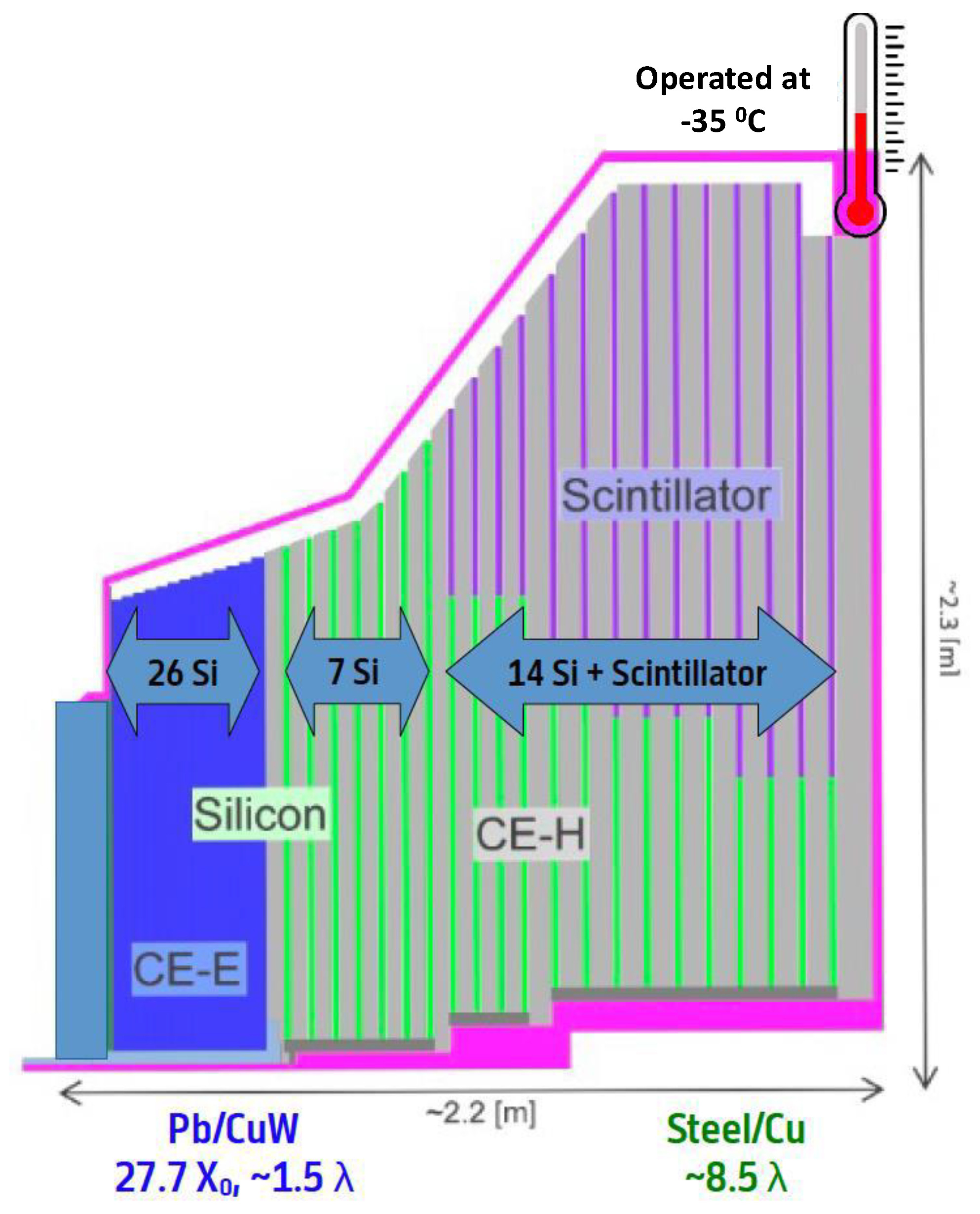
:1. Introduction
2. Active Elements
2.1. Silicon Sensors and Silicon Modules
2.2. Scintillators and Scintillator Tile Modules
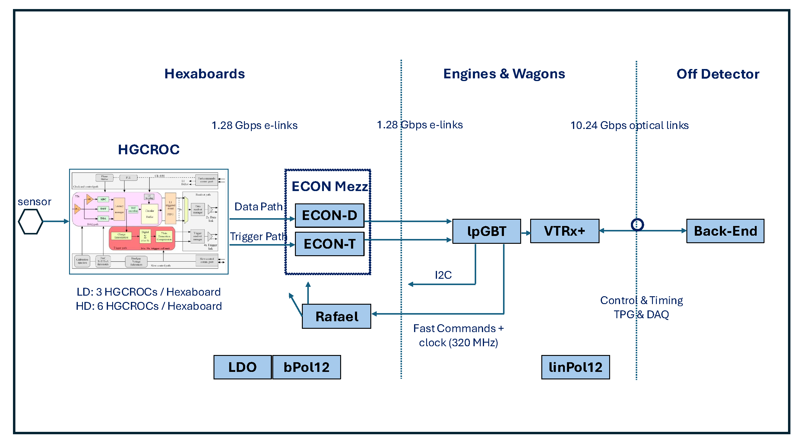
3. Electronics Overview
3.1. Front-End Electronics
3.2. Back-End Electronics
3.3. Control and Safety Systems
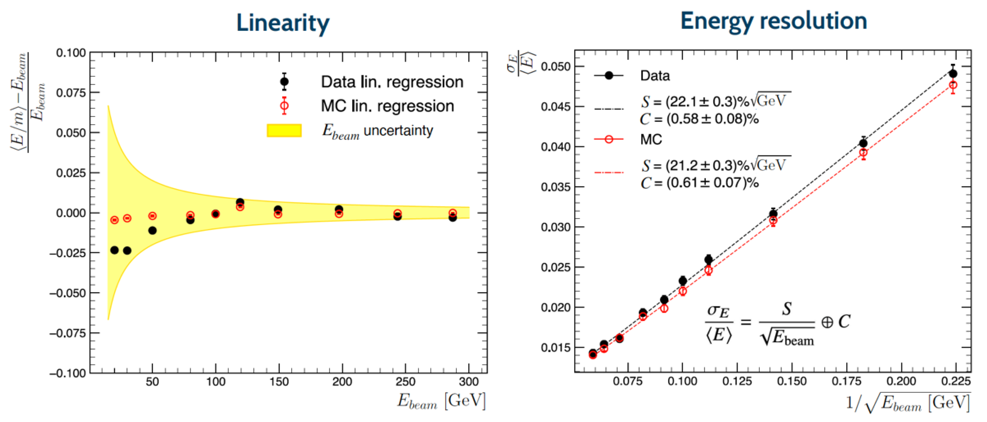
4. The Beam Tests Results and System Validation
5. Conclusions
Funding
Data Availability Statement
Conflicts of Interest
References
- CMS Collaboration. The CMS experiment at the CERN LHC. J. Instrum. 2008, 3, S08004. [Google Scholar] [CrossRef]
- CMS Collaboration. Development of the CMS detector for the CERN LHC Run 3. J. Instrum. 2024, 19, P05064. [Google Scholar] [CrossRef]
- CMS Collaboration. The Phase-2 Upgrade of the CMS Endcap Calorimeter; CERN-LHCC-2017-023; CERN LHC Experiments Committee: Geneva, Switzerland, 2017; Volume 23. [Google Scholar] [CrossRef]
- Almeida, P. Versatile systems for characterization of large-area silicon pad sensors for highly-granular calorimetry. J. Instrum. 2020, 15, C06050. [Google Scholar] [CrossRef]
- Brodolin, E. Silicon sensors for the CMS HGCAL upgrade: Challenges, sensor design and electrical characterization. J. Instrum. 2020, 15, C05068. [Google Scholar] [CrossRef]
- Brondolin, E.; Dannheim, D.; Kulis, S.; Maier, A.A.; Pitters, F.; Quast, T.; Sicking, E. ARRAY: An Open Source, Modular and Probe-Card based System with Integrated Switching Matrix for Characterization of Large Area Silicon Pad Sensors. Nucl. Instrum. Meth. A 2019, 940, 168–173. [Google Scholar] [CrossRef]
- Akchurin, N.; Almeida, P.; Altopp, G.; Alyari, M.; Bergauer, T.; Brondolin, E.; Burkle, B.; Frey, W.D.; Gecse, Z.; Heintz, U.; et al. Charge collection and electrical characterization of neutron irradiated silicon pad detectors for the CMS High Granularity Calorimeter. J. Instrum. 2020, 15, P09031. [Google Scholar] [CrossRef]
- CMS HGCAL Collaboration. Neutron irradiation and electrical characterisation of the first 8” silicon pad sensor prototypes for the CMS calorimeter endcap upgrade. J. Instrum. 2023, 18, P08024. [Google Scholar] [CrossRef]
- Kieseler, J.; de Almeida, P.G.; Kałuzińska, O.A.; Mühlnikel, M.C.; Diehl, L.; Sicking, E.; Zehetner, P. Isothermal annealing of radiation defects in silicon bulk material of diodes from 8” silicon wafers. J. Instrum. 2023, 18, P09010. [Google Scholar] [CrossRef]
- CMS HGCAL Collaboration. Construction and commissioning of CMS CE prototype silicon modules. J. Instrum. 2021, 16, T04002. [Google Scholar] [CrossRef]
- CALICE Collaboration. Construction and Commissioning of the CALICE Analog Hadron Calorimeter Prototype. J. Instrum. 2010, 5, P05004. [Google Scholar]
- CALICE Collaboration. A highly granular SiPM-on-tile calorimeter prototype. JoP Conf. Ser. 2019, 1162, 012012. [Google Scholar] [CrossRef]
- Thienpont, D.; de La Taille, C. Performance study of HGCROC-V2: The front-end electronics for the CMS High Granularity Calorimeter. J. Instrum. 2020, 15, C04055. [Google Scholar] [CrossRef]
- Caratelli, A.; Bonacini, S.; Kloukinas, K.; Marchioro, A.; Moreira, P.; De Oliveira, R.; Paillard, C. The GBT-SCA, a radiation tolerant ASIC for detector control and monitoring applications in HEP experiments. J. Instrum. 2015, 10, C03034. [Google Scholar] [CrossRef]
- Soós, C.; Détraz, S.; Olanterä, L.; Sigaud, C.; Troska, J.; Vasey, F.; Zeiler, M. Versatile Link PLUS transceiver development. J. Instrum. 2017, 12, C03068. [Google Scholar] [CrossRef]
- Available online: https://www.hirose.com/product/series/FX11?lang=en (accessed on 6 January 2025).
- Available online: https://www.molex.com/molex/products/part-detail/pcb_receptacles/5054730810 (accessed on 6 January 2025).
- Luyi, S.; Jinyi, F.; Xiaohua, Y. Forward Error Correction. In Proceedings of the 2012 Fourth International Conference on Computational and Information Sciences, Chongqing, China, 17–19 August 2012; pp. 37–40. [Google Scholar] [CrossRef]
- Available online: https://www.picmg.org/openstandards/advancedtca/ (accessed on 6 January 2025).
- Rose, A.W.; Parker, D.; Iles, G.; Sahin, O.; Bausson, P.A.; Tsirou, A.; Fedi, G.; Verdini, P.G.; Ardilla, L.; Balzer, M.; et al. Serenity: An ATCA prototyping platform for CMS Phase-2. PoS TWEPP2018 2019, 343, 115. [Google Scholar] [CrossRef]
- Hegeman, J.; Blažek, R.; Behrens, U.; Branson, J.; Brummer, P.; Cittolin, S.; Silva-Gomes, D.D.; Darle, G.L.; Deldicque, C.; Dobson, M.; et al. First measurements with the CMS DAQ and Timing Hub prototype-1. PoS TWEPP2019 2020, 370, 111. [Google Scholar] [CrossRef]
- Erickson, K.T. Programmable logic controllers. IEEE Potentials 1996, 15, 14–17. [Google Scholar] [CrossRef]
- Akchurin, N.; Apreysan, A.; Banerjee, S.; Barney, D.; Bilki, B.; Bornheim, A.; Bueghly, J.; Callier, S.; Candelise, V.; Chang, Y.H.; et al. First beam tests of prototype silicon modules for the CMS High GranularityEndcap Calorimeter. J. Instrum. 2018, 13, P10023. [Google Scholar] [CrossRef]
- CMS HGCAL Collaboration. The DAQ system of the 12,000 Channel CMS High Granularity Calorimeter Prototype. J. Instrum. 2021, 16, T04001. [Google Scholar] [CrossRef]
- Belloni, A.; Chen, Y.M.; Dyshkant, A.; Edberg, T.K.; Eno, S.; Freeman, J.; Krohn, M.; Lai, Y.; Lincoln, D.; Los, S.; et al. Test beam study of SiPM-on-tile configurations. J. Instrum. 2021, 16, P07022. [Google Scholar] [CrossRef]
- CMS HGCAL Collaboration. Response of a CMS HGCAL silicon-pad electromagnetic calorimeter prototype to 20–300 GeV positrons. J. Instrum. 2022, 17, P05022. [Google Scholar] [CrossRef]
- CMS HGCAL Collaboration. Performance of the CMS High Granularity Calorimeter prototype to charged pion beams of 20–300 GeV/c. J. Instrum. 2023, 18, P08014. [Google Scholar] [CrossRef]
- CMS HGCAL Collaboration. Timing performance of the CMS High Granularity Calorimeter prototype. J. Instrum. 2024, 19, P04015. [Google Scholar] [CrossRef]
- The CMS Collaboration. Comparison of Test Beam Data with Simulation Using the HGCAL Clustering Algorithms CLUE and CLUE3D. CERN CMS Detector Performance Note, CMS-DP-2023-092, CERN-CMS-DP-2023-092. Available online: https://cds.cern.ch/record/2883615 (accessed on 19 December 2024).
Disclaimer/Publisher’s Note: The statements, opinions and data contained in all publications are solely those of the individual author(s) and contributor(s) and not of MDPI and/or the editor(s). MDPI and/or the editor(s) disclaim responsibility for any injury to people or property resulting from any ideas, methods, instructions or products referred to in the content. |
© 2025 by the author. Licensee MDPI, Basel, Switzerland. This article is an open access article distributed under the terms and conditions of the Creative Commons Attribution (CC BY) license (https://creativecommons.org/licenses/by/4.0/).
Share and Cite
Akgün, B., on behalf of the CMS HGCAL Collaboration. An Overview of the CMS High Granularity Calorimeter. Particles 2025, 8, 4. https://doi.org/10.3390/particles8010004
Akgün B on behalf of the CMS HGCAL Collaboration. An Overview of the CMS High Granularity Calorimeter. Particles. 2025; 8(1):4. https://doi.org/10.3390/particles8010004
Chicago/Turabian StyleAkgün, Bora on behalf of the CMS HGCAL Collaboration. 2025. "An Overview of the CMS High Granularity Calorimeter" Particles 8, no. 1: 4. https://doi.org/10.3390/particles8010004
APA StyleAkgün, B., on behalf of the CMS HGCAL Collaboration. (2025). An Overview of the CMS High Granularity Calorimeter. Particles, 8(1), 4. https://doi.org/10.3390/particles8010004