Abstract
Artificial roughness applied to a Solar Air Heater (SAH) absorber plate is a popular technique for increasing its total thermal efficiency (). In this paper, the influence of geometrical parameters of V-down ribs attached below the corrugated absorbing plate of a SAH on the was examined. The impacts of key roughness parameters, including relative pitch (6–12), relative height (0.019–0.043), angles of attack (30–75°), and Re (1000–20,000), were examined under real weather conditions. The SAH roughened by V-down ribs was predicted using an in-house developed conjugate heat-transfer numerical model. The maximum SAH was shown to be 78.8% as predicted under the steady-state conditions of Re = 20,000, solar irradiance G = 1000 W/m2, p/e = 8, e/D = 0.043, and α = 60. The result was 15.7% greater efficiency compared to the default smooth surface. Under real weather conditions, the of the roughened SAH with single- and double-glass covers were 17.7 and 20.1%, respectively, which were higher than those of the smooth SAH.
1. Introduction
Global environmental degradation and growing energy consumption are concerns that will acquire even more prominence in the near future. It is critical that societies shift to accessible, renewable energy resources and maintain a balance between sustainability and economic benefits [1]. The use of renewable energy sources for daily energy needs is rapidly growing, and solar energy is an essential source that has a variety of uses, including direct/indirect heating and photovoltaic power generation [2,3]. The solar air heater (SAH) collector is essential for solar energy conservation and by heating the surrounding air can be used for a variety of purposes, including heating, cooling, and drying [4]. A SAH is relatively cheap to buy and maintain, but it has a low thermal efficiency because of the low thermo-physical characteristics of the air in the laminar sub-layer region over the heated absorber plate [5]. Artificial roughness of various patterns on the absorber plate can be used to alleviate the sub-layer disadvantage and improve system effectiveness [6,7,8].
In recent years, creating artificial roughness on the SAH absorber plate has been a popular research topic (e.g., [9,10]). A study by Prasad et al. [11] presented an SAH roughened by small diameter wires that showed remarkably enhanced performance. The wire generated turbulence over the heated surface, breaking the laminar sub-layer and increasing the convective heat transfer coefficient. The impacts of W-shaped rib roughened surface on the performance of a SAH in a duct flow were investigated in [12]. The results revealed increases in the Nusselt number (Nu) (up to 2.36 times) and in the friction factor (f) (up to 2.01 times).
Hans et al. [13] facilitated multiple V-shaped ribs to roughen the absorber plate of a SAH, which resulted in a higher convective heat-transfer coefficient. In the latter study, Nu increased by 6 times compared to the smooth SAH, while f increased by 5 times. In addition, Momin et al. [14] used a V-rib with a = 60° and found that Nu increased by a factor of 1.14 compared with that of the inclined-ribbed SAH. Therefore, The V-ribbed SAHs had noticeable benefits over the inclined-ribs ones under the same operational conditions. Jin et al. [15] conducted a numerical study of a SAH roughened by multiple V-ribs and found that the heat transfer improved considerably, and the thermal performance rose by a factor of 2.35. Istanto et al. [16] conducted an investigation into the influence of on the V-down ribs on the heat-transfer coefficient and friction factor across a SAH duct. The latter study showed that, compared to the smooth absorbing plate, the greatest increases of Nu and f were 2.34 and 2.45 times, respectively. Karwa et al. [17] used the gaps in the V-ribs to induce turbulence at several spots along the flow direction across the SAH.
According to the abovementioned literature, the roughened SAH absorbing plate improved system thermal efficiency. As such, there was a significantly deeper pressure drop throughout the system and consequently an increase in power consumption. In our analysis, the impacts of V-down ribs on the SAH were investigated for a wide range of Re. The influence of the V-down rib SAH geometrical parameters, such as p/e, e/D, and , on its thermal efficiency was numerically examined and validated under real weather conditions. Furthermore, the SAH roughened by V-down ribs was predicted using an in-house developed conjugate heat-transfer numerical model. The literature has not given enough attention to this matter; hence, the originality of a work that contributes to this field of study is noticeable. In what follows, the analysis and models are detailed in Section 2. In Section 3, the results and illustrative date are presented. The results are summarised in Section 4.
2. The Model
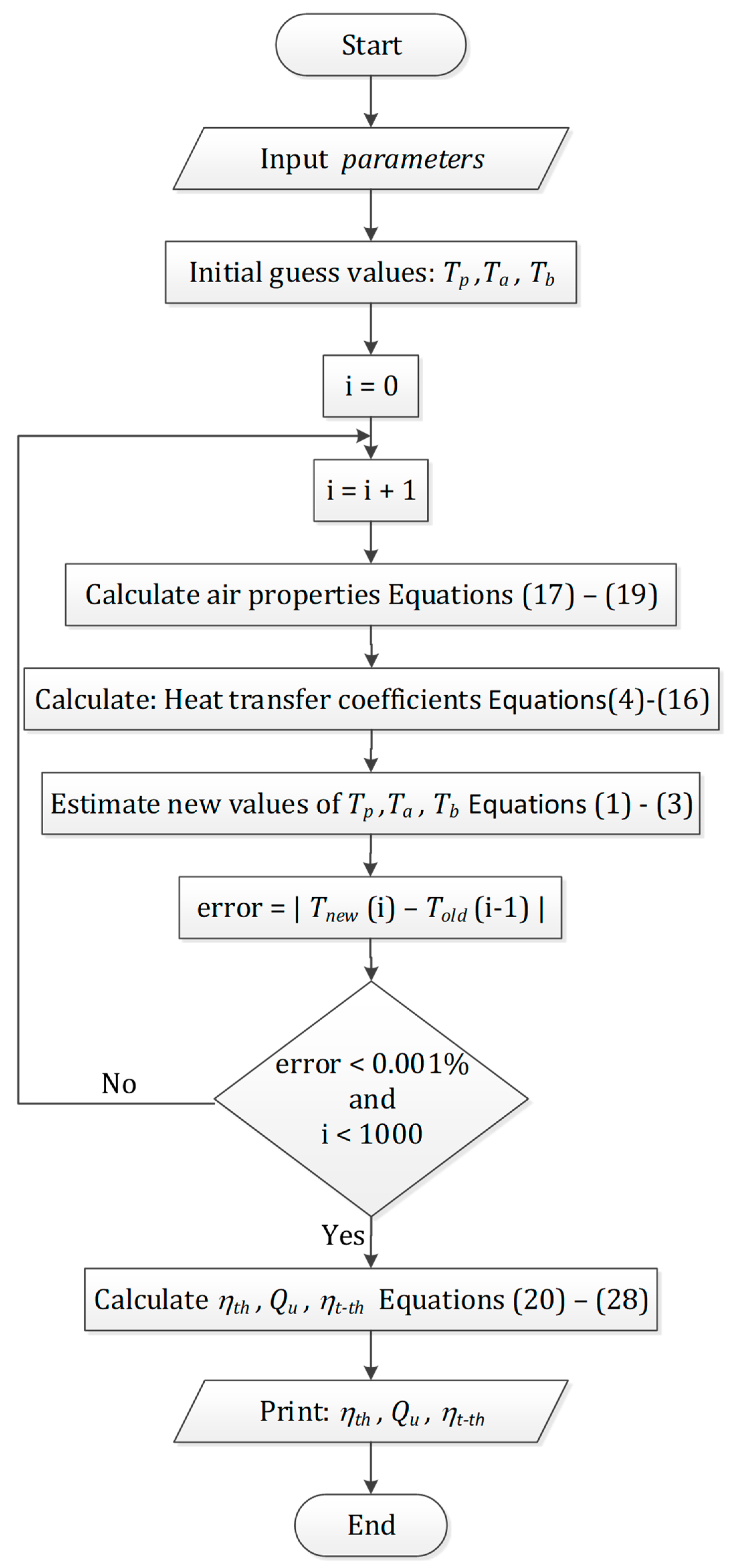
As explained above, SAH with artificial roughness is expected to perform better than a smooth-surface SAH because it leads to an enhanced heat-transfer coefficient. In addition, the roughness elements on the heated surface thinned the absorber plate viscous sub-layer, showing that the thermal efficiency of a corrugated SAH is better than that of a flat plate SAH [18]. In this work, both effects were included: a corrugated absorber plate and V-down ribs on the backside of the heated, as indicated in Figure 1. The SAH with a 60° corrugation angle consisted of a 4 mm glass cover, 1 mm absorbing and bottom plates, and 50 mm back insulation. The air flows through an equilateral triangle channel created by the combination of the absorber and bottom plates. Two SAHs with equal components and dimensions were investigated: one with V-down ribs and one without. To derive the energy-balance equation for each SAH component without distorting the basic physical condition, the following assumptions were used [19]:

Figure 1.
Schematic diagram of (a) SAH components (b) section A-A shows V-down ribs, and (c) a zoomed-in view of V-down ribs.
- The SAH is modelled using a steady-state flow.
- The heat transfer between the components of a SAH is one-dimensional.
- The SAH’s side heat losses are neglected, and there is no air seepage from the collector.
- At sky temperature, thermal radiation occurs between the SAH and its surroundings.
2.1. Energy Analysis
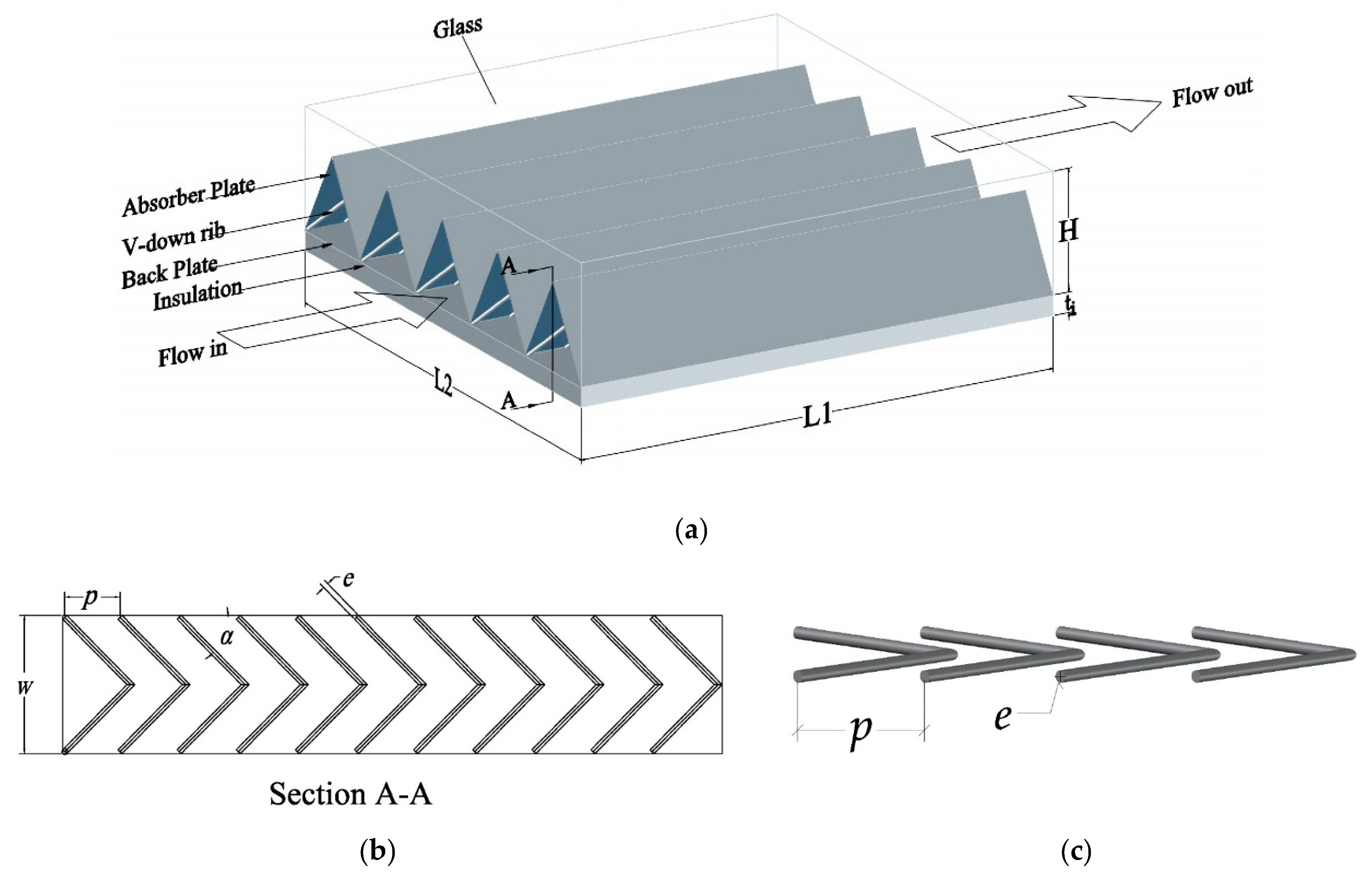
The SAH with a roughened heated surface has the same thermal behaviour as that of a traditional SAH. The absorber plate takes in solar irradiance and transfers heat to the air. Therefore, the same approach used to determine insolation and heat losses for a traditional SAH could be used for a roughened SAH. A schematic diagram of the energy flow between SAH components is depicted in Figure 2. Based on the energy flow diagram, the energy balance equations per unit area for the absorber plate, air, and backplate are expressed as:
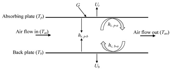
Figure 2.
Energy flow diagram among SAH elements.
A large loss coefficient is related to flat-plate solar collectors. The following correlation (suggested by Malhotra et al. [20]) was used to calculate the top loss coefficient (Ut):
where L is the spacing between the cover and absorber plate; M is the number of glass covers; and and are calculated as:
The convection heat transfer coefficient owing to the wind (hw) is calculated by [19]:
Back-loss coefficient (Ub) is determined by using thermal conductivity (λi) and thickness (ti) of insulation as [19]:
The convective heat transfer coefficient of airflow over the absorber plate is equal to that between air and the backplate as suggested by Hedayatizadeh [21], and calculated as:
where b is the half-height of the flow channel and λa is the thermal conductivity of air.
For a smooth triangular conduit, Nu is proportional to the Reynolds number (Re). As a result, before deciding which Nu equation to use, Re must be determined [22].
where Vin is the inlet air velocity.
Hollands and Shewen [22] recommended the following relation for Nu inside the triangular SAH conduit, which can be stated as:
where n is the number of collectors connected in series, and Nu1 and are functions of Re. For various flow conditions, Hollands and Shewen [22] suggested the following relationships for and :
For a SAH having V-down ribs on the absorbing plate, the Nu was determined from an empirical equation, which was correlated by Hans et al. [13] as follows:
The thermal radiation coefficient between the absorber and backplates can be calculated as [19]
The following empirical correlations were suggested by Gao et al. [23] to determine the density, dynamic viscosity and thermal conductivity of air, respectively:
where Tf is the average air temperature across the SAH in Kelvin, which is computed as . The specific heat at constant pressure of air () is assumed to be equal to 1006 J/kg K.
2.2. Performance Analysis
The thermal efficiency (ηth) of a SAH based on the First Law of Thermodynamics can be defined as the ratio of the useful energy gain (Qu) to the solar irradiance over time [19]:
Total thermal efficiency () is the effect of useful heat gain minus power consumption by the fan that drives air through the SAH channels over time to the solar irradiance over the same period, and it is crucial for determining whether an increase in pressure drop improves thermal efficiency. As a result, indicates the SAH’s actual economic performance, which can be calculated as [24]
It is necessary to consider the energy losses associated with the power consumed by the fan. Following [10,25,26], these losses are assumed to be the fan efficiency = 0.65, the efficiency of the electric motor = 0.88, the efficiency of electrical transmission from the power plant = 0.92 and the thermal conversion efficiency of the power plant . These coefficients can be shortened into the conversion correction factor , which has a value of 0.18. Pm, the mechanical power consumed by the blower to force the air throughout the SAH, can be calculated as [27]:
The pressure drop across the SAH () is determined as [28]
where f is the friction factor calculated using the Hedayatizadeh et al. [21] The relations for a smooth SAH are
where f1 and ϕ are functions of the Re number, which are determined as
For SAH having V-down ribs on the absorbing plate, the following empirical correlation is used to estimate [13]:
To validate the current numerical model in comparison with other experimental data, the root-mean-square error (RMSE) was used here. The degree of concordance between the mathematical (xi) and experimental (yi) findings of the smooth SAH was quantified using statistical analysis. The RMSE was determined as [4]:
2.3. Numerical Algorithm
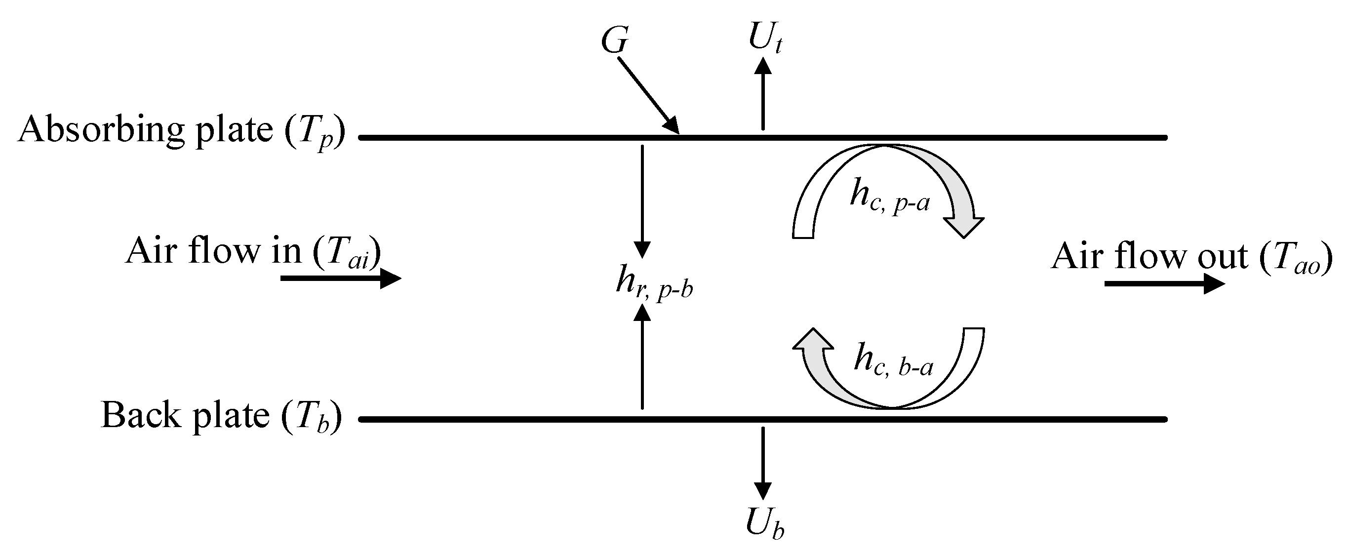
Based on energy flow Equations (1)–(3), there has not been a sufficient analytical solution to the temperatures of the SAH components Tp, Tb, and Ta. Furthermore, the efficiencies and most coefficients of the heat transfer are functions of these temperatures. Therefore, temperatures, efficiencies, and heat-transfer coefficients are determined numerically by iterations (please see Figure A1, Appendix A). All relevant computations are programmed using an in-house developed MATLAB code (version R2019b). The solution technique begins by calculating the heat transfer coefficients based on guessed temperatures, which are subsequently used to predict new temperatures. The run loop is iterative until it reaches an a priori value of 0.001%, which is obtained from the absolute difference between the old and updated temperatures (). The process was continued until the absolute differences were equal or less than 0.001%. The values of fixed and variable input parameters used in the MATLAB code are shown in Table 1.

Table 1.
Parameters used in our numerical solution.
2.4. Validation of the Model
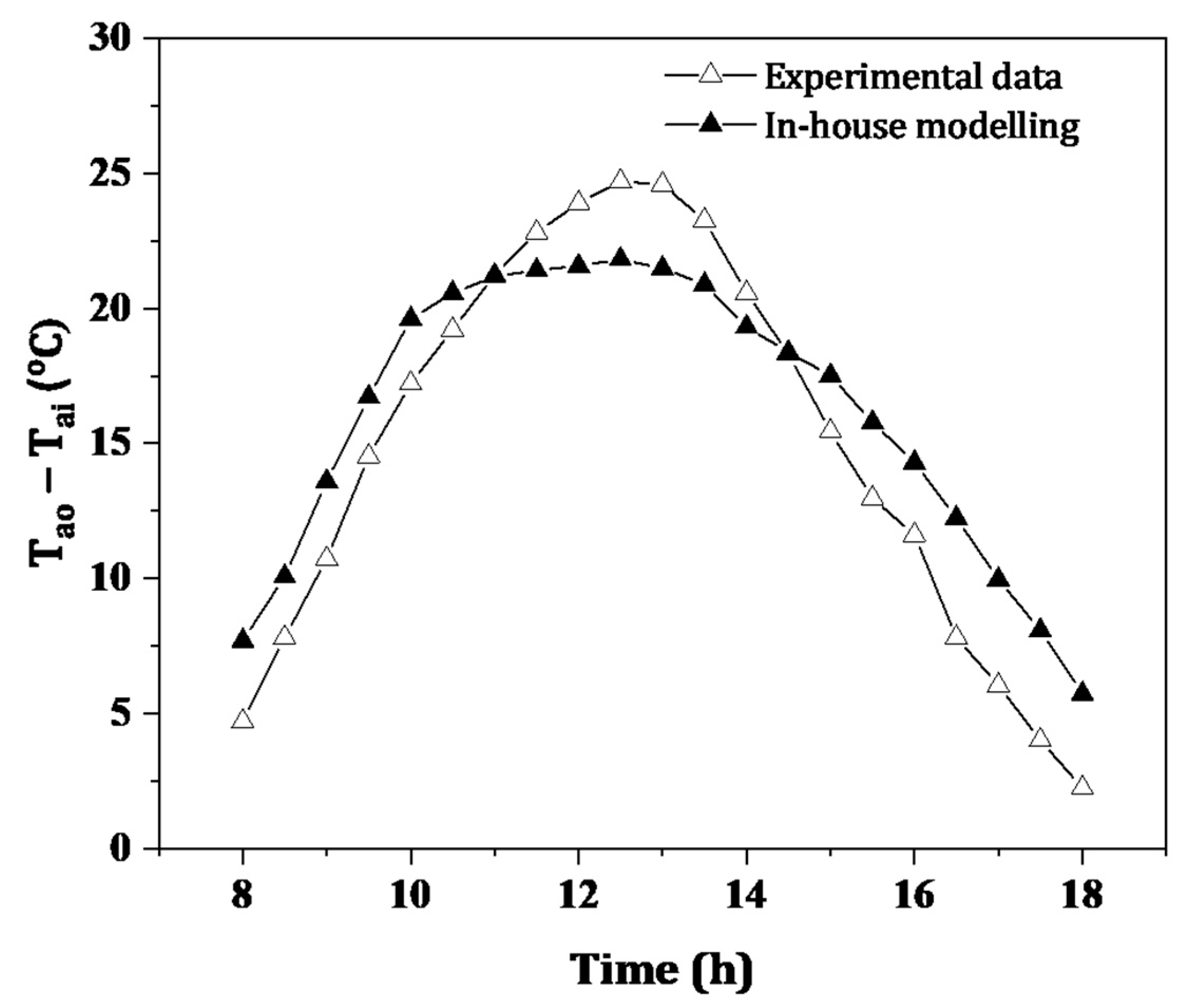
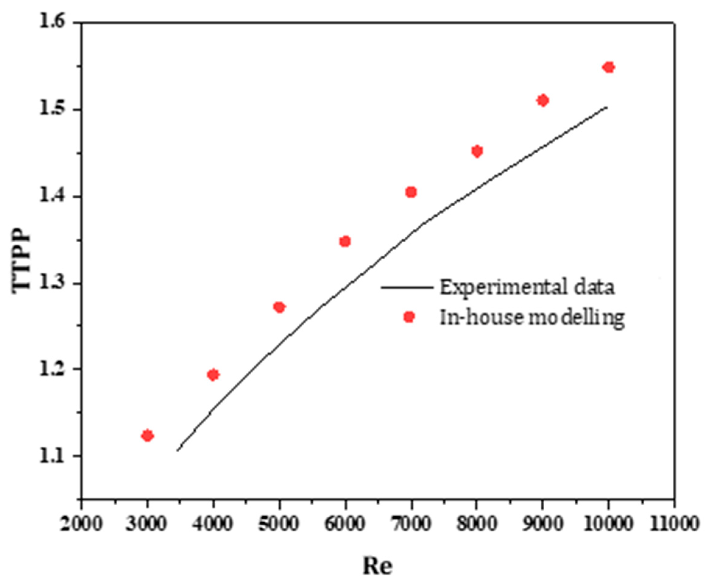
A comparison of the current results with the experimental data reported by Kabeel et al. [25] was used to verify the current model for the smooth SAH as shown in Figure 3. The maximum, minimum, and average errors were 8.91, 1.76, and 6.26%, respectively, all of which were acceptable. The RMSE value for the exit air temperature was 6.49%. The precision in measuring solar irradiance, ambient temperature, and wind speed, were all elements that contributed to such a notable difference between the numerical and experimental results and the accuracy with which optical characteristics were estimated as well as the assumptions employed to build the mathematical model. Subsequently, it was clear that the results were in good agreement with those of the published studies and that the present model can be applied in further investigations. The variation of the total thermal performance parameter (TTPP) for a rectangular SAH roughened by a V-down rib with Re for different attack angles (as reported by Istanto et al. [16]) was compared with the present work as depicted in Figure 4. The triangular channels used in this study had a greater TTPP than the rectangular channels used in the previous study, as seen in the figure. In addition, the trend for TTPP is the same in both graphs.

Figure 3.
Temperature difference across a smooth SAH versus daytime hours using our in-house model predictions and experimental data inferred from [25].

Figure 4.
TTPP versus Re based on our in-house predictions and experimental data inferred from [16].
3. Results
The useful energy, ηth, and ηt-th of SAH roughened by V-down ribs, which were calculated based on the numerical solution for numerous flow and roughness characteristics, are discussed below. To examine the improvement in useful energy, ηth, and ηt-th due to artificial roughness parameters, the findings were compared with those of smooth ducts operating under the same conditions.
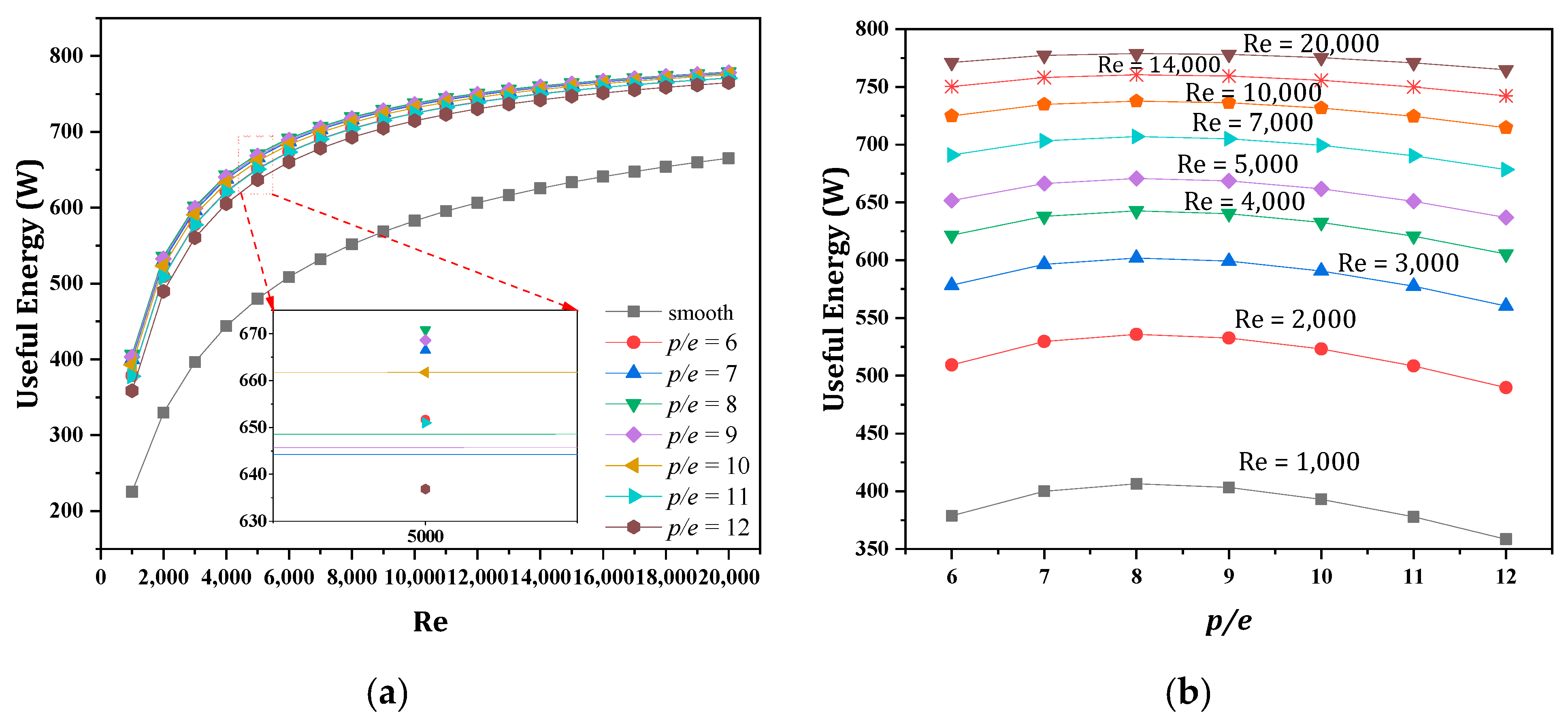
The effect of Re on the useful energy with various values of p/e and fixed values of α = 55°, e/D = 0.031, and W/w = 10 is depicted in Figure 5a. Clearly, useful energy rapidly increased when Re increased. It meant that as Re rose, the convective heat transfer coefficient rose as well. This might have been due to the flow slowing down, creating an unfavourable pressure gradient that increased instability, eddy formation, and flow separation at the protruded surface. As a result, significant energy loss from the heated surface was transferred to the working fluid. Figure 5a shows that the maximum heat gain for a SAH roughened by V-down ribs was 778.9 W, compared to 655.2 W for a smooth SAH and that the increase in heat gain became stable at increasing Re levels. As a result, higher Re (above 20,000) did not give an advantage to the thermal system; it merely added more pumping power. Figure 5b shows that useful gain increased at first, then dropped as p/e grew. At smaller values of p/e (<8), the convective heat transfer coefficient decreased. If the value of p/e increased beyond a certain point (p/e > 8), however, it may not have been able to break the laminar sub-layer to prevent the development of eddies and a reduced convective heat transfer coefficient.
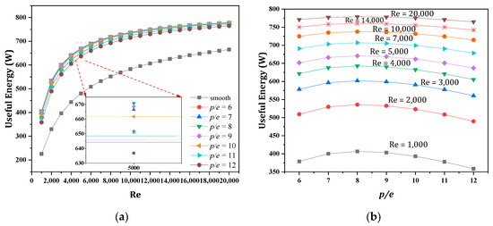
Figure 5.
Useful energy versus (a) Re at various pitch ratios (in the range of –) and (b) pitch ratios at various Re (1000–20,000).
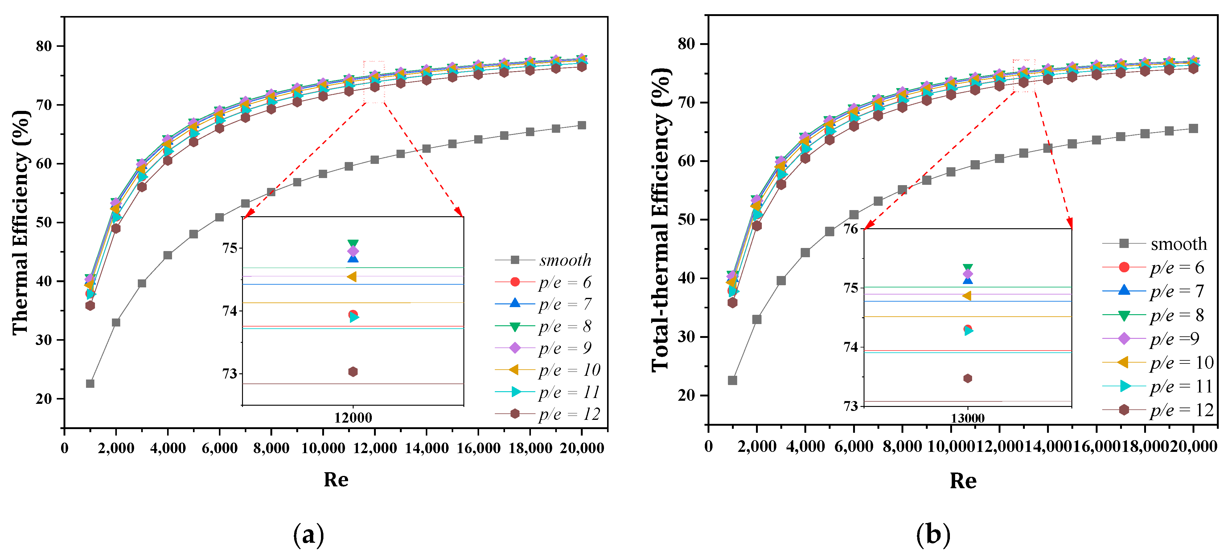
In Figure 6a, the influence of the V-down rib pitch ratio on SAH thermal efficiency was presented at fixed values of , , and for a wide range of Re. As it increased, the thermal efficiency increased fast as the heat gain rose. In addition, at high Re values, the gain in thermal efficiency became minimal with and without ribs. It was observed that the highest thermal efficiency for a roughened SAH was 77.9% compared to 66.5% for a smooth SAH. Essentially, in all thermal applications, including SAHs, maximum thermal efficiency and minimal pressure drop are required. Therefore, variations in specific parameters like useful gain and thermal efficiency did not clarify SAH thermal performance. As a result, hydrothermal efficiency, which combines improved thermal efficiency with increased pressure drop, was investigated. In Figure 6b, the total thermal efficiencies of SAH with and without V-down ribs are shown for a range of Re. In comparison to a smooth SAH, they were noticeably increased for all rib pitch ratios. According to the foregoing findings, the best total thermal efficiency was achieved at and .
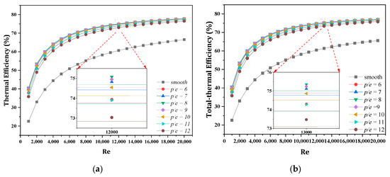
Figure 6.
Thermal (a) and total thermal (b) efficiencies versus Re for smooth and V-down rib roughened surfaces at various pitch ratios (in the range –).
Useful energy was investigated as a function of Re with various values of and the values of α = 55°, , and (see Figure 7). As can be seen from Figure 7, smaller ribs results in a significant increase in useful energy. When the rib height ratio rose, the augmentation became more noticeable. Due to intense turbulence induced in the main flow channel, which might have promoted mixing between the cold fluid and the heating surface, the increase in useful energy was noticeable at high Re values. Useful energy increased up to 1.18 times that for a smooth SAH. On the other hand, when the rib height ratio increased, the cross-sectional area of the flow channel was reduced, resulting in a larger pressure drop.
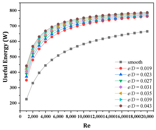
Figure 7.
Useful energy (W) versus Re for smooth and roughened surfaces at various relative roughness heights (in the range of –).
The influence of relative roughness height on thermal efficiency over a wide range of Re is presented in Figure 8. It shows that there was a considerable gain in thermal efficiency when the V-down ribs were used at the lowest Re value, and that this improvement enhanced the increasing relative roughness height . For a specific value of , this improvement was observed to be beneficial at a low Re and diminished with rising Re until it reached 20,000, at which point it remained unchanged. In addition, useful energy increased with an increment in Re, as seen in Figure 8a. As mentioned in the preceding section, this pattern was owing to the substantial breakdown of the laminar sub-layer at a high value of Re. The maximum increment in thermal efficiency was 16% which was obtained at Re = 20,000, and = 0.043. In Figure 8b, total thermal efficiency is shown against Re for all levels of relative roughness height. Greater efficiency was associated with higher relative roughness height and higher Re. The total thermal efficiency of a SAH with V-down rib at = 0.043 was 77.8%, compared to 65.6% for a smooth SAH at Re = 20,000. The best efficiency was found at Re = 20,000 and = 0.043, based on the above findings.
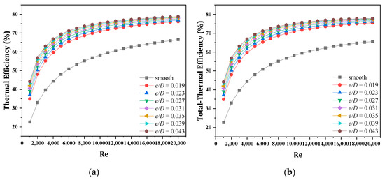
Figure 8.
Thermal (a) and total thermal (b) efficiencies versus Re at smooth and roughened surfaces various relative roughness heights (in the range of –).
The variations in useful energy as a function of angle of attack for various values of Re and the given values of , , and are shown in Figure 9a. For any given Re, useful energy rises as rises, peaking at 60°. Useful energy decreased as increased above 60°, but there was a value of for which useful energy reached its maximum. The presence of V-down ribs may cause flow separation as the movement of ensuing vortices combines to produce an optimal . Useful energy increased fast with an increase in , as seen in Figure 9b, and then progressively declined with higher values. The effect of on useful energy followed the same pattern as .
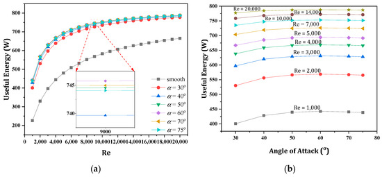
Figure 9.
Useful energy versus (a) Re at various angles of attack (in the range of –) and (b) angles of attack for various Re (in the range of –).
For a wide range of Re, Figure 10a shows the effect of the angle of attack on the thermal efficiency for fixed values of , , and . As Re rose, so did thermal efficiency as the heat gain increased. Furthermore, the improvement in thermal efficiency was limited at high Re values in all cases. It can be reported that the maximum thermal efficiency of 78.8% occurred at = 60° and Re = 20,000. Figure 10b illustrates how the total thermal efficiency varied with over a range of Re and was considerably higher for all angles of attack compared to the smooth SAH.
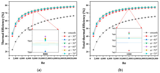
Figure 10.
Re at various angles of attack (in the range of –) versus the (a) thermal efficiency and (b) total thermal efficiency.
Based upon the above results, the optimal V-down rib parameters which gave maximum total thermal efficiency were , , and These parameters were examined theoretically for a SAH at Re = 20,000, and real weather conditions of Baghdad, Iraq (33.3° N, 44.4° E). Table 2 shows the values of insolation, ambient temperature, and wind velocity for a typical sunny day in January, which was taken from a local weather station.
Table 2.
Weather data of a typical sunny day in Baghdad city on 14 January 2021.
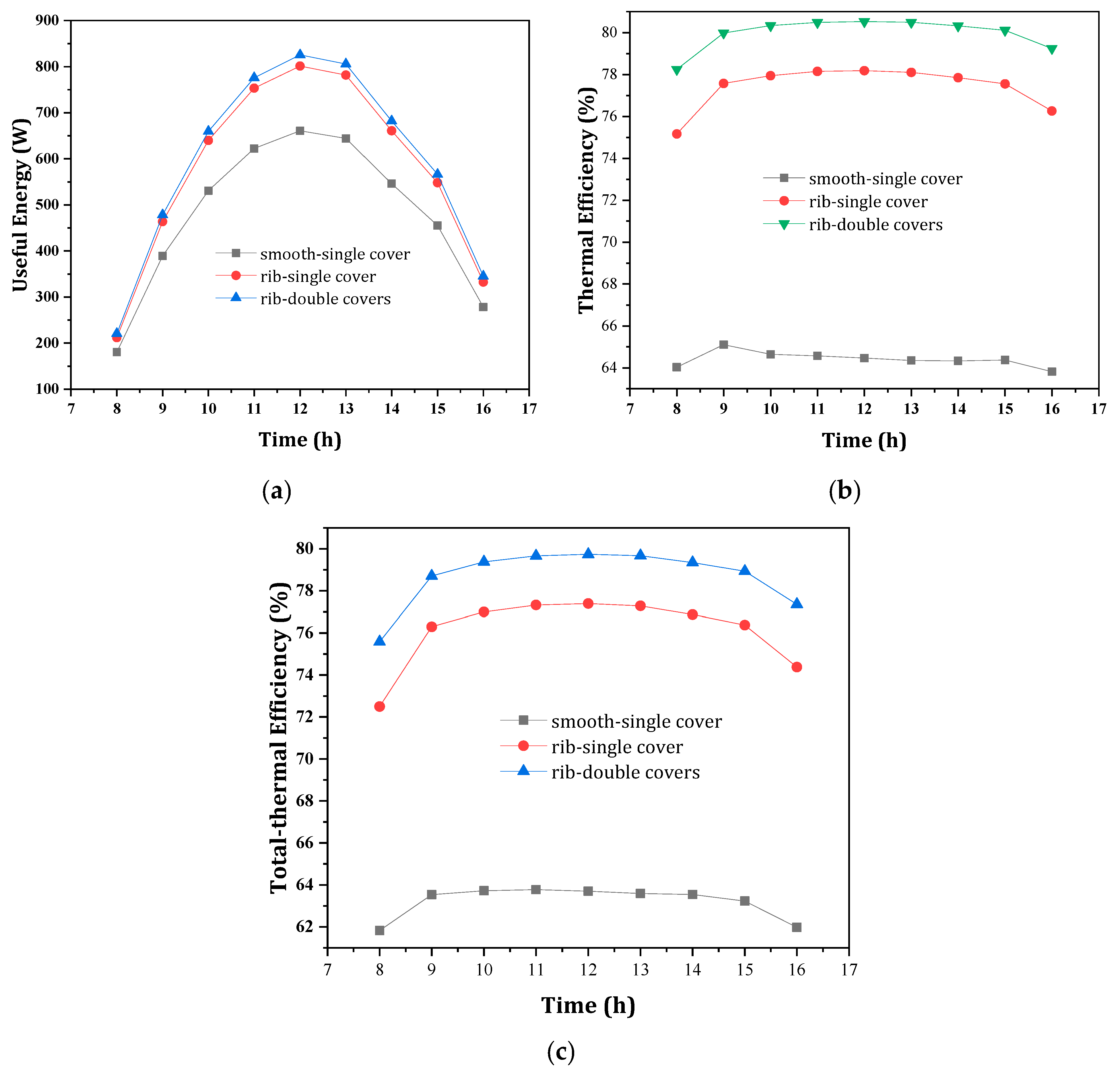
The influence of the optimal V-down rib parameters on the useful energy of SAH as a function of daytime is presented in Figure 11a. Clearly, from the latter figure the useful energy rose during the day, peaked at midday, and then fell in the afternoon. During the day, it fluctuated according to the insolation. The use of a double glass cover with rib roughness enhancement the useful heat gain even more. At noon, the maximum useful energy for a smooth SAH with a single cover, roughness with a single cover, and roughness with a double cover was 660.8, 801.4, and 825.4 W, respectively. Figure 11b shows the thermal efficiency of a SAH with and without ribs inside its channels as a function of daytime hours for single and double covers. The thermal efficiency improved for two hours after sunrise for all patterns and then remained relatively constant until one hour before sundown. The average thermal efficiency for a smooth SAH is 64.4%, but that can be increased to 77.5% by using ribs with a single cover. Furthermore, it could reach 80.0% by using ribs and double covers. A similar pattern is in Figure 11c for total thermal as well as thermal efficiency. The total thermal efficiency of SAH with ribs and single or double covers was 17.7 and 20.1%, respectively, higher than that of a smooth SAH.
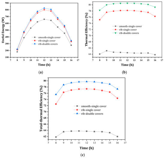
Figure 11.
Useful energy (a), thermal efficiency (b), and total thermal efficiency (c) versus daytime for smooth, V-rib roughened with single cover, and V-rib roughened with double cover SAH surfaces at Re = 20,000.
4. Conclusions
This work presented a detailed examination into the operating characteristics of Solar Air Heaters (SAHs), with V-down rib roughness on their absorber plates. The in-house model, based on the conjugation of heat transfer equations and system performance characteristics, was aimed at determining the best roughness parameters for optimal thermal efficiency. The primary findings of our study can be summarised as follows:
- Total thermal efficiency was found to be optimum at relative pitch p/e = 8, relative height e/D = 0.043, and angle of attack . The efficiency of SAH with V-down ribs was 15.7% higher than that of smooth SAH.
- The maximum thermal efficiency of a SAH roughened by V-down ribs is 78.8%, compared with 66.5% for that of a smooth SAH.
- The maximum V-down roughened SAH thermal efficiency was 78.8%, predicted under steady-state conditions of Re = 20,000, solar irradiance G = 1000 W/m2, p/e = 8, e/D = 0.043, and = 60. That is about 1.18 times more efficient than for a smooth surface SAH.
- Under actual weather conditions, the total thermal efficiencies of a SAH with V-down ribs was up to 17.7% when using a single cover and 20.1%, when using a double cover, which were higher than for a smooth SAH.
- The results were in good agreement with published studies having a maximum percentage error of 8.91%.
In conclusion, the use of V-down ribs made a significant improvement to system performance. However, an economic drawback of this system is the provision of such a design and raw material. In our system, we used waste cans and manufactured the ribs using our in-house folders. Different designs can be adapted based on the manufacturing tools and waste material availability.
Author Contributions
M.A.: Methodology, Software, Validation; A.M.K.: Visualization, Investigation; A.A.F.: Conceptualisation, Writing—Original draft preparation, Super-vision; M.A.-D.: Writing—Review and Editing; M.A.Q.: Writing—Reviewing and Editing, Data curation. All authors have read and agreed to the published version of the manuscript.
Funding
This research received no external funding.
Institutional Review Board Statement
Not applicable.
Informed Consent Statement
Not applicable.
Conflicts of Interest
The authors declare no conflict of interest.
Nomenclature
| Ap | projection area | m2 |
| b | half-height of v-corrugated duct | m |
| Cf | energy conversion factor | - |
| specific heat capacity of air | J/kg K | |
| hydraulic diameter | ||
| e/D | relative roughness height | - |
| f | friction factor | - |
| convective heat transfer coefficient | W/m2 K | |
| radiative heat transfer coefficient | W/m2 K | |
| hw | convective heat transfer coefficient of wind | W/m2 K |
| G | Solar irradiance | W/m2 |
| L1 | length of the collector | |
| L2 | width of the collector | |
| ṁ | mass flowrate | kg/s |
| Nu | Nusselt number | - |
| relative roughness pitch | - | |
| Pm | power consumption | W |
| Qu | useful energy | W |
| Re | Reynolds number | - |
| T | temperature | K |
| ti | thickness of insulation | m |
| Ub | coefficient of bottom heat loss | W/m2 K |
| Ut | coefficient of top heat loss | W/m2 K |
| Vw | wind speed | m/s |
| W | width of absorber plate | m |
| Greek letters | ||
| angle of attack | ° | |
| absorptivity of absorbing plate | - | |
| β | tilted angle of collector | ° |
| σ | Stefan–Boltzmann constant | W/m K4 |
| ρa | density of air | kg/m3 |
| λ | thermal conductivity | W/m K |
| μa | viscosity of air | Pa s |
| ηt-th | total thermal efficiency | % |
| ηth | thermal efficiency | % |
| ε | emittance | - |
| τc | transmissivity of the glass cover | - |
| ΔP | pressure drop | Pa |
| Subscripts | ||
| a | Air | |
| ai | inlet air | |
| am | ambient air | |
| ao | outlet air | |
| b | Backplate | |
| b-a | backplate to air | |
| i | Insulation | |
| p | absorber plate | |
| p-a | absorber plate to air | |
| p-b | absorber plate to bottom plate | |
Appendix A. Solution Algorithm
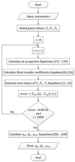
Figure A1.
Flowchart of the summarised logic algorithms of the in-house code.
Figure A1.
Flowchart of the summarised logic algorithms of the in-house code.
References
- Al Qubeissi, M.; El-kharouf, A.; Soyhan, H.S. Renewable Energy-Resources, Challenges and Applications, 1st ed.; IntechOpen: London, UK, 2020. [Google Scholar] [CrossRef]
- Al-Damook, M.; Abid, K.W.; Mumtaz, A.; Dixon-Hardy, D.; Heggs, P.J.; Qubeissi, M.A. Photovoltaic module efficiency evaluation: The case of Iraq. Alex. Eng. J. 2021, 61, 6151–6168. [Google Scholar] [CrossRef]
- Hasan, D.J.; Farhan, A.A. The Effect of Staggered porous fins on the performance of Photovoltaic panel in Baghdad. J. Eng. 2020, 26, 8. [Google Scholar] [CrossRef]
- Al-Damook, M.; Obaid, Z.A.H.; Al Qubeissi, M.; Dixon-Hardy, D.; Cottom, J.; Heggs, P.J. CFD modeling and performance evaluation of multipass solar air heaters. Numer. Heat Transfer. Part A Appl. 2019, 76, 438–464. [Google Scholar] [CrossRef]
- Sahu, M.K.; Matheswaran, M.M.; Bishnoi, P. Experimental investigation of augmented thermal and performance characteristics of solar air heater ducts due to varied orientations of roughness geometry on the absorber plate. Arch. Thermodyn. 2020, 41, 147–182. [Google Scholar] [CrossRef]
- Nidhul, K.; Yadav, A.K.; Anish, S.; Kumar, S. Critical review of ribbed solar air heater and performance evaluation of various V-rib configuration. Renew. Sustain. Energy Rev. 2021, 142, 110871. [Google Scholar] [CrossRef]
- Singh, V.P.; Jain, S.; Gupta, J. Analysis of the effect of perforation in multi-v rib artificial roughened single pass solar air heater: Part A. Exp. Heat Transf. 2021, 1–20. [Google Scholar] [CrossRef]
- Farhan, A.A.; Sahi, H.A. Energy Analysis of Solar Collector With perforated Absorber Plate. J. Eng. 2017, 23, 89–102. [Google Scholar]
- Hans, V.S.; Saini, R.; Saini, J. Performance of artificially roughened solar air heaters—A review. Renew. Sustain. Energy Rev. 2009, 13, 1854–1869. [Google Scholar] [CrossRef]
- Al-Damook, M.; Khatir, Z.; Al Qubeissi, M.; Dixon-Hardy, D.; Heggs, P.J. Energy efficient double-pass photovoltaic/thermal air systems using a computational fluid dynamics multi-objective optimisation framework. Appl. Therm. Eng. 2021, 194, 117010. [Google Scholar] [CrossRef]
- Prasad, B.; Kumar, A.; Singh, K. Optimization of thermo hydraulic performance in three sides artificially roughened solar air heaters. Sol. Energy 2015, 111, 313–319. [Google Scholar] [CrossRef]
- Lanjewar, A.; Bhagoria, J.; Sarviya, R. Heat transfer and friction in solar air heater duct with W-shaped rib roughness on absorber plate. Energy 2011, 36, 4531–4541. [Google Scholar] [CrossRef]
- Hans, V.; Saini, R.; Saini, J. Heat transfer and friction factor correlations for a solar air heater duct roughened artificially with multiple v-ribs. Sol. Energy 2010, 84, 898–911. [Google Scholar] [CrossRef]
- Momin, A.-M.E.; Saini, J.; Solanki, S. Heat transfer and friction in solar air heater duct with V-shaped rib roughness on absorber plate. Int. J. Heat Mass Transf. 2002, 45, 3383–3396. [Google Scholar] [CrossRef]
- Jin, D.; Quan, S.; Zuo, J.; Xu, S. Numerical investigation of heat transfer enhancement in a solar air heater roughened by multiple V-shaped ribs. Renew. Energy 2018, 134, 78–88. [Google Scholar] [CrossRef]
- Istanto, T.; Danardono, D.; Yaningsih, I.; Wijayanta, A.T. Experimental study of heat transfer enhancement in solar air heater with different angle of attack of V-down continuous ribs. AIP Conf. Proc. 2016, 1737, 060002. [Google Scholar] [CrossRef]
- Karwa, R.; Bairwa, R.D.; Jain, B.P.; Karwa, N. Experimental Study of the Effects of Rib Angle and Discretization on Heat Transfer and Friction in an Asymmetrically Heated Rectangular Duct. J. Enhanc. Heat Transf. 2005, 12, 343–355. [Google Scholar] [CrossRef]
- Farhan, A.A.; Ali, A.I.M.; Ahmed, H.E. Energetic and exergetic efficiency analysis of a v-corrugated solar air heater integrated with twisted tape inserts. Renew. Energy 2021, 169, 1373–1385. [Google Scholar] [CrossRef]
- Duffie, J.A.; Beckman, W.A.; Blair, N. Solar Engineering of Thermal Processes, Photovoltaics and Wind, 5th ed.; John Wiley & Sons, Inc.: Hoboken, NJ, USA, 2020. [Google Scholar]
- Malhotra, A.; Garg, H.P.; Palit, A. Heat loss calculation of flat plate solar collectors. J. Therm. Eng. 1981, 2, 59–62. [Google Scholar]
- Hedayatizadeh, M.; Ajabshirchi, Y.; Sarhaddi, F.; Farahat, S.; Safavinejad, A.; Chaji, H. Analysis of exergy and parametric study of a v-corrugated solar air heater. Heat Mass Transf. 2012, 48, 1089–1101. [Google Scholar] [CrossRef]
- Hollands, K.G.T.; Shewen, E.C. Optimization of Flow Passage Geometry for Air-Heating, Plate-Type Solar Collectors. J. Sol. Energy Eng. 1981, 103, 323–330. [Google Scholar] [CrossRef]
- Gao, W.; Lin, W.; Liu, T.; Xia, C. Analytical and experimental studies on the thermal performance of cross-corrugated and flat-plate solar air heaters. Appl. Energy 2007, 84, 425–441. [Google Scholar] [CrossRef]
- Hussien, S.Q.; Farhan, A.A. The effect of metal foam fins on the thermo-hydraulic performance of a solar air heater. Int. J. Renew. Energy Res. 2019, 9, 840–847. [Google Scholar] [CrossRef]
- Kabeel, A.; Khalil, A.; Shalaby, S.; Zayed, M. Experimental investigation of thermal performance of flat and v-corrugated plate solar air heaters with and without PCM as thermal energy storage. Energy Convers. Manag. 2016, 113, 264–272. [Google Scholar] [CrossRef]
- Moriasi, D.N.; Arnold, J.G.; van Liew, M.W.; Bingner, R.L.; Harmel, R.D.; Veith, T.L. Model evaluation guidelines for systematic quantification of accuracy in watershed simulations. Trans. ASABE 2007, 50, 885–900. [Google Scholar] [CrossRef]
- Taha, S.Y.; Farhan, A.A. Performance augmentation of a solar air heater using herringbone metal foam fins: An experimental work. Int. J. Energy Res. 2020, 45, 2321–2333. [Google Scholar] [CrossRef]
- Al-Damook, M.; Dixon-Hardy, D.; Heggs, P.J.; Al Qubeissi, M.; Al-Ghaithi, K.; Mason, P.E.; Cottom, J. CFD analysis of a one-pass photovoltaic/thermal air system with and without offset strip fins. In MATEC Web of Conferences; EDP Sciences: Les Ulis, France, 2018; Volume 240, p. 03002. [Google Scholar] [CrossRef]
Publisher’s Note: MDPI stays neutral with regard to jurisdictional claims in published maps and institutional affiliations. |
© 2022 by the authors. Licensee MDPI, Basel, Switzerland. This article is an open access article distributed under the terms and conditions of the Creative Commons Attribution (CC BY) license (https://creativecommons.org/licenses/by/4.0/).