Article

Integration of NDT to Assess Composite Contemporary Artworks Made on Photosensitized Cement

by
Eugenia Stamatopoulou
,
Maria Karoglou
and
Asterios Bakolas
*
Laboratory of Materials Science and Engineering, School of Chemical Engineering, National Technical University of Athens, 9 Iroon Polytechniou Street, Zografou, 15780 Athens, Greece
*
Author to whom correspondence should be addressed.
Heritage 2023, 6(12), 7261-7276; https://doi.org/10.3390/heritage6120381
Submission received: 30 September 2023 / Revised: 12 November 2023 / Accepted: 17 November 2023 / Published: 21 November 2023
(This article belongs to the Section Materials and Heritage)

Abstract

:
Non-destructive techniques (NDT) have enhanced their usefulness in the field of cultural heritage protection and have become valuable tools for the investigation of composing materials, as well as for the detection of alteration and degradation of various structures. In the current study, non-destructive techniques, based on digital photography processing and analysis (digital photography-Vis/UVF, portable digital optical microscopy, colorimetry, infrared thermography), are used for the examination of three composite contemporary artworks created on photosensitized cement. This approach was applied to a series of composite works (photosensitized cement surfaces) in order to understand the craftmanship of the artist, document the materials used and assess the overall condition of the artworks. The techniques and methods applied can be used as a benchmark for the study of similarly complex artworks and for conservation and restoration planning. This comparative study has shown that, although the three artworks under examination are composed of alike materials (cement mortar, plaster, photosensitive emulsion), they exhibit distinct condition states, which can be attributed to variations in the artist technique and application, as well as to their exposure to different environmental conditions.

1. Introduction

Contemporary artistic creation is characterized by the use of a variety of new materials and applications, which in some cases are inherently unstable and therefore exhibit various types of alterations and defects that lead to a general deterioration of the artwork.
A first approach to this topic is the study of these complex contemporary artworks using non-destructive techniques (NDTs). The aim is to evaluate their materials and processes of creation and to provide a broader and deeper knowledge of the craftsmanship and technology used by modern artists [1].
NDTs have been used for several years as a tool for the examination of works of art [2,3,4]. The techniques most commonly used for this purpose are those that utilize different wavelength ranges of the electromagnetic spectrum (visible and non-visible range) to detect the different layers (surface and subsurface) of a composite artwork based on imaging techniques [5]. Depending on the information needs, NDTs can be combined with microdestructive techniques to obtain additional information about the artwork materials (micro-Fourier Transform Infrared Spectroscopy (FTIR), micro-Raman spectroscopy, X-ray fluorescence spectrometry (XRF), gas chromatography–mass spectrometry (GC–MS), liquid chromatography–mass spectrometry (HPLC–MS)) [6]. Most of these techniques can be applied in situ and provide direct information by making it possible to determine the original materials and their properties in a simple and quick way and to detect the presence of alterations and their effects on the physical condition of an object [7,8].
They can also help to determine the factors that may influence conservation treatment and assist in the evaluation of ongoing treatment.
Depending on the artwork to be examined, its dimensions and ease of access, as well as the complexity of the composite materials, a standard examination using NDTs can be used as a tool in the conservation process [9,10]. These can be easily applied by conservators and scientists and used as a benchmark for the documentation of composite artworks, such as contemporary artworks, to gain a better understanding of the artist’s technique and materials of choice.
In this framework, three artworks by the Greek contemporary artist Nikos Kessanlis (1930–2004), created on photosensitized cement, are examined in situ using imaging techniques and documentation (Vis-UVF), colorimetry and active and passive infrared thermography to document and evaluate the materials of which they are composed and to determine their condition. In addition, microanalyses of the samples are carried out using micro-Raman spectroscopy and SEM-EDX microscopy [11].
The aim of this study is to explore the craftsmanship of Nikos Kessanlis and to assess the condition of the materials of these unique artworks in terms of their composition as well as their exposure to different environmental conditions. Ultimately, the aim is to obtain the necessary information for the development of a plan that will ensure the long-term conservation of these works of art.

2. Materials and Methods

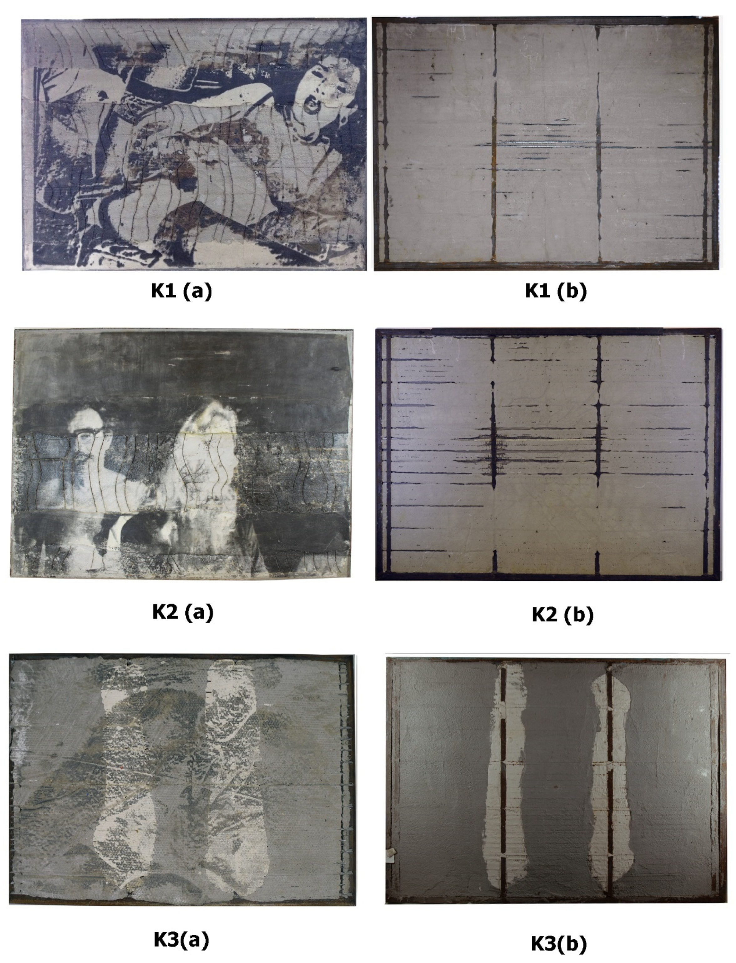
2.1. Description of the Artworks

The artworks examined in this study were deliberately chosen as an excellent case study for NDT investigation. The selection was based on their complex and unconventional combination of materials (such as cement mortar, plaster, metal, photographic print), as well as their varying condition states.
Nikos Kessanlis is an internationally recognized Greek artist who, as one of the members of Mec-Art group, experimented with his work on various applications of photomechanical techniques, focusing mainly on creating artworks using only mechanical media [12].
The artist’s creative line is based on older techniques and their evolution, reusing them in a new context [13,14].
For the creation of these artworks made on photosensitized cement, the artist worked with a technique called “alternative printing process”. This technique is based on the application of a silver-composed sensitizer (liquid emulsion) on a support (such as paper, canvas, concrete, plaster, metal, and others), where the image is exposed using an enlarger, contact printing, or a slide projector. The sensitizer then is processed in the same way as it is in traditional photography. Alternative photography printing represents a unique creative process, because it offers the opportunity to experience and transform two-dimensional printing and extends the photographic medium into the third dimension [15,16]. The commonly used sensitizer is a commercially prepared mixture of a light-sensitive colloid found in film-based photography. Frequently, it is composed by silver halide crystals dispersed in gelatin (silver chloride (AgCl) or silver bromide (AgBr)). The sensitizer is then processed with the use of a developer containing an organic compound as agent (the two most frequently encountered developing agents are Metol (C7H10NO)2SO4) and hydroquinone (C6H4(OH)2) and a fixing agent (popular agents are the Hypo (Na2S2O3) and the rapid fixer (NH4)2S2O3).
The final image results strongly depend on how this photosensitive emulsion is applied to the support and on the nature of the surface (absorbent, non-absorbent, smooth or rough). It is very sensitive in the preparation phase, as it must be applied warm and evenly with brushes, rollers or spray guns. Also, the use of inadequate tools during the warming of the emulsion, such as tools made of steel or brass, may contaminate the mixture, and create discoloration spots on the final image [17,18].
If the coating is applied unevenly to the substrate, spots may appear on the final image. On the other hand, the excessive use of a large amount of sensitizer leads to swelling of the binder (gelatin) during processing and finally to its cross-linking in the drying phase [19]. Furthermore, an excess of photosensitive emulsion, if the wash baths are not well processed, leaves photosensitive residues that cause localized yellow-brownish areas [20]. Finally, if the support is made of absorbent materials and the surface is not sealed, the developer may be absorbed, resulting in a certain type of yellow-greenish stain. Sealing of an absorbent surface can be made by using either a primer (a polymeric coating or varnish) or a ground [21].
The present study examines three works of art created by the use of a light-sensitive emulsion coated on cement and plaster. The artworks titled “Erotica” (K1), “The Couple” (K2) and “Untitled” (K3) were all created in 1996. Two of them (K1 and K2) were made so as to participate in the exhibition “Cements”, in Athens (1996) [22]. All three artworks have similar dimensions (110 × 150 × 3 cm) and depict black and white images developed on a support composed of cement mortar and white plaster, previously coated with a light-sensitive emulsion (Figure 1a,b).
The cement mortar support has a thickness of approximately 1.5 cm and is mixed with limestone aggregates [23]. It is framed by a metallic construction and mesh and bars imbedded in the support are partially visible on the backside (Figure 1(K1b–K3b)).
The artworks K1 and K2 are covered on the front side over the cement mortar support with two layers (upper and lower part) of white plaster of ~0.5 cm thickness, while K3 was made only with a grey cement mortar support in which two different areas of cement mortar on a white base are embedded (Figure 1(K1a–K3a)). In addition, the face of K1 and K2 is locally deeply scratched to simulate the way walls are treated to emphasize their bonding ability (Figure 1(K1a,K2a)). Macroscopic examination revealed the different condition state of each artwork. K1 presents various areas exhibiting loss of the photographic layer, as well as extended discoloration (yellowish-brownish spots) (Figure 1(K1a)). K2 presents some exfoliations and a diffused yellow brownish tone at the image layer, located especially at the center and edges of the work (Figure 1(K2a)). Finally, K3 the image depicted is largely faded, and the surface is patterned with round impressions in a regular position (Figure 1(K3a)). Since their creation, the three artworks were preserved and displayed in different environments. K1 was part of a private collection and was exhibited for several years in a summer house on a Greek island, where it was exposed to high humidity and light; it was also damaged in a fire. K2 was stored in the artist’s house and has been kept inhabited and locked away since 2003. Finally, K3 was stored in an external environment in the artist’s studio courtyard, where environmental conditions such as temperature, humidity and lighting were completely uncontrolled. Although, the three artworks are created with similar materials and using the same technique, they have obvious differences in terms of their preservation state. This is mainly due to the fact that they are exposed to different environmental conditions. As expected, the artworks exposed to the most unstable and extreme environmental conditions, K1 and K3, appear to show greater damage (flaking, loss, fading).

2.2. Non-Invasive Imaging Techniques

2.2.1. Visible Light (VIS)

The artworks’ surface morphology and condition are first examined and documented using macro- and microphotography, with a digital single-lens reflex camera (NikonD70, with a macro-AF-S Nikon 3.5–4.5 G ED and micro-Nikkor 60/F2.8 D lenses) under visible light. For this, two fluorescent lamps (Kandolight, Energy Saving, T8, 36W/86, White, 60–69 CRI, 2800 K, 1200 lumen, 150 cm length) are used, placed at both side of the artwork and illuminating the surface at 45° angle from a distance of 60 cm.

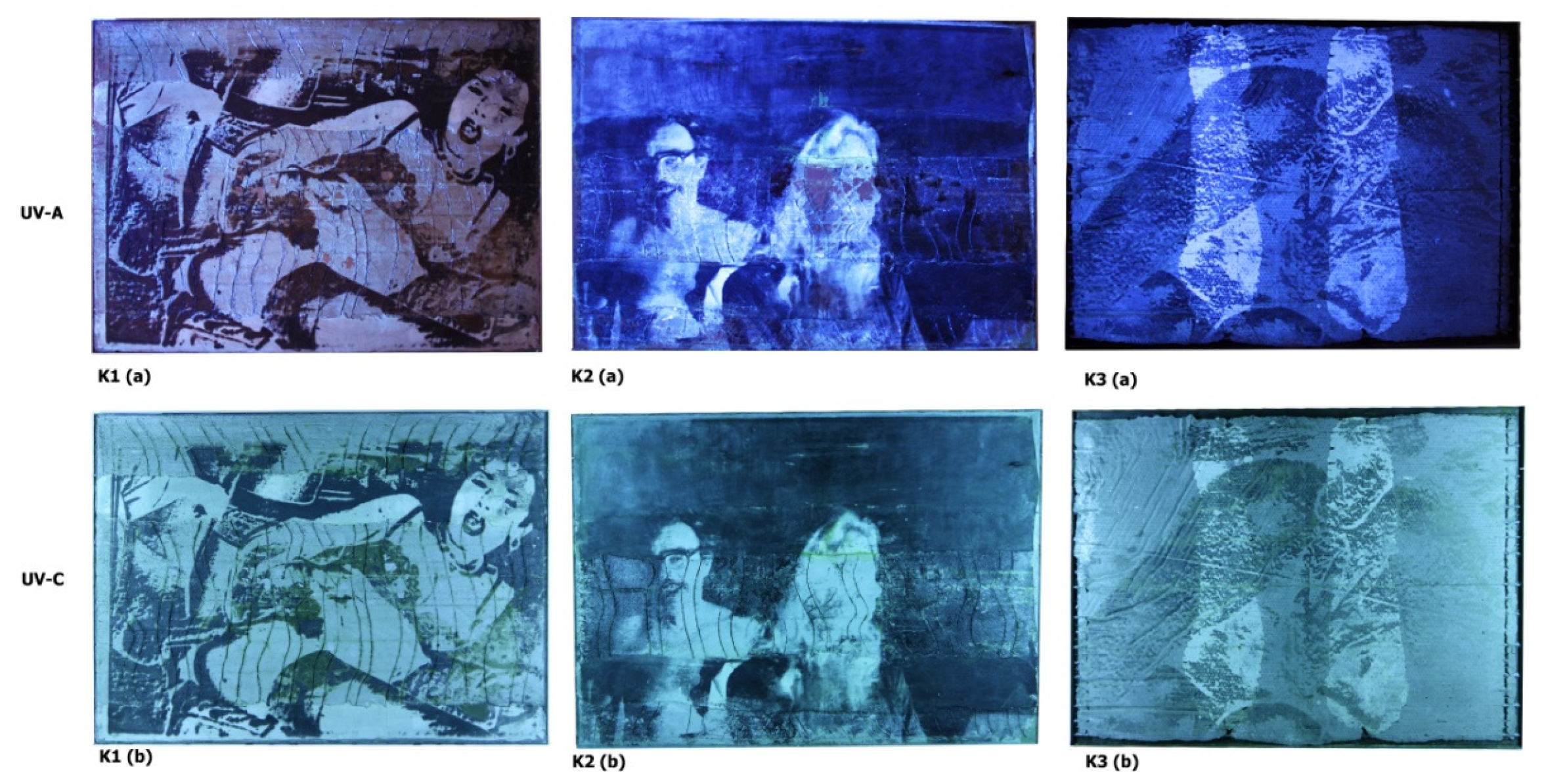
2.2.2. UV-Induced Visible Fluorescence Imaging (UVF Imaging)

Ultraviolet-induced visible fluorescence imaging-based examination is a fundamental analysis technique that can be used to document the conservation status of a surface and to localize materials emitting characteristic radiation, in form of fluorescence, in the visible wavelength range under ultraviolet radiation [24,25,26]. The images are used to study the distribution of luminescent materials such as organic binders and dyes. Some inorganic materials also show luminescent properties, such as some inorganic pigments including zinc oxide with impurities. The absence of luminescence does not mean that organic materials are not present.
For this technique, two separate sets of lamps, with different wavelength emission, were used; a set of UV-A at 300–400 nm (OSRAM SUPRATEC L 36W 73 G13 BLB Black light) and a set of UV-C at 254 nm (PHILIPS TUV 36 TUV PL-L 36W/4), all of 150 cm length. To provide an even wash of radiation across the surface the lamps were positioned at an angle of 45°, on a distance of 60 cm. All visible light sources are eliminated (dark room) and the image is captured with a digital CCD camera (Canon EOS 500D with a Nikon EF-S, 18–55 mm lens) with a Haze-2A filter.

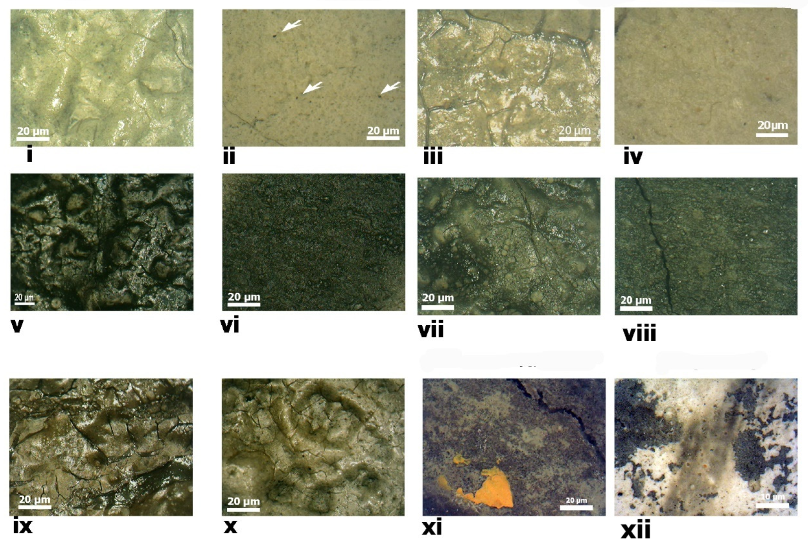
2.2.3. Optical Portable Microscopy

Microscopic examination is achieved with the use of a portable digital optical microscope, consisting of an array of led optical lenses (I-Scope, Moritex), using a magnification of ×30, ×50, ×120. The scope is equipped with a 1.3 mega CMOS (Complementary Metal-Oxide Semiconductor) sensor that, matched to the lenses, provides high quality imaging. To illuminate the surface for imaging, white LEDs are integrated into the housing of the sensor. The scope also features highly uniform lighting and color accuracy as a result of each scope being calibrated to ensure even illumination.

2.2.4. Colorimetry

Colorimetric measurements are carried out by light absorption in diffuse reflection, using a portable spectrophotometer (Dr Lange spectrocolor LMG 183), with a resolution of 10 nm and accuracy of ± 0.01. All measurements are carried out in an environment with 22 °C and 55% RH. Color values were measured using the CIELab (1976) color space and results are compared according to EN 15886:2010 [27,28,29].
The surface areas of K1, K2 and K3 artworks were divided into sections of 10 × 10 cm, and 6 to 10 accumulations were acquired from each section.
The color of each section is determined by the three coordinates, L*, a* and b*. Coordinate L* (neutral axis) corresponds to grades of lightness from 0 (black) to 100 (white), coordinate a* is based on the green/red axis (negative values represent the green component and positive values the red component), and coordinate b* refers to the blue/yellow axis (negative values representing the blue component and positive values the yellow component). The hue (H*) value is correlated to the chromatic tonality and corresponds to the metric hue angle between a* and b* values (where 90° correspond to yellow, 180° to bluish-green and 270° to blue) and can be calculated by Equation (1). Additionally, saturation (C*) is the metric chroma, corresponding to the absolute value of a* and b* coordinates, and is calculated by Equation (2) [30].
H = a r c tan ( b a )
C = a 2 + b 2

2.2.5. Infrared Thermography

In order to identify all subsurface characteristics and invisible areas of decay and defects, the front and back of the three artworks were examined using passive and active infrared thermography.
For the thermographic investigation, the capture of the emitted image was accomplished using an infrared camera (FLIR, B200, Western, Agema, Malmö, Sweden, 7.5–13 µm) employing two different lenses (25° and 45°) and from a distance of 30–40 cm, maximum. For the active infrared thermography, the artworks were externally stimulated with the use of an infrared lamp (MODEL SRU-1624 SERIA 1298, Infratech Corporation, Oslo, Norway, 1500 W), at a distance of 50 cm and at a room temperature of 20 °C. Coefficient of emissivity for the materials was set at 0.85. The heating of the surface was fifteen minutes in total and the thermal images were captured during the cooling stage.

2.2.6. Raman and SEM-EDX

Microsamples are obtained from the three artworks in distinct locations, with different tones and defects and on cement and mortar support. The micromorphology and distribution of the elemental component in the samples is analyzed by means of an FEI/Philips, Quanda 200 scanning electron microscope (SEM) coupled with a spectrometer for elemental analysis based on X-ray energy system (EDX).
Additionally, Raman spectroscopic study was carried out with a microscope system (in Via, Renishaw) that enables users to analyze samples with uneven, curved or rough surfaces. The system is coupled with an optical confocal microscope with transmitted and reflected light, notch filters and a thermoelectrically cooled charged-coupled device (CCD) detector, using a 785 nm laser line for excitation. The laser beam was focused on different areas of the samples and on both sides (recto and verso) using an ×20 objective. Density filters were used to set the laser power at 1% for an exposure time of 10 s. A 1200 lines/mm grating was used, and in each spot, 3 scans were acquired for a wavelength range between 100 and 3500 shifts/cm−1.

3. Results and Discussion

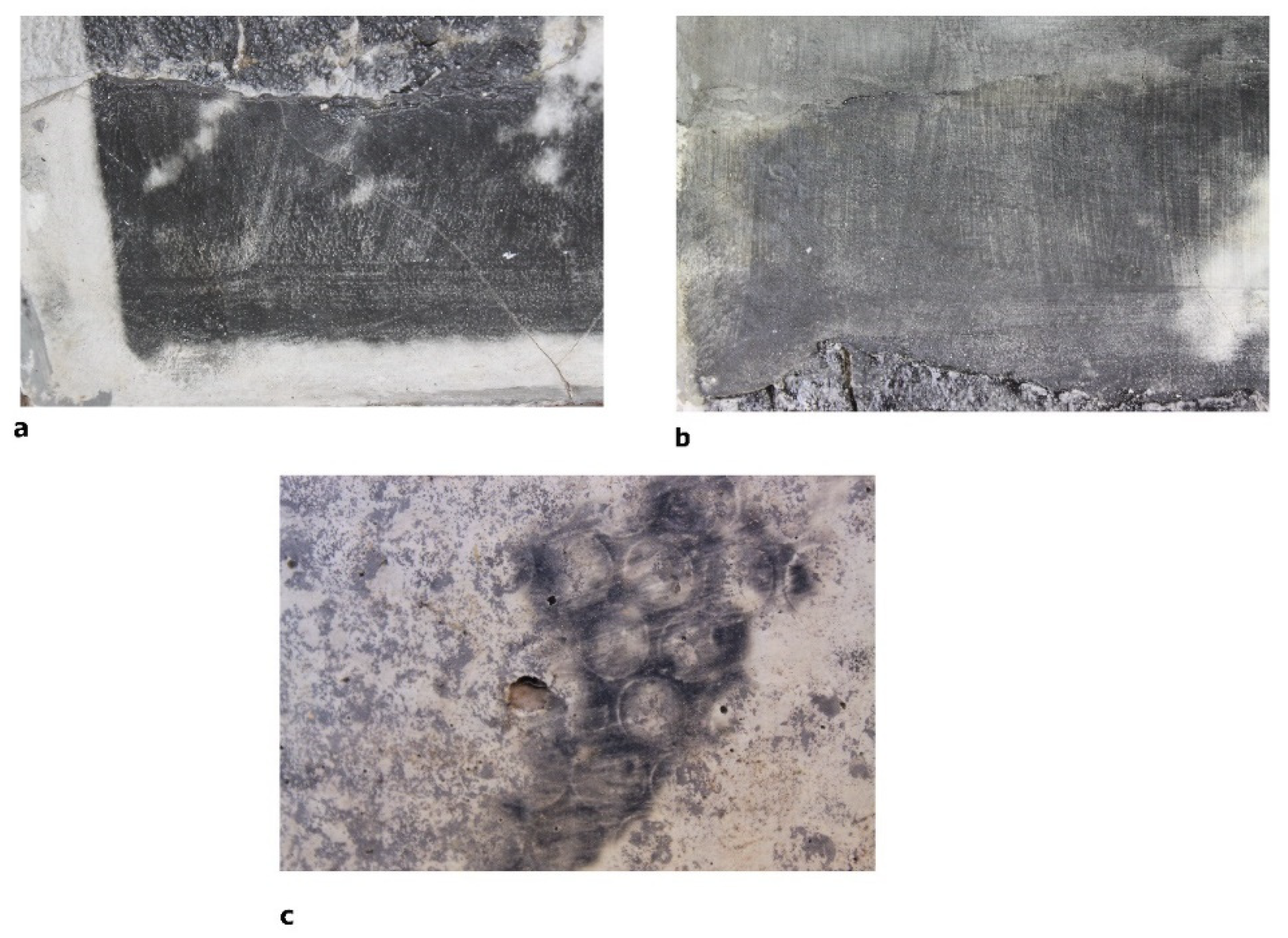
3.1. Visible Light Imaging

Imaging techniques are very useful non-destructive tools for obtaining the representation of certain physical properties and characteristics of a surface, by direct or magnified observation, using a variety of sources and angles of illumination.
This examination can provide an overall record of the materials and structure composing an artwork and offers important information about its condition.
In the case of artworks K1 and K2, examination using digital macro- and microphotography with visible light revealed an uneven front surface with rough cement mortar and smoother layers of plaster (Figure 1(K1a,K2a)).
In these two artworks, the brushstrokes used to apply the emulsion and the artist’s hand movement are easily recognizable on the smoother surfaces (plaster layer), especially where the tone is darker (black and grey tones) (Figure 2a,b).
On the other hand, the characteristics of the support of artwork K3 are quite different. It shows a grooved cement mortar surface (grey and white) covered with round impressions (Figure 1(K3a)). The shape of these impressions corresponds to the pattern of bubble wrap, which the artist probably used after applying the wet emulsion to the support and before working on the development of the photographic image (Figure 2c).
Examination of the backs of all three artworks revealed an uneven surface with vertical and laterally integrated metal elements as well as a metal grid embedded in the cement mortar (Figure 1(K1b–K3b)). The metal parts show signs of corrosion, which can be seen on the back and in some areas on the front of the works (Figure 3a–f).

3.2. Ultraviolet Induced Visual Fluorescence Imaging

The fluorescence of the surface of works of art under long-wave (UV-A) and short-wave (UV-C) ultraviolet radiation provides information about the diversity of the materials used by the artist and their degradation products [31]. For example, the areas where the photographic emulsion is absent fluoresce under a long-wavelength lamp, whereas they show a bluish fluorescence under a short-wavelength lamp (Figure 4(K1b–K3b)) [32,33]. In particular, areas that are yellow-brown in visible light show a very bright yellow fluorescence under UV-C, while under UV-A they show a dull violet color (Figure 4(K1a–K3a)).
The UV-A images of K1 and K2 show that both artworks suffer from losses on their emulsion, either on the concrete mortar or on the plaster surface. In addition, the color tones of the surface of K3 become more intense at this wavelength and it is easier to read the image shown (Figure 4(K1a–K3a)). Finally, UV-C images show areas (localized in K1 and K2 and extended in K3) with yellow-greenish tone (Figure 4(K1b–K3b)).
Areas that are not covered by the photographic emulsion with a mid-violet fluorescence under UV-A may correspond to the presence of calcium carbonate on cement and plaster [34]. The darker areas on the K2 artwork, when examined with the UV-A lamp, are related to the materials used to paint over the damage. They were probably made with carbon pigments or black ink, both of which absorb UV light and appear blue-black [35].
Finally, areas that fluoresce yellow under UV-C can be attributed to the presence of silver sulfate (Ag2S), which is a decomposition product of the silver gelatin image during image development [15].

3.3. Digital Optical Microscopy
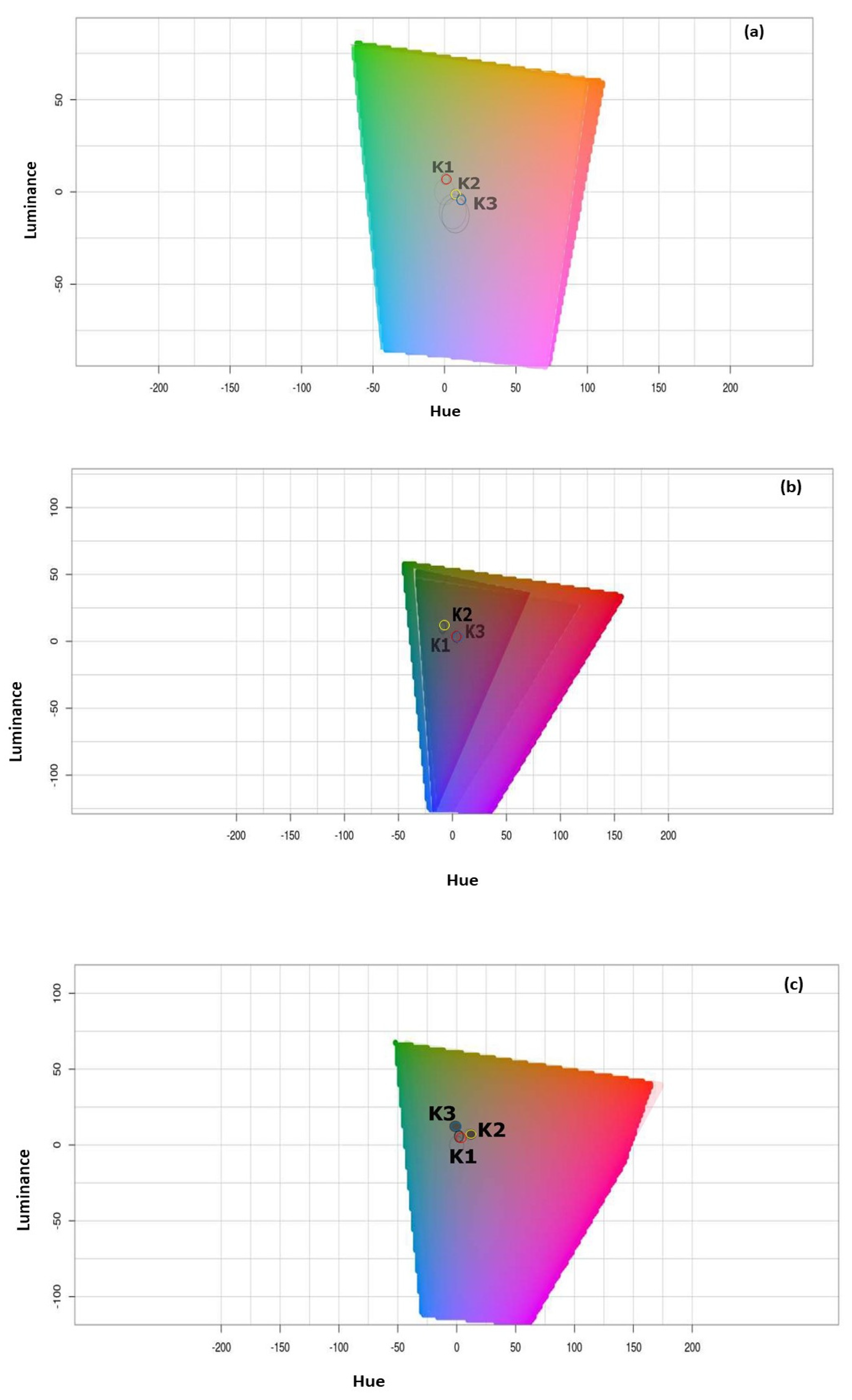
The surface documentation of the three works of art using digital microscopy revealed characteristic defects. With regard to the location of the defects in relation to the surface of the artwork, they can be divided into subsurface and internal defects (structural) and surface defects (non-structural). K1 and K2 artworks are covered with a network of cracks and microcracks that are either fine and superficial (non-structural cracks) or extend into the depth of the support (structural cracks). Non-structural cracks vary in length and depth depending on the color range (white, black, grey and brown) and type of support (cement or plaster) (Figure 5). These cracks are short when present on the cement (~5 μm) and longer when present on the plaster (~15 μm) (Figure 5(i,v,iii,iv) and Figure 5(ii,vii,iv,viii). In areas with brown shades, the cracking network is more intense and has led to severe spalling and loss of the image (Figure 5(x,xi)). In addition to cracking, it should be noted that where the cement mortar is black in color, the area is covered with clusters of bubbles and air voids or localized discoloration (Figure 5(v,vii)).
On the artwork K1, some spots with black deposits can be seen on the grey and white surfaces (Figure 5i–iv). No superficial microcracks or bubbles and agglomerations can be seen on the surface of K3 (Figure 5(xi,xii)).
On K1 artwork, non-structural or superficial cracks can result in extensive flaking and loss of the photosensitized emulsion, particularly in areas with brown tones on cement. Finally, it is noted that the structural cracks are more pronounced at the edges of the three artworks or near and around the areas where the metal reinforcement is corroded (Figure 5(ii,viii,xi)).
Cement mortar is relatively durable and robust, but has low flexibility. Therefore, structural cracking can be caused by differential movement of the support or by poor manufacturing (careless bleeding and segregation process) or by extreme temperature and humidity conditions [36,37].
Non-structural or superficial cracks are located mainly on the photosensitive layer. The presence of cracks and microcracks in this layer may be the result of various factors, such as the complex dimensional reaction of the hygroscopic structures of these multilayered works of art (cement mortar, plaster, photosensitized layer) to variations in air temperature and relative humidity or the decomposition of the emulsion binder (gelatin) when exposed to high relative humidity or during the drying process [38,39].
Furthermore, cracks on the photographic emulsion may occur during the development of printing, particularly during extended presence in processing solutions or when processing baths are at higher-than-normal temperatures (more than 21 °C) [15,39].
The pattern variations in the cracks in relation to the color surface (white, black or grey surface) and support (cement mortar or plaster) can be attributed to the shrinkage of the binder (gelatin) during the drying process or the breakdown of the emulsion [40,41,42,43,44].
The presence of microbubbles and blisters, mainly on the cement mortar base, is also related to the application of the emulsion. A microbubble is formed when an air bubble is trapped in the wet emulsion, either during the preparation of the emulsion (improper stirring) or during application to the surface (large amount of emulsion on the brush or roller). When the emulsion dries, the bubble collapses, leaving behind a crater of bare tissue surrounded by a raised rim of hard emulsion.
Furthermore, larger bubbles and blisters may also be formed if the photosensitized emulsion is heated to the wrong temperature during coating the support (more than 21 °C) [45].

3.4. Colorimetry

Color evaluation of the three artworks was organized and carried out on white, black and grey areas (Table 1). In addition, measurements of brown and yellow tones for K1 and K2, were taken into account, as these cover large areas on the light-sensitive surface (Table 2).
When comparing the black tones of the three pieces of art, variations in L* and b* values are seen; K3’s black tones exhibit the greatest values (L* = 48.8 and b* = 5.48). When comparing the three artworks’ grey tones, it is evident that there are some notable variations in the a* values; K3 has the highest value (a* = 3.01) and K2 has the lowest (a* = −0.18). There are no discernible variations between the C* and H* values for the black and grey tones (Figure 6b,c). While K2’s grey tones indicate a movement towards green hues (a* value negative), K3’s black tones indicate a shift towards yellow shades (b* value positive).
While a* and b* exhibit strong distinction and a trend toward yellower shades (K1, b* = 7.04 and K2, b* = 3.75), areas on K1 and K2 with brown tones show L* values similar to the values observed on the black tones (Table 2). The yellow-brown tones at K2 have L* values that are similar to the white tones, but their a* value, which is negative and indicates a shift toward green colors, differs significantly (K2, a* = −0.05).
When comparing areas with white tones, the K1 artwork appears to have less brightness than the other two artworks based on color measurements. This is most likely a result of the fire that happened in the area where the artwork was on exhibit; the surface of the artwork collects dust and combustion products, which reduces its brightness. In addition, K3’s greater L* measurement on the black tones (L* = 48.8) indicates that this piece of art has faded more than the other two. This fading can be associated to its exposure for longtime at the artist studio courtyard, under direct sunlight. Photographic materials, and silver gelatin prints in particular, are known to be very susceptible to light, including ultraviolet and natural light, which can result in fading and discoloration [46,47,48].
The yellow-green hues of K2 and K3 artworks on black and grey tones, as well as the green hues of brown for K1 and K2, can be attributed to the presence of decomposition products, such as silver sulfide (Ag2S). Silver sulfide can be a decomposition product during image development, due to a poor fixation of the image (not sufficient time in the fixing bath, exhausted fixer or not enough washing). Generally, the fixer (commonly sodium thiosulfate (Na2S2O3) breaks down and reacts with the silver ions, causing yellow/brown discoloration of the image, especially in the highlights and mid-tones [49]. Silver sulfide can be produced as well, from the reaction of the sulfur existing in the environment with the silver ions of the photosensitive emulsion in high humidity and temperature conditions [50].
Silver sulfide can also be generated through the reaction of the sulfur present in the environment with the silver ions in the photosensitive emulsion under elevated humidity and temperature conditions [51].
The color tonalities and luminosity of the three artworks were ultimately impacted over time as a result of diverse environmental conditions. K1 experienced decrease in luminosity, K3 faded, and both K1 and K2 encountered a shift towards green-yellow tones in their darker shades of black and grey. These changes are significant and demonstrate the impact of these external factors on the artworks’ visual appearance. The colorimetry of the three artworks shows changes in their luminosity, color and saturation that can be attributed to their exhibition or storage conditions as well as to careless image development. Values of ΔΕ, ΔH and ΔC could not be calculated for the three artworks due to lack of reference values from the previous years.

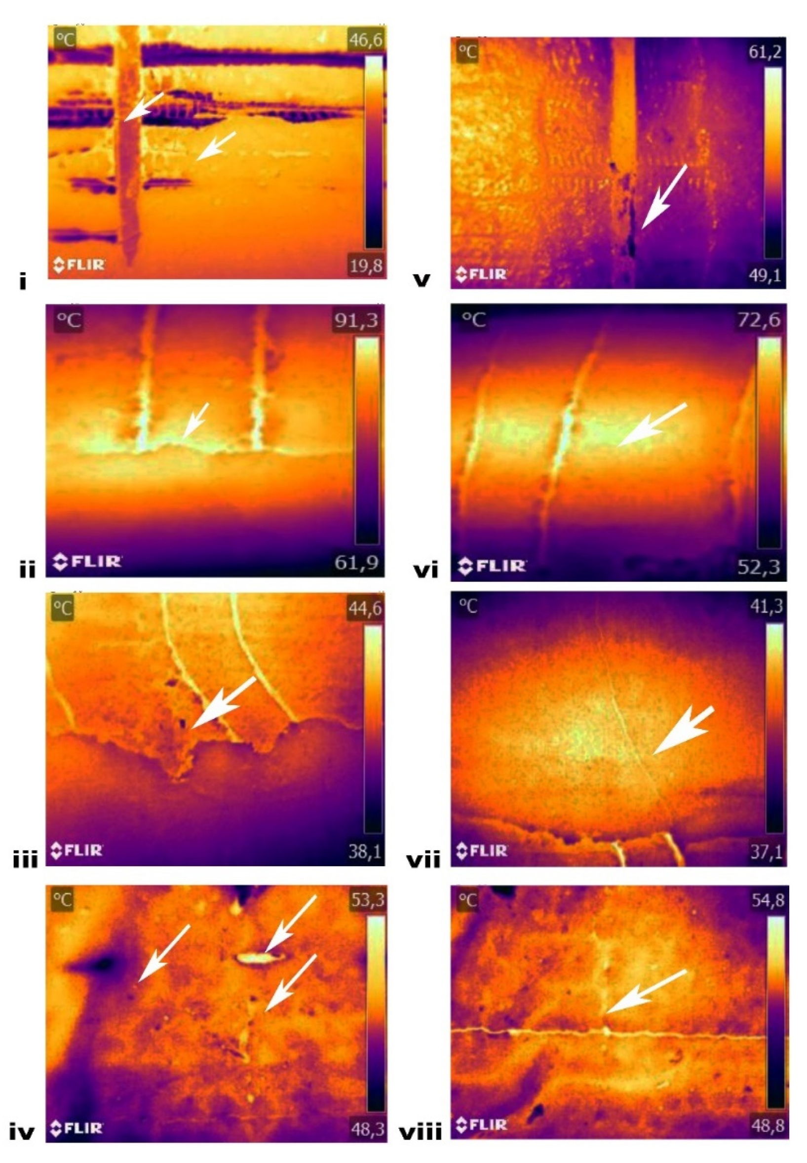
3.5. Infrared Thermography Examination

Passive infrared thermography on the frontal and backside surface of the three artworks offered inconclusive results but with active thermography the collected images were very distinctives.
Active thermographic images of the back of the artwork revealed a similar internal reinforcement system with two vertical metal bars and lateral meshes attached with metal wires. The metal parts have a lower temperature than the cement support and appear darker on the thermograph (Figure 7(i,v)). Additionally, cracks and corrosion marks are detected on the metal bars presenting a maximum thermal contrast (Figure 7(i,v)).
Areas of delamination or voids are detected, especially on K1 and K2 artworks, located mainly between plaster layer and cement mortar support (Figure 7(ii,iii,iv)). Defective and defect-free areas differ in thermal conductivity which appears higher in the delaminated region. Delamination and internal voids are few of the most common defects for cement-based materials [52,53]. This may lead to the loss of mechanical properties and can cause the failure of the overall composite material. Structural cracks, non-evident under visual inspection, can be detected on the active thermographs (Figure 7(vii,viii)). The cracks act as a thermal barrier where the absorption of IR irradiation is higher during the process and it is manifested as an area with higher temperature during cooling [54].
Thermographic images of the artworks give an overall information about their condition. In particular, K1 and K2 artworks present several structural cracks and inner cavities, localized on the areas where plaster layer superposes concrete mortar. In addition, the thermographic images of the three works of art show cavities and discontinuities, particularly around the corrosion points of the metal frame and the mesh.
When the corrosion of embedded metallic parts begins, the resulting oxides have a significantly larger volume (2 to 6 fold) than the metal itself [55,56]. As a result, these products accumulate around the rebar. The increase in volume causes internal stresses that can surpass the tensile strength of cement mortar. This phenomenon leads to the formation of micro and macro-cracks as well as delamination of the composite material, ultimately weakening the overall strength of the support system. It is crucial to monitor these areas, particularly during transport and exposure of artworks, as they pose potential risks. Despite being made from similar materials such as cement-based materials, metallic bars and mesh, and photosensitized emulsion, there are significant differences in their overall condition. K1 and K2 artworks display more severe structural cracks, microcracks, and voids compared to K3 artwork, which greatly impacts the stability of their support structures.
The reason for this variation is the diversity in the construction support used for the three artworks [57]. K1 and K2 utilize a support structure comprising cement mortar and multiple layers of cement-based plaster, overlapped to provide thickness. On the other hand, K3’s support consists of a single layer of mortar composed of different materials such as grey and white cement that are placed side by side.

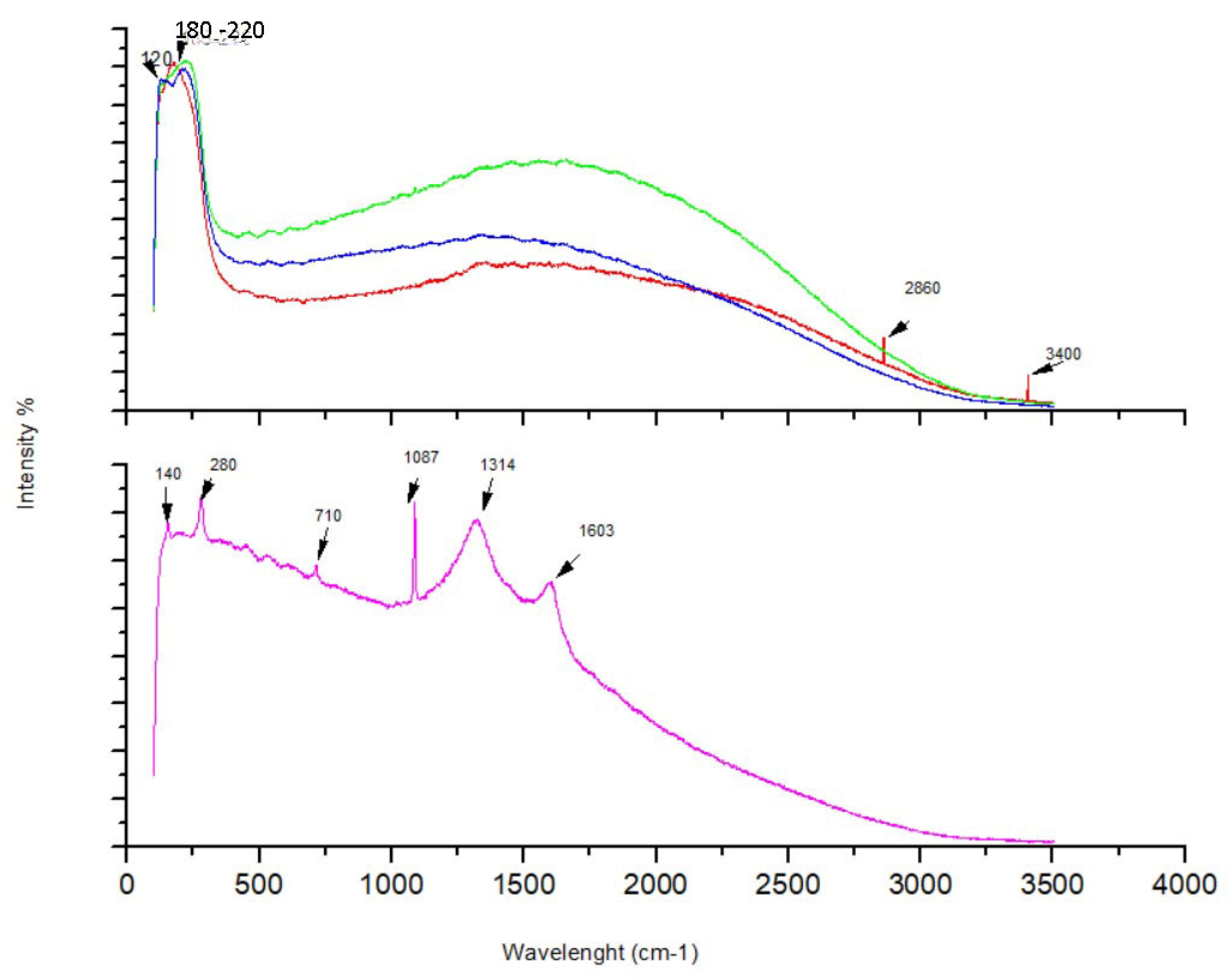
3.6. SEM-EDX and Micro-Raman

The surface of the collected samples of the three artworks, which are on cement mortar or plaster and are in different shades (white, black, grey, and yellow-brown), has a heterogeneous appearance. EDX measurement show, that the elemental compositions in the black area consist of Ag, Cl, Ca, and O. In alternative printing techniques, such as those used for these artworks, silver-based light-sensitive emulsions are commonly used. Some examples of commercial liquid photographic printing emulsions are Rockland’s Liquid Light, AG-Plus, Cachet’s Black Magic, and Silver Print Emulsion. The presence of chlorin (Cl) indicates that a silver chloride-based emulsion was used in all three artworks. This aligns with references stating that the artist utilized the commercially available Liquid Light© emulsion for his cement creations [58].
In addition to the elemental compositions mentioned earlier, the measurement in areas with brown and yellow color variation also indicates the presence of iron (Fe) and sulfur (S). The detection of sulfur, along with silver, may be attributed to the presence of silver sulfide compounds (Ag2S), which is a decomposition product of the photographic image during development and gives it a distinct yellow-brown color. Moreover, the presence of iron (Fe) can be attributed to either the composition of the cement-based mortar or the corrosion products from the metal structure used as embedded reinforcement in the support layer.
In order to characterize further the materials composing the artworks, micro-Raman spectroscopy is used. The samples are investigated in both sides (recto/photosensitive emulsion up and verso/photosensitive emulsion down). The spectra collected from the samples in areas with black and grey tones on the recto side, presents common bands in the range of 120–220 cm−1 and specifically a peak at 180–200 and a shoulder at 120–150 cm−1 (Figure 8). These bands are related to the presence of silver compounds that can be found in excess in the darkest areas. The band at 140 cm−1 could be attributed to Ag lattice vibrational modes observed in the spectra of various silver salts, whereas a Raman shift at 220 cm−1 could be assigned to AgCl stretching modes [59].
The spectra collected from the samples in areas with white tones, present a peak at 1350 cm−1 that is associated to the CH3, CH2 deforming modes and a peak at 1450 cm−1 that is associated to twisting scattering vibrations of CH3, CH2 related to the presence of Amide II that characterizes the gelatin [60].
Furthermore, the spectrum of the sample collected in the black area at K2 artwork with the retouching material, gives very distinctive peak at 1603 cm−1 followed by a peak at 1314 cm−1 (Figure 8). These peaks can be related to carbon-based black pigments and in particular black chalk (black earth) with two characteristic broad bands at 1600 and 1316 cm−1. Additionally, the presence of a narrow band at 1087 cm−1 and a band at 140 cm−1 indicates the detection of mineral impurities of calcite (1088 cm−1) and anatase (145 cm−1) [61].

4. Conclusions

The research conducted on composite artworks created using photosensitized cement and the integration of NDT methods (VIS/UVF, optical microscopy, colorimetry and IR thermography) on site yielded several important findings regarding the documentation of their composing materials, the artist’s technique and the evaluation of their overall preservation status.
Optical examination revealed various techniques used in the application of the photosensitized emulsion—either through broad brushstrokes and cross-hatching or the use of unconventional materials such as bubble wrap to create patterns on the painting’s surface. Microscopic examination revealed that excessive application of the emulsion on rough surfaces, such as cement mortar, results in the formation of clustered blisters, air cavities, superficial cracks, and microcracks. Furthermore, it was shown that the surface cracks and microcracks are related to the surface texture (smoother of rougher) and the color of the printed image (white, black, grey and brown tones). The UVF images displayed various areas that exhibit defects and deterioration in the photographic emulsion, as well as areas where the artist has applied new materials (retouched areas).
Furthermore, active IR thermography revealed that all three artworks have a common inner structure consisting of reinforced metal and a mesh enclosed by a frame. The thermographic images showed structural cracks, which are more pronounced in the artworks with a thicker layer of support and in multi-layered areas. Also, voids and areas with irregularities are detected between cement mortar and plaster surfaces. These structural cracks have resulted from the oxidation of the inner metal structure, which occurs when it is not adequately protected by cement mortar. Voids between the cement mortar and the plaster surface are the result of inadequate or negligent application and/or preparation of these layers by the artist.
Lastly, the color measurements indicate that the differences in hue, saturation, and luminosity in each of the examined artworks can be attributed to the environmental conditions in which they have been exposed over the years.
The integration of NDT results with those obtained through the examination of samples using SEM-EDX and micro-Raman analysis has proven effective in providing a comprehensive characterization of the materials employed in the creation of the artworks. These materials include plaster and cement mortar, as well as a photographic emulsion composed of silver chloride. Notably, no evidence of a coating beneath the photographic emulsion has been detected.
The utilization of NDT in this examination proved to be immensely valuable for assessing these contemporary composite artworks. This procedure can serve as a benchmark for similar cases, with the analogous technique (alternative printing) in various other supports (canvas, carton, stone, ceramic, etc.) providing important insights. The information obtained can then be used efficiently to formulate a comprehensive strategy for the restoration and preventive conservation of contemporary artworks of this type made of composite materials to ensure their long-term preservation.

Author Contributions

Conceptualization, E.S., M.K. and A.B.; methodology, E.S., M.K. and A.B.; validation, E.S., M.K. and A.B.; formal analysis, E.S.; investigation, E.S.; data curation, E.S.; writing—original draft preparation, E.S.; writing—review and editing, A.B. and M.K.; supervision, A.B. All authors have read and agreed to the published version of the manuscript.

Funding

This research received no external funding.

Institutional Review Board Statement

Not applicable.

Informed Consent Statement

Not applicable.

Data Availability Statement

Data are contained within the article.

Conflicts of Interest

The authors declare no conflict of interest.

References

  1. Adriaens, A. Non-destructive analysis and testing of museum objects: An overview of 5 years of research within COST Action G8. In Proceedings of the International Symposium on Cultural Heritage Conservation: Non-Destructive Testing Technology Application, Jerusalem, Israel, 25–30 May 2008; p. 24. [Google Scholar]
  2. Ferretti, M. Scientific Investigation of Works of Art; ICCROM: Rome, Italy, 1993; p. 92. [Google Scholar]
  3. Gavrilov, D.; Maev, R.G.; Almond, D.P. A review of imaging methods in analysis of works of art: Thermographic imaging methods in art analysis. Can. J. Phys. 2013, 92, 341–364. [Google Scholar] [CrossRef]
  4. Maev, R.; Gavrilov, D. Thermography in Analysis of Works of Art: Choice of the Optimal Approach. In Proceedings of the 3th International Symposium on Nondestructive Characterization of Materials, (NDCM-XIII), Le Mans, France, 20–24 May 2013; Curran Associates, Inc.: Red Hook, NY, USA, 2013; p. 409. [Google Scholar]
  5. Brunetti, B.; Miliani, C.; Rosi, F.; Doherty, B. Non-Invasive Investigations of Paintings by Portable Instrumentation: The MOLAB Experience; Topics in Current Chemistry Collections; Springer: Cham, Switzerland, 2016; p. 10. [Google Scholar] [CrossRef]
  6. Seymour, K. Standard non-destructive techniques used to document and examine artworks employed within the conservation field. In Proceedings of the International Symposium on Cultural Heritage Conservation: Non-Destructive Testing Technology Application, Taiwan, China, 6–7 December 2010; p. 24. [Google Scholar]
  7. Stratis, J.; Lazidou, D.; Gomez-Sanchez, E. Enhancing the examination workflow for Byzantine icons: Implementation of information technology tools in a traditional context. J. Cult. Herit. 2014, 15, 85–91. [Google Scholar] [CrossRef]
  8. Carrero, J.A.; Fernandez, L.A.; Gomez, L.; Gomez, N. Non-Destructive and Microanalytical Techniques. In Proceedings of the TECHNART, Bilbao, Spain, 2–6 May 2017; p. 440. [Google Scholar]
  9. Ranjeetkumar, G.; Daniel, M.; Jamie, B.; Harper, S.; Wenshuo, T.; Pancholi, K.; Baines, L.; Bucknall, D.G.; Flynn, D. A Review of Sensing Technologies for Non-Destructive Evaluation of Structural Composite Materials. J. Compos. Sci. 2021, 5, 319. [Google Scholar] [CrossRef]
  10. Ricca, M.; Alberghina, M.F.; Randazzo, L.; Schiavone, S.; Donato, A.; Albanese, M.P.; La Russa, M.F. A Combined Non-Destructive and Micro-Destructive Approach to Solving the Forensic Problems in the Field of Cultural Heritage: Two Case Studies. Appl. Sci. 2021, 11, 6951. [Google Scholar] [CrossRef]
  11. Bas, G.; Haase, G.; Zorgiebel, F. Some SEM Studies on Photographic Emulsions. Scanning 1983, 5, 84–90. [Google Scholar]
  12. Restany, P. La Mec-art: Una pitura meccanica alla ricerca d’una iconografia moderna. Essere 1968, 4, 14. [Google Scholar]
  13. Tsigou, E.; Kessanlis, N. The return of the Barbarian. Art Mag. 1995, 19, 40–46. [Google Scholar]
  14. Tzirtzilakis, Y. (Ed.) Nikos Kessanlis. Macedonian Museum of Modern Art; Adam: Thessaloniki, Greece, 1997; p. 228. [Google Scholar]
  15. Ross, D. The Handmade Silver Gelatin Emulsion Print; Routledge: New York, NY, USA, 2019; p. 303. [Google Scholar]
  16. Tackett, K. Alternative Photography. Printing in Objects. Available online: www.instructables.com (accessed on 15 June 2022).
  17. James, C. The Book of the Alternative Photographic Process; Delmar: Lachine, QC, Canada, 2012; p. 640. [Google Scholar]
  18. Wall, E.J. Photographic Emulsions; American Photographic Publishing Company: Boston, MA, USA, 1929; p. 280. [Google Scholar]
  19. Reed, M.; Jones, S. Silver Gelatin: A User’s Guide to Liquid Photographic Emulsions; Argentum: London, UK, 2001; p. 144. [Google Scholar]
  20. Zelikman, V.L.; Levi, S.M. Making and Coating Photographic Emulsions; Focal Press: London, UK, 1965; p. 312. [Google Scholar]
  21. Rockland Colloid LLC. Rockland Photographic Emulsions, Liquid Light and Ag-Plus Instructions. Available online: www.rockaloid.com (accessed on 28 September 2023).
  22. Arapinis, P. Reformations, Photosensitized Cement; AD Gallery: Athens, Greece, 1996; p. 4. [Google Scholar]
  23. Stamatopoulou, E.; Karoglou, M.; Bakolas, A. Contemporary artworks created on photosensitized cements: Materials and conservation state of Nikos Kessanlis “Wall-Erotica”. J. Cult. Herit. 2019, 41, 43–50. [Google Scholar] [CrossRef]
  24. Dyer, J.; Sotiropoulou, S. A technical step forward in the integration of visible-induced luminescence imaging methods for the study of ancient polychromy. Her. Sci. 2017, 5, 24. [Google Scholar] [CrossRef]
  25. Bracci, S.; Iannaccone, R.; Magrini, D. The Application of Multi-Band Imaging Integrated with Non-Invasive Spot Analyses 516 for the Examination of Archaeological Stone Artefacts. In UV-Vis LUMINESCENCE Imaging Techniques. 360 Conservation; Picollo, M., Stols-Witlox, M., Fuster-López, L., Eds.; Universitat Polytechnica de Valencia: Valencia, Spain, 2019; p. 151. [Google Scholar]
  26. Dyer, J.; Verri, G.; Cupitt, J. Multispectral Imaging in Reflectance and Photo-Induced Luminescence Modes: A User Manual; The British Museum: London, UK, 2013; p. 184. [Google Scholar]
  27. EN15886; Conservation of Cultural Property-Test Methods-Colour Measurement of Surfaces. European Committee for Standardization: Brussels, Belgium, 2010.
  28. Jonston-Feller, R. Color Science in Examination of Museum Objects; The Getty Conservation Institute: Los Angeles, CA, USA, 2001; p. 386. [Google Scholar]
  29. ISO 11664-4:2008(E)/CIE S 014-4 E:2007; Joint ISO/CIE Standard: CIE Colorimetry—Part 4: 1976 L*a*b* Colour Space. International Organization for Standardization, Vernier: Geneva, Switzerland, 2007.
  30. Nasau, K. (Ed.) Color for Science, Art and Technology; Elsevier: Amsterdam, The Netherlands, 1988; p. 511. [Google Scholar]
  31. Mitchell, D. Big Differences in UV Tubes, in UV Waves; Newsletter of the Fluorescent; Mineral Society, Inc.: Sacramento, CA, USA, 1996. [Google Scholar]
  32. Buzit Tragni, C. The Use of Ultraviolet Induced Visible Fluorescence for Examination of Photographs; Andrew, W., Ed.; Mellon Advanced Residency Program in Photograph Conservation; Georges Eastman House & Image Permanence Institute: Rochester, NY, USA, 2005; p. 36. [Google Scholar]
  33. Messier, P.; Bass, V.; Tafilowski, D.; Varga, L. Optical brightening agents in photographic paper. J. Am. Inst. Conserv. 2005, 44, 1–12. [Google Scholar] [CrossRef]
  34. Garden, M. Use of Ultraviolet Light as an Aid to Pigment Identification. APT Bull. J. Preserv. Technol. 1991, 23, 26–37. [Google Scholar]
  35. Measday, D. A Summary of Ultra-Violet Fluorescent Materials Relevant to Conservation. 2021. Available online: https://aiccm.org.au (accessed on 15 March 2021).
  36. Grys, S. Determining the dimension of subsurface defects by active infrared thermography-experimental research. Copernicus Publications/AMA Association for Sensor Technology. J. Sens. Sens. Syst. 2018, 7, 153–160. [Google Scholar] [CrossRef]
  37. Boullenois, E. Why Does Concrete Crack? Part 1—The Main Reasons. 2019. Available online: https://blog.master-builders-solutions.com (accessed on 21 March 2019).
  38. Portland Cement Association. Types and Causes of Concrete Deterioration. 2002. Available online: https://www.cement.org/ (accessed on 15 January 2019).
  39. Léang, M.; Giorgiutti, F.D.; Lay-Theng, L.; Pauchard, L. Crack opening: From colloidal systems to painting. Soft Matter 2017, 13, 5802–5808. [Google Scholar] [CrossRef] [PubMed]
  40. Chalhoun, J.M.; Leister, D.A. Effect of Gelatin Layers on the Dimensional Stability of Photographic Film. Photogr. Sci. Eng. 1959, 3, 8–17. [Google Scholar]
  41. Weaver, G. A Guide to Fiber-Base Gelatin Silver Print Condition and Deterioration; George Eastman House, International Museum of Photography and Film Image Permanence Institute, Rochester Institute of Technology: Rochester, NY, USA, 2008; p. 41. [Google Scholar]
  42. Rizzieri, R.; Mahadevan, A.; Vaziri, A.; Donald, A. Superficial Wrinkles in Stretched, Drying Gelatin Films. Langmuir 2006, 22, 3622–3626. [Google Scholar] [CrossRef]
  43. Bernier, B. Issues in Humidification and Drying of Gelatin Silver Prints. Top. Photogr. Preserv. 2005, 11, 6–16. [Google Scholar]
  44. Kejser, U.B.; Koch, M.S. Degradation of Gelatin in Historical Photographs. Imaging Sci. J. 1997, 45, 260–262. [Google Scholar] [CrossRef]
  45. Mowrey, R. Photographic Emulsion Making, Coating and Testing. The Handmade Silver Gelatin Emulsion Print; Photographic Systems, LLC: Rochester, NY, USA, 2011; p. 179. [Google Scholar]
  46. Sanderson, K. Measuring Color Change in Photographs; AIC & ICOM-CC Photographs Conservation: Wellinghton, New Zealand, 2013; p. 178. Available online: https://hclwizard.org/hclcolorpicker (accessed on 13 May 2021).
  47. Wilhelm, H. Monitoring the fading and staining of color photographic prints. J. Am. Inst. Conserv. 1981, 21, 49–64. [Google Scholar] [CrossRef]
  48. Ware, M. Mechanisms of Image Deterioration in Early Photographs, Science Museum and National Museum of Photography; Vols. Appendix III, The Colors of Silver Images; Film & Television: London, UK, 1994; pp. 71–76. [Google Scholar]
  49. Pope, C.I. Formation of Silver Sulfide in the Photographic Image during Fixation; National Bureau of Standards: Washington, DC, USA, 1960; pp. 65–73. [Google Scholar]
  50. Graedel, J.P.; Franey, G.J.; Gualtieri, G.W.; Kammlott, D.L. On the mechanism of silver and copper sulfidation by atmospheric H2S and OCS. Corr. Sci. 1985, 25, 1163–1180. [Google Scholar] [CrossRef]
  51. Bagavathiappan, S.; Lahirr, B.; Saravanan, T.; Philip, J.; Jayakumar, T. Infrared thermography for condition monitoring—A review. Infrared Phys. Technol. 2013, 63, 35–55. [Google Scholar] [CrossRef]
  52. Ammirato, F.; Zayicek, P. Infrared Thermography Field Application Guide; Tech. Rep. TR-107142; Electric Power Research Institute, Inc.: Palo Alto, CA, USA, 1999. [Google Scholar]
  53. Chrysafi, A.P.; Athanasopoulos, N.; Siakavellas, N.J. Damage detection on composite materials with active thermography. Int. J. Therm. Sci. 2017, 116, 247–253. [Google Scholar] [CrossRef]
  54. Milovanovic, B.; Pecur, I.B. Review of Active IR Thermography for Detection and Characterization of Defects in Reinforeced Concrete. J. Imaging 2016, 2, 11. [Google Scholar] [CrossRef]
  55. Suda, K.; Misra, S.; Motobashi, K. Corrosion products of reinforcing bars embedded in concrete. Corr. Sci. 1995, 35, 1651–1656. [Google Scholar] [CrossRef]
  56. Bertolini, L.; Carsana, M.; Gastaldi, M.; Lollini, F.; Redaelli, E. Corrosion of Steel in Concrete: Prevention, Diagnosis, Repair; John Wiley & Sons: Hoboken, NJ, USA, 2013; p. 434. [Google Scholar]
  57. Szelag, M. Evaluation of cracking patterns in cement composite-From basics to advances: A review. Materials 2020, 27, 2490. [Google Scholar] [CrossRef]
  58. Karambinis, L.; Tsironis, A. Conservation Problems of Mixte Media Paintings, Nikos Kessanlis, 1957–1989. Master’s Thesis, Technological and Educational Institute of Athens, Athens, Greece, 1996. [Google Scholar]
  59. Marucci, G.; Monno, A.; van der Werf, D. Non invasive micro-Raman spectroscopy for investigation of historical silver salt gelatin photographs. Microchem. J. 2014, 117, 220–224. [Google Scholar] [CrossRef]
  60. Fruschour, B.G.; Koenig, J.L. Raman Scattering of Collagen, Gelatin, and Elastin. Biopolymers 1975, 14, 379–391. [Google Scholar] [CrossRef]
  61. Coccato, A.; Jehlicka, J.; Moens, L.; Vandenabeele, P. Raman spectroscopy for the investigation of carbon-based black pigments. J. Raman Spectrosc. 2015, 46, 1003–1015. [Google Scholar] [CrossRef]
Figure 1. Macro-digital photography of the front side (a) and back side (b) of the three artworks (K1K3).
Heritage 06 00381 g001
Figure 2. (ac). Documentation of the artist craftsmanship (brush imprints) using macro-photography at K1 (a), K2 (b) and K3 (c) artworks.
Heritage 06 00381 g002
Figure 3. Backside surface detail using macro-photography showing the corroded metallic structure for K1 (a), K2 (b) and K3 (c) artworks and signs of the same corrosion at the frontal surface for K1 (d), K2 (e), K3 (f).
Heritage 06 00381 g003
Figure 4. Fluorescence of the artworks under UV-A (K1aK3a) and UV-C (K1bK3b) radiation.
Heritage 06 00381 g004
Figure 5. Examination of the photosensitized surface with the portable optical microscope under various magnifications (K1 cement mortar (i,v,ix) and K2 plaster (ii,vi,x) ×30), (K2 cement mortar (iii,vii), K2 plaster (iv,viii) ×30) and (K3 cement mortar (xi) ×30 and K3 plaster (xii) ×120).
Heritage 06 00381 g005
Figure 6. H*C*L* measured values of white (a), black (b) and grey (c) tones on the three artworks (K1: red circle, K2: yellow circle and K3: blue circle).
Heritage 06 00381 g006
Figure 7. (iviii): Active thermographic images at the frontal examination of K1 (i,v,vi), K2 (ii,iii,vii) and K3 (iv,viii) artworks.
Heritage 06 00381 g007
Figure 8. Raman spectra of areas with black color on cement mortar and plaster support and (Red line for K1, Blue line for K2 and Green line for K3), spectra of the area with the retouching (Purple line).
Heritage 06 00381 g008
Table 1. Color measurements on white, black and grey tones areas to K1, K2 and K3 artworks.
WhiteBlackGrey
Κ1K2K3K1K2K3K1K2K3
Lmean66.4 ± 2.1671.5 ± 2.9571.8 ± 3.9131.9 ± 2.3436.5 ± 5.848.1 ± 4.2254.7 ± 6.3753.9 ± 4.3753.4 ± 1.97
a* mean0.58 ± 0.370.21 ± 0.130.81 ± 0.5−0.20 ± 0.18−0.35 ± 0.360.20 ± 0.311.31 ± 0.38−0.18 ± 0.213.01 ± 0.15
b* mean7.36 ± 0.738.79 ± 0.729.30 ± 0.870.76 ± 1.711.99 ± −1.875.48 ± 1.435.98 ± 2.515.56 ± 1.265.92 ± 0.65
C* mean7.43 ± 0.828.80 ± 0.729.34 ± 0.981.23 ± 1.491.69 ± −0.855.34 ± 1.396.20 ± 2.435.58 ± 1.265.93 ± 0.64
H* mean82.9 ± 8.9782.7 ± 0.6566.0 ± 2.41−12.9 ± 56.53−52.2 ± 5042.1 ± 20.4172.3 ± 15.851.1 ± 8.7174.1 ± 13.89
Table 2. Color measurements of areas with yellow-brown tones on K1 and K2 artworks.
BrownYellow-Brown
K1K2K2
Lmean33.57 ± 3.1841.21 ± 5.6668.25 ± 4.88
a* mean2.35 ± 2.21−0.12 ± 0.73−0.05 ± 0.36
b* mean7.04 ± 3.073.75 ± 2.356.34 ± 1.15
C* mean7.47 ± 3.173.42 ± 6.0511.41 ± 2.59
Hue57.66 ± 37.79−36.52 ± 72.24−59.27 ± 45.99
Color values (L*, a*, b*) of white tones measured on the three artworks show a lower value of L* for K1 (66.41), whereas the other two values (a* and b*) present non-significant differences amongst the artworks examined. Comparison of color (C*) and saturation (H*) values of the white tones, highlight the lower saturation of K3 (Figure 6a).
Disclaimer/Publisher’s Note: The statements, opinions and data contained in all publications are solely those of the individual author(s) and contributor(s) and not of MDPI and/or the editor(s). MDPI and/or the editor(s) disclaim responsibility for any injury to people or property resulting from any ideas, methods, instructions or products referred to in the content.

