Article

X-CT Reconstruction as a Tool for Monitoring the Conservation State and Decay Processes of Works of Art and in Support of Restoration and Conservation Strategies

1
Dipartimento di Fisica, Università di Torino & INFN—Sezione di Torino, Via Pietro Giuria 1, 10125 Torino, Italy
2
Centro per la Conservazione ed il Restauro dei Beni Culturali “La Venaria Reale”, Via XX Settembre 18, Venaria Reale, 10078 Torino, Italy
3
Research Institute for the Dynamics of Civilizations, Okayama University, 3-1-1 Tsushima-naka, Kita-ku, Okayama 700-8530, Japan
*
Authors to whom correspondence should be addressed.
Heritage 2025, 8(2), 52; https://doi.org/10.3390/heritage8020052
Submission received: 3 December 2024 / Revised: 20 January 2025 / Accepted: 21 January 2025 / Published: 27 January 2025

Abstract

:
X-ray Computed Tomography (X-CT) is now an established technique for the investigation and diagnostics of Cultural Heritage. Its advantages include non-invasiveness, non-destructiveness, and the possibility of exploring the inner parts of an object without any modification. X-CT is often employed to investigate the construction methods of complex artifacts made with different parts or materials, but it is also able to support the analysis, intervention, monitoring and enhancement processes of artworks, creating digital models that can aid in the conservation and restoration procedures. In this work, several case studies are presented in which the CT technique has been decisive in identifying the effects of time and the events that occurred during the object’s life influencing its state of conservation. These range from large objects, such as an 18th century CE writing cabinet or an ancient Egyptian wooden coffin, to very small artifacts, like Mesopotamian lapis lazuli beads or fragments of Roman colored glass. Additionally, the results obtained by µ-CT investigations on the conservation state of a bronze arrowhead uncovered from the Urama-chausuyama mounded tomb (Japan, Kofun period, end of the 3rd century CE) are presented here for the first time. Lastly, the versatility of the technique when applied with different setups is highlighted.

1. Introduction

Many transformations can occur in a work of art, starting from its creation. Physical, chemical and biological changes can affect its structure, appearance, composition and integrity as time goes on. Sometimes changes are not visible from the outside, or conversely, an apparently destroyed object might actually hide inside a pristine part. In such cases, an analysis of the inner part of the object is needed to assess its actual conservation state. X-ray Computed Tomography (X-CT) has been borrowed from the medical field since the 1980s for the investigation and diagnostics of Cultural Heritage [1]. Its advantages include non-invasiveness, non-destructiveness and the possibility of exploring the inside of an object without modifying it in any way and without inducing activation. X-CT is based, like radiography, on the different X-ray attenuation coefficients characteristic of each material in relation to their composition, density or thickness, introducing in addition a complete rotation during the acquisition of the images: in this way, it allows the creation of 3D digital models to support the analysis, intervention, monitoring and enhancement processes of artworks. Moreover, the analysis can be repeated endless times at different stages in the life cycle of the artifact in order to monitor the evolution of the conservation state and identify an eventual decay of the constitutive material or of the structure. The possibility of performing the analysis in situ (e.g., museums) [2,3] facilitates the application of the technique even more, avoiding the displacement of the object outside its neutral environment and limiting any additional stress imposed on the materials. Conversely, large-scale X-CT can be a powerful technique for the non-destructive visual inspection of historic structures in our Cultural Heritage, such as damaged timber structural elements from an 18th century bridge [4].
In several cases, the technique is decisive in identifying the effects of time and the events that occurred during the object’s life, influencing its state of conservation. Some examples are offered from the study of wooden-based objects, where X-CT is generally employed to detect cracks or deformations undermining the health of the artifact [4,5,6]. Dimensional changes can occur instead in the case of previously waterlogged artifacts when they are removed from the original environment: for shrinkage, collapse and cracks, even if the changes are very small, an evaluation can be successfully achieved by means of CT [7]. Mineralization of wood can also happen after prolonged contact between metallic and wooden parts of the same object, and a tomographic study can assess the stage of the process and help establish strategies for preventive conservation [8].
Also, the conservation conditions and environment can influence the preservation of the artifact, and X-CT scanning can be used to monitor the occurrence of features caused by the specific characteristics of the burial soil or the environmental conditions in museums [9,10,11,12]. In this regard, CT can also be exploited to analyze and extract the original form and scope of artifacts embedded in soil blocks that are heavily damaged from the time spent under burial, supporting restoration interventions [13,14,15].
The activity of biological factors can be surveyed as well by means of CT, which can, for example, reveal xylophagous insect strikes in wooden objects [16,17]; repeating the analysis some time after an anoxic treatment can be an easy way to confirm the success of the procedure, verifying that no new holes have been formed inside the artwork. The decay processes involving relatively modern materials can also be studied, such as cement mortars [18], which are constitutive components of architecture or objects that have become part of Cultural Heritage only in recent times.
Generally, X-ray CT can have limited investigative power for metallic artifacts due to the high absorption of this kind of radiation by heavy metals (iron, copper, tin, lead and so on). However, this limitation is not an issue for small and highly degraded metallic artifacts: if anything, the high contrast resulting from the difference in composition and density between the areas is helpful to better identify any remaining metal inside the object [19,20]. A quite common application of the technique is in numismatic studies, to be able to examine the metal hidden behind the corrosion layer and in some cases to extract the marks and decorations and successfully reach a classification of the coins [21,22,23,24,25]. In general, this also means that when cleaning the object is not possible, as it would also destroy the preserved part, X-CT guarantees at least the virtual valorization of the original artifact.
The examples of tomographic investigations reported in this work show how it is possible with versatile instrumentation to go beyond the effects of time and reveal the actual state of conservation of the object, while studying the causes that led to the eventual damage. After reporting specific time-dependent effects on artifacts already studied with X-CT with different aims, the evaluation of metal corrosion in a bronze arrowhead from a Japanese mounded tomb is presented for the first time.

2. Materials and Methods

Most of the case studies presented here have been investigated in their entirety or with different purposes elsewhere, while in this work, we focus our attention on the effect of time-dependent damages or alterations on diverse materials. Specifically, the objects under investigation are (1) the “doppio corpo” writing cabinet by Pietro Piffetti [26], (2) the lid of Taiefmutmut’s wooden coffin [27], (3) a soil block retrieved from the archaeological site of Villalfonsina (Abruzzo, Italy) [28], (4) a ceramic tintinnabulum [29], (5) lapis lazuli beads from the Royal Graves of Ur (Mesopotamia) [30], (6) fragments of colored glass from the archaeological site of Aquileia (North-Eastern Italy) [31], and (7) a historical wooden transverse flute (Traversiere) [32]. We refer to the cited literature for a complete description of the objects and their historical contexts. To take into account bulk metallic artifacts, we also report for the first time on a tomographic study on the state of conservation of a bronze arrowhead on display at the Okayama University Archaeological Museum in Japan. The arrowhead (number 12) is part of a collection of around 20 samples unearthed from the Urama-chausuyama mounded tomb (Kofun period, end of the 3rd century CE), located in Okayama Prefecture. Urama-chausuyama is a keyhole-shaped mounded tomb measuring 138 m in length. While its stone burial chamber was heavily looted and most of the burial goods had been lost, the 1988 excavation retrieved fragments of a bronze mirror, bronze and iron arrowheads, and single- and double-edged iron swords, in addition to tools such as axe heads and knives, agricultural implements such as sickles and spades, and fishing gear such as harpoons [33]. In particular, arrowhead number 12 displays a peculiar pentagonal shape (Figure 1). In recent years, the arrows were coated with a layer of paraloid B72 for conservation purposes. The surface, although cohesive in appearance due to a mineralization layer [34,35,36], shows relevant signs of degradation (localized to some areas and fractures on the surface), but inspection with optical microscopy could not provide information on the health conditions of the innermost part.
Several X-CT systems have been used for data acquisition, including both custom-made setups and benchtop machines. Custom setups are placed in shielded rooms as they can occupy a large amount of space, while benchtop ones deal with radioprotection employing a smaller closed cabinet. During the analysis, the rotation is always applied to the object, while the X-ray source and the detector are kept in the same position. The characteristics of different instrumentation and the chosen parameters for each analysis are reported in Table 1. Custom-made laboratory setups are based in two different locations; both systems have been developed by the Physics Department of the University of Torino and the INFN (Italian National Institute for Nuclear Physics). The micro-CT system employed is located at the Physics Department of the University of Torino, and it is thoroughly described in [32]. It is particularly of use when the investigation requires high resolution of very small details (the nominal minimum focal spot size is 5 µm, for a minimum voxel size of about 6–10 µm). The acquisition is rather quick thanks to the use of the available flat panel detectors, exploiting different active areas. The X-CT system for large objects is instead hosted at the Center for Conservation and Restoration “La Venaria Reale” in Venaria Reale, near Torino [37]. This setup can achieve a higher X-ray energy (source maximum voltage is 200 kV), but it relies on a linear detector horizontally scanning the area of interest to perform the two-dimensional (2D) radiographs [38]. The geometry of the setup and the X-ray beam characteristics were optimized for each case, taking into account the type of the material and the dimensions of the object. The different source-detector, source-object and object-detector distances can be modified, especially in the customized setup, to act on the magnification of the image. The projections were acquired through a custom-made Labview routine that synchronizes the rotation motion and the projection acquisition. The same routine was used to acquire “open-beam” images (same conditions, no sample) and “dark” images (X-rays off), which were averaged using MATLAB software (version R2023b) by MathWorks.
The benchtop X-CT system used instead for the tomographic acquisition of the bronze arrowhead is a SHIMADZU inspeXio SMX-225CT FPD HR Micro Focus X-Ray CT System hosted at Shimadzu Techno-Research, Inc. in Kyoto, Japan. To reduce beam hardening effects during the analysis of metallic objects, a 200 kV tube voltage was set, and a 1 mm thick copper filter was used instead of an aluminum filter. The instrument is equipped with a microfocus X-ray source for high-resolution analysis and a flat panel to make the acquisitions faster (only 20 min for each acquisition). Taking also into account the geometric conditions given in Table 1, the voxel size obtained was 45 µm.

3. Results and Discussion

In this section, we present the results obtained from the tomographic observations related to the effects of time, grouping, in particular, the observed features affecting the integrity of the objects by means of different agents.

3.1. Breaking from Prolonged Use
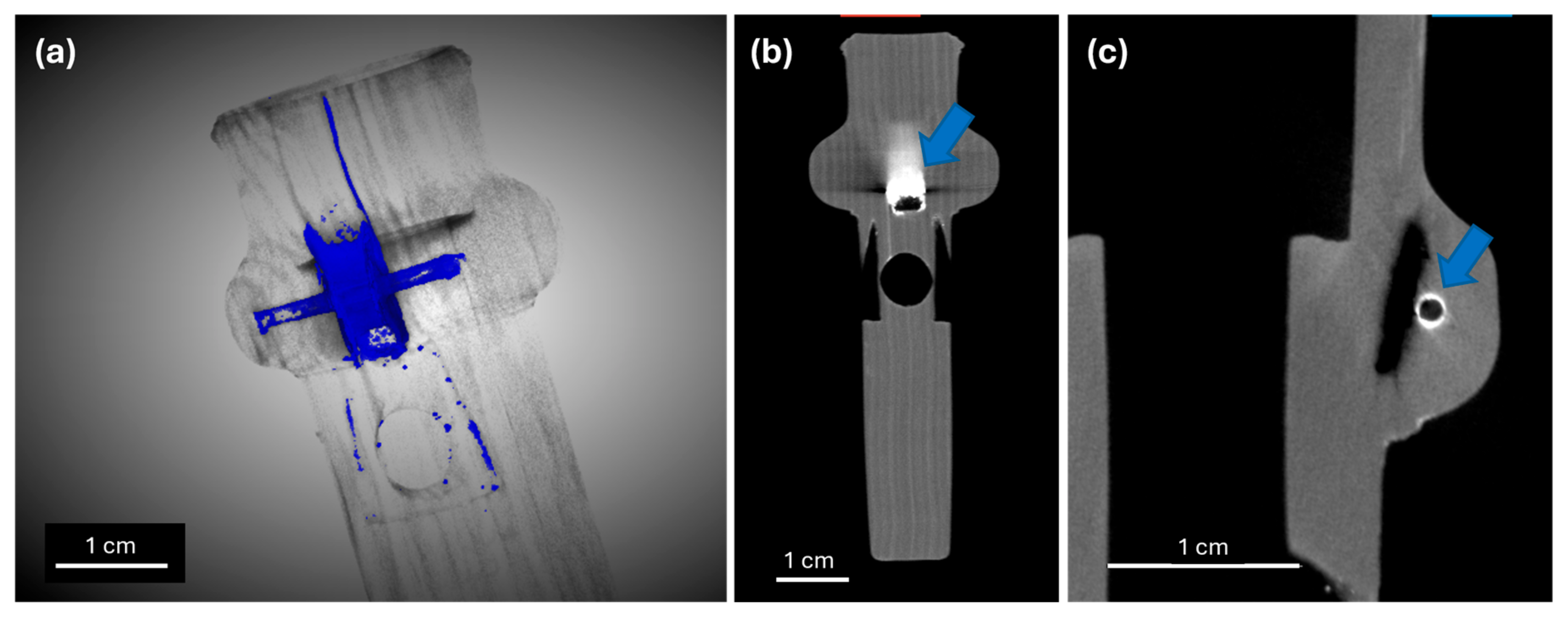
A ceramic rattle (“tintinnabulum”) from Cyprus (dated by comparative analysis back to the Iron or Roman age, 600 BCE-150 CE), modeled in the shape of a boar, has been studied with X-CT to better understand the mechanism producing the sound. The analysis actually revealed that the repeated shaking of the object had induced the formation of cracks in the ceramic material. From CT slices and a three-dimensional (3D) model, cracks are visible in the ceramic body and, even more importantly, the complete fragmentation of one of the three rattling spheres is revealed (see Figure 2). Moreover, inside one of the remaining rattling spheres a new incomplete crack is visible, suggesting that any future shaking (even only for demonstrative purposes) is to be avoided, in order to prevent further destruction.

3.2. Ion Migration

A different example is provided by a wooden-based multi-material object: a boxwood transverse flute (“Traversiere”) by Lorenzo Cerino (late 18th century CE). This flute is made up of four separate pieces, and in the foot, a brass key is installed. The key was removed for the X-CT analysis, because the original scope of the investigation was to establish the conservation state (e.g., the presence of cracks) and the exact dimensions of the pieces for a metrologically accurate 3D printed replica; moreover, the metallic key might have induced artifacts in the images. Studying the foot, however, it was found that, in time, ion migration occurs inside the wood from the brass key at the installation spot: metallic residues are, in fact, visible and quite easily distinguishable in the X-CT slices as more radiopaque (brighter) areas (Figure 3).

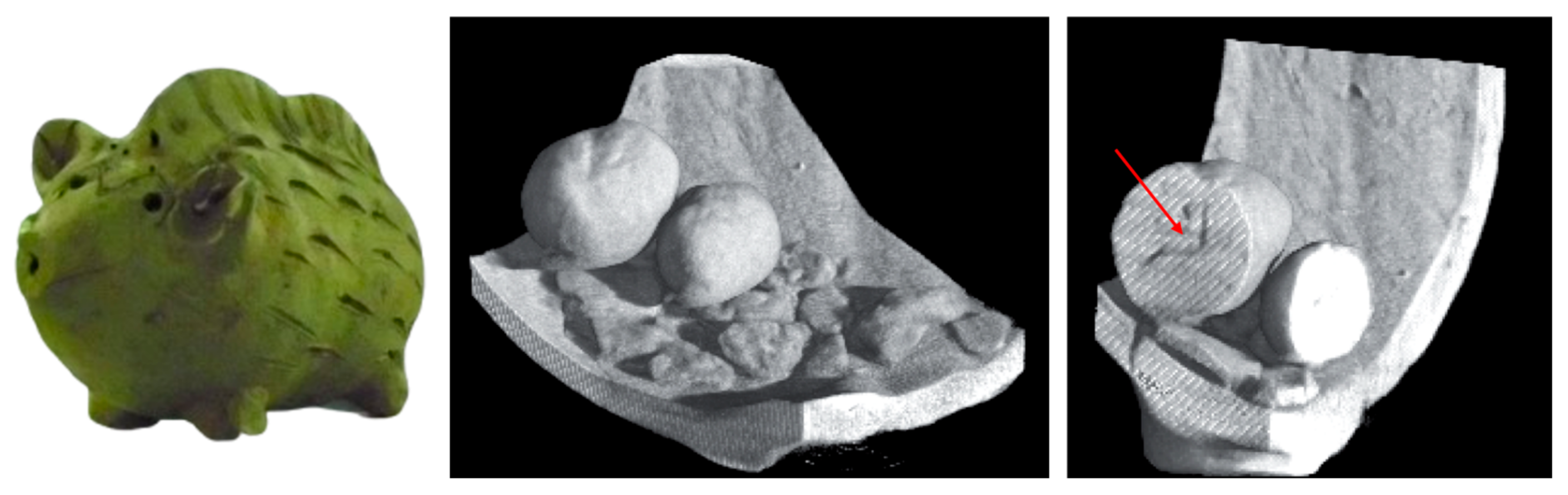
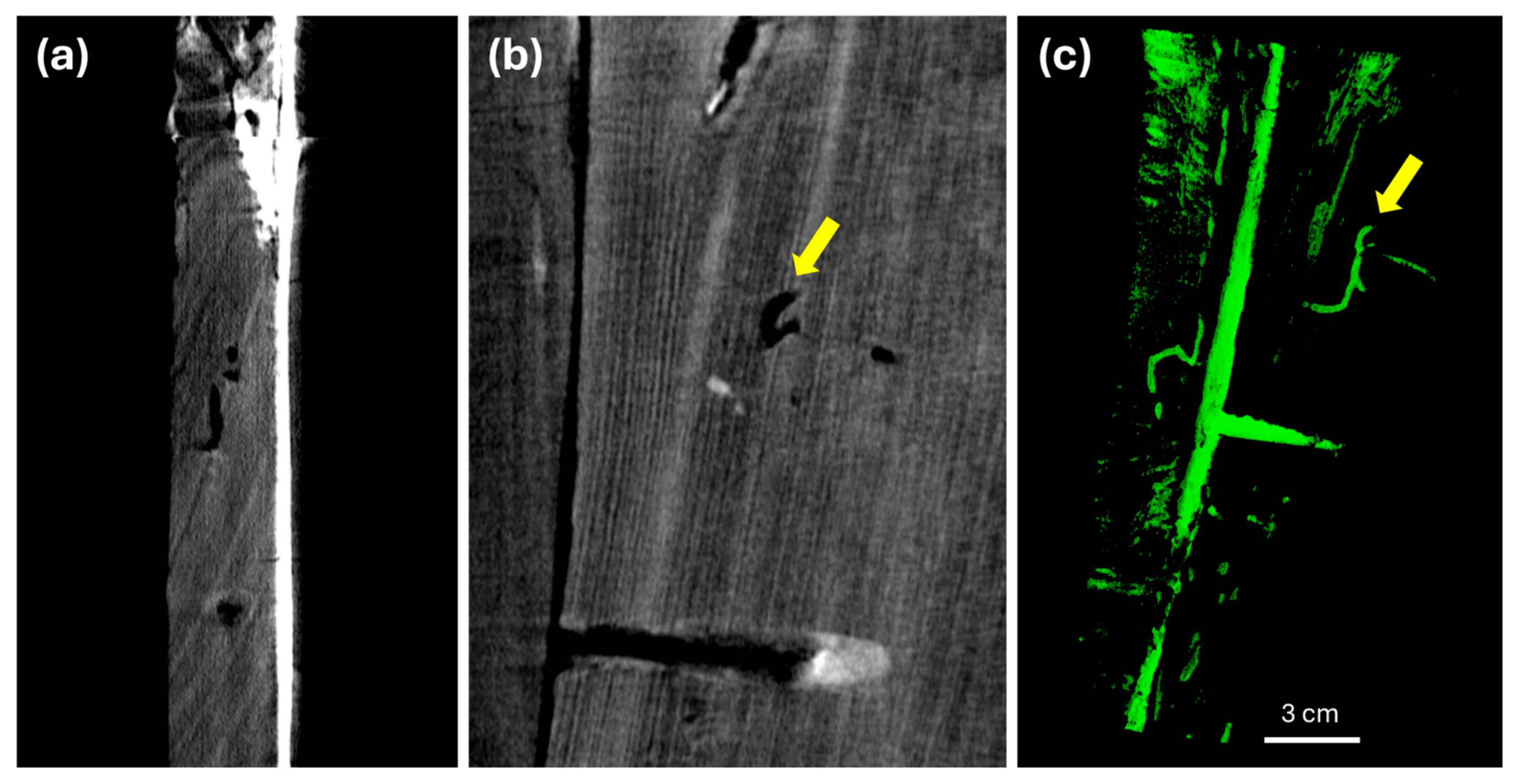
3.3. Biological Activity

The presence of xylophagous insects inside ancient wooden material is the cause of the formation of diffused holes: these can be seen sometimes from the outside on the artifact surfaces, while still not knowing the extent of the damage inside the whole wooden block.
From X-CT analysis, the extension of the insects’ attack can be evaluated. During the years, it was possible for us to study some large wooden artifacts; in particular, some interesting cases are the Taiefmutmut’s coffin lid (21st Dynasty, 1076–746 BCE) and the “doppio corpo” writing cabinet by Pietro Piffetti (18th century CE). In the coffin lid, despite the age of the artifact, the attack is not largely diffused but is relatively concentrated in a few areas. Performing a segmentation of the hollow parts inside the wooden material, as in Figure 4c, it is possible to visually investigate in the 3D space the distribution and shape (bending, bifurcations) of the cavities left by the insects. In Piffetti’s artwork, on the other hand, the holes are located only in some of the wooden blocks used for the construction, specifically those appearing brighter in X-CT and probably made of walnut wood. The segmentation of voids in the single block revealed, in this case, a dense network of cavities (Figure 5c). Such an extensive perforation can be dangerous for the integrity of the block, also exposing the internal part of the wood to other environmental factors such as humidity and pollutants. This kind of non-invasive investigation can be a great support for conservators’ interventions: repeating the analysis some time after an anoxic treatment can also be an easy way to confirm the success of the procedure.

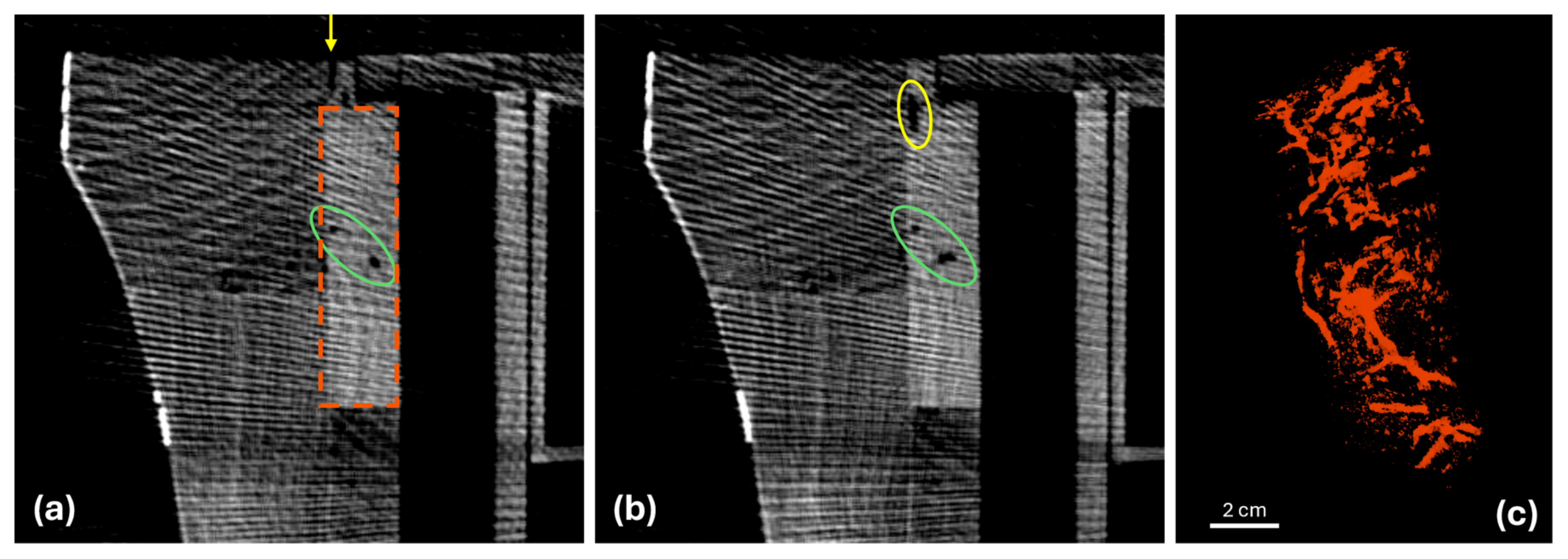
3.4. Environmental Effects

The environment hosting an artifact for years, centuries or millennia can greatly influence the conditions of the object and its integrity at retrieval. Several mechanisms can be activated in time depending on the environment composition (acidic/basic), humidity conditions, mechanical stress and so on. We have been able to study several objects and different materials, each one showing different interactions and producing different stages of damage.
The first example is a soil block extracted directly from the excavation terrain at the necropolis of Villalfonsina (Abruzzo, Italy), probably dating back to the 6th–4th centuries BCE. From the preliminary observations, the bronze artifact embedded in soil was already clearly identified as fragile and fragmented. In fact, the bronze belt contained in the block was exposed during burial both to the chemical effects of organic decomposition of the body originally wearing the ornament and to the pressure of the burial soil, causing the flaking and splintering of the metal into small fragments.
CT segmentation revealed in a non-invasive way the distribution, shape and dimensions of fragments, isolating them from the earthy material (as shown in Figure 6), as well as indications about the belt’s general conditions, the identification of repairs done in the past and the presence of different materials. This information supported the belt restoration in accounting for the documentation of all the fragments to be extracted and cleaned and their original position for solving the puzzle. The belt was finally reassembled and protected using resins and waxes.
Another example is provided by archaeological glass kept in the ground until the present day. The glass fragments presented here were discovered on the plow soil surface around the ancient Roman city of Aquileia (North-Eastern Italy) and are part of a larger set identified to thoroughly study the different types of corrosion that can occur on the vitreous material after the long interaction with soil. These two fragments in particular are characterized by the formation of a crack network (n. 581755) and the presence of a superficial iridescent patina (n. 581681). µ-X-CT analysis allowed the determination of the size of cracks and pits and their extension inside the glass, as well as the morphology of the patina and its stratification.
The cracks in sample 581755 feature rounded ends, suggesting the possible influence of soil mechanics in fracturing the glass through erosion. From reconstruction and segmentation, it was possible to visualize the dense crack network and some larger and smaller soil grains entrapped in the main hole (the sample was originally a bead; see Figure 7). The cracks extend deep into the object (even 4–5 mm) with diameters of about 100–200 µm. Inside the cracks, it is visible from CT slices the presence of a material less radiopaque than the glass bulk (Figure 7d): it was possible to estimate that more than 10% of the glass object is altered into this different material, possibly hydrated silica.
For sample 581681 it was instead possible to measure the thickness of the patina (almost 2 mm thick) and to observe that it is composed of a sequence of alteration packets and air, apparently detaching from the bulk while following the same profile. The sample also shows the presence of pits (as the one shown in Figure 8b): the high resolution of µ-CT allows us to identify in the pit an ordered structure of concentric layers. All these phenomena are in general due to cycles of dissolution and reprecipitation of the glass material, exacerbated by the presence of salts in the soil.
µ-CT resolutions are even able to discriminate features in very small artifacts, such as small carved beads. Within a study on lapis lazuli provenance, µ-CT was performed on three lapis lazuli beads from the Royal Graves of Ur (Mesopotamia, Iraq, 3rd millennium BCE). One of the issues of archaeological lapis lazuli is the frequent alteration of the pyrite crystals present inside this kind of semi-precious stone, with a higher occurrence on the surfaces. The alteration is caused by environmental conditions such as high humidity, percolating waters, or thermal stress, and it results in the loss of sulfur and in the consequent transformation of pyrite into iron oxide–hydroxide minerals. It was verified that the alterations are recognizable with µ-CT thanks to the different radiopacity, resulting from the loss of S and the remaining Fe and O as main elements. The extension of this modification is also evaluable in terms of thickness and diffusion of the alteration layers in the whole volume. It is interesting to notice that the tomographic investigation revealed the presence of some cracks in the bead (orange arrows in Figure 9), which may be the vector for humidity coming from the external environment to reach the inner pyrite crystals, inducing the alteration also in the deepest crystals.
Lastly, we present here the first insights that can be obtained from the µ-CT analysis of a bronze arrowhead unearthed from the burial chamber of the Urama-chausuyama mounded tomb (end of the 3rd century CE). As shown in Figure 10a,b, the arrowhead presents a black/dark green appearance with different hues, with a quite homogeneous surface apart from some localized material losses and cracks (see Figure 1). As reported in the literature, in high-tin bronze, as in the case under investigation, the dark patina could be formed by a mineralization process with a loss of copper and lead [34]. It could act as a kind of natural protective, as in the case of ancient mirrors [35], because it is stronger in resisting corrosion processes [36]. This is not the only possible mechanism of mineralization, but, in general, the lower density and atomic weight of the corroded material is an indicator of a degradation process of the bronze. This can be well highlighted by means of µ-CT (Figure 10c), observing the areas with lower absorption of X-rays (dark areas). In particular, we can see that the darker areas are present not only on the surface that was in contact with the soil, but also widely spread below the patina, particularly starting from the fractures and losses in the patina itself. In some areas, the corrosion crosses the arrowhead from side to side (red and yellow slices in Figure 10c). The actual state of preservation of the pristine metal can be evaluated by performing a segmentation of the most absorbing volumes (brighter in CT), presumably the healthiest parts of the arrowhead. The result is presented in Figure 10d and it shows a very different situation from what was deduced from optical observations, where the artifact appears to be in better health. Information obtained via µ-CT, in addition to providing insight into the state of preservation of the arrowhead, can also be used to consider appropriate conservation measures and to verify whether the process of degradation is still ongoing or has stopped, performing additional µ-CT analyses in the future.

4. Conclusions

The different case studies presented in this work highlight how X-CT can reveal a variety of modifications induced in the whole volumes of artifacts by their conservation history and environment. Sometimes, surprisingly, the effects can have a high relevance on the future health of the objects, and they should be taken into consideration by the restorers who are devoted to their preservation. X-CT should be more and more considered and exploited as a support in conservation plans and strategies, in order to better target the interventions and also avoid unnecessary operations that would just put more stress on the object. As shown above, X-CT setups can be versatile and the best one in terms of energy, resolution, time and costs can be selected to better adapt to the conservation questions and the object itself. Together with microclimatic and environmental studies, X-CT can be fundamental in promoting preventive conservation and protecting our Cultural Heritage from further damage while maintaining its valorization.

Author Contributions

Conceptualization, A.R. and A.L.G.; methodology, A.R. and A.L.G.; formal analysis, L.G., A.R., F.T., L.V. and C.R.; investigation, L.G., A.R., F.T., L.V., C.R., J.R. and A.L.G.; resources, J.R.; data curation, L.G., A.R., F.T., L.V. and C.R.; writing—original draft preparation, L.G., J.R. and A.L.G.; writing—review and editing, A.R., F.T., L.V. and C.R.; visualization, L.G., A.R., F.T., L.V., C.R. and A.L.G.; supervision, A.R. and A.L.G.; project administration, J.R.; funding acquisition, J.R. and A.L.G. All authors have read and agreed to the published version of the manuscript.

Funding

This research was partially funded by the RECTOR (“International Research Center Formation Program to Accelerate Okayama University Reform”) program of Okayama University, in addition to the Innovative Knowledge Hub for Humanities and Materials Science (IKH), under the project number JPMXP1323015473, through the Ministry of Education, Culture, Sports, Science and Technology (MEXT) of Japan. This research has also been partially funded within the H2020-MSCA-RISE-2018 call with the Grant Agreement no 823826, for the project BE-ARCHAEO, “BEyond ARCHAEOlogy: an advanced approach linking East to West through science, field archaeology, interactive museum experiences”. Results reported in this paper reflect only the authors view and the Agency is not responsible for any use that may be made of the information it contains. The Italian PNRR—Partenariato Esteso 5 project “CHANGES: Cultural Heritage Active Innovation for Next-Gen Sustainable Society” Spoke 6: history, conservation and restoration of Cultural Heritage is also acknowledged for financial support.

Data Availability Statement

The raw data supporting the conclusions of this article will be made available by the authors upon request.

Acknowledgments

The authors wish to acknowledge the contribution of all the people involved in the mentioned case studies previously published, who contributed with different expertise and/or provided the objects, namely: F. Albertin, C. Avataneo, R. Boano, L. Bonizzoni, M. Borla, C. Bortolin, P. Buscaglia, R. Brancaccio, L. Chiaberge, J. Corsi, G. Cotto, S. De Blasi, M. Demmelbauer, G. Dughera, E. Durisi, W. Ferrarese, G. Franceschin, A. Giovagnoli, N. Grassi, S. Grassini, C. Greco, G. Herrmann, G. Iori, R. Law, E. Longo, P. Luciani, M. Magalini, G. Mangiapane, M. Martini, P. Mereu, G. Mila, M. Nervo, N. Pastrone, F. Prino, L. Ramello, M. Ravera, G. Ricchiardi, A. Romero, R. Sacchi, A. Staiano, M. Staropoli, A. Traviglia, L. Visca, L. Zamprotta, R. Zanini. The INFN CHNet network is warmly acknowledged.

Conflicts of Interest

The authors declare no conflicts of interest. The funders had no role in the design of the study; in the collection, analyses, or interpretation of data; in the writing of the manuscript; or in the decision to publish the results.

References

  1. Hughes, S. CT Scanning in Archaeology. In Computed Tomography—Special Applications; Saba, L., Ed.; InTech: London, UK, 2011; pp. 57–70. [Google Scholar] [CrossRef]
  2. Albertin, F.; Bettuzzi, M.; Brancaccio, R.; Morigi, M.P.; Casali, F. X-Ray Computed Tomography In Situ: An Opportunity for Museums and Restoration Laboratories. Heritage 2019, 2, 2028–2038. [Google Scholar] [CrossRef]
  3. Oliveira, R.; de Paula, A.; Gonçalves, F.; Bueno, R.; Calgam, T.; Azeredo, S.; Araújo, O.; Machado, A.; Anjos, M.; Lopes, R.; et al. Development and characterization of a portable CT system for wooden sculptures analysis. Radiat. Phys. Chem. 2022, 200, 110409. [Google Scholar] [CrossRef]
  4. Björngrim, N.; Myronycheva, O.; Fjellström, P. The use of large-scale X-ray computed tomography for the evaluation of damaged structural elements from an old timber bridge. Wood Mater. Sci. Eng. 2022, 17, 1028–1029. [Google Scholar] [CrossRef]
  5. Friml, J.; Procházková, K.; Melnykc, G.; Zikmundb, T.; Kaiser, J. Investigation of Cheb relief intarsia and the study of the technological process of its production by micro computed tomography. J. Cult. Herit. 2014, 15, 609–613. [Google Scholar] [CrossRef]
  6. Vigorelli, L.; Re, A.; Buscaglia, P.; Manfredda, N.; Nervo, M.; Cavaleri, T.; Del Vesco, P.; Borla, M.; Grassini, S.; Guidorzi, L.; et al. Comparison of two ancient Egyptian Middle Kingdom statuettes from the Museo Egizio of Torino through computed tomographic measurements. J. Archaeol. Sci. Rep. 2022, 44, 103518. [Google Scholar] [CrossRef]
  7. Stelzner, J.; Stelzner, I.; Martinez-Garcia, J.; Gwerder, D.; Wittköpper, M.; Muskalla, W.; Cramer, A.; Heinz, G.; Egg, M.; Schuetz, P. Stabilisation of waterlogged archaeological wood: The application of structured-light 3D scanning and micro computed tomography for analysing dimensional changes. Herit. Sci. 2022, 10, 60. [Google Scholar] [CrossRef]
  8. Haneca, K.; Deforce, K.; Boone, M.N.; Van Loo, D.; Dierick, M.; Van Acker, J.; Van Den Bulcke, J. X-ray sub-micron tomography as a tool for the study of archaeological wood preserved through the corrosion of metal objects. Archaeometry 2012, 54, 893–905. [Google Scholar] [CrossRef]
  9. Waltenberger, L.; Bosch, M.D.; Fritzl, M.; Gahleitner, A.; Kurzmann, C.; Piniel, M.; Salisbury, R.B.; Strnad, L.; Skerjanz, H.; Verdianu, D.; et al. More than urns: A multi-method pipeline for analyzing cremation burials. PLoS ONE 2023, 18, e0289140. [Google Scholar] [CrossRef]
  10. Stelzner, I.; Stelzner, J.; Fischer, B.; Hamann, E.; Zuber, M.; Schuetz, P. A multi-technique and multiscale comparative study on the efficiency of conservation methods for the stabilisation of waterlogged archaeological pine. Sci. Rep. 2024, 14, 8681. [Google Scholar] [CrossRef]
  11. Allington-Jones, L.; Clark, B.; Fernandez, V. Fool’s gold, fool’s paradise? Utilising X-ray micro-Computed Tomography to evaluate the effect of environmental conditions on the deterioration of pyritic fossils. J. Inst. Conserv. 2020, 43, 213–224. [Google Scholar] [CrossRef]
  12. Bratasz, Ł.; Akoglu, K.G.; Kékicheff, P. Fracture saturation in paintings makes them less vulnerable to environmental variations in museums. Herit. Sci. 2020, 8, 11. [Google Scholar] [CrossRef]
  13. Nicolas, T.; Gaugne, R.; Tavernier, C.; Millet, E.; Bernadet, R.; Gouranton, V. Lift the veil of the block samples from the Warcq chariot burial with 3D digital technologies. In Proceedings of the Digital Heritage 2018—3rd International Congress & Expo, San Francisco, CA, USA, 26–30 October 2018; pp. 1–8, hal-01875702. [Google Scholar]
  14. Stromer, D.; Christlein, V.; Huang, X.; Zippert, P.; Hausotte, T.; Maier, A. Virtual cleaning and unwrapping of non-invasively digitized soiled bamboo scrolls. Sci. Rep. 2019, 9, 2311. [Google Scholar] [CrossRef] [PubMed]
  15. Kimball, J.J.L.; With, J.; Rødsrud, C.L. A new and ‘riveting’ method: Micro-CT scanning for the documentation, conservation, and reconstruction of the Gjellestad ship. J. Cult. Herit. 2024, 66, 76–85. [Google Scholar] [CrossRef]
  16. Buscaglia, P.; Baldi, A.; Grassini, S.; Croci, S.; Croveri, P.; Cervini, L.; Cremonini, C.; Re, A.; Lo Giudice, A. Assessment of consolidation treatments: Micro-CT as a potential tool for material’s penetration detection. In Proceedings of the 2022 IMEKO TC-4 International Conference on Metrology for Archaeology and Cultural Heritage, University of Calabria, Arcavacata, Italy, 19–21 October 2022. [Google Scholar]
  17. Sanches, F.A.C.R.A.; Nardes, R.C.; Santos, R.S.; Gama Filho, H.S.; Machado, A.S.; Leitao, R.G.; Leitao, C.C.G.; Calgam, T.E.; Bueno, R.; Assis, J.T.; et al. Characterization an wooden Pietà sculpture from the XVIII century using XRF and microct techniques. Radiat. Phys. Chem. 2023, 202, 110556. [Google Scholar] [CrossRef]
  18. Ševčík, R.; Adámková, I.; Vopálenský, M.; Viani, A. The visualization of microcracks in aged cement mortar using tomography. AIP Conf. Proc. 2024, 3094, 500007. [Google Scholar] [CrossRef]
  19. Johnson, D.; Tyldesley, J.; Lowe, T.; Withers, P.J.; Grady, M.M. Analysis of a prehistoric Egyptian iron bead with implications for the use and perception of meteorite iron in ancient Egypt. Meteorit. Planet. Sci. 2013, 48, 997–1006. [Google Scholar] [CrossRef]
  20. Simon, H.J.; Cibin, G.; Reinhard, C.; Liu, Y.; Schofield, E.; Freestone, I.C. Influence of microstructure on the corrosion of archaeological iron observed using 3D synchrotron micro-tomography. Corros. Sci. 2019, 159, 108132. [Google Scholar] [CrossRef]
  21. Nguyen, H.-Y.; Keating, S.; Bevan, G.; Gabov, A.; Daymond, M.; Schillinger, B.; Murray, A. Seeing through Corrosion: Using Micro-focus X-ray Computed Tomography and Neutron Computed Tomography to Digitally “Clean” Ancient Bronze Coins. Mater. Res. Soc. Symp. Proc. 2011, 1319, 305. [Google Scholar] [CrossRef]
  22. Bude, R.O.; Bigelow, E.M.R. Nano-CT evaluation of totally corroded coins: A demonstration study to determine if detail might still be discernible despite the lack of internal, non-corroded, metal. Archaeometry 2020, 62, 1195–1201. [Google Scholar] [CrossRef]
  23. Pagano, S.; Balassone, G.; Germinario, C.; Grifa, C.; Izzo, F.; Mercurio, M.; Munzi, P.; Pappalardo, L.; Spagnoli, E.; Verde, M.; et al. Archaeometric Characterisation and Assessment of Conservation State of Coins: The Case-Study of a Selection of Antoniniani from the Hoard of Cumae (Campania Region, Southern Italy). Heritage 2023, 6, 2038–2055. [Google Scholar] [CrossRef]
  24. Abate, F.; De Bernardin, M.; Stratigaki, M.; Franceschin, G.; Albertin, F.; Bettuzzi, M.; Brancaccio, R.; Bressan, A.; Morigi, M.P.; Daniele, S.; et al. X-ray computed microtomography: A non-invasive and time-efficient method for identifying and screening Roman copper-based coins. J. Cult. Herit. 2024, 66, 436–443. [Google Scholar] [CrossRef]
  25. Haubner, R.; Strobl, S. Examination of archaeological bronze parts using micro-computed tomography and metallography. Pract. Metallogr. 2024, 61, 4. [Google Scholar] [CrossRef]
  26. Re, A.; Albertin, F.; Avataneo, C.; Brancaccio, R.; Corsi, J.; Cotto, G.; De Blasi, S.; Dughera, G.; Durisi, E.; Ferrrarese, W.; et al. X-ray tomography of large wooden artworks: The case study of “Doppio corpo” by Pietro Piffetti. Herit. Sci. 2014, 2, 19. [Google Scholar] [CrossRef]
  27. Re, A.; Lo Giudice, A.; Nervo, M.; Buscaglia, P.; Luciani, P.; Borla, M.; Greco, C. The importance of tomography studying wooden artefacts: A comparison with radiography in the case of a coffin lid from Ancient Egypt. Int. J. Conserv. Sci. 2016, 7, 935–944. [Google Scholar]
  28. Re, A.; Corsi, J.; Demmelbauer, M.; Martini, M.; Mila, G.; Ricci, C. X-ray tomography of a soil block: A useful tool for the restoration of archaeological finds. Herit. Sci. 2015, 3, 4. [Google Scholar] [CrossRef]
  29. Vigorelli, L.; Re, A.; Guidorzi, L.; Brancaccio, R.; Bortolin, C.; Grassi, N.; Mila, G.; Pastrone, N.; Sacchi, R.; Grassini, S.; et al. The study of ancient archaeological finds through X-ray tomography: The case of the “Tintinnabulum” from the Museum of Anthropology and Ethnography of Torino. J. Phys. Conf. Ser. 2022, 2204, 012034. [Google Scholar] [CrossRef]
  30. Magalini, M.; Guidorzi, L.; Re, A.; Tansella, F.; Picollo, F.; Sturari, S.; Aprà, P.; Herrmann, G.; Law, R.; Lemasson, Q.; et al. Micro-Computed Tomography and Micro-laser ablation on altered pyrite in lapis lazuli to enhance provenance investigation: A new methodology and its application to archaeological cases. Eur. Phys. J. Plus 2025, 140, 59. [Google Scholar] [CrossRef]
  31. Zanini, R.; Franceschin, G.; Vigorelli, L.; Iori, G.; Chiaberge, L.; Longo, E.; Guidorzi, L.; Re, A.; Lo Giudice, A.; Traviglia, A. Laboratory and synchrotron X-ray computed microtomography to shed light on degradation features of corroded Roman glass. J. Am. Ceram. Soc. 2024, 108, e20241. [Google Scholar] [CrossRef]
  32. Tansella, F.; Vigorelli, L.; Ricchiardi, G.; Re, A.; Bonizzoni, L.; Grassini, S.; Staropoli, M.; Lo Giudice, A. X-ray Computed Tomography Analysis of Historical Woodwind Instruments of the Late Eighteenth Century. J. Imaging 2022, 8, 260. [Google Scholar] [CrossRef]
  33. Kondō, Y.; Niiro, I. (Eds.) Urama-chausuyama Kofun [Urama-chausuyama Mounded Tomb]; Shin’yōsha: Kyoto, Japan, 1991. [Google Scholar]
  34. Meeks, M. Patination phenomena on Roman and Chinese high-tin bronze mirrors and other artefacts. In Metal Plating and Patination; La Niece, S., Craddock, P., Eds.; Butterworth-Heinemann: Oxford, UK, 1993. [Google Scholar]
  35. Chase, W.T. Chinese Bronzes: Casting, Finishing, Patination and Corrosion. In Ancient & Historic: Metals Conservation and Scientific Research; Scott, D.A., Podany, J., Considine, B.B., Eds.; Getty Conservation Institute and J. Paul Getty Museum: Malibu, USA, 1995. [Google Scholar]
  36. Li, B.; Jiang, X.; Tu, Y.; Fu, Q.; Pan, C. “Inward Growth” corrosion and its growth mechanism in ancient Chinese bronzes. MRS Adv. 2020, 5, 1457–1466. [Google Scholar] [CrossRef]
  37. Re, A.; Brancaccio, R.; Corsi, J.; Cotto, G.; Dughera, G.; Ferrarese, W.; Grassi, N.; Lo Giudice, A.; Lusso, S.; Mereu, P.; et al. L’apparato radio-tomografico/The radio-tomographic apparatus. In Il Progetto neu_ART. Studi e Applicazioni/Neutron and X-Ray Tomography and Imaging for Cultural Heritage, Cronache 4; Nervo, M., Ed.; Editris: Torino, Italy, 2013. [Google Scholar]
  38. Re, A.; Peruzzi, N.; Del Greco, F.; Nervo, M.; Pastrone, N.; Sacchi, R.; Lo Giudice, A. A procedure for the dynamic range characterization of X-ray imaging linear and TDI detectors. J. Instrum. 2024, 19, C10005. [Google Scholar] [CrossRef]
  39. Martz, H.E.; Shull, P.J.; Schneberk, D.J.; Logan, C.M. X-Ray Imaging; CRC Press Inc.: Boca Raton, FL, USA, 2009. [Google Scholar]
  40. Brancaccio, R.; Bettuzzi, M.; Casali, F.; Morigi, M.P.; Levi, G.; Gallo, A.; Marchetti, G.; Schneberk, D. Real-time reconstruction for 3-D CT applied to large objects of cultural heritage. IEEE Trans. Nucl. Sci. 2011, 58, 1864–1871. [Google Scholar] [CrossRef]
Figure 1. (a,b) Front and back side of the bronze arrowhead (sample 12) from the Urama-chausuyama mounded tomb, Okayama Prefecture, Japan. (c,d) Magnification of corroded parts, where material losses (blue arrows) and cracks (red arrows) are present.
Heritage 08 00052 g001
Figure 2. Examples of 3D rendering details from the X-CT analysis of the boar-shaped tintinnabulum, showing the fragmentation of one of the ceramic rattling spheres. The red arrow indicates an early-stage crack inside one of the remaining spheres.
Heritage 08 00052 g002
Figure 3. (a) 3D rendering of the Traversiere foot, where segmentation (blue) highlights the distribution of metallic residues left by the brass key. (b,c) X-CT slices with different planar orientations, where the metallic residues are identified as brighter areas around holes (blue arrows).
Heritage 08 00052 g003
Figure 4. Lateral (a) and vertical (b) X-CT slices of the coffin lid, where different cavities produced by xylophagous insects are visible. (c) 3D rendering with a segmentation (green) of the hollow parts in the wood, explicating the complete structure of the cavities: as reference, the yellow arrows indicate the same feature in single slice and 3D volume.
Heritage 08 00052 g004
Figure 5. (a,b), X-CT horizontal slices of the “doppio corpo” cabinet (specifically the fall-front desk), where green and yellow circles/arrows highlight different cavities produced by xylophagous insects. The orange dashed rectangle in (a) identifies instead the wooden block represented in the 3D reconstruction (c) where the whole network of cavities was segmented and shown three-dimensionally in orange hue.
Heritage 08 00052 g005
Figure 6. The X-CT segmentation helped in the virtual isolation of the bronze belt fragments from the soil block retrieved from the archaeological site. In this way it is possible to extract the fragments in their exact position (in red) from the soil (in light brown).
Heritage 08 00052 g006
Figure 7. Glass sample from Aquileia n. 581755. (a) 3D segmentation of cracks (purple) and larger (yellow) and smaller (cyan) soil grains trapped in the hole; a horizontal section is reported in the top right for comparison; (b) vertical section with segmentations, showing the distribution of grains in the hole; a measure of (c) the highest penetration of cracks inside the glass and (d) the diameter of single cracks with (light blue) and without (orange) considering the alteration layer of hydrated silica.
Heritage 08 00052 g007
Figure 8. Glass sample from Aquileia n. 581681. (a) 3D segmentation of the iridescent patina (orange) in the 3D reconstruction of the fragment. (b) horizontal section of the vertical part of fragment (red plane in (a)), where the section of the widest pit is visible; (c) lateral section of the fragment (blue plane in (a)) in the area of the patina, highlighting that the patina itself is composed of multiple layers.
Heritage 08 00052 g008
Figure 9. µ-CT of small lapis lazuli beads. (a,c) horizontal sections, (b) vertical section. The brighter areas are pyrite crystals, where it is also visible the few-micrometers thick alteration layer. Orange arrows indicate some cracks in the bead that may bring humidity from the external environment to the inner pyrite crystals, inducing the alteration.
Heritage 08 00052 g009
Figure 10. (a) The bronze arrowhead from the Urama-chausuyama mounded tomb; (b) magnification of the lower part of the arrowhead. (c) X-CT horizontal and vertical sections of (b); corroded areas (darker regions) are diffused on the surface and below the surface at the fractures sites, but not visible under optical inspection. (d) 3D rendering of the whole arrowhead where segmentation of the pristine metal helps to understand the real state of conservation of the object.
Heritage 08 00052 g010
Table 1. Instrumentation and experimental parameters for the different X-CT acquisitions presented in this work.
ObjectPiffetti’s
“Doppio Corpo”
Coffin LidSoil BlockTintinnabulumLapis Lazuli BeadRoman GlassFluteBronze Arrowhead
Object
dimensions
129 × 59 × 312 cm331 × 50 × 182 cm340 × 15 × 10 cm37.4 × 11.2 × 6.2 cm3(ca.) 8.4 × 3.5 × 3.5 mm3Dmax 2.5 cm42.7 × 3.4 × 3.4 cm33.5 × 2.0 × 0.5 cm3
X-ray sourceGeneral Electric Eresco 42MF4General Electric Eresco 42MF4General Electric Eresco 42MF4General Electric Eresco 42MF4Hamamatsu
Microfocus
L8121-03
Hamamatsu
Microfocus
L8121-03
Hamamatsu
Microfocus
L8121-03
SHIMADZU inspeXio SMX-225CT FPD HR Micro Focus X-Ray CT System
X-ray detectorHamamatsu X-ray Line Sensor Camera
C9750-20TCN
Hamamatsu X-ray Line Sensor Camera
C9750-20TCN
Hamamatsu X-ray Line Sensor Camera
C9750-20TCN
Hamamatsu X-ray TDI Camera
C10650-321
Shad-O-Box 6K HS
Flat Panel
Shad-O-Box 6K HS
Flat Panel
Shad-O-Box 6K HS
Flat Panel
Rotary stageNewport RV350PENewport RV350PENewport RV350PEcustomNewport URS150BPPNewport URS150BPPNewport URS150BPP
Tube voltage180 kV180 kV200 kV80 kV150 kV90 kV90 kV200 kV
Tube current5 mA5 mA4.5 mA10 mA66 µA111 µA500 µA120 µA
Focal spot size3 mm3 mm3 mm3 mm7 µm7 µm50 µmca. 4 µm
FilterAl (2 mm)Al (2 mm)Al (2 mm)Al (2 mm)Al (2 mm)Al (2 mm)Al (2 mm)Cu (1 mm)
Detector pixel size200 µm200 µm200 µm48 µm49.5 µm49.5 µm49.5 µm130 µm
Detector pixels number2560 × 12560 × 12560 × 14608 × 1282304 × 29402304 × 29402304 × 29403000 × 3000
Detector active area51.2 × 0.2 cm251.2 × 0.2 cm251.2 × 0.2 cm222.1 × 0.6 cm211.4 × 14.6 cm211.4 × 14.6 cm211.4 × 14.6 cm240.6 × 40.6 cm2
A/D converter12 bit12 bit12 bit12 bit14 bit14 bit14 bit16 bit
Detector scan speed (m/min) or integration time (s)5 m/min2.2 m/min2 m/min4 m/min1.9 s3 s4 s1 s
Rotation360°270°270°360°360°360°360°360°
Angular step0.5°0.25°0.5°0.5°0.15°0.15°0.25°0.3°
Number of projections720
(×13 sections)
1080
(×6 sections)
540720240024001440
(×3 sections)
1200
Total time for CT scan5.6 days90 h220 min105 min120 min120 min426 min20 min
Source-Detector Distance (SDD)2950 mm3690 mm2940 mm1465 mm650 mm650 mm1400 mm800 mm
Source-Object Distance (SOD)2140 mm3180 mm2640 mm1368 mm90 mm100 mm1300 mm90 mm
Object-Detector Distance (ODD)810 mm510 mm300 mm97 mm560 mm550 mm100 mm710 mm
Magnification1.38×1.16×1.11×1.07×7.22×6.50×1.08×8.89×
Binning4 × 42 × 2none2 × 2nonenonenone3 × 3
Voxel size580 µm340 µm180 µm90 µm7 µm8 µm46 µm45 µm
Penumbra1.1 mm480 µm340 µm210 µm44 µm39 µm4 µm32 µm
ReconstructionLLNL 1LLNLLLNLParRec 2 + LLNLParRecParRecParRecInstrumentation proprietary
software
VisualizationVGStudio MAX 2.2VGStudio MAX 2.2VGStudio MAX 2.2VGStudio MAX 2.2ORS DragonflyORS DragonflyORS DragonflyMyVGL
Reference[26][27][28][29][30][31][32]unpublished
1 Non-commercial software-utility developed by Dan Schneberk of the Lawrence Livermore National Laboratory (USA) [39]. 2 Parallel research software developed by the University of Bologna (Italy) [40].
Disclaimer/Publisher’s Note: The statements, opinions and data contained in all publications are solely those of the individual author(s) and contributor(s) and not of MDPI and/or the editor(s). MDPI and/or the editor(s) disclaim responsibility for any injury to people or property resulting from any ideas, methods, instructions or products referred to in the content.

