Article

Effect of High-Current Pulsed Electron Beam on Microstructure and Surface Properties of Ag-10La0.7Sr0.3CoO3 Composites

Key Laboratory for Ecological Metallurgy of Multimetallic Mineral (Ministry of Education), Northeastern University, Shenyang 110819, China
*
Author to whom correspondence should be addressed.
Surfaces 2024, 7(3), 739-751; https://doi.org/10.3390/surfaces7030048
Submission received: 3 July 2024 / Revised: 3 September 2024 / Accepted: 10 September 2024 / Published: 12 September 2024

Abstract

:
This paper investigates the enhancement of the microstructure and properties of Ag-10La0.7Sr0.3CoO3 composites, prepared by powder metallurgy, through the application of high-current pulsed electron beam (HCPEB) irradiation. The X-ray diffraction results showed that the irradiated samples exhibited selective orientations on the surface of their (200) and (311) crystal planes. Microstructural observations revealed a dense remelted layer on the samples’ surface after HCPEB irradiation. The surface hardness of the samples increased after 15 treatments, showing an improvement of 36.76%. This is primarily attributed to fine-grain strengthening, surface remelting, and recrystallization. Further, the electrical conductivity of the samples treated 15 times increased by 74.8% compared to that of the original samples. Electrochemical test results showed that the samples treated 15 times showed the lowest corrosion current density in a 3.5 wt.% NaCl solution. This improved corrosion resistance is attributable to the refinement of the surface’s microstructure and the introduction of residual compressive stress. This study demonstrates the significant impact of HCPEB irradiation on the regulation of the properties of Ag-10La0.7Sr0.3CoO3 composites.

1. Introduction

Silver-based composites exhibit characteristics such as excellent electrical and thermal conductivities, low contact resistance, high hardness and strength, good machinability, and an ability to withstand welding without melting. These properties facilitate their widespread use in power grids, aerospace applications, military electronics, automotive applications, household appliances, and others [1,2,3]. However, the interface compatibility between the second phase of a traditional silver matrix composite and silver is poor. Conductive ceramics with metal-like conductivity also possess the structural and mechanical properties of ceramics, making them suitable for mass production. The increasing applications of conductive ceramics may be attributed to their unique physical and chemical properties such as oxidation, corrosion, radiation, and high-temperature resistance, as well as their long life, good mechanical properties, and low cost. In terms of high-performance conductive ceramics such as the La0.7Sr0.3CoO3 (LSCO) series, their room temperature resistivity can be as low as 10−2–10−7 Ω·m. Their interface compatibility with silver is better, showing metal-like properties and structural parameters can be adjusted; their processing performance is good, and their use as the second phase of the silver matrix composite material is the ideal choice [4,5,6,7,8,9,10,11]. Zheng [12] et al. prepared a series of Cu-doped Ag/LSCO composites via high-energy ball milling, hot extrusion, and stretching and observed that the composite with 4% Cu possessed the lowest resistivity of 2.48 μΩ·cm, a maximum hardness of 75.2 HV, and a maximum density of 9.58 g/cm3. Shen [13] et al. introduced a palladium/silver alloy phase into the LSCO-80 membrane through a non-powder blending technique. The alloy phase not only has the appropriate plasticity to buffer the thermal stresses generated in the membrane, but also has sufficient chemical stability at high temperatures.
Conventional methods for preparing silver matrix composites include fusion infiltration, intra-alloy oxidation, reaction atomization, and powder metallurgy [14,15,16,17,18,19,20,21,22]. Melting infiltration cannot be used to prepare materials with a high matrix content and complex shapes, because the high content of low-melting-point metals leads to the formation of coarse agglomerates in the skeleton capillaries, resulting in an uneven distribution of the material’s components. In addition, melting infiltration must be implemented in a high-temperature environment, and its applicable material system range is narrower. Internal oxidation is expensive and makes it difficult to add trace elements. Reaction atomization has complex requirements, is difficult to control, and involves large equipment costs. Powder metallurgy possess characteristics such as a simple process, low incurred costs, low material loss, and universality. It can effectively solve the problem of the uneven distribution of oxides resulting from the internal oxidation of alloys. However, issues such as the generation of holes during powder metallurgy persist, reducing the density and hardness of silver matrix composites. Thus, a processing technique is required to mitigate material densification. In recent decades, the high-current pulsed electron beam (HCPEB), a new type of surface modification technology involving energy beams, has garnered significant attention domestically and internationally due to its high energy utilization.
The process is easy to operate and environmentally friendly, with no resulting pollution; thus, there is great potential for its widespread application [23,24,25]. According to the literature, remelting occurs on the material surface after the HCPEB treatment, which may help mitigate issues, such as material porosity, resulting from the powder metallurgy processing of metal composites [26]. Sun [27] et al. investigated the effect of an HCPEB treatment on the fast-solidifying layer of Ni–Nb and found that HCPEB can significantly improve its corrosion resistance and mechanical properties. Han [28] et al. conducted a calcium–magnesium–aluminum–silicate corrosion test at 1250 °C on pristine and HCPEB-treated coatings. Their results indicated that the surface roughness of the modified coatings was reduced and a dense columnar remelted layer was formed. Furthermore, the surface of the coatings exhibited improved structural and phase stability.
La0.7Sr0.3CoO3, when used as an additive, is uniformly distributed within silver-based composites, significantly enhancing their hardness and wear resistance. Furthermore, La0.7Sr0.3CoO3 contributes to the stabilization of the microstructure, thereby enhancing the material’s overall performance and durability. Compared to other dopants, La0.7Sr0.3CoO3 offers superior chemical stability, non-toxicity, and environmental friendliness, aligning with the sustainability objectives of modern materials science. This study utilizes high-current pulsed electron beam (HCPEB) surface modification to address common surface defects in silver-based composites. Additionally, the incorporation of La0.7Sr0.3CoO3 as a trace additive is expected to enhance the material’s crack and corrosion resistance. Importantly, this research systematically investigates, for the first time, the effects of HCPEB modification on the electrical and mechanical properties of Ag-10La0.7Sr0.3CoO3 composites, providing valuable insights into the underlying mechanisms that govern these properties.

2. Materials and Methods

2.1. Material Preparation

The following powders were used in this experiment: pure silver metal powder, lanthanum–strontium–cobalt–oxygen powder, and graphene microchip powder. The parameters of each powder are shown in Table 1.
Commercial silver powder (Hebei Hangba Metal Materials Co., Ltd., Shijiazhuang, China) and lanthanum–strontium–cobalt–oxygen powder (Ningbo Jinxin New Materials Co., Ltd., Ningbo, China) were used in this experiment. In addition, 1% polyethylene glycol (PEG) was added as a binder between the powders. The Ag-10La0.7Sr0.3CoO3 composites were prepared based on a powder metallurgy process. The Ag powder, Ag-La0.7Sr0.3CoO3 powder, and 1% polyethylene glycol (PEG) binder were weighed and mixed with zirconia grinding stone balls in a roller ball mill at a ratio of 5:1 for 2 h.
Subsequently, a pressure of 270 MPa was applied to the mixed powder for 10 min to obtain blanks of dimensions 10 mm × 10 mm × 5 mm. The initial blanks were subsequently sintered in a tubular resistance furnace at a temperature of 830 °C and a heating rate of 9 °C/min. The sintering time required to obtain Ag-10La0.7Sr0.3CoO3 composites was 10 h. The sintering and annealing processes were conducted in an argon atmosphere.
Finally, the samples were mechanically polished using different sizes of water-resistant sandpaper (80#, 180#, 240#, 600#, 800#, 1500#) and diamond polishing paste (2.5 µm, 1 µm grain size), in sequence. The polished samples were ultrasonically cleaned with anhydrous ethanol for 7 min, dried in a vacuum drying oven, and then finally subjected to the electron beam treatment.

2.2. HCPEB Treatment

The HCPEB device developed by Dalian University of Technology was used to modify the electron beam used on the surface of the composite material. Figure 1 shows a schematic of the structure of the HCPEB device, and the corresponding process parameters are shown in Table 2. The number of pulses was 5, 10, or 15.

2.3. Microstructure Characterization and Performance Analysis

Field emission scanning electron microscopy (TESCANMIRA3, Tescan, Shanghai, China) was used to characterize the microstructure of the Ag matrix composites before and after the HCPEB treatment. The surface phase analysis was conducted using an X-ray diffraction instrument (model XRD-7000, Shimazu Co., LTD., Tokyo, Japan). Cu target Kα radiation was used in the experiment, along with a graphite monochromator filter, and the parametric values were as follows: a characteristic wavelength λ = 1.5406, step scanning mode, step size of 0.02°, acceleration voltage of 40 kV, and current of 40 mA. The scanning range was from 20° to 90°, and the scanning speed was 5°/min. The microhardness of the surface of the silver matrix composite was measured using a digital Vickers hardness tester (type HGS-50Z, Dongguan Letai Precision Instrument Co., LTD., Dongguan, China), and the pressure was applied for 15 s under the condition of a 200 g of test force. An electrochemical workstation (CHI760E, China Chenhua Co., LTD., Shanghai, China) was used to test the corrosion resistance of the Ag matrix composites in a 3.5 wt.% NaCl solution using a four-probe tester (ST2235, Lattice Electronics Co., LTD., Suzhou, China).

3. Results and Discussion

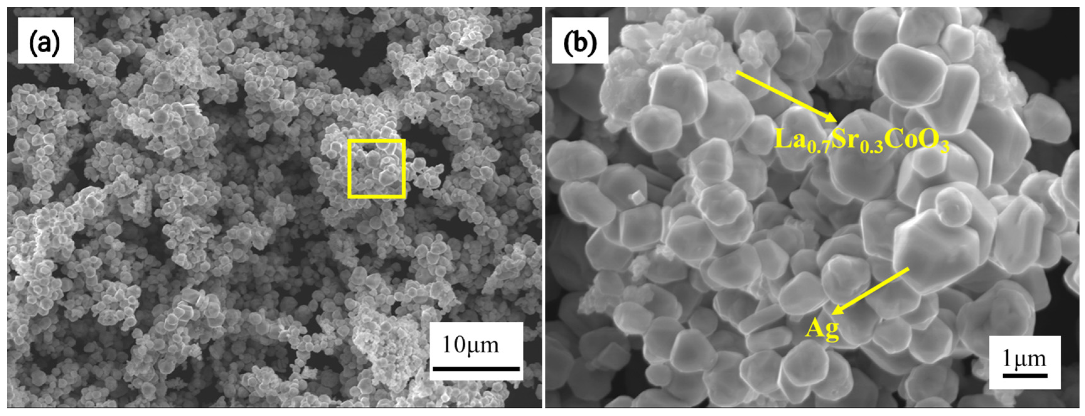
Figure 2a shows an SEM image that reveals a homogeneously distributed powder with a uniform particle size, demonstrating the effectiveness of the ball milling process in achieving a well-mixed composite. Figure 2b provides a magnified view that further confirms the successful dispersion of La0.7Sr0.3CoO3 particles within the Ag matrix. The Ag particles can be identified by their larger size and relatively smooth, rounded morphology. These particles are generally more spherical and exhibit a uniform appearance. In contrast, the La₀.₇Sr0.3CoO₃ particles are smaller and display a more angular, irregular morphology, with rougher surfaces.
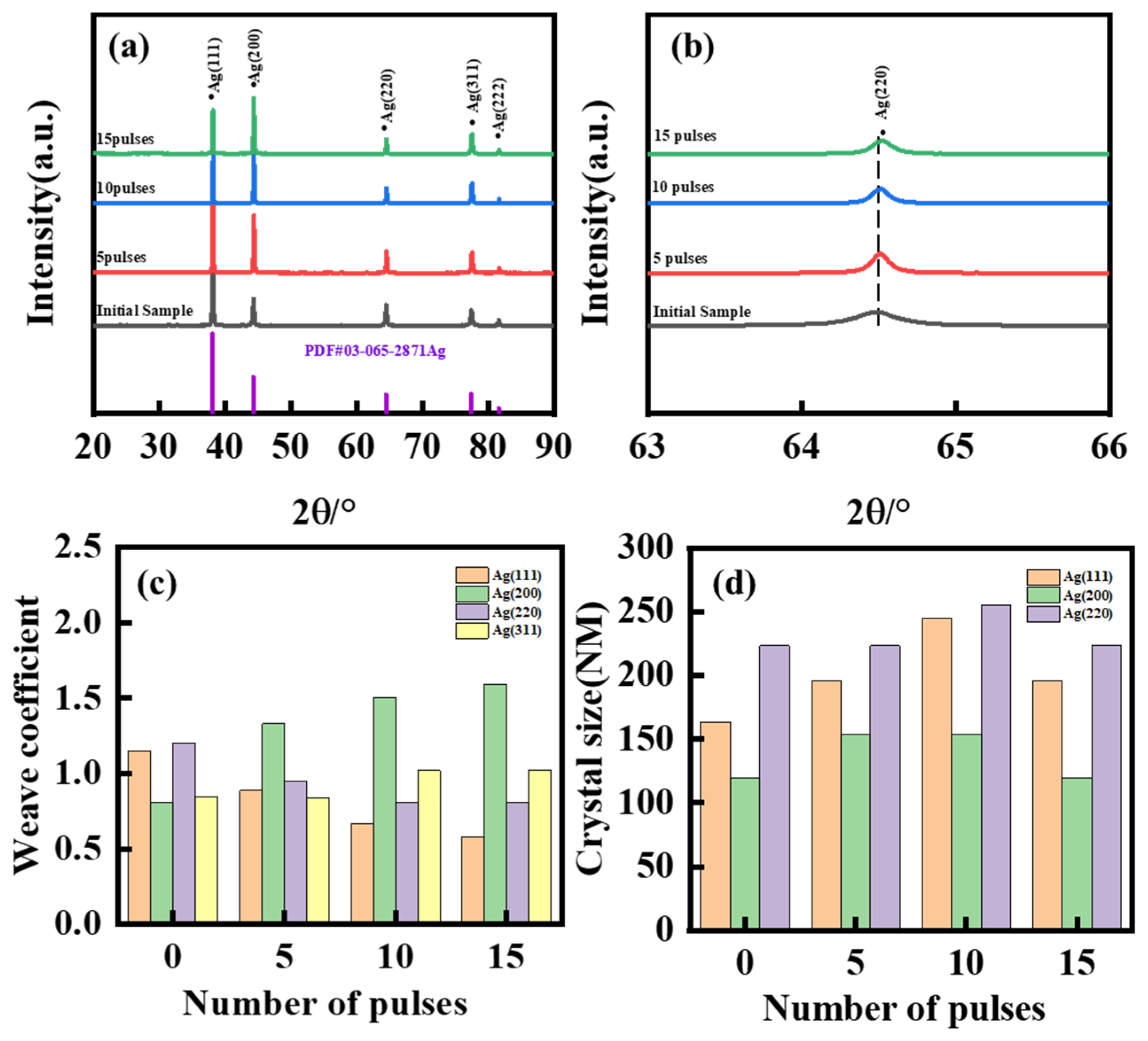
Figure 3 shows the XRD diffraction pattern of the surface of the Ag-10La0.7Sr0.3CoO3 composite before and after the HCPEB treatment. It can be seen from Figure 3a that, compared with the original sample, no new phases are formed on the surface of the Ag-10La0.7Sr0.3CoO3 composite after the electron beam treatment, except for silver and lanthanum–strontium–cobalt–oxygen phases. In addition, the local magnification in Figure 3b shows that the diffraction peak is shifted to a high angle after the HCPEB treatment. This may be attributed to the remelting of the material surface induced by the electron beam, which is prone to generating residual compressive stress on the material surface during the subsequent rapid solidification process. This compressive stress will shrink the crystal lattice, leading to a decrease in the spacing between the crystal planes. Consequently, the diffraction peak will shift to the right. Moreover, as the number of HCPEB pulse cycles increases, the peak’s intensity rises, suggesting an improvement in crystallinity or a more pronounced alignment of grains along the (311) orientation. However, further XRD pattern analysis revealed a significant increase in the intensity of the diffraction peaks for some specific crystal planes. The diffraction peak intensities of samples in their (200) and (311) crystal planes increase significantly with the increase in the number of pulses. At the same time, the (200) diffraction peak of the sample subjected to 15 pulse treatments was the strongest peak, indicating that the crystal surface may have a preferential orientation [29]. To qualitatively assess the extent of the preferential growth of Ag grains in the modified layer, the texture coefficient (TC) was utilized for its characterization, as outlined in Equation (1). If the TC values for all diffraction planes of silver are identical, this suggests that the crystal orientation is random, with no tendency for Ag grains to preferentially grow along any specific crystal plane. Conversely, differing TC values imply the presence of a preferred orientation in the growth of Ag grains.
TC ( h k l ) j = ( I ( h k l ) j / I ( h k l ) j , 0 ) ( 1 / n ) i = 1 n ( I ( h k l ) i / I ( h k l ) i , 0 ) ,
where I is the diffraction peak intensity of the silver–lanthanum–strontium–cobalt–oxygen composite surface grain for the (hkl) plane, both before and after the high-current pulsed electron beam (HCPEB) treatment. It reflects the strength of the reflection from the crystallographic plane (hkl), indicating its presence and alignment within the material’s structure, and is the diffraction peak intensity of the standard Ag-10La0.7Sr0.3CoO3 composite surface for the (hkl) plane. This serves as a reference intensity, representing the ideal state of the material without any HCPEB treatment, thereby providing a baseline for comparison. n is the number of selected diffraction peaks, corresponding to the different crystallographic planes analyzed in the material. It ensures that the texture coefficient calculation is based on a comprehensive analysis of the material’s crystal structure [30,31,32]. The obtained TC (hkl) values are plotted in Figure 3c, showing that the selective orientation of the HCPEB-treated (200) crystal surface is obvious. As evidenced by the rightward shift of the XRD peak positions and intensity changes, HCPEB induced lattice strain and facet-selective orientation. During the HCPEB treatment, the beam generates high temperatures on the sample surface, leading to localized melting and rapid solidification. Due to thermal gradients, grains may rapidly grow in specific directions during cooling, leading to their selective orientation.
Figure 3d depicts the variations in the sizes of silver crystal planes (Ag(111), Ag(200), Ag(220)) on the surface of Ag-10La0.7Sr0.3CoO3 composites subjected to different pulse durations. The crystallite size was determined using the Scherrer equation [33,34]. The precision of these measurements is affected by several factors, including instrumental broadening, the accuracy of peak fitting, and the quality of the sample’s preparation. By comprehensively accounting for these variables, the uncertainty associated with the crystallite size measurements is estimated to be around ±5%. The results reveal a significant influence of pulse duration on the crystal plane sizes. Specifically, the Ag(111) plane exhibits relatively stable size changes, with a slight increase as the pulse duration extends, suggesting an enhancement in crystal structure stability. The Ag(200) plane demonstrates a pronounced increase in size, particularly at intermediate pulse durations, indicating potential crystal growth and reorientation. Similarly, the Ag(220) plane shows a steady increase in size with increasing pulse duration, achieving stability at longer pulses, which reflects its enhanced crystal stability under these conditions. These observations suggest that extended pulse durations during an HCPEB treatment contribute to the optimization and stabilization of the microstructure in the silver phase of the composite.
Figure 4 shows the surface topography of the samples before and after the HCPEB treatment. As shown in Figure 4a, which displays the surface micromorphology of the sample without the HCPEB treatment, the La0.7Sr0.3CoO3 phase is not uniformly distributed in the silver matrix; there is a localized bias phenomenon (Figure 2). Further, there are some pore structures on the material’s surface. Because sintering was performed at a low temperature, the flowability of the powder was high. Consequently, insufficient bonding between powder particles may have led to a poor filling, thereby generating pores. The surface morphology of the samples changed significantly after five treatments. As shown in Figure 4b, the surface appeared to have a long, ridge-like grain and there were many craters of different sizes, shapes, and distributions, similar to volcanic eruptions. A study [35] has revealed that the formation of this structure is attributable to defects in the material components that undergo complex crystallization and temperature-induced changes during powder metallurgy. Figure 4c shows the surface of the sample after 10 treatments, which exhibits a more uniform ridge pattern and reduced number of surface pits compared with samples treated five times. Figure 4d shows the surface of the sample after 15 treatments. Compared to that in the other samples, the number of pits significantly reduced, the size of the pits is considerably reduced, and ridge-like lines have become more gentle and regular.
The EDS patterns of Ag, La, Sr, Co, and O are shown in Figure 5b–f,h–l. As shown in these figures, Ag becomes inhomogeneous after 15 HCPEB treatments, which may be attributed to the remelting and rapid solidification on material surface triggered by the HCPEB. This further leads to the redistribution of Ag in the matrix material. The HCPEB can induce microstructural changes within the material, leading to Ag’s enrichment and segregation. This phenomenon may be attributed to the low melting point and high diffusion coefficient of Ag. However, La is uniformly distributed [36]. The increased distribution uniformity of the La elements in the material may be related to the homogenization effect induced during the HCPEB treatment [37,38]. The multiple impacts of the pulsed electron beam can promote the redistribution of this element in the material, thus reducing its existing inhomogeneity. In addition, the high melting point and low diffusion coefficient of La elements make them more stable during high-temperature remelting, and the multiple pulsed electron beams help to eliminate localized elemental concentration gradients.
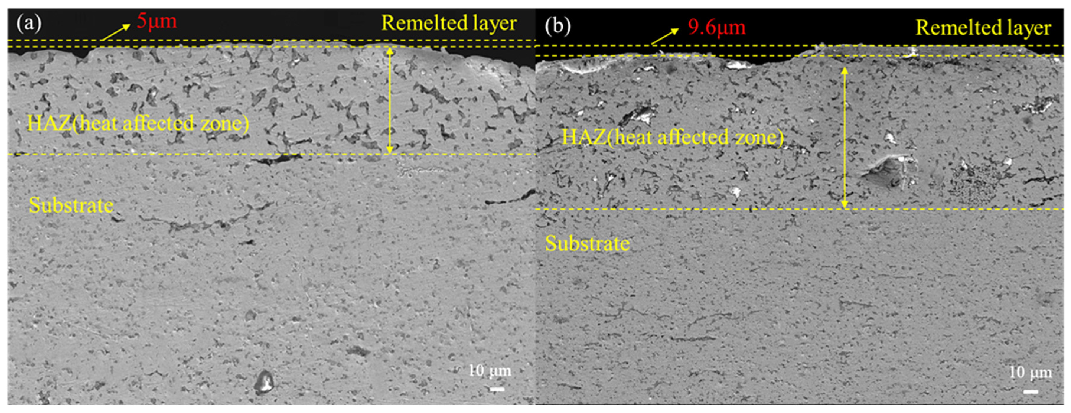
Figure 6 shows the cross-sectional SEM images of Ag-10La0.7Sr0.3CoO3 specimens after HCPEB irradiation. The cross-sectional view reveals three distinct layers: the remelted layer, the heat-affected zone (HAZ), and the substrate. The remelted zone is characterized by a fine-grained or featureless microstructure that results from rapid melting and solidification during the HCPEB irradiation process. This region appears more homogeneous and smoother than the heat-affected zone (HAZ) due to the complete melting and subsequent recrystallization of the material [39]. In both Figure 6a,b, this zone is located at the topmost layer and is delineated by yellow dashed lines and labeled as the “Remelted layer”. The HAZ is situated immediately below the remelted zone and is distinguished by its partially altered microstructure [40]. Unlike the remelted zone, the material in the HAZ does not undergo complete melting; instead, it experiences thermal effects that lead to grain growth, phase transformations, or other modifications. This region exhibits more variability in its grain size and contrast differences in the SEM images. The remelted layer’s thickness increases from approximately 5 µm after 5 pulses to about 9.6 µm following 15 pulses. This thickening with increasing HCPEB pulses is attributed to heat accumulation and enhanced energy diffusion, which progressively melts and modifies the surface. The consistent formation of the HAZ beneath the remelted layer confirms that there is an effective microstructural modification, while the substrate’s integrity remains intact.
Figure 7 shows the microhardness values of the sample surface according to different numbers of treatments. The microhardness of the pristine sample is low (62.3 HV). This may be attributed to the looser surface structure of the sample before treatment, its larger grains, and its weaker bonding strength. However, the hardness value gradually increased with an increasing number of treatments. After 15 treatments, the Vickers hardness attained its maximum value of 85.2 HV, indicating a 36.76% increase in hardness. Two main factors enhance hardness after the HCPEB treatment. First, the electron beam deposits a large amount of energy on the surface of the material during the HCPEB treatment, leading to the rapid heating and melting of localized areas on the surface. The melted material rapidly cools and solidifies at the end of the pulse, forming fine grains and dense microstructures. The fine grains and dense structure increase the number of grain boundaries and impede the movement of dislocations, increasing the surface’s hardness and strength [41,42]. Second, under high-temperature conditions, the HCPEB treatment induces material recrystallization, which subsequently leads to the rearrangement and strengthening of grain boundaries. This grain boundary strengthening mechanism can effectively increase the hardness of the material [43,44].
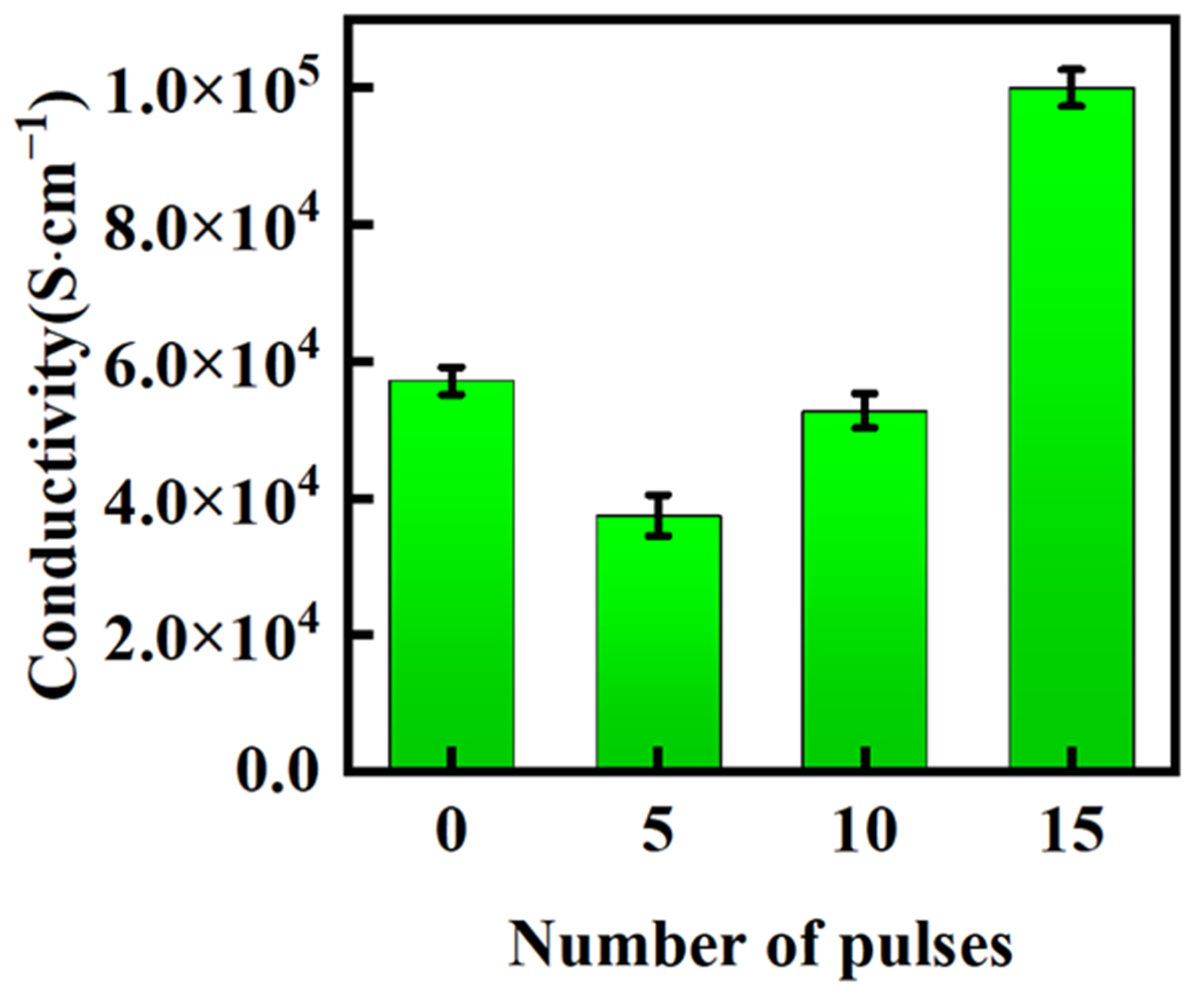
Figure 8 shows the variation of the surface conductivity of Ag-10La0.7Sr0.3CoO3 composites according to the number of pulses applied. The results show that the conductivity of the untreated sample is low, at 5.72 × 10⁴ S·cm−1, due to the flat and uniform surface structure present. After five treatments, the conductivity decreases significantly and attains its lowest value. After 10 treatments, the conductivity is increased compared to that after five treatments. Further, 15 pulse treatments yielded the highest value for conductivity, which was 74.8% higher than the conductivity of the original sample. The reasons for the increase in conductivity were analyzed: first, the untreated samples possessed relatively large grains and a small number of grain boundaries, resulting in a low initial conductivity. After five treatments, the conductivity decreased due to the increased surface roughness and porosity of the sample, as shown in Figure 4b. After 10 and 15 treatments, the grains were further refined, the number of grain boundaries increased, and the distribution of defects was more homogeneous, leading to an increase in the conductivity, especially after 15 treatments, where the optimization of grain boundaries and defects reached an optimal state, as shown in Figure 4d, resulting in the highest conductivity. Second, the HCPEB treatment generates many defects (e.g., dislocations and vacancies) on the material’s surface. These defects may hinder the movement of carriers and reduce its conductivity at this initial stage. However, as the number of treatments increases, these defects will gradually heal and reach an equilibrium state, resulting in increased conductivity. These findings provide an important reference for an in-depth understanding of the microstructural changes and defect dynamics induced by the HCPEB treatment.
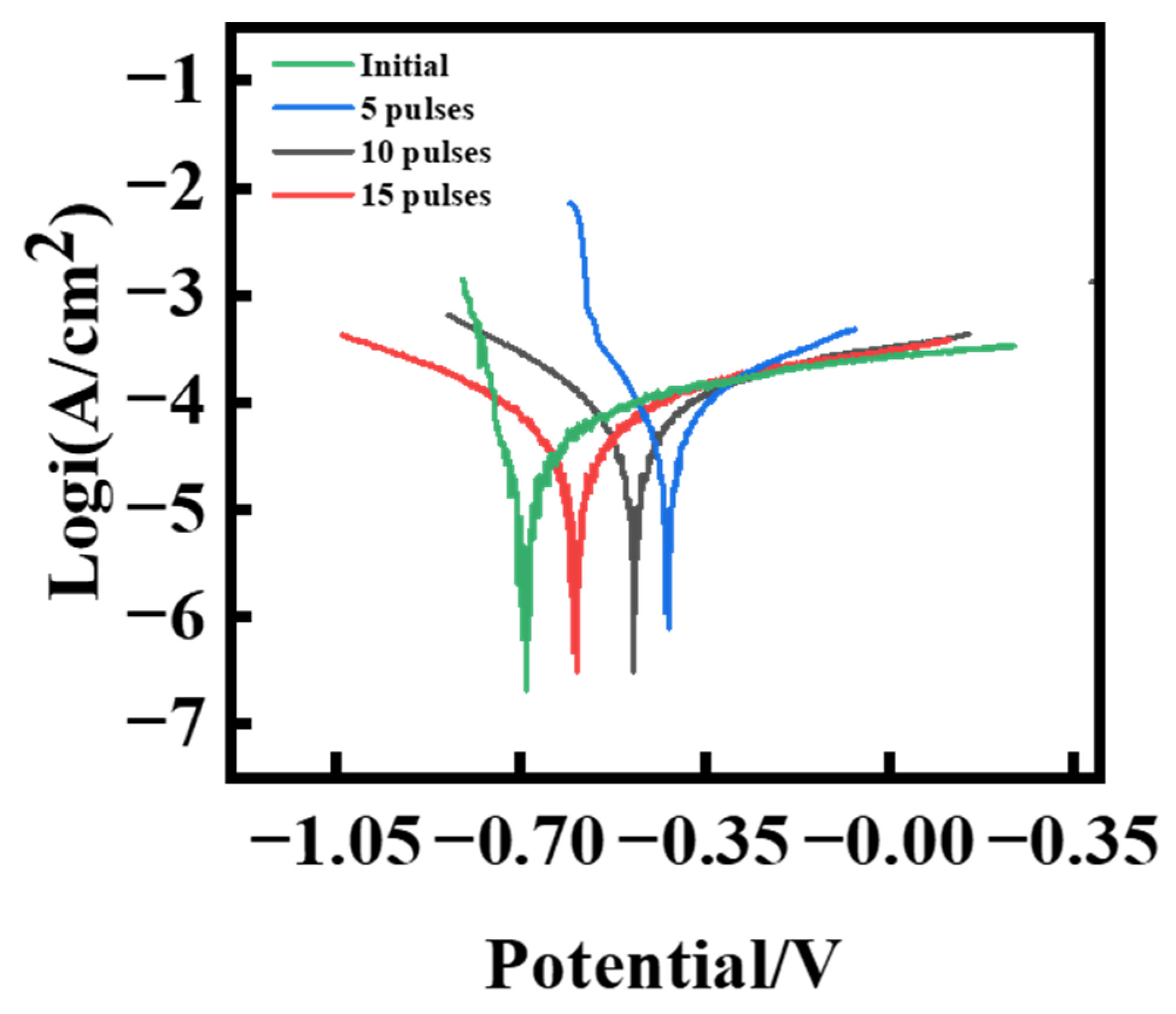
The polarization curves of the original and HCPEB-treated Ag-10La0.7Sr0.3CoO3 samples in a 3.5 wt.% NaCl solution are shown in Figure 9. The corrosion current density and corrosion voltage calculated using the Tafel extrapolation method are shown in Table 3 [45,46]. The original sample showed a low corrosion voltage and high corrosion propensity. The polarization curve exhibited a large slope, indicating a high corrosion rate. The corrosion voltage (Ecorr) and corrosion current density (Icorr) of HCPEB-treated samples increased with an increasing number of treatments. The Icorr increased slightly after 10 treatments, which may be attributed to the re-appearance of defects or increased surface roughness in some areas, which was caused by the treatment. After 15 treatments, the Ecorr increased significantly, to −122.1 V, and the Icorr decreased to 2.754 × 10⁻⁵ A/cm2, indicating a significant improvement in corrosion resistance. This may be due to the more uniform surface, as shown in Figure 4d, which facilitates the formation of a protective oxide film, thereby reducing the electrochemical activity of the metal. The HCPEB treatment significantly improved the corrosion resistance of the Ag-10La0.7Sr0.3CoO3 composites because of three reasons: First, the instantaneous high temperature of the HCPEB rapidly melted and cooled the material surface. This rapid thermal cycle helped in the formation of a dense surface layer, which blocked the diffusion of corrosive media such as Cl ions, reducing the corrosion rate [47]. Second, the treatment reconstructed the material surface using the HCPEB. The XRD results showed that the grains on the sample surface were refined and the number of grain boundaries was increased. These grain boundaries act as corrosion barrier sites, which can effectively prevent the penetration of corrosive media. Finally, the HCPEB treatment may promote the formation of an oxide layer on the sample surface. This oxide layer possesses good chemical stability and can effectively isolate corrosive media [48].

4. Conclusions

In this paper, the microstructure and mechanical properties of Ag-10La0.7Sr0.3CoO3 composites were characterized after an HCPEB treatment; the main findings are as follows:
(1)
After five HCPEB treatments, local melting and rapid solidification occurred on the sample surface, resulting in the formation of many volcanic pits. After 15 treatments, the number of pits decreased, and there was obvious recrystallization and the formation of new grains. A greater number of treatments may lead to deeper melting and solidification and extensive surface modification.
(2)
The hardness of the material surface increased with an increasing number of treatments. The increase in hardness was attributed to the reinforcement of a uniform phase distribution, surface remelting and recrystallization, and a reduction in the number of pores.
(3)
The improvement in corrosion resistance was mainly due to the refinement of the surface’s microstructure and the introduction of residual compressive stress.
(4)
The observed improvement in electrical conductivity was attributed to the grain refinement, defect formation, and surface healing of the samples after the HCPEB treatment.

Author Contributions

Conceptualization, H.Z. and B.G.; methodology, H.Z. and L.W.; software, W.S. and P.L.; validation, H.Z., B.G. and X.L.; formal analysis, H.Z.; investigation, H.Z. and H.L.; resources, B.G.; data curation, H.Z. and W.S.; writing—original draft preparation, H.Z. and B.G.; writing—review and editing, H.Z.; visualization, W.S.; supervision, B.G.; project administration, B.G.; funding acquisition, B.G. All authors have read and agreed to the published version of the manuscript.

Funding

This work was supported by the National Natural Science Foundation of China (51671052), the Fundamental Research Funds for the Central Universities (N182502042), and the Liao Ning Revitalization Talents Program (XLYC1902105).

Institutional Review Board Statement

Not applicable.

Informed Consent Statement

Not applicable.

Data Availability Statement

Data will be made available upon request from the corresponding author.

Conflicts of Interest

The authors declare no conflicts of interest.

References

  1. Ćosović, V.; Ćosović, A.; Talijan, N.; Živković, D.; Manasijević, D.; Minić, D. Improving dispersion of SnO2 nanoparticles in Ag–SnO2 electrical contact materials using template method. J. Alloys Compd. 2013, 567, 33–39. [Google Scholar] [CrossRef]
  2. Wei, Z.; Zhang, L.; Shen, T.; Qiao, Z.; Yang, H.; Fan, X.; Chen, L. Effects of Oxide-Modified Spherical ZnO on Electrical Properties of Ag/ZnO Electrical Contact Material. J. Mater. Eng. Perform. 2016, 25, 3662–3671. [Google Scholar] [CrossRef]
  3. Chen, S.; Wang, J.; Yuan, Z.; Wang, Z.; Du, D. Microstructure and arc erosion behaviors of Ag-CuO contact material prepared by selective laser melting. J. Alloys Compd. 2021, 860, 158494. [Google Scholar] [CrossRef]
  4. Buyanova, E.S.; Shafigina, R.R.; Morozova, M.V.; Emel’yanova, Y.V.; Khisametdinova, V.V.; Zhukovskii, V.M.; Petrova, S.A.; Tarakina, N.V. Electrochemical characteristics, thermal and chemical compatibility in the La0.7Sr0.3CoO3 electrode-γ-BIFEVOX electrolyte system. Russ. J. Inorg. Chem. 2013, 58, 554–558. [Google Scholar] [CrossRef]
  5. Zhao, D.; Gao, Z.; Xian, H.; Xing, L.; Yang, Y.; Tian, Y.; Ding, T.; Jiang, Z.; Zhang, J.; Zheng, L.; et al. Addition of Pd on La0.7Sr0.3CoO3 Perovskite To Enhance Catalytic Removal of NOx. Ind. Eng. Chem. Res. 2018, 57, 521–531. [Google Scholar] [CrossRef]
  6. Li, R.; Kumar, P.; Mahendiran, R. Critical behavior in polycrystalline La0.7Sr0.3CoO3 from bulk magnetization study. J. Alloys Compd. 2016, 659, 203–209. [Google Scholar] [CrossRef]
  7. Liu, N.; Yan, G.; Guo, H.; Mao, Q.; Cai, Z. Effect of Dy Doping on Magnetism of La0.7Sr0.3CoO3 System. Rare Met. Mater. Eng. 2010, 39, 874–877. [Google Scholar] [CrossRef]
  8. Liu, P.; Liu, J.; Cheng, S.; Cai, W.; Yu, F.; Zhang, Y.; Wu, P.; Liu, M. A high-performance electrode for supercapacitors: Silver nanoparticles grown on a porous perovskite-type material La0.7Sr0.3CoO3 substrate. Chem. Eng. J. 2017, 328, 1–10. [Google Scholar] [CrossRef]
  9. Mira, J.; Rivas, J.; Vázquez, M.; Ibarra, M.R.; Caciuffo, R.; Rodríguez, M.A.S. Field-induced magnetic anisotropy in La0.7Sr0.3CoO3. Europhys. Lett. 2003, 62, 433–438. [Google Scholar] [CrossRef]
  10. Wang, X.; Huang, K.; Yuan, L.; Li, S.; Ma, W.; Liu, Z.; Feng, S. Molten Salt Flux Synthesis, Crystal Facet Design, Characterization, Electronic Structure, and Catalytic Properties of Perovskite Cobaltite. ACS Appl. Mater. Interfaces 2018, 10, 28219–28231. [Google Scholar] [CrossRef]
  11. Sun, H.; Lordi, V.; Takamura, Y.; Samanta, A. Unraveling the Correlation between the Interface Structures and Tunable Magnetic Properties of La1-xSrxCoO3-δ/La1-xSrxMnO3-δ Bilayers Using Deep Learning Models. ACS Appl. Mater. Interfaces 2024, 16, 30166–30175. [Google Scholar] [CrossRef] [PubMed]
  12. Zheng, X.; Wang, D.; Shen, T.; Shao, Z.; Yang, H.; Yang, F. Improving Interfacial Wettability, Physical, and Mechanical Properties of Ag/La1-xSrxCoO3 Electrical Contact Materials by In Situ Cu-Doping. J. Mater. Eng. Perform. 2023, 33, 7892–7903. [Google Scholar] [CrossRef]
  13. Liu, Y.Y.; Hong, L. Fabrication and characterization of (Pd/Ag)-La0.2Sr0.8CoO3-δ composite membrane on porous asymmetric substrates. J. Membr. Sci. 2003, 224, 137–150. [Google Scholar] [CrossRef]
  14. Li, G.; Fang, X.; Feng, W.; Liu, J. In situ formation and doping of Ag/SnO2 electrical contact materials. J. Alloys Compd. 2017, 716, 106–111. [Google Scholar] [CrossRef]
  15. Kwon, S.G.; Piao, Y.; Park, J.; Angappane, S.; Jo, Y.; Hwang, N.-M.; Park, J.-G.; Hyeon, T. Kinetics of monodisperse iron oxide nanocrystal formation by "heating-up" process. J. Am. Chem. Soc. 2007, 129, 12571–12584. [Google Scholar] [CrossRef]
  16. Zhao, Q.; Liu, H.; Wu, C.; Li, N.; Jiang, Y.; Yi, D. Preferential oxidation of intermetallic compounds in Ag-2Sn-4La alloy. Corros. Sci. 2018, 143, 177–186. [Google Scholar] [CrossRef]
  17. Guo, X.; Yang, Y.; Song, K.; Shaolin, L.; Jiang, F.; Wang, X. Arc erosion resistance of hybrid copper matrix composites reinforced with CNTs and micro-TiB2 particles. J. Mater. Res. Technol. 2021, 11, 1469–1479. [Google Scholar] [CrossRef]
  18. Toozandehjani, M.; Matori, K.A.; Ostovan, F.; Abdul Aziz, S.; Mamat, M.S. Effect of milling time on the microstructure, physical and mechanical properties of Al-Al2O3 nanocomposite synthesized by ball milling and powder metallurgy. Materials 2017, 10, 1232. [Google Scholar] [CrossRef]
  19. Karabacak, A.H.; Canakci, A.; Ozkaya, S.; Tunc, S.A.; Cevik, Z.A.; Yalcin, E.D. The effects of different types and ratios of reinforcement, and machining processes on the machinability of Al2024 alloy nanocomposites. J. Compos. Mater. 2023, 57, 2811–2827. [Google Scholar] [CrossRef]
  20. Kumar, M.; Kumar, R.; Bhaskar, S.; Kumar, A. Parametric Optimization and Ranking Analysis of AA2024-Al2O3/AlN Alloy Composites Fabricated Via Stir Casting Route Under Dry Sliding Wear Investigation. Int. J. Metalcast. 2024, 18, 667–687. [Google Scholar] [CrossRef]
  21. Liang, X.; Meng, X.; Ni, P.; Zhao, Z.; Deng, X.; Chen, G.; Chen, Y.; Li, S.; Wu, S.; Liu, J.; et al. Effect of feedstock bimodal powder mixture and infiltration process on mechanical behaviour of binder jetting processed 316L stainless steel. Powder Metall. 2023, 66, 387–402. [Google Scholar] [CrossRef]
  22. Liu, Z.; Gao, B.; Zhao, P.; Fu, H.; Kamali, A.R. Magnetic luffa/graphene/CuFe2O4 sponge for efficient oil/water separation. Sep. Purif. Technol. 2024, 337, 126347. [Google Scholar] [CrossRef]
  23. Anikeev, S.G.; Shabalina, A.V.; Kulinich, S.A.; Artyukhova, N.V.; Korsakova, D.R.; Yakovlev, E.V.; Vlasov, V.A.; Kokorev, O.V.; Hodorenko, V.N. Preparation and Electron-Beam Surface Modification of Novel TiNi Material for Medical Applications. Appl. Sci. 2021, 11, 4372. [Google Scholar] [CrossRef]
  24. Wang, L.; Gao, B.; Sun, Y.; Zhang, Y.; Hu, L. Effect of High Current Pulsed Electron Beam (HCPEB) on the Organization and Wear Resistance of CeO2-Modified Al-20SiC Composites. Materials 2023, 16, 4656. [Google Scholar] [CrossRef] [PubMed]
  25. Zhang, Y.; Zhu, G.L.; Gao, B.; Wang, L.; Li, Z.; Hu, L.; Shi, Z.; Yin, Q. Effect of High-Current Pulsed Electron Beam on Properties of Graphene-Modified Aluminum Titanium Carbide Composites. Materials 2022, 15, 7879. [Google Scholar] [CrossRef]
  26. Hao, Y.; Gao, B.; Tu, G.F.; Cao, H.; Hao, S.Z.; Dong, C. Surface modification of Al–12.6Si alloy by high current pulsed electron beam. Appl. Surf. Sci. 2012, 258, 2052–2056. [Google Scholar] [CrossRef]
  27. Sun, P.; Zhang, C.; Cai, J.; Lyu, P.; Jin, Y.; Guan, Q. Properties of a rapidly solidified Ni–Nb layer prepared using a high-current pulsed electron beam. Vacuum 2020, 177, 109362. [Google Scholar] [CrossRef]
  28. Han, Z.; Li, X.; Lu, B.; Yan, H. Influence of HCPEB Bombardment on the Microstructure and Corrosion Resistance of CMAS of Thermal Barrier Coating. Rare Met. Mater. Eng. 2023, 52, 2147–2153. [Google Scholar] [CrossRef]
  29. Zhang, Y.; Liu, Z.; Zhang, X.; Wang, Q.; Wang, Q.; Wang, H.; Jiang, W.; Liu, S.; Liu, C.; Wang, N.; et al. The formation mechanism of (001) preferred orientation for anatase TiO2 film prepared by DC pulsed magnetron sputtering. Vacuum 2021, 190, 110287. [Google Scholar] [CrossRef]
  30. Elmkhah, H.; Zhang, T.F.; Abdollah-zadeh, A.; Kim, K.H.; Mahboubi, F. Surface characteristics for the TiAlN coatings deposited by high power impulse magnetron sputtering technique at the different bias voltages. J. Alloys Compd. 2016, 688, 820–827. [Google Scholar] [CrossRef]
  31. Peng, B.; Xu, Y.X.; Du, J.W.; Chen, L.; Kim, K.H.; Wang, Q. Influence of preliminary metal-ion etching on the topography and mechanical behavior of TiAlN coatings on cemented carbides. Surf. Coat. Technol. 2022, 432, 128040. [Google Scholar] [CrossRef]
  32. Staia, M.H.; Puchi, E.S.; Lewis, D.B.; Cawley, J.; Morel, D. Microstructural characterization of chemically vapor deposited TiN coating. Surf. Coat. Technol. 1996, 86–87, 432–437. [Google Scholar] [CrossRef]
  33. Sahadat Hossain, M.; Ahmed, S. Easy and green synthesis of TiO2 (Anatase and Rutile): Estimation of crystallite size using Scherrer equation, Williamson-Hall plot, Monshi-Scherrer Model, size-strain plot, Halder-Wagner Model. Results Mater. 2023, 20, 100492. [Google Scholar] [CrossRef]
  34. Garg, A.; Parmar, L.K.; Garg, T.; Dager, H.S.; Bhardwaj, P.; Yadav, A. Structural analysis and dielectric behavior of low-temperature synthesized nickel cobaltite. Chem. Phys. Impact 2024, 8, 100457. [Google Scholar] [CrossRef]
  35. Sun, Y.; Gao, B.; Hu, L.; Li, K.; Zhang, Y. Effect of CeO2 on Corrosion Resistance of High-Current Pulsed Electron Beam Treated Pressureless Sintering Al-20SiC Composites. Coatings 2021, 11, 707. [Google Scholar] [CrossRef]
  36. Mackowski, K.N.; Hargather, C.Z. A first-principles study of self-diffusion and dilute solute diffusion of Au in FCC Ag. Comput. Mater. Sci 2021, 193, 110414. [Google Scholar] [CrossRef]
  37. Chai, L.; Chen, B.; Wang, S.; Zhang, Z.; Murty, K.L. Microstructural, textural and hardness evolution of commercially pure Zr surface-treated by high current pulsed electron beam. Appl. Surf. Sci. 2016, 390, 430–434. [Google Scholar] [CrossRef]
  38. Guan, R.-G.; Tie, D. A Review on Grain Refinement of Aluminum Alloys: Progresses, Challenges and Prospects. Acta Metall. Sin. 2017, 30, 409–432. [Google Scholar] [CrossRef]
  39. Lyu, P.; Chen, Y.; Liu, Z.; Cai, J.; Zhang, C.; Jin, Y.; Guan, Q.; Zhao, N. Surface modification of CrFeCoNiMo high entropy alloy induced by high-current pulsed electron beam. Appl. Surf. Sci. 2020, 504, 144453. [Google Scholar] [CrossRef]
  40. Wang, H.; Li, L.; Qiu, S.; Zhai, W.; Li, Q.; Hao, S. Evolution of Microstructure at the Surface of 40CrNiMo7 Steel Treated by High-Current Pulsed Electron Beam. Coatings 2020, 10, 311. [Google Scholar] [CrossRef]
  41. Guan, Q.; Han, J.; Zhou, S.; Guan, J.; Zhang, C.; Cao, F.; Chen, X. Improved mechanical and tribological properties of TiAlN coatings by high current pulsed electron beam irradiation. Int. J. Refract. Met. Hard Mater 2024, 118, 106435. [Google Scholar] [CrossRef]
  42. Jiang, W.; Sun, Y.; Dai, H.; Wang, E. Enhanced surface quality and properties of cold spray Al coating by high current pulsed electron beam treatment. Nucl. Instrum. Methods Phys. Res. Sect. B 2023, 542, 7–13. [Google Scholar] [CrossRef]
  43. Feng, Z.; Wang, J.; Zhang, F.; Liu, J.; Hu, J.; Chai, L.; Song, B.; Guo, N.; Guo, S.; Yao, Z. Effect of high current pulsed electron beam on surface microstructure and properties of cold-rolled austenitic stainless steel. J. Mater. Res. Technol. 2024, 29, 1183–1193. [Google Scholar] [CrossRef]
  44. Zhang, C.; Ji, X.; Wang, J.; Lu, L.; Yang, Z.; Lyu, P.; Guan, Q.; Cai, J. Amorphization and Nano-Crystallization of Ni-Nb Coating on GH3039 Alloys by High Current Pulsed Electron Beam. J. Nanomater. 2021, 11, 347. [Google Scholar] [CrossRef]
  45. Zhao, Y.T.; Guo, X.P.; Zhao, G.Y.; Dong, Z.H.; Chen, G.Z. Determination of tafel slopes from coulostatically induced transients and its integral alogrithm. Acta Phys. Chim. Sin. 2005, 21, 93–97. [Google Scholar] [CrossRef]
  46. Lindbergh, G.; Zhu, B.H. Corrosion behaviour of high aluminium steels in molten carbonate in an anode gas environment. Electrochim. Acta 2001, 46, 1131–1140. [Google Scholar] [CrossRef]
  47. Lyu, P.; Peng, T.; Miao, Y.; Liu, Z.; Gao, Q.; Zhang, C.; Jin, Y.; Guan, Q.; Cai, J. Microstructure and properties of CoCrFeNiMo0.2 high-entropy alloy enhanced by high-current pulsed electron beam. Surf. Coat. Technol. 2021, 410, 126911. [Google Scholar] [CrossRef]
  48. Cai, J.; Zu, Z.; Li, C.; Lyu, P.; Guan, Q.; Li, Y. Hot Corrosion Behavior of Arc Ion Plating NiCoCrAlYSiHf Coating Via High-Current Pulsed Electron Beam. Oxid. Met. 2020, 94, 569–586. [Google Scholar] [CrossRef]
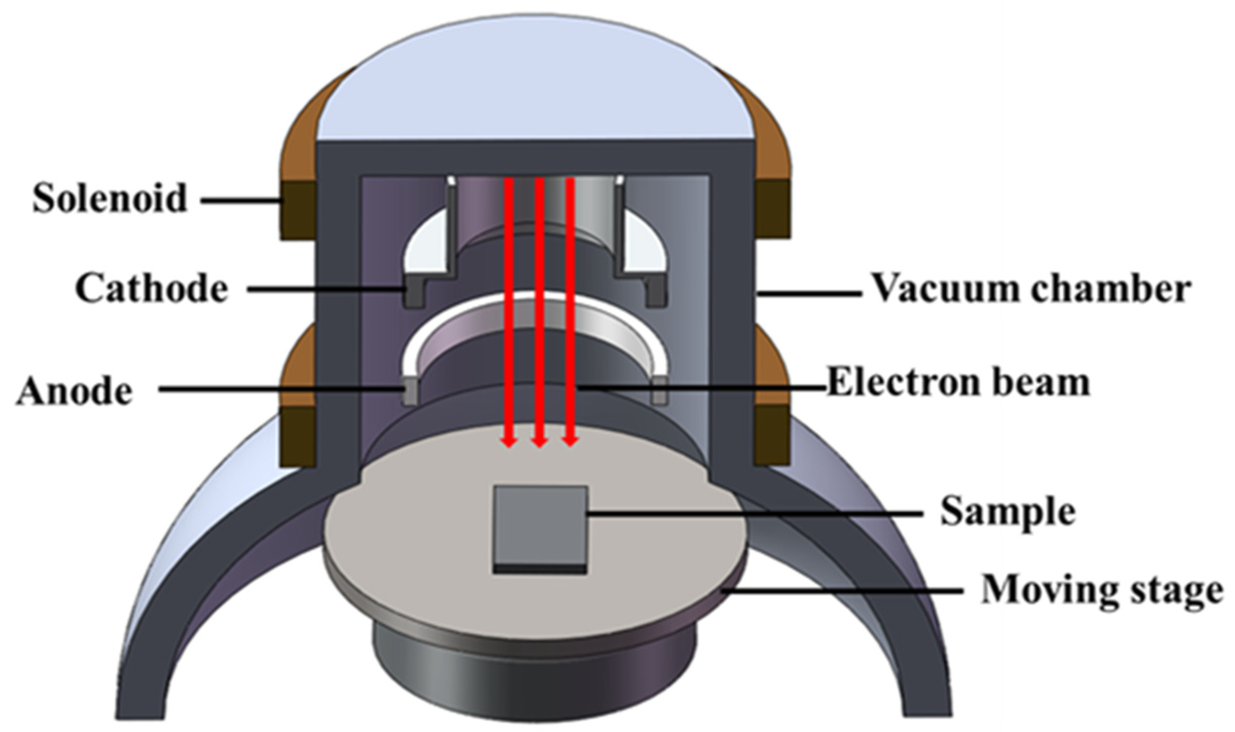
Figure 1. High-current pulsed electron beam device’s structure.
Surfaces 07 00048 g001
Figure 2. Mixing powder after ball milling: (a) Ag-10La0.7Sr0.3CoO3 mixing powder, (b) magnified image.
Surfaces 07 00048 g002
Figure 3. Complete XRD pattern of the Ag-10La0.7Sr0.3CoO3 composite’s surface before and after high-current pulsed electron beam treatment (a); (b) magnified image; (c) the texture coefficient of the silver crystal plane on the surface of the Ag-10La0.7Sr0.3CoO3 composite after different numbers of pulses; (d) the size of the silver crystal planes on the surface of the Ag-10La₀.₇Sr₀.₃CoO₃ composites after different numbers of pulses.
Surfaces 07 00048 g003
Figure 4. Morphology of Ag-10La0.7Sr0.3CoO3 samples before and after high-current pulsed electron beam treatment: (a) original sample and samples after (b) 5, (c) 10, and (d) 15 treatments.
Surfaces 07 00048 g004
Figure 5. (af) are the pictures of the distribution of elements in Figure 4a; (gl) are the pictures of the distribution of elements in Figure 4d.
Surfaces 07 00048 g005
Figure 6. Cross-sectional SEM images of the HCPEB-irradiated Ag-10La0.7Sr0.3CoO3 samples subjected to 5 pulses (a) and 15 pulses (b).
Surfaces 07 00048 g006
Figure 7. Surface microhardness of Ag-10La0.7Sr0.3CoO3 composites subjected to different numbers of pulses.
Surfaces 07 00048 g007
Figure 8. Surface conductivity of Ag-10La0.7Sr0.3CoO3 composites after different numbers of treatments.
Surfaces 07 00048 g008
Figure 9. Electrokinetic potential polarization curves of original and HCPEB-treated Ag-10 La0.7Sr0.3CoO3 samples in a 3.5 wt.% NaCl solution.
Surfaces 07 00048 g009
Table 1. Composition and granularity of raw materials.
PowderPurity/wt.%Particle Size/µm
Ag99.93
La0.7Sr0.3CoO399.90.5–2
Table 2. Working parameters of the HCPEB system.
Acceleration Voltage (kV)Energy Density (J/cm2)Pulse Time
(μs)
Pulse Frequency
(Hz)
Peak Current Density (A/cm2)Electron Beam Cross-Sectional Area(cm2)Vacuum Level
(Pa)
30430.1500406 × 10−3
Table 3. Corrosion voltage and current density of Ag-10La0.7Sr0.3CoO3 composites before and after high-current pulsed electron beam treatment.
SamplesIcorr/A·cm−2Ecorr/V
Original6.614 × 10−5−0.6862
Treated 5 times5.051 × 10−5−0.7955
Treated 10 times5.521 × 10−5−0.5963
Treated 15 times2.754 × 10−5−0.1221
Disclaimer/Publisher’s Note: The statements, opinions and data contained in all publications are solely those of the individual author(s) and contributor(s) and not of MDPI and/or the editor(s). MDPI and/or the editor(s) disclaim responsibility for any injury to people or property resulting from any ideas, methods, instructions or products referred to in the content.