Review

Acoustic Black Holes in Structural Design for Vibration and Noise Control

Department of Mechanical Engineering, Stevens Institute of Technology, Hoboken, NJ 07030, USA
*
Author to whom correspondence should be addressed.
Acoustics 2019, 1(1), 220-251; https://doi.org/10.3390/acoustics1010014
Submission received: 2 October 2018 / Revised: 28 January 2019 / Accepted: 28 January 2019 / Published: 25 February 2019
(This article belongs to the Collection Featured Position and Review Papers in Acoustics Science)

Abstract

:
It is known that in the design of quieter mechanical systems, vibration and noise control play important roles. Recently, acoustic black holes have been effectively used for structural design in controlling vibration and noise. An acoustic black hole is a power-law tapered profile to reduce phase and group velocities of wave propagation to zero. Additionally, the vibration energy at the location of acoustic black hole increases due to the gradual reduction of its thickness. The vibration damping, sound reduction, and vibration energy harvesting are the major applications in structural design with acoustic black holes. In this paper, a review of basic theoretical, numerical, and experimental studies on the applications of acoustic black holes is presented. In addition, the influences of the various geometrical parameters and the configuration of acoustic black holes are presented. The studies show that the use of acoustic black holes results in an effective control of vibration and noise. It is seen that the acoustic black holes have a great potential for quiet design of complex structures.

1. Introduction

It is known that with the development of high-speed machinery, the control of unwanted vibration and noise are very important for their stability and reliability, as well as the environmental noise impact [1]. The two well-known methods for passive control of structural vibrations which also results in a reduction of noise are constrained layer damping and tuned dynamic absorbers [2]. The first method is based on using a viscoelastic layer attached to the structure and the second method needs an attachment of additional weight [3] to the target structure. Additionally, the active vibration control devices are also used for vibration damping [4]. However, these active methods require consistent input energy and more complex electro-mechanical design. Thus, for the reasons of limitation of size, budget, or weight, sometimes it is not possible, and also is not desirable, to use these above methods. There is always a need for an effective design of structures for vibration and noise control [5].
In recent times micro-devices, such as portable electronics and wireless remote sensors, are developed and widely used [6]. Most of these low-power electronics are powered by battery. However, even for the long-lasting batteries, they still need to be replaced because of their limited lifecycle. For some applications, such as sensors deployed in remote locations or inside the human body [7], it is challenging and costly, or even impractical. Energy harvesting is the process of capturing and converting ambient energy in the environment into usable electrical energy to extend the life of batteries, which makes the devices self-sustainable and environmental-friendly. Piezoelectric vibration energy harvesting (PVEH) is one of the typical energy harvesting methods. In the design of portable micro devices, the challenge is to reduce the weight and size of the host structure. Thus, approaches to increase the energy harvested from the vibrations of the host structures are desirable [8].
Recently, an approach for passive vibration control, acoustic black holes (ABH), has been developed. An ABH is usually a power-law tapered profile built on structures, such as beams, plates, and shells, where the vibration energy is concentrated due to the reduction of wave speed [9] (as shown in Figure 1). Therefore, due to this concentration effect of the ABH, the vibration energy can be absorbed by attaching small amount of damping material at the ABH location, which also results in reduced sound radiation. Additionally, the performance of energy harvesting is enhanced by attaching piezoelectric material at the ABH location [10]. An ABH is a tailing method which cuts material away from the host structure, and it also decreases the usage of damping layer, so it decreases the weight of host structures. Therefore, it is a good option for vibration and noise control of lightweight structures.
The ABH effect was first discovered by Pekeris in 1946 [11]. He exploited the central physical principle of ABH, namely the phase velocity of sound waves that propagate in a stratified fluid are progressively decreased to zero with increasing depth. In 1988 Mironov determined that a flexural wave propagates in a thin plate slows down and needs infinite time to reach a tapered edge [12]. Later, Krylov first used the name “acoustic black hole” to this effect [13], and applied ABH on beams and plates, also indicating that the ABH approach results in an increased amount of energy to be absorbed by adding a small amount of material attenuation near the ABH locations [14,15,16,17]. Then Conlon developed further numerical and experimental work to analyze the ABH effect on vibration and sound radiation of thin plates [18,19,20]. Later, researchers from different countries around the world worked on the ABH effect on structural vibration control, sound radiation, and vibration energy harvesting. Recently, a review on mechanics problem of the ABH structure was presented by Ji et al. [21]. This study systematically introduced the theoretical study on mechanics for 1D and 2D structures and a summary of applications of ABH. Another review on the applications of ABH on vibration damping and sound radiation was conducted by Chong et al. [22]. Due to the increase of complexity of structure design with ABH and the limitation of traditional manufacturing methods, such as milling [23], 3D printing technology is applied. In the study of Chong et al. [22], a numerical and experimental study on vibration response of the 3D-printed ABH beams was also developed. Furthermore, a series of studies on dynamic and static properties [24] and applications in vibration damping [25] and energy harvesting [8,26] of 3D-printed structures embedded with ABH was also investigated by other researchers.
This paper presents a review of recent studies on the use of ABH in structural design. The paper presents studies on the applications of ABH in structural vibration control, noise reduction, and vibration energy harvesting. In addition, the review particularly focusses on the influence of geometrical parameters of 1D ABH and the layout of the 2D ABH on the structural response in order to make the ABH features more efficient in structural design.

2. Theoretical Analysis

Mironov [12] showed that the bending wave speed goes to zero for beams and plates whose thickness decreases according to:
h ( X ) = a X m ,
where h is the thickness, a is constant, m is exponent of the power-law curve, and X is the distance from the tip of the ideal power-law curve.
However, in reality, due to the limitation of manufacturing technics, it is impossible to build a zero thickness, so there will be a residual thickness h 1 at the free end. Then the equation of the power-law curve (1D ABH) becomes:
h ( x ) = ε x m + h 1 ,
where the exponent m is a positive rational number and m 2 , parameter ε is a constant, x is the distance from the tip of the power-law curve with residual thickness, and the scheme is shown in Figure 2.
For the specific thickness of the beam T, Parameter ε affect the length of ABH:
L A B H = T h 1 ε m ,
thus:
ε = T h 1 L A B H m ,
then the ABH power-law curve is:
h ( x ) = T h 1 L A B H m x m + h 1 ,
where T is the thickness of the beam, h 1 is the residual thickness of the ABH part, L A B H is the length of the ABH, and m is the exponent of the power-law profile [27].
The phase velocity C p and group velocity C g are given by:
C p = E 3 ρ ( 1 ν 2 ) 4 ω h ( x ) ,
C g = 4 E 3 ρ ( 1 ν 2 ) 4 ω h ( x ) ,
where E is the Young’s modulus, ν is the Poisson’s ratio, ρ is the mass density, h(x) is the varying thickness at ABH of the beams, and ω is the angular frequency of the flexural wave. When h 1 = 0 and x 0 , the phase velocity and group velocity tend to zero [9,15].
Propagation time T 0 from x A B H to x 0 is shown in Figure 2:
T 0 = L A B H x 0 1 c g d x = 12 ρ ( 1 ν 2 ) E ω 2 4 1 2 m ( x 0 1 m / 2 L A B H 1 m / 2 ) ,
when x 0 tends to 0, h 1 = 0 then T 0 tends to infinity, only if m 2 [12].
Equations (6)–(8) indicate that the ABH can alter wave speed to decrease and that also result in the concentration of vibration energy at the ABH location when m ≥ 2.
If the host structure has a non-zero-loss factor, the reflection coefficient and wave number can be presented as below:
R = e ( 2 x A B H x I m   k ( x ) d x ) ,
k ( x ) = 12 4 k l h ( x ) ,
k l 2 = ρ ( 1 ν 2 ) ω 2 E ,
where E is the Young’s modulus, ν is the Poisson’s ratio, ρ is the mass density, h is the thickness of the plate, and ω is the angular frequency of flexural wave [28,29].
Equations (9)–(11) indicate that when x tends to zero, if the residual thickness h 1 equal to zero, wave numbers k(x) tend to infinity at ABH locations, and the reflection coefficient tends to zero, which indicates that no wave can escape from the ABH location [30].
When the ABH is partially covered with a damping layer, the reflection coefficient at any point in the damping area can be expressed as:
R 0 ( x ) = ( ε x m h 1 + ε x m h 1 + 1 ) K × e x p { K 2 ε x m h 1 ε x m h 1 + 1 }
K 2 = 3 × 12 1 / 4 k p 1 / 2 υ 4 ε 1 / 2 E 2 E 1 δ h 0
K = 12 1 / 4 k p 1 / 2 η 2 ε 1 / 2 ,
where υ is the loss factor of the material of the absorbing layer, η is the loss factor of the wedge material. δ is the layer thickness and E2/E1 is the ratio of Young’s moduli of the absorbing layer and the plate, respectively [31,32].
A 2D ABH can be seen as a rotation of the 1D ABH by 360 degrees. When a wave propagates in the 2D ABH, it deviates into the center of the ABH [17,32]. O’Boy et al. developed the theoretical analysis for the thin plate [33]. A systematic summary of theoretical analysis containing a 2D ABH is studied by Ji et al. [21]. When attaching the damping material on the plate, the structure can be seen as a composite structure. The loss factor can be expressed as:
η c o m p ( r ) = η D E D h D E w h ( r ) [ 4 ( h D h ( r ) ) 2 + 6 ( h D h ( r ) ) + 3 ] 1 + E D h D E w h ( r ) [ 4 ( h D h ( r ) ) 2 + 6 ( h D h ( r ) ) + 3 ]
where ED is the Young’s modulus of damping, ηD is the loss factor of the damping material. Ew is the elasticity modulus of the plate in plural form. h(r) is the thickness of the plate and hD is the thickness of damping layer. r is the distance to the center of ABH [33]. When r decreases, the loss factor increases which means more vibration energy is absorbed.
The reflection coefficient of ABH becomes:
R 0 = e x p { 2 3 × 12 1 / 4 ω 1 / 2 [ ρ ( 1 ν 2 ) ] 1 / 4 4 ε 1 / 2 E 1 / 4 R t R i η c o m p ( r ) 1 r d r }
where Ri is the radius of whole ABH and Rt is the truncation length which means the radius inner hole [33]. The theoretical analysis of the flexural wave propagation in ABH with damping being developed and more new mathematical models are currently under investigation. For example, a semi-analytical model to analyse an Euler-Bernoulli beam with ABH and its full coupling with the damping layers coated over its surface is presented by Tang et al. [34].

3. Applications to Structural Design with Acoustic Black Holes

3.1. Application of ABHs to Vibration Control

3.1.1. Vibration Control of Beams with ABHs

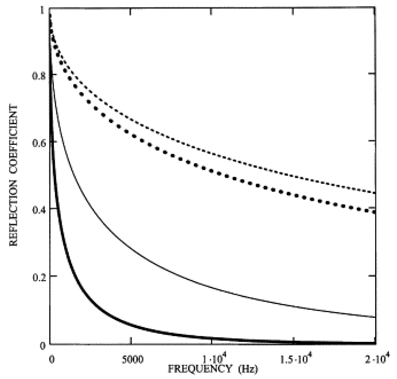
In 2003, Krylov first used the name “acoustic black hole” [13]. The theoretical and numerical work [29] on beams with a one-dimensional acoustic black hole (1D ABH), as shown in Figure 3, was developed. Figure 4 and Figure 5 show the effect of various truncation length x0 and thickness of absorbing film δ on the reflection coefficient of the ABH. First, it can be observed from the behavior of the reflection coefficient for the uncovered wedge (solid curve) that a small truncation can result in a large increase of the refection coefficient. Second, it can be observed that the reflection coefficient increases with the increase of truncation length. Third, damping layers with higher relative stiffness can decrease the reflection coefficient further. Finally, the reflection coefficient decreases with the increase of excitation frequency. These two figures indicate that the presence of thin absorbing layers on the surfaces of ABH wedges can result in very low reflection coefficients of flexural waves from their edges.
A numerical study of beams with a spiral ABH was developed by Jeon et al. [35,36]. The spiral ABH is a compact and curvilinear shape by using an Archimedean spiral with a uniform gap-distance between adjacent baselines of the spiral as shown in Figure 6. Figure 7 shows the driving point mobility of the beam with a 720 mm spiral ABH compared with reference uniform beam (black line). The beam with the ABH is 10% lighter than the reference beam, but it reduces the resonant peak levels to 90% without additional damping. This indicates that the spiral ABH has great potential for vibration damping.
Recently, Zhou and Cheng proposed a numerical and experimental work to develop an ABH that featured a resonant beam damper, as shown in Figure 8 (ABH-RBD) [37]. Figure 9 shows the measured driving and cross point mobility of the host beam with and without ABH-RBD. It can be observed that a significant vibration reduction is obtained with mounting the ABH-RBD. This study shows a great damping treatment of ABH-RBD to control the vibration of the host structure.

3.1.2. Vibration Damping of Plates with ABH

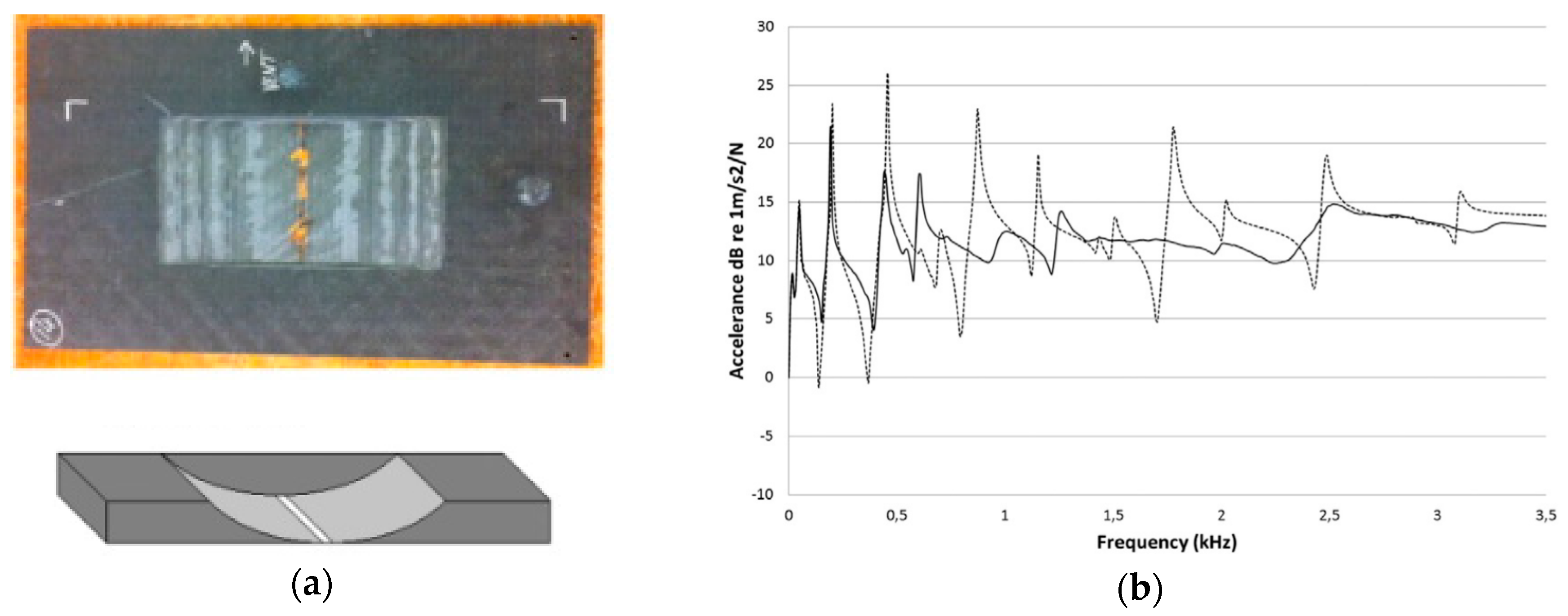
The vibration performance of the plates with various 1D ABH slots was studied by Bowyer [38]. One of the samples is shown in Figure 10a. From the experimental result of this sample, it can be observed that a substantial reduction of acceleration is obtained in comparison with the reference plate. The experimental results of other steel plates and composite plates with various slots also show acceptable damping performance. The composite plates have good damping performance even without the damping layer attached due to the large material loss factor.
Experimental investigation on damping flexural vibrations using two-dimensional acoustic black holes (2D ABHs) was developed by Bowyer et al. [3]. Figure 11 shows the schematics of the experimental samples. The forced excitation was applied to the center of the plate via shaker over a frequency range of 0–9 kHz. The experimental results show that, in comparison with the reference plate, the plate embedded with single 2D ABH with a damping layer provides little damping below 3 kHz. In the region of 3.8–9 kHz, damping varies between 3–8 dB, and maximum damping occurs at 6.6 kHz. Due to the long wave length, the damping performance of the ABH is not evident at low frequency, but it has better damping performance for higher frequencies. It is also indicated by this study that the plates with multiple holes in the current random layout does not significantly improve the damping performance of the 2D ABHs in comparison with the plate with a single 2D ABH.
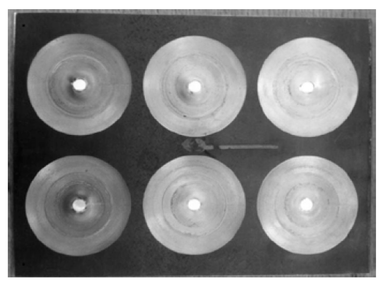
Later, another experimental investigation of damping flexural vibrations in plates was also developed by Bowyer et al. [39]. Figure 12 shows the steel plate containing an array of six 2D ABH. Figure 13 clearly shows that, compared with the reference plate without ABH, the acceleration of the plate with six ABHs attaching damping layers sharply decreases. Additionally, it shows that the minimum frequency of effective damping performance is about 1.5 kHz. These two experimental investigations indicate that ABHs with damping layers can decrease the vibration of plates and the number and configuration of ABHs affect the performance of vibration damping. The increase in the number of ABHs can expand the effective frequency of damping performance of the plate with a 2D ABH and damping layer.
Other shapes of plates with ABH are also studied. Mobilities for a circular plate with a central ABH with a thin damping layer and a constrained layer are studied by O’Boy and Krylov [40]. The point- and cross-mobilities show a suppression of resonant peaks which is up to 17 dB compared with the reference plate. A numerical and experimental study of the acoustic black hole effect for vibration damping in elliptical plates has been studied by Georgiev et al. [41]. Elliptical plates with ABH and without ABH were tested. An elliptical plate with disks of resin placed at the location of the ABHs and an elliptical plate completely covered by resin were also tested. Figure 14 shows velocity fields of plates with ABH (b) and without ABH (a). The excitation force was applied to the left focus whereas the ABH is in the right one. It can be observed that the plate with ABH (b) has a lower amplitude of vibration. Figure 15 shows the point mobility measured at the left focus of the plate. It can be observed that the point mobility of the plate with ABH with the damping material at its location was reduced over 2 kHz.
Not only were plates with ABH with damping material, but also ABH with dynamic vibration absorbers (DVA) were studied by Jia et al., as shown in Figure 16 [42]. It can be observed from the simulation results that there is a reduction of over 10 dB at major response peaks over 1 kHz for the plate with ABH with DVA. This result shows great potential of combining ABHs and DVAs for vibration control.
Since the structures with multiple ABHs have great damping effect for vibration and sound, such structures can be considered as metamaterials [43]. Semperlotti and Zhu developed a meta-structure based on the concept of ABH [44]. This load-bearing thin-wall structure element enables propagation characteristics comparable with resonant metamaterials without the fabrication complexity. The experimental work shows that the ABH treatments can significantly improve the damping effect.
A waveguide is designed to observe travelling waves by Foucaud et al. [45], which is inspired by artificial cochlea. The experimental study (shown in Figure 17) uses a varying width plate immersed in fluid and terminated with an ABH. It shows that an ABH used as an anechoic end improves the quality of measurements and the accuracy of tonotopic maps due to the attenuation of reflected waves.

3.1.3. Vibration Damping of Turbofan Blades with ABH

An experimental work of damping of flexural vibrations in turbofan blades using ABH was studied by Bowyer and Krylov [46]. Figure 18a shows the fan blade profile with a tapered ABH geometry. The experimental setup with four experimental samples are shown in Figure 19. Figure 20 shows the measurement of acceleration for a twisted reference blade (dashed line) compared to a blade with a 1D ABH and damping layer (solid line). It can be observed that the acceleration has about 50% reduction at 60 Hz and 360 Hz. This indicates that the trailing edges of the 1D ABH with appropriate damping layers are efficient in the reduction of airflow-excited vibrations of the fan blades. This study shows the great potential of the ABH in jet engine design to reduce flexural vibration in the blades, thus reducing internal stresses in the blades and increasing their fatigue life cycle.

3.2. Application of ABH to Sound Reduction

An experimental work was developed by Bowyer and Krylov [47]. A 300 × 400 mm × 5-mm thick plate embedded with six 2D ABHs (Figure 21) with damping at the center of each ABH was suspended vertically. The excitation force was applied centrally on the plate. The results compare the sound radiation power level of a plate containing six 2D ABHs with a damping layer with the sound radiation power level of the reference plate, which are shown in Figure 22. Below 1 kHz there is little reduction in the sound power level. Between 1 and 3 kHz, the sound power level is reduced by 10–18 dB in comparison with the reference plate, and the maximum reduction in the sound radiation occurs at 1.6 kHz. Above 3 kHz, almost all responses in sound radiation are absorbed. This indicates that the plate with ABHs having damping layers effectively reduce the sound radiation of the steel plate.
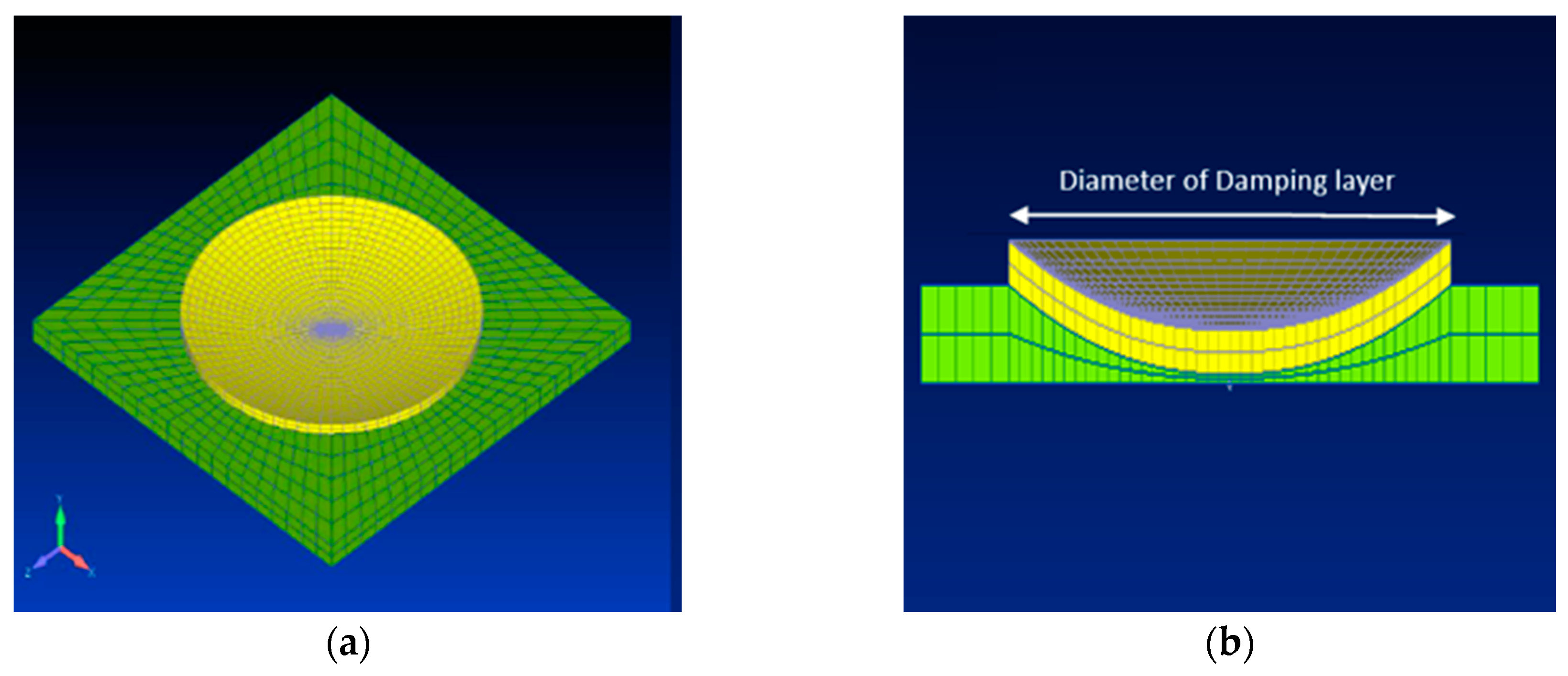
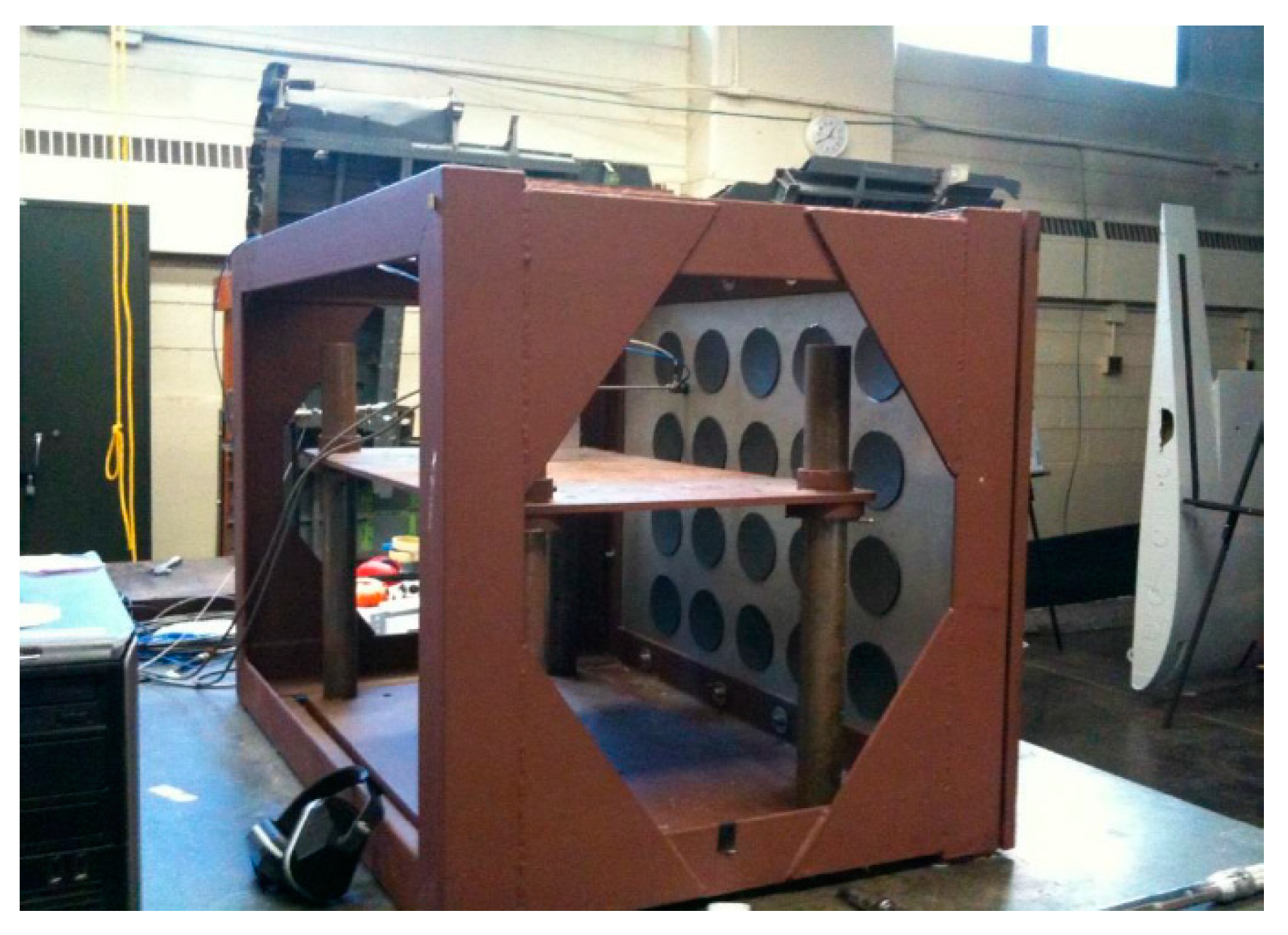
Feurtado and Conlon developed a numerical and experimental investigation of sound power of a plate with an array of ABH [48]. A 4 × 5 array of 10-cm diameter 2D ABHs, which is shown in Figure 23, was machined into a 6.35-mm thick, 61 cm × 91 cm aluminum plate. The ABH with various diameters of damping layers was tested to assess the effects of the amount of damping layer on ABH performance. The experimental setup is shown in Figure 24. The plate was mounted on a frame and excited with band-limited white noise. Figure 25 shows one-third octave band radiated sound power tested by an intensity probe for a uniform plate and ABH plate with various diameters of damping material. It can be observed that an ABH with a damping layer effectively reduced the radiated sound power over 1.5 kHz compared with the reference plate (blue line). It can also be observed that sound radiation of the plate with the diameters of the damping layer of 6.75 cm and 10 cm have almost the same performance, namely higher radiated sound power. The 3.5 cm diameter damping layer shows comparable performance to the larger damping diameters.
A practical experiment is studied by Bowyer and Krylov to investigate the effect of ABH on sound radiation of engine cover [49].The ABH were machined on two plates and then bonded into the engine cover with glue as shown in Figure 26. Figure 27 shows the sound radiation from a reference engine cover (dashed line) in comparison with the engine cover attaching plates with ABH (black line) at 2100 rpm with the bonnet closed. A total average reduction from the reference specimen of 6.5 dB was recorded. This indicates that engine covers with ABHs can decrease the sound radiation from the vehicle engine.
An experimental study on sound absorption in air of ABH based inhomogeneous acoustic waveguides [50] was developed by Azbaid et al. [51,52]. The inner radius of the structures as shown in Figure 28 are built following the linear function (exponent m = 1) and power-law function (exponent m = 2), respectively. Using two microphone transfer function methods, the experiment results show a substantial reduction in the reflection coefficient. The adding of absorbing porous materials results in a further reduction of the reflection coefficient.
A numerical study on Helmholtz resonators (HR) using ABH to enhance the energy absorption performance was developed by Zhou and Semperlotti [53]. The HR cavity shown in Figure 29 is partitioned by a flexible plate-embedded ABH and the numerical results show a great increase in the energy absorption of the HR system.

3.3. Application of ABH to Vibration Energy Harvesting

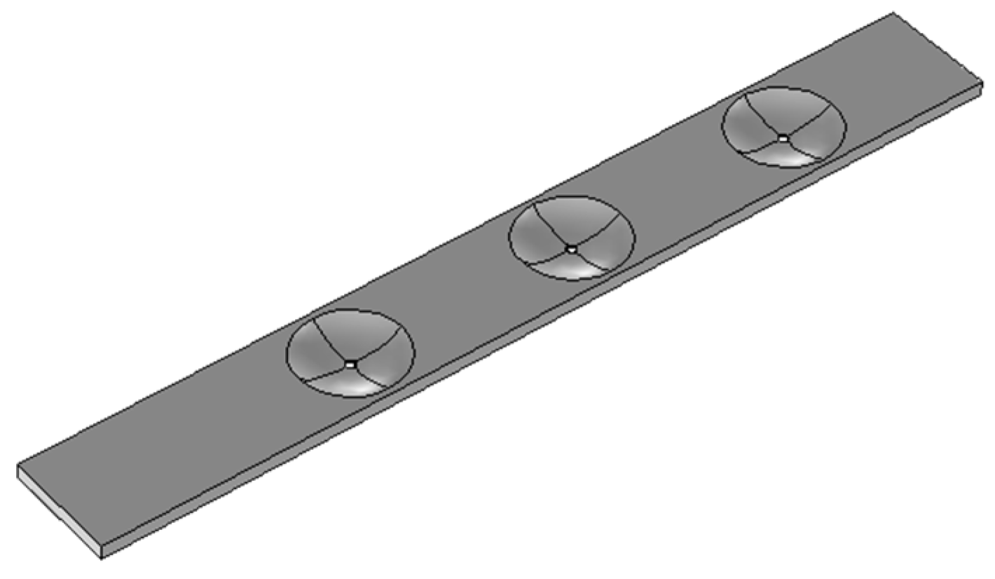
Zhao and Conlon developed a numerical study to investigate the structures tailored with ABHs to enhance vibration energy harvesting under both steady state and transient excitation [10]. Figure 30 shows the schematic of the plate with five equally spaced 1D ABH grooves attached with transducers. The plate is excited on the right side by a 400 N force sweeping from 0 to 10 kHz. The external resistance is 1 Ω. The numerical results of this study show the performance of the energy harvesting under steady state excitation and transient excitation. It can be observed that, by comparing with the flat plate, the normalized energy ratio of the plate with ABH increases drastically up to 80% in the 5–10 kHz frequency band at all the five ABH locations, and it increases most at Location 2. This study shows that the structure with ABH can drastically increase the efficiency of the energy harvesting. Later, another numerical and experimental investigation of a plate with three 2D ABHs (as shown in Figure 31) was also studied by Zhao and Conlon [54]. The ABHs effectively focus broadband energy to the center of the ABH. This also indicates that the focusing ability of the ABH is independent of the spectral and spatial characteristics of the external mechanical load.
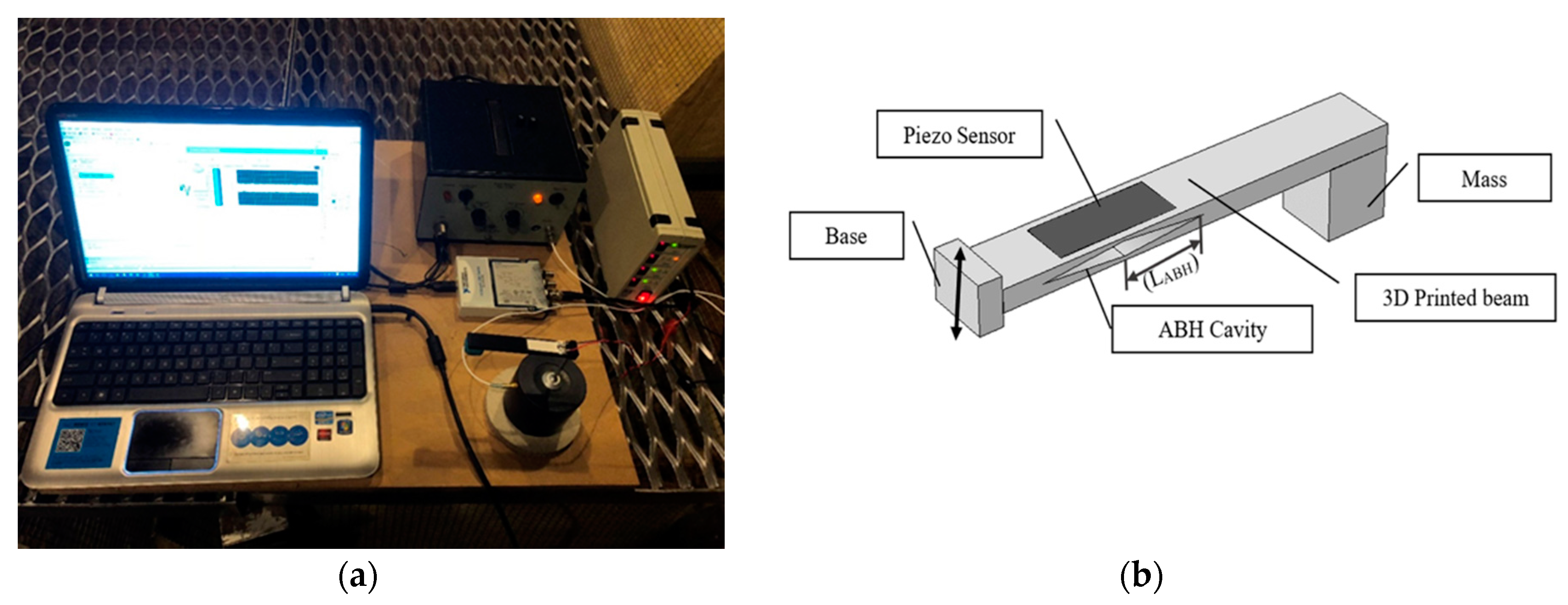
An experimental study on vibration energy harvesting using a cantilever beam with a modified ABH cavity was developed by Zhao and Prasad [8]. The cantilever beam is designed with an ABH cavity near the fixed end due to the presence of higher strain energy. The experimental setup of a cantilever beam with modified ABH cavity attaching a piezo sensor is shown in Figure 32. Figure 33 shows the energy concentration effect of the ABH cavity at 2000 Hz. Figure 34 shows the experimental results of the voltage power spectra. The vertical axis presents the decibel value referring to 1 volt. It can be observed that the beam with ABH cavity (red line) has a higher voltage output level within the frequency range from 900–500 Hz, the voltage output is 10 dB higher than the beam without the ABH (blue line). The increases due to the ABH cavity are substantial, even without considering the neutralization of the piezo material. Embedding a modified ABH cavity uses less piezoelectrical material and decreases the weight of the host structure. Tunability can be achieved by adjusting the length of the ABH cavity. Thus, ABH cavity design into structures has good potential in increasing the energy harvested.
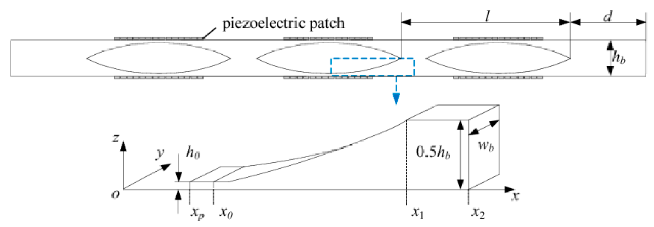
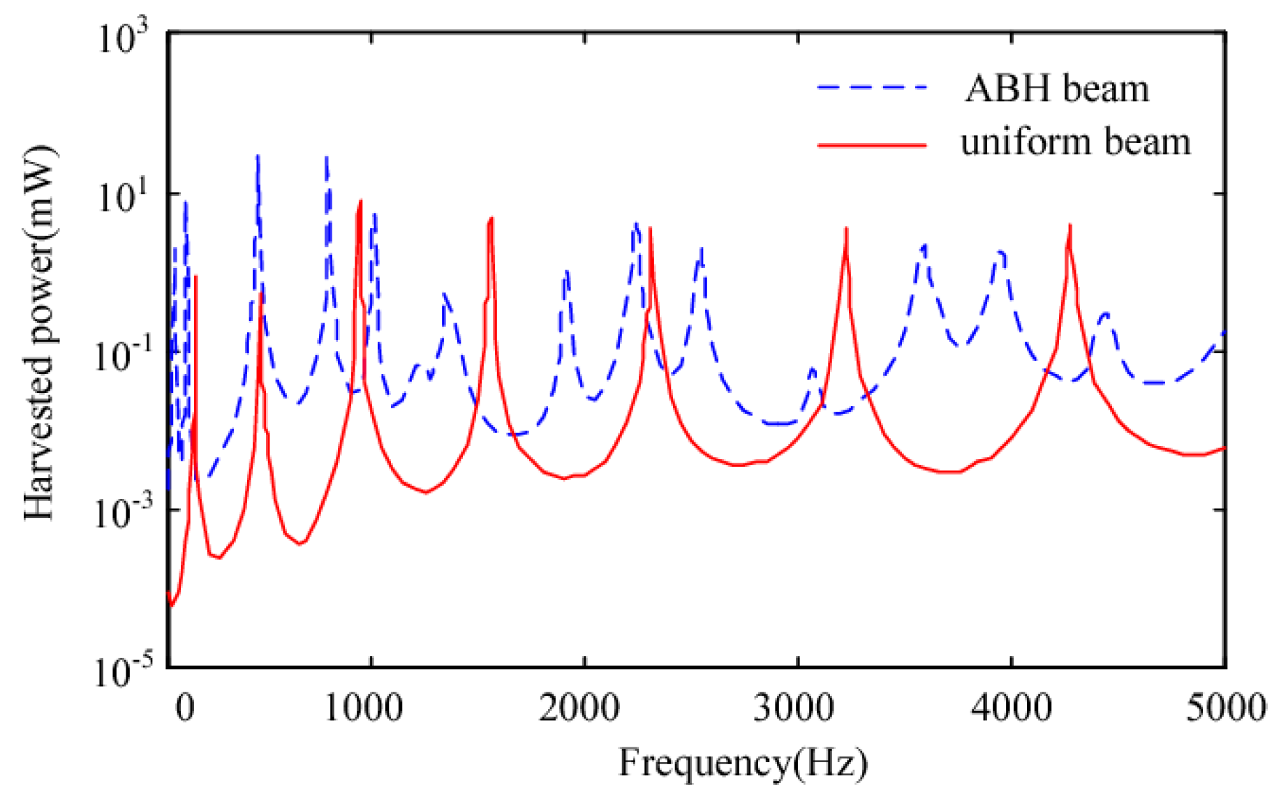
A numerical study on energy harvesting using multiple ABH cavities as shown in Figure 35 was studied by Liang et al. [26]. The size of piezoelectric patches is designed to be relatively smaller than the wavelengths of ABH features, avoiding neutralization of the electric charge. Figure 36 shows the numerical result of power harvested. The results show that the beam with ABH cavities are more effective for vibration energy harvesting than uniform structures.

3.4. Discussion

Applications of ABH for vibration control, sound radiation and vibration energy harvesting are presented. Generally, 1D ABH edges or grooves on beams and multiple 2D ABHs on plates with damping materials or piezo transducers are the major methods for the design of structures to enhance the vibration damping, sound reduction, and energy harvesting. Some specific structures embedding ABHs for practical applications, such as turbo fan blades, engine covers, etc., are also reviewed.

4. Design of Structures Using Acoustic Black Holes

4.1. Design of 1D ABH

The length of the ABH (LABH), the exponent m, and the residual thickness h1 are the three geometrical parameters that affect the shape of 1D ABHs. Exponent m affects the depth of the ABH curve when the length of the ABH and residual thickness are fixed. Figure 37a shows the various shapes of power-law profiles with different values of exponent m. m = 0 means the beam is of uniform thickness (no ABH). LABH affects the length of ABH part when m is fixed as shown in Figure 37b. For 2D ABH, LABH represents the radius of outer circle abstracting the radius of inner hole.
In the study by Krylov, which is mentioned in Section 3.1.1 [29], the concept of “truncation” is applied. For a given value of exponent m, the truncation length is controlled by two variables, the length of the ABH LABH and the residual thickness h1. In this numerical study, it can be observed that when the truncation length is larger than about 0.01 m the reflection coefficient of the beam with ABH (the solid line in Figure 4) increases sharply. This indicates that even a small truncation length results in a large increase in the reflection coefficient, which weakens the ABH effect. Thus, a sharp end of an ABH is critical for structural design. It is noted that a small amount of damping material can effectively restrain the increase of reflection coefficient.
A numerical and experimental study on sound radiation of a beam with a 1D ABH is developed by Li and Ding [55]. In Figure 38, it can be seen that the increase of the truncation thickness results in decrease of radiated sound power in the frequency from 43 to 160 Hz and increase from 626 Hz to 6 kHz. The reason for this phenomenon was discussed and explained. The increase of truncation thickness causes added mass and equivalent stiffness effects, which makes an enhancement of the low frequency bandwidth. On the other hand, an increase of truncation thickness causes an increase of the reflection coefficient and a decrease of the degree of wave concentration in the ABH, therefore weakening noise suppression at high frequencies. This indicates that an optimization of the truncation thickness is required for the best performance of noise reduction.
A wavelet-decomposed energy model is developed and investigated by Tang and Cheng [56]. A new type of beam structure to achieve broad attenuation bands in relatively low frequencies is proposed. The model can be used to predict the frequency bounds of the band gaps. A parametric analysis is also illustrated. The increase of m and decrease of the truncation thickness h0 would decrease the lower band gaps so as to enhance the ABH effect.
A numerical study on the influence of geometrical parameters of ABHs on vibration of cantilever beams was studied by Zhao and Prasad [57]. Figure 39 shows the 3rd mode shape simulation results of the beam without ABH [58] and beams with 1D ABH with various m values. It can be observed that the amplitude of displacement increases at the ABH location (with the increase of m value) and decreases at other locations of nodes.
The numerical study on the sound radiation from vibrating cantilever aluminum beams with various exponent m, which are 10 inches long, 1 inch wide, and 1/8 inch thick, with various shapes of ABHs at the free end, and the residual thickness h1 equal to 1/64 inch is developed by Zhao and Prasad [27]. The results show that, in this group of beams with given residual thickness and length of the ABH, the concentration effect performs better when m is less than 5. However, when m is larger than 5, the ABH loses its concentration effect. Figure 40b shows how the logarithmic ratio of near field sound radiation at the free end and the other three anti-node locations changes with various m values, which essentially shows how the m values affect the concentration effect. This indicates that the m value has a maximum limitation. Another theoretical and numerical study on vibration energy concentration of the 1D ABH was developed by Li and Ding [59]. The length of the edge part with comparatively large deflection deformation Le, as show in Figure 41, was investigated. With the given parameters of the ABH, the results show that more than 80% strain energy and 96% kinetic energy are trapped within a small area (Le) from the wedge tip, which shows the energy concentration effect. For a fixed value of Le, the peak ratio of energy occurs in the range of m from 2.5–3.0 for this case. This study also indicates that the exponent m has an optimum value to provide the best concentration effect.
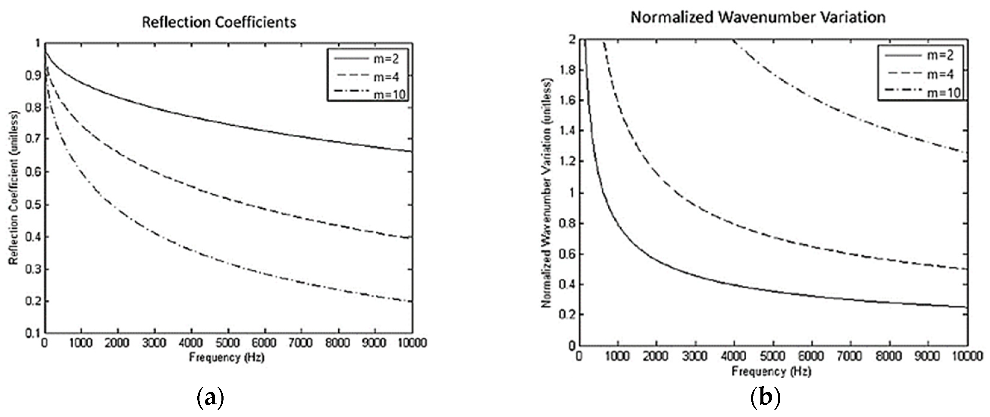
One possible explanation of the phenomenon is that when the m value is larger, the ABH part becomes so thin that the uniform part of the beam and ABH part becomes two isolated vibration systems and it loses the pattern of the response of the beam vibration, the ABH part performs as a untuned dynamic absorber of the uniform part, which can be seen in Figure 39, the beam with m = 10 generated an extra node at the ABH location. A previous study developed by Feurtado and Conlon [9] applied another assumption. In this study, it is shown that the violation of smoothness criterion is a significant design problem for ABHs. Smoothness criterion is an assumption that the change of the local wave number is small enough over distances to make the ABH perform better, which is stated by Mironov [12]. Wave number variation (NWV) is investigated to assess the validity of the smoothness criterion. Equation (17) shows that NWV is a function of frequency and position and need to be much less than 1.
d k ( x ) d x 1 k 2 = ( 1 2 ) ( E ρ ω 2 12 ( 1 υ 2 ) ) 1 / 4 1 h 1 / 2 d h d x 1 ,
where E is the Young’s modulus, ν is the Poisson’s ratio, ρ is the density, h is the varying thickness at the ABH of the beams, and ω is the angular frequency of the flexural wave. According to this theory, an increased m value increases the NWV and the smoothness criterion is violated for a greater range of frequencies. For m = 10, the NWV is above one for the frequency range of study, which is shown in Figure 42. Further work investigates that NWV < 0.4 is a good rule for designing ABHs [60].
In the study of Denis et al. which investigated ABH as a vector for energy transfer from the low frequencies to high frequencies in the framework of nonlinear vibration, a parametric study on a number of beams shown in Figure 43 was developed [61]. Longer additional termination, which means longer LABH, can improve the efficiency of energy transfer. It is also noted that a 2D ABH can present larger LABH with minimal thickness and obtains larger modal density in the low-frequency range.
The effect of the length of ABH is also investigated by Zhao and Prasad [8,27]. For a given beam at a given excitation frequency there are specific optimum values of LABH. The simulation results of total energy at the ABH location of beams with the ABH cavity (shown in Figure 32b) is shown in Figure 44. It is seen that the beam with LABH of 19 mm has maximum energy output. This indicates that the ABH is tunable by changing LABH to obtain a higher concentration of vibration energy [8].
From previous studies in this section, it can be seen that, all the three geometrical parameters need an optimization design to get a best performance on vibration damping and sound reduction. An investigation of the optimization design and position of an embedded 1D ABH is studied by McCormick [62]. This study is on a thin simply-supported beam with a 1D ABH at some position along the beam. The relevant design variables are shown in Figure 45, which are the length of the ABH LABH, the portion of the damped taper Ld, the thickness of the damping layer hd, the drive point location D, and the offset between the center of the beam and the center of the ABH B. The optimization result is shown in Figure 46. Comparing with the uniform beam, the simple damped beam can decrease the surface-averaged velocity, but increases the mass by 5%. The optimized design can decrease the total mass of the beam by 15% and decreases the total surface-averaged velocity response by 12 dB, which has more reduction than a simple damped beam. The aim of the study is to figure out the ABH design that minimizes the total mass of the beam and, at the same time, minimizes the total surface-averaged velocity response. This benefits the design of ABHs for vibration reduction without adding mass.
As shown in the studies on vibration of beams and plates with ABH in Section 3.1, there is a minimum effective frequency, below which the ABH damping performance is not evident. A numerical and experimental study on the investigation of disappearance of the ABH effect is presented by Tang and Cheng [63]. It shows that cut-on frequency bands close to the low-order local resonant frequencies of the beam exist and the ABH effect failure in these frequency bands. The failure frequencies of the beam are delimited by the excitation point in order to avoid the phenomenon in the structural design.

4.2. Design of a 2D ABH

For a 2D ABH, it is to be noted that, besides geometrical parameters, the spatial layout of the ABH, the material of the host structure and damping material, the diameter of center hole, and the number of ABH also affect the performance of the ABH.
A numerical analysis of flexural ray trajectories in 2D ABH is developed by Huang et al. [32]. Figure 47 shows that for a given value of exponent m, the 2D ABH with thinner residual thickness (h1 = 0.0002 m) absorbs more propagation energy than the one with residual thickness of h1 = 0.001 m. In this study, the results also show the ratio of the rays converging to the center is 99.69% in the ideal ABH. The wave focalization can be enhanced with a larger m and a small h1.
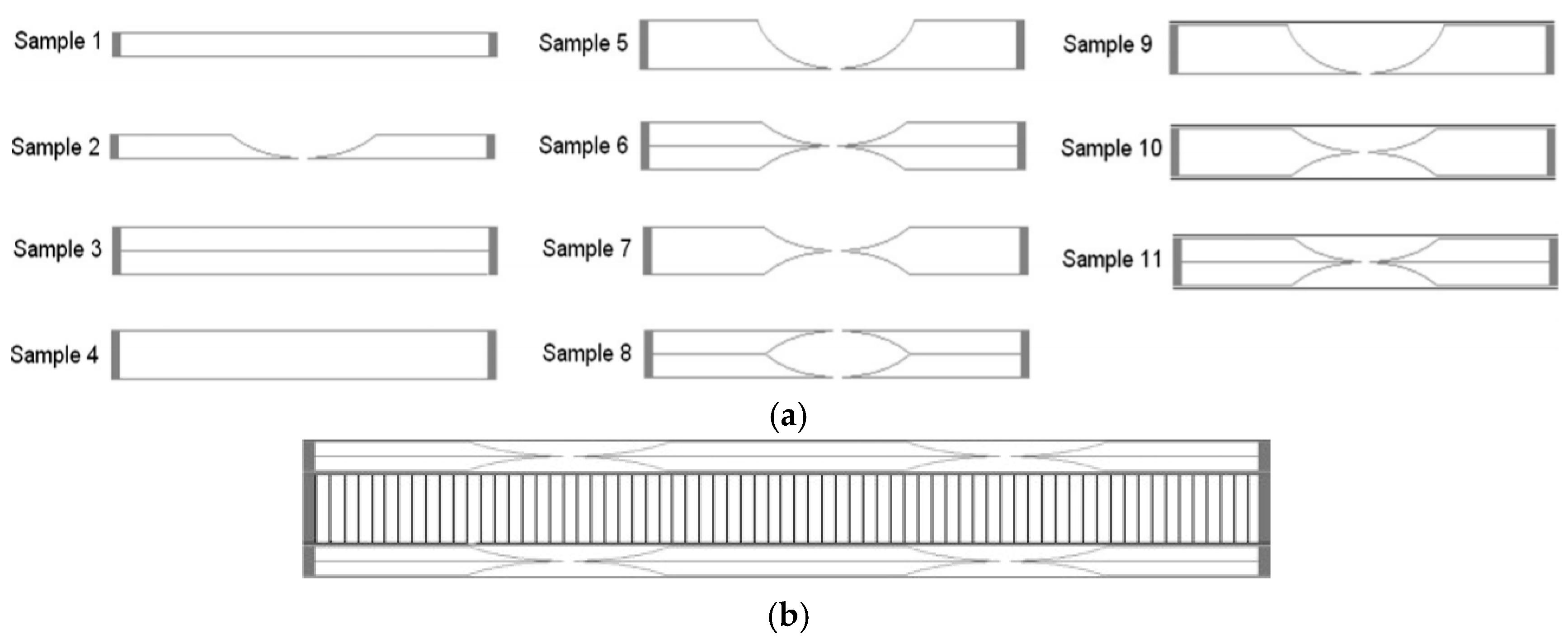
A study on various layout of ABH on glass fiber composite plates with 1D and 2D ABH was studied by Bowyer and Krylov [16]. In this study, the glass fiber composite honeycomb sandwich panels with two 2D ABHs with various configurations (shown in Figure 48a) are investigated and the experimental results of acceleration are compared with a reference sandwich panel without ABH plates. The results show that theoretically the structure in Figure 48b should be the optimum layout to perform with the best vibration damping.
Due to the limitation of manufacturing, the ABH may not be perfect. A study on the wave energy focalization in a plate with imperfect 2D ABH is developed by Huang et al. [64]. The imperfect 2D ABH uses a polynomial profile instead of a power-law profile. The results still show drastic increases in energy density around the tapered area. Chong also indicates that the smooth and stepped ABH beams are slightly different [22]. Denis et al. also find that the controlled imperfection of the tip of the 1D ABH causes a decrease of the reflection coefficient, which indicates that imperfect extremities are not detrimental to the performance of the ABH effect [65]. These two studies lower the stringent requirement of the ideal power-law thickness variation of ABH.
A numerical study on the influence of number of ABHs on a plate in vibration is carried out by Conlon et al. [66,67]. The space averaged acceleration and total radiated sound power results for the 5 × 5 ABH (shown in Figure 49a) and uniform plates are compared in Figure 50. This shows that the plate with the ABH array has very effective results on vibration and noise reduction. Another comparison of total radiated sound power response of ABH panel between the panel with a 5 × 5 ABH array (Figure 49a) and the panel with 13 ABHs (Figure 49b) is shown in Figure 51. It can be seen that for higher frequencies (over 5 kHz) increasing of the number of ABHs results in more sound reduction, but in lower frequency this effect can only be observed in a few areas. This type of ABH array was also applied on the phononic crystals (PC) by Zhu and Semperlotti [68] to investigate peculiar dispersion characteristics.

4.3. Design of Damping Layer

The study Feurtado and Conlon [48] mentioned in Section 3.2 indicates that the radius of the damping layer has an optimum value. When the diameter is larger than the optimum value, the damping effect increases slightly. A time domain experimental study based on a laser visualization system is developed by Ji et al. [31]. The wave propagation and attenuation in a plate-embedded 1D ABH is investigated. It is also noted that there exists an optimal thickness for the damping layer. Krylov indicate that the damping material with higher material loss factor makes the damping effect of the ABH have better performance [29]. Denis et al. indicate that a good compromise has been found by using a long additional termination with a moderate length of the damping layer in the framework of nonlinear vibration, which can develop into a turbulent regime [61]. An optimization study was developed by Lee et al. [69] and indicates that the damping performance can be enhanced by treating the tip with an appropriate size of damping layer. Another study developed by Tang et al. [34] shows that the stiffness of the damping layer plays is more critical than mass for a better damping effect but, meanwhile, the effect of the added mass still needs to be accurately designed especially when the thickness of damping is considerable to the tip of the ABH wedge.

4.4. Studies on 3D-Printed Structures with ABH

Due to the limitation of traditional manufacturing methods, a power-law curve is difficult to manufacture. Bowyer and Krylov indicate that milling is not a practical way to machine structures with 2D ABH and suggest that 3D printing technology can be applied to produce these structures [23]. Due to the well-known advantages of 3D printing [70], vibration and sound radiation of 3D-printed structures are investigated by researchers. Zhou et al. developed a numerical study to investigate the dynamic and static properties of 3D-printed double-layered compound structures with ABHs [24]. Due to small residual thickness of the ABH profile, the structure with ABHs has low local stiffness and high stress concentration. The double-layered compound structure shows good damping performance and also significantly improves the static properties in structural stiffness and strength. Zhao and Prasad developed an experimental case study of vibration energy harvesting of a 3D-printed beam with a modified ABH cavity [8]. Liang et al. developed a numerical simulation for vibration energy harvesting of a 3D-printed beam with multiple ABH cavities [26]. Chong et al. numerically and experimentally studied the dynamic responses of 3D-printed beam with damped ABH grooves [22]. Rothe et al. investigated the dynamic behavior of the 3D-printed beams using a 3D- hexahedron finite element and an isotropic linear elastic homogenized material model [25]. A cantilever beam is embedded with the ABH at its free ends and fully fills the ABH area with flexible thermoplastic polyurethane (TPU) to make the overall thickness uniform. In comparison with the uniform beam, the beam-embedded ABH with TPU shows good damping performance.

5. Concluding Remarks

This review has presented the recent theoretical and numerical studies on ABH. Applications of ABH on beam- and plate-type structures have been demonstrated. It is shown that the use of ABH in structural design is effective in controlling vibration and noise without adding additional mass. This is particularly important for the design of lightweight structures, such as aircraft panels. ABH has also shown good promise in vibration energy harvesting, however, its practical application is still under research.
The current studies show that for 1D ABH, the geometric parameters are critical for the ABH effect. For 2D ABH, besides geometrical parameters, additional variables, such as the diameter of the center hole, the spatial layout of ABH array, and the number of ABHs, influence the performance of the ABH effect. Additionally, the material of the host structure and damping material are important for both 1D and 2D ABH. Optimization of the geometric parameters can significantly improve the damping effect of ABH. The number of ABHs and their spatial layout can expand the effective frequency range of ABH. A higher loss factor for both the host structure and damping layer can further improve the damping effect of ABH using less additive damping. However, there is a need for research efforts to further understand the interdependence of various geometrical parameters so that structural optimization studies can be carried out in designing structures with ABHs for better performance in vibration and noise control.
3D printing technology makes the manufacturing of more complex structures possible, and it is being applied in structures with ABH features. Further studies are required to apply ABH widely to real-life structures and carry out the application for more complex structures. Thus, it is observed from this review of various studies that the use of ABH in structural design for vibration and noise control is significantly effective and has great potential for research and industrial applications.

Funding

This research received no external funding.

Acknowledgments

The first author thanks the support from Department of Mechanical Engineering of Stevens Institute of Technology.

Conflicts of Interest

The authors declare no conflict of interest.

References

  1. Rao, M.D. Recent applications of viscoelastic damping for noise control in automobiles and commercial airplanes. J. Sound Vib. 2003, 262, 457–474. [Google Scholar] [CrossRef]
  2. Denis, V. Vibration Damping in Beams Using the Acoustic Black Hole Effect. Ph.D. Thesis, Universit´e du Maine, Le Mans, France, 2014. [Google Scholar]
  3. Bowyer, E.P.; O’Boy, D.J.; Krylov, V.V.; Gautier, F. Experimental investigation of damping flexural vibrations using two-dimensional Acoustic ‘Black Holes’. In Proceedings of the International Conference on Noise and Vibration Engineering (ISMA 2010), Leuven, Belgium, 20–22 September 2010. [Google Scholar]
  4. Nishimura, I.; Kobori, T.; Sakamoto, M.; Koshika, N.; Sasaki, K.; Ohrui, S. Active tuned mass damper. Smart Mater. Struct. 1992, 1, 306. [Google Scholar] [CrossRef]
  5. Mead, D.J. Passive Vibration Control; Wiley: Chichester, UK, 1999. [Google Scholar]
  6. Li, H.; Tian, C.; Deng, Z. Energy harvesting from low frequency applications using piezoelectric materials. Appl. Phys. Rev. 2014, 1, 041301. [Google Scholar] [CrossRef]
  7. Sojan, S.; Kulkarni, R. A Comprehensive Review of energy harvesting techniques and its potential applications. Int. J. Comput. Appl. 2016, 139, 14–19. [Google Scholar] [CrossRef]
  8. Zhao, C.; Prasad, M.G. Studies on vibration energy harvesting using a cantilever beam with a modified Acoustic Black Hole cavity. In Proceedings of the Inter-Noise 2018, Chicago, IL, USA, 26–29 August 2018. [Google Scholar]
  9. Feurtado, P.A.; Conlon, S.C.; Semperlotti, F.A. Normalized wave number variation parameter for Acoustic Black Hole design. J. Acoust. Soc. Am. 2014, 136, 148–152. [Google Scholar] [CrossRef] [PubMed]
  10. Zhao, L.; Conlon, S.C.; Semperlotti, F. Broadband energy harvesting using Acoustic Black Hole structural tailoring. Smart Mater. Struct. 2014, 23, 065021. [Google Scholar] [CrossRef]
  11. Pekeris, C.L. Theory of propagation of sound in a half-space of variable sound velocity under conditions of formation of a shadow zone. J. Acoust. Soc. Am. 1946, 18, 295–315. [Google Scholar] [CrossRef]
  12. Mironov, M.A. Propagation of a flexural wave in a plate whose thickness decreases smoothly to zero in a finite interval. Sov. Phys. Acoust. 1988, 34, 318–319. [Google Scholar]
  13. Krylov, V.V.; Bowyer, E.P. Acoustic Black Holes: A new approach to vibration damping in light-weight structures. Proc. Inst. Acoust. 2003, 35, 184–191. [Google Scholar]
  14. Krylov, V.V.; Shuvalov, A.L. Propagation of localised flexural vibrations along plate edges described by a power law. Proc. Inst. Acoust. 2000, 22, 263–270. [Google Scholar]
  15. Krylov, V.V. Acoustic Black Holes and their applications for vibration damping and sound absorption. In Proceedings of the International Conference on Noise and Vibration Engineering (ISMA 2012), Leuven, Belgium, 17–19 September 2012; pp. 933–944. [Google Scholar]
  16. Bowyer, E.P.; Krylov, V.V. Experimental investigation of damping flexural vibrations in glass fiber composite plates containing one- and two-dimensional Acoustic Black Holes. Compos. Struct. 2014, 107, 406–415. [Google Scholar] [CrossRef]
  17. Krylov, V.V. Acoustic Black Holes: Recent developments in the theory and applications. IEEE Trans. Ultrason. Ferroelectr. Freq. Control 2014, 61, 1296–1306. [Google Scholar] [CrossRef] [PubMed]
  18. Conlon, S.C.; Fahnline, J.; Semperlotti, F. Numerical analysis of the vibroacoustic properties of plates with embedded grids of Acoustic Black Holes. J. Acoust. Soc. Am. 2015, 137, 447. [Google Scholar] [CrossRef] [PubMed]
  19. Conlon, S.C.; Semperlotti, F. Passive control of vibration and sound transmission for vehicle structures via embedded Acoustic Black Holes. In Proceedings of the Noise-Con 2013, Denver, CO, USA, 26–28 August 2013. [Google Scholar]
  20. Conlon, S.C.; Feurtado, P.A. Progressive phase trends in plates with embedded Acoustic Black Holes. J. Acoust. Soc. Am. 2018, 143, 921. [Google Scholar] [CrossRef] [PubMed]
  21. Ji, H.; Huang, W.; Qiu, J.; Cheng, L. Mechanics problems in application of Acoustic Black Hole structures. Adv. Mech. 2017, 47, 201710. [Google Scholar]
  22. Chong, B.M.P.; Tan, L.B.; Lim, K.M.; Lee, H.P. A review on Acoustic Black-Holes (ABH) and the experimental and numerical study of ABH-featured 3D printed beams. Int. J. Appl. Mech. 2017, 9, 1750078. [Google Scholar] [CrossRef]
  23. Bowyer, E.P.; Krylov, V.V. Acoustic Black Hole manufacturing for practical applications and the effect of geomatical and material imperfections. In Proceedings of the Inter-Noise 2016, Hamburg, Germany, 21–24 August 2016. [Google Scholar]
  24. Zhou, T.; Tang, L.; Ji, H.; Qiu, J.; Cheng, L. Dynamic and static properties of double-layered compound Acoustic Black Hole structures. Int. J. Appl. Mech. 2017, 9, 1750074. [Google Scholar] [CrossRef]
  25. Rothe, S.; Blech, C.; Watschke, H.; Vietor, T.; Langer, S.C. Numerical modelling of additively manufactured Acoustic Black Holes. In Proceedings of the Inter-Noise 2018, Chicago, IL, USA, 26–29 August 2018. [Google Scholar]
  26. Liang, Y.; Ji, H.; Qiu, J.; Cheng, L.; Wu, Y.; Zhang, C. Enhancement of piezoelectric energy harvesting using ABH structural tailoring. In Proceedings of the 2018 IEEE/ASME International Conference on Advanced Intelligent Mechatronics (AIM), Auckland, New Zealand, 9–12 July 2018. [Google Scholar]
  27. Zhao, C.; Prasad, M.G. Studies on influence of geometrical parameters of an Acoustic Black Hole. In Proceedings of the Noise-Con 2017, Grand Rapids, MI, USA, 12–14 June 2017. [Google Scholar]
  28. O’Boy, D.J.; Krylov, V.V.; Kralovic, V. Damping of flexural vibrations in rectangular plates using the Acoustic Black Hole effect. J. Sound Vib. 2010, 329, 4672–4688. [Google Scholar] [CrossRef]
  29. Krylov, V.V.; Tilman, F.J.B.S. Acoustic ‘Black Holes’ for flexural waves as effective vibration dampers. J. Sound Vib. 2004, 274, 605–619. [Google Scholar] [CrossRef]
  30. Zhao, L. Passive vibration control based on embedded Acoustic Black Holes. J. Vib. Acoust. 2016, 138, 041002. [Google Scholar] [CrossRef]
  31. Ji, H.; Luo, J.; Qiu, J.; Cheng, L. Investigations on flexural wave propagation and attenuation in a modified one-dimensional Acoustic Black Hole using a laser excitation technique. Mech. Syst. Signal Process. 2018, 104, 19–35. [Google Scholar] [CrossRef]
  32. Huang, W.; Ji, H.; Qiu, J.; Cheng, L. Analysis of ray trajectories of flexural waves propagation over generalized Acoustic Black Hole indentations. J. Sound Vib. 2018, 417, 216–226. [Google Scholar] [CrossRef]
  33. O’Boy, D.J.; Bowyer, E.P.; Krylov, V.V. Damping of flexural vibrations in thin plates using one and two dimensional Acoustic Black Hole Effect. In Proceedings of the 10th International Conference on Recent Advances in Structural Dynamics (RASD 2010), Southampton, UK, 12–14 July 2010. [Google Scholar]
  34. Tang, L.; Cheng, L.; Ji, H.; Qiu, J. Characterization of Acoustic Black Hole effect using a one-dimensional fully-coupled and wavelet-decomposed semi-analytical model. J. Sound Vib. 2016, 374, 172–184. [Google Scholar] [CrossRef]
  35. Jeon, W. Vibration damping using a spiral Acoustic Black Hole. In Proceedings of the Inter-Noise 2016, Hamburg, Germany, 21–24 August 2016. [Google Scholar]
  36. Lee, J.Y.; Jeon, W. Vibration damping using a spiral Acoustic Black Hole. J. Acoust. Soc. Am. 2017, 141, 1437. [Google Scholar] [CrossRef] [PubMed]
  37. Zhou, T.; Cheng, L. A resonant beam damper tailored with Acoustic Black Hole features for broadband vibration reduction. J. Sound Vib. 2018, 430, 174–184. [Google Scholar] [CrossRef]
  38. Bowyer, E.P.; Krylov, V.V. Slots of power-law profile as Acoustic Black Holes for flexural waves in metallic and composite plates. Structures 2016, 6, 48–58. [Google Scholar] [CrossRef]
  39. Bowyer, E.P.; O’Boy, D.J.; Krylov, V.V.; Gautier, F. Experimental investigation of damping flexural vibrations in plates containing tapered indentations of power-law profile. Appli. Acoust. 2013, 74, 553–560. [Google Scholar] [CrossRef]
  40. O’Boy, D.J.; Krylov, V.V. Damping of flexural vibrations in circular plates with tapered central holes. J. Sound Vib. 2011, 330, 2220–2236. [Google Scholar] [CrossRef]
  41. Georgiev, V.B.; Cuenca, J.; Gautier, F.; Simon, L.; Krylov, V.V. Damping of structural vibrations in beams and elliptical plates using the Acoustic Black Hole effect. J. Sound Vib. 2011, 330, 2497–2508. [Google Scholar] [CrossRef]
  42. Jia, X.; Du, Y.; Zhao, K. Vibration Control of variable thickness plates with embedded Acoustic Black Holes and dynamic vibration absorbers. In Proceedings of the ASME 2015 Noise Control and Acoustics Division Conference, San Francisco, CA, USA, 9–12 August 2015. [Google Scholar]
  43. Krylov, V.V. Acoustic black holes as elements of metamaterials. In Proceedings of the IOP Physical Acoustics Group Tutorial Day, Loughborough, UK, 17 September 2015. [Google Scholar]
  44. Semperlotti, F.; Zhu, H. Acoustic meta-structures based on periodic Acoustic Black Holes. J. Acoust. Soc. Am. 2015, 137, 2265. [Google Scholar] [CrossRef]
  45. Foucaud, S.; Michon, G.; Gourinat, Y.; Pelat, A.; Gautier, F. Artificial Cochlea and Acoustic Black Hole travelling waves observation: Model and experimental results. J. Sound Vib. 2014, 333, 3428–3439. [Google Scholar] [CrossRef]
  46. Bowyer, E.P.; Krylov, V.V. Damping of flexural vibrations in turbofan blades using the Acoustic Black Hole effect. Appl. Acoust. 2014, 76, 359–365. [Google Scholar] [CrossRef]
  47. Bowyer, E.P.; Krylov, V.V. Sound Radiation of rectangular plates containing tapered indentations of power-law profile. In Proceedings of the 164th Meeting of the Acoustical Society of America, Kansas City, MO, USA, 22–26 October 2012. [Google Scholar]
  48. Feurtado, P.A.; Conlon, S.C. Experimental analysis of vibration and radiated sound power reduction using an array of Acoustic Black Holes. In Proceedings of the Inter-Noise 2015, San Francisco, CA, USA, 9–12 August 2015. [Google Scholar]
  49. Bowyer, E.P.; Krylov, V.V. A review of experimental investigations into the Acoustic Black Hole effect and its applications for reduction of flexural vibrations and structure-borne sound. In Proceedings of the Inter-Noise 2015, The 44th International Congress and Exposition on Noise Control Engineering, San Francisco, CA, USA, 9–12 August 2015. [Google Scholar]
  50. Mironov, M.A.; Pislyakov, V.V. One-dimensional acoustic waves in retarding structures with propagation velocity tending to zero. Acoust. Phys. 2002, 48, 347–352. [Google Scholar] [CrossRef]
  51. Azbaid, E.; Krylov, V.V.; O’Boy, D.J. Experimental investigation of the Acoustic Black Hole for sound absorption in air. In Proceedings of the 22nd International Congress on Sound and Vibration, Florence, Italy, 12–16 July 2015. [Google Scholar]
  52. Azbaid, E.; Krylov, V.; O’Boy, D.J. Investigation of the Acoustic Black Hole termination for sound waves propagating in cylindrical waveguides. In Proceedings of the Inter-Noise 2015, San Francisco, CA, USA, 9–12 August 2015. [Google Scholar]
  53. Zhou, X.; Semperlotti, F. The energy absorption properties of Helmholtz resonators enhanced by Acoustic Black Holes. In Proceedings of the Inter-Noise 2016, Hamburg, Germany, 21–24 August 2016. [Google Scholar]
  54. Zhao, L.; Conlon, S.C.; Semperlotti, F. An experimental study of vibration based energy harvesting in dynamically tailored structures with embedded Acoustic Black Holes. Smart Mater. Struct. 2015, 24, 065039. [Google Scholar] [CrossRef]
  55. Li, X.; Ding, Q. Sound radiation of a beam with a wedge-shaped edge embedding Acoustic Black Hole feature. J. Sound Vib. 2019, 439, 287–299. [Google Scholar] [CrossRef]
  56. Tang, L.; Cheng, L. Broadband locally resonant band gaps in periodic beam structures with embedded Acoustic Black Holes. J. Appl. Phys. 2017, 121, 194901. [Google Scholar] [CrossRef]
  57. Zhao, C.; Prasad, M.G. Studies on sound radiation from beam with Acoustic Black Hole. In Proceedings of the Noise-Con 2016, Providence, RI, USA, 13–15 June 2016. [Google Scholar]
  58. Mustakerov, I.; Borissova, D. Multi-criteria model for optimal number and placement of sensors for structural health monitoring: lexicographic method implementation. Adv. Model. Optim. 2014, 16, 103–112. [Google Scholar]
  59. Li, X.; Ding, Q. Analysis on vibration energy concentration of the one-dimensional wedges-shaped Acoustic Black Hole structure. J. Intell. Mater. Syst. Struct. 2018, 29, 2137–2148. [Google Scholar] [CrossRef]
  60. Feurtado, P.A.; Conlon, S.C. Investigation of boundary-taper reflection for Acoustic Black Hole design. Noise Control Eng. J. 2015, 63, 460–466. [Google Scholar] [CrossRef]
  61. Denis, V.; Pelat, A.; Touzé, C.; Gautier, F. Improvement of the Acoustic Black Hole effect by using energy transfer due to geometric nonlinearity. Int. J. Non-Linear Mech. 2017, 94, 134–145. [Google Scholar] [CrossRef]
  62. McCormick, C.A.; Shepherd, M.R. Optimal design and position of an embedded one-dimensional Acoustic Black Hole. In Proceedings of the Inter-Noise 2018, Chicago, IL, USA, 26–29 August 2018. [Google Scholar]
  63. Tang, L.; Cheng, L. Loss of Acoustic Black Hole effect in a structure of finite size. Appl. Phys. Lett. 2016, 109, 014102. [Google Scholar] [CrossRef]
  64. Huang, W.; Ji, H.; Qiu, J.; Cheng, L. Wave energy focalization in a plate with imperfect two-dimensional Acoustic Black Hole indentation. J. Vib. Acoust. 2016, 138, 061004. [Google Scholar] [CrossRef]
  65. Denis, V.; Pelat, A.; Gautier, F. Scattering effects induced by imperfections on an Acoustic Black Hole placed at a structural waveguide termination. J. Sound Vib. 2016, 362, 56–71. [Google Scholar] [CrossRef]
  66. Conlon, S.C.; Fahnline, J.B.; Shepherd, M.R.; Feurtado, P.A. Vibration control using grids of Acoustic Black Holes: How many is enough? In Proceedings of the Inter-Noise 2015, San Francisco, CA, USA, 9–12 August 2015. [Google Scholar]
  67. Conlon, S.C.; Fahnline, J.B.; Semperlotti, F.; Feurtado, P.A. Enhancing the low frequency vibration reduction performance of plates with embedded Acoustic Black Holes. In Proceedings of the Inter-Noise 2014, Melbourne, Australia, 16–19 November 2014. [Google Scholar]
  68. Zhu, H.; Semperlotti, F. Phononic thin plates with embedded Acoustic Black Holes. Phys. Rev. B 2015, 91, 104304. [Google Scholar] [CrossRef]
  69. Lee, J.; Jeon, W. An optimal design of 1D Acoustic Black Hole with damping layer for plate geometry. In Proceedings of the 23rd International Congress of Sound and Vibration, Athens, Greece, 10–14 July 2016; pp. 99–104. [Google Scholar]
  70. Kamran, M.; Saxena, A.A. Comprehensive study on 3D printing technology. MIT Int. J. Mech. Eng. 2016, 6, 63–69. [Google Scholar]
Figure 1. ABH concentration effect, the amplitude of the incident wave increases significantly when propagating to the end of the ABH wedge.
Acoustics 01 00014 g001
Figure 2. Schematic of a 1D ABH [27].
Acoustics 01 00014 g002
Figure 3. Truncated quadratic wedges covered by thin damping layers. x0 is the truncation length. Reprinted with permission from [29]. Copyright Elsevier, 2004.
Acoustics 01 00014 g003
Figure 4. Reflection coefficient for the wedge covered by a thick absorbing film. The solid curve corresponds to an uncovered wedge, and dotted and dashed curves correspond to wedges covered by thin absorbing films with the values of relative stiffness E2/E1 = 2/30 and E2/E1 = 2/3, respectively; the film material loss factor ν is 0.2, and the film thickness δ is 5 μm. Reprinted with permission from [29]. Copyright Elsevier, 2004.
Acoustics 01 00014 g004
Figure 5. Frequency dependence of the reflection coefficient R: x0 = 1.5 and 2.5 cm (thicker and thinner curves, respectively); solid and dotted curves correspond to wedges with absorbing films and to uncovered wedges; the film material loss factor ν is 0.2, and the film thickness δ is 5 μm. Reprinted with permission from [29]. Copyright Elsevier, 2004.
Acoustics 01 00014 g005
Figure 6. Shape of the beam with a spiral ABH. The length of the ABH is 720 mm. Reprinted with permission from [36]. Copyright Acoustic Society of America, 2017.
Acoustics 01 00014 g006
Figure 7. Driving point mobility of the beam with a 720 mm spiral ABH (grey line) and the reference uniform beam (black line). Reprinted with permission from [36]. Copyright Acoustic Society of America, 2017.
Acoustics 01 00014 g007
Figure 8. Schematics of the host beam with an ABH-RBD. Reprinted with permission from [37]. Copyright Elsevier, 2018.
Acoustics 01 00014 g008
Figure 9. Measured (a) driving and (b) cross-point mobility of the primary host beam with and without ABH-RBD. Reprinted with permission from [37]. Copyright Elsevier, 2018.
Acoustics 01 00014 g009
Figure 10. (a) Carbon fiber composite sample and longitudinal cross-section of the sample; and (b) Acceleration for the plate with ABH slot (solid line) and reference plate (dashed line). Reprinted from [38] under a CC BY 4.0 license. Copyright Bowyer, E.P. and Krylov, V.V., 2016.
Acoustics 01 00014 g010
Figure 11. (a) A singular 2D ABH with a center hole, and (b) three 2D ABH with central holes. Adapted from [3] under a CC BY 3.0 license. Copyright Bowyer, E.P. and Krylov, V.V., 2010.
Acoustics 01 00014 g011
Figure 12. Manufactured steel plate containing an array of six 2D ABHs. Reprinted with permission from [39]. Copyright Elsevier, 2013.
Acoustics 01 00014 g012
Figure 13. Measured acceleration for a plate containing six 2D ABHs with 14 mm central holes and additional damping layers (solid line) and a reference plate (dashed line). Reprinted with permission from [39]. Copyright Elsevier, 2013.
Acoustics 01 00014 g013
Figure 14. Velocity fields of an elliptical plate (a) without ABH at 8671 Hz, and (b) with ABH at 8117 Hz. Reprinted with permission from [41]. Copyright Elsevier, 2011.
Acoustics 01 00014 g014
Figure 15. Measured point mobilities of the elliptical plate. The black line shows the plate with ABH by attaching damping material at its location, the dashed line shows the plate without ABH by attaching damping at the same location, and the green line shows the plate without ABH by covering the damping material over the whole plate. Reprinted with permission from [41]. Copyright Elsevier, 2011.
Acoustics 01 00014 g015
Figure 16. Cross-section of the plate structure considered in the FE model and the experiments: (a) a top-view of plate structure with two ABHs, (b) a plate embedded with ABH and damping layer, and (c) a plate embedded with ABH and DVA. Adapted with permission from [42]. Copyright American Society of Mechanical Engineers, 2015.
Acoustics 01 00014 g016
Figure 17. The photo for the assembled experimental setup. Reprinted with permission from [45]. Copyright Elsevier, 2014.
Acoustics 01 00014 g017
Figure 18. (a) Fan blade profile with tapered ABH geometry. (b) Experimental setup. Reprinted from [46] under a CC BY 3.0 license. Copyright Bowyer, E.P. and Krylov, V.V., 2014.
Acoustics 01 00014 g018
Figure 19. Experimental setup of closed-circuit wind tunnel and samples of the test. Experimental samples: Flow visualization diagram for: (a) reference fan blade, (b) fan blade with a power-law wedge, (c) fan blade having a power-law wedge with a single damping layer, and (d) fan blade having a power-law wedge with a shaped damping layer. Reprinted from [46] under a CC BY 3.0 license. Copyright Bowyer, E.P. and Krylov, V.V., 2014.
Acoustics 01 00014 g019
Figure 20. Acceleration for a twisted reference blade (dashed line) compared to a twisted blade with a 1D ABH and damping layer (solid line). Reprinted from [46] under a CC BY 3.0 license. Copyright Bowyer, E.P. and Krylov, V.V., 2014.
Acoustics 01 00014 g020
Figure 21. Sample of the plate with six 2D ABHs. Reprinted from [47] under a CC BY license. Copyright Bowyer E.P. and Krylov, V.V., 2012.
Acoustics 01 00014 g021
Figure 22. Sound power level comparison for a plate containing six indentations of power-law profile with a damping layer (black line) compared to a reference plate (grey line). Reprinted from [47] under a CC BY license. Copyright Bowyer E.P. and Krylov, V.V., 2012.
Acoustics 01 00014 g022
Figure 23. (a) FEA model and (b) cross-section of an aluminum plate (green) with a 2D ABH attached damping layer (yellow). Reprinted with permission from [48]. Copyright American Society of Mechanical Engineers, 2015.
Acoustics 01 00014 g023
Figure 24. Aluminum plate with a 4 × 5 array of embedded ABHs with full-diameter damping layers in a frame with a mechanical point drive. Reprinted with permission from [48]. Copyright American Society of Mechanical Engineers, 2015.
Acoustics 01 00014 g024
Figure 25. One-third octave band radiated sound power for a uniform plate and ABH plate with varying diameters of damping material. Reprinted with permission from [48]. Copyright American Society of Mechanical Engineers, 2015.
Acoustics 01 00014 g025
Figure 26. Engine cover attaching two plates with ABHs (a) and reference cover (b). Reprinted from [49] under a CC BY-NC-ND 4.0 license. Copyright Bowyer E.P. and Krylov, V.V., 2015.
Acoustics 01 00014 g026
Figure 27. Sound radiation from a reference engine cover (dashed line) compared with the engine cover attaching plates with ABH (black line) at 2100 rpm with the bonnet closed. Reprinted from [49] under a CC BY-NC-ND 4.0 license. Copyright Bowyer E.P. and Krylov, V.V., 2015.
Acoustics 01 00014 g027
Figure 28. Photo of (a) a linear ABH (exponent m = 1) and (b) a quadratic ABH (exponent m = 2). Reprinted from [51] under a CC BY-NC-ND 4.0 license. Copyright Azbaid El Ouahabi, A., Krylov, V.V. and O’Boy, D.J., 2015.
Acoustics 01 00014 g028
Figure 29. Schematic of the HR system with ABH. Adapted from [53]. Copyright Noise Control Foundation, 2016.
Acoustics 01 00014 g029
Figure 30. A schematic of the plate with five equally spaced 1D ABH grooves, and one of the ABH with the surface mounted piezo-transducer. Adapted from [10]. Copyright IOP Publishing, 2014.
Acoustics 01 00014 g030
Figure 31. A schematic of the plate with three equally-spaced 2D ABHs. Adapted from [54]. Copyright IOP Publishing, 2015.
Acoustics 01 00014 g031
Figure 32. (a) The experimental setup of a cantilever beam with modified ABH cavity with an attached piezo sensor. (b) Schematic of a 3D-printed beam with an ABH cavity [8].
Acoustics 01 00014 g032
Figure 33. Numerical results for the energy of (a) the cantilever beam without an ABH cavity and (b) with an ABH cavity at 2000 Hz [8].
Acoustics 01 00014 g033
Figure 34. Experimental result for the voltage power spectrum. The blue line is for the beam without the ABH cavity and red line is for the beam with the ABH cavity [8].
Acoustics 01 00014 g034
Figure 35. Experimental result for the voltage power spectrum. The blue line is for the beam without the ABH cavity and red line is for the beam with the ABH cavity. Reprinted with permission from [26]. Copyright IEEE, 2018.
Acoustics 01 00014 g035
Figure 36. Harvested power spectra from the beam with and without ABHs, when R = 1 Kω. Reprinted with permission from [26]. Copyright IEEE, 2018.
Acoustics 01 00014 g036
Figure 37. (a) Shapes of power law profiles with various m, and (b) shapes of power law profiles with various LABH(in).
Acoustics 01 00014 g037
Figure 38. Sound radiation from the beams with various truncation thicknesses. Reprinted with permission from [55]. Copyright Elsevier, 2019.
Acoustics 01 00014 g038
Figure 39. Third model shape simulation results. The bottom is the fixed end, and the top is the free end. Blue color shows the locations of nodes and red color shows the peak value locations [57].
Acoustics 01 00014 g039
Figure 40. (a) The fourth mode of cantilever beam [58]. (b) The logarithmic ratio of displacement at free end and other three anti-nodes along with the various m values in Group 1 with excitation of 1600 Hz [57].
Acoustics 01 00014 g040
Figure 41. Schematic in 1D shows the ABH length of the edge part with a comparatively large deflection deformation Le. Adapted from [59]. Copyright SAGE Publications, 2018.
Acoustics 01 00014 g041
Figure 42. (a) Reflection coefficients and NWV for 5-cm long ABHs with m = 2, 4, 10. (b) Increased m increases the NWV and violates the smoothness criterion. Reprinted with permission from [9]. Copyright Acoustic Society of America, 2014.
Acoustics 01 00014 g042
Figure 43. Beams with various lengths of ABHs and various lengths of damping. Reprinted with permission from [61]. Copyright Elsevier, 2017.
Acoustics 01 00014 g043
Figure 44. Simulation results of total energy output of 3D-printed beams with ABH cavities with various LABH [8].
Acoustics 01 00014 g044
Figure 45. Schematic of the simple supported beams with the relevant design variables: Length of ABH LABH, the portion of the damped taper Ld, the thickness of the damping layer hd, the drive point location D, and the offset between the center of the beam and the center of the ABH B. Reprinted with permission from [62]. Copyright McCormick, C.A.; Shepherd, M.R., 2018.
Acoustics 01 00014 g045
Figure 46. Approximate Pareto front (black curve) after 10,000 evaluations. Objective function evaluations for a sample of designs are denoted by red dots. The black × shows the function evaluation for an unmodified beam. The black circle shows the optimization. The black + shows the evaluation of a uniform beam with the same damping. Reprinted with permission from [62]. Copyright McCormick, C.A.; Shepherd, M.R., 2018.
Acoustics 01 00014 g046
Figure 47. Numerical analysis of flexural ray trajectories in 2D ABH with various geometrical analysis (a) m = 2; and (b) m = 3. Reprinted with permission from [32]. Copyright Elsevier, 2018.
Acoustics 01 00014 g047
Figure 48. Cross-section of (a) various configurations of ABHs and (b) optimum configurations of ABHs. Reprinted from [16] under a CC BY 3.0 license. Copyright Bowyer E.P. and Krylov, V.V., 2014.
Acoustics 01 00014 g048
Figure 49. (a) Schematic of a panel with 5 × 5 ABH and (b) a panel with 13 ABHs. Reprinted with permission from [66]. Copyright Conlon, S.C.; Fahnline, J.B.; Shepherd, M.R.; Feurtado, P.A., 2015.
Acoustics 01 00014 g049
Figure 50. The space averaged acceleration (bottom) and total radiated sound power (top) results for the 5 × 5 ABHs (read line) and uniform plates (black line). Reprinted with permission from [66]. Copyright Conlon, S.C.; Fahnline, J.B.; Shepherd, M.R.; Feurtado, P.A., 2015.
Acoustics 01 00014 g050
Figure 51. Total radiated sound power results for the panel with 5 × 5 ABHs and panel with 13 ABHs. Reprinted with permission from [66]. Copyright Conlon, S.C.; Fahnline, J.B.; Shepherd, M.R.; Feurtado, P.A., 2015.
Acoustics 01 00014 g051