Abstract
We studied the effects of a small bubble cloud located at the pre-focal area of a high-intensity focused ultrasound field. Our objective is to show that bubbles can modify the bioeffects of an ultrasound treatment in muscle tissue. We model a three-dimensional ultrasound field in an idealized configuration of real operating conditions. Simulations are performed using a combined method based on the Khokhlov-Zabolotskaya-Kuznetsov equation, describing the ultrasound propagation, and a Rayleigh-Plesset equation, modeling the bubble oscillations. The nonlinear interaction of the ultrasound field and the bubble oscillations is considered. Results with and without bubbles for different void fractions of the cloud and different acoustic powers are compared. The cloud induces scattering, nonlinear distortion, and shielding of ultrasound, which increase the mechanical index in the pre-focal zone, shift the location, reduce the size, and modify the shape of the volume of tissue of high mechanical index values, and lower the pressure at the intended focus considerably. Although some hypothesis and parameters used in the models do not fit the real HIFU situations, the simulation results suggest that the effects caused by a bubble cloud located in the pre-focal area should be considered and monitored to ensure the safety of high-intensity focused ultrasound treatments.
1. Introduction
Magnetic resonance imaging (MRI)-guided focused ultrasound (FUS) is a method for noninvasive surgery that provides temperature feedback to the operator for the control of the acoustic parameters of the treatment. This technique has successful and potentially therapeutic applications, such as the treatment of uterine fibroids [1,2], bone metastases [3], and prostate [4] and breast cancer [5]. Moreover, the therapy modality was used for the treatment of neurological conditions, such as chronic pain [6], and essential tremors [7,8]. During treatment, the induced thermal exposure is determined via thermal imaging using MRI [9] and is used to adjust the output power and sonication duration for the subsequent FUS sonications. Thus, the desired treatment can be achieved while reducing the need for prediction of exposure to ultrasound during the treatment planning phase.
Ultrasonic cavitation exists when a high amplitude ultrasound wave travels in a liquid or a tissue. As a result, bubbles can be generated, excited to oscillation, and even collapse at inertial cavitation [10]. This can give way to very high temperature elevations at microscopic scale [10]. The characterization of a cavitation field generated by a high amplitude ultrasound wave is complex and was the subject of many experimental and theoretical studies [10,11,12,13,14,15].
It was experimentally observed that cavitating bubbles can appear in a high-intensity focused ultrasound (HIFU) field used in therapy and it was shown that the spatial distribution of the bubbles may affect the ultrasound exposure: The sound field can be augmented or obstructed by the presence of the bubbles [16,17,18,19,20,21]. In principle, the proximal acoustic field can thus be enhanced and its heating efficiency improved while distal tissue can be shielded. Further, bubbles may be exploited to increase the efficiency and safety of HIFU treatment [18,19,20,21]. However, cavitating bubbles can result in undesired bioeffects when they are not taken into account properly.
Ultrasound simulations can be used as a guideline to determine the parameters needed to achieve the desired treatment outcome. Thermal simulations, which utilize the output of the ultrasound simulations as an input, can be used to predict the temperature increase caused by the ultrasound heating pattern. Based on the temperature evolution of the thermal simulation, the thermal dose that describes the bioeffects of the thermal exposure can be determined [22]. In this work, the ultrasound propagation is described by using a Khokhlov-Zabolotskaya-Kuznetsov (KZK)-based model. Several studies utilizing the KZK equation exist in the literature and showed excellent agreement in relation to measurements [23,24,25,26,27,28,29]. KZK equation-based models can incorporate the effects of nonlinearity, inhomogeneities, relaxation, diffraction, and power-law attenuation [30,31,32]. They are applicable for use with phased arrays, planar or focused transducers, and for heating applications due to focusing transducers [25,27,30,31,32,33,34].
Numerical tools for the simulation of the nonlinear oscillations of a single bubble in an ultrasonic field based on the Rayleigh-Plesset (RP) approximation, such as the Keller model, exist in the literature [35], and for the prediction of the effects of nonlinear HIFU, by considering the harmonic components of the wave, on the oscillations of a single bubble [36]. Studies of the behavior of a population of nonlinear bubbles in a linear ultrasonic field via numerical tools can be found in the seminal works [37,38]. The complex interaction between a population of nonlinearly oscillating bubbles and a nonlinear ultrasonic field was analyzed in several articles [39,40,41]. In these works, a nonlinear differential system coupling the acoustic field to the bubble vibration was solved in the time domain for one and three space dimensions. The model considered nonlinear bubble oscillations affecting the acoustic wave but neglected the nonlinearity of the homogeneous liquid [42,43]. Effects due to the presence of pulsating gas bubbles in the liquid on high-amplitude continuous and pulsed waves were analyzed by considering evenly distributed bubbles or bubbles that form agglomerates. Dispersion of bubbly media was considered, i.e., the sound speed and the nonlinear and attenuation coefficients depended on the ratio of the signal frequency to the bubble resonance [42].
The work presented in this paper aims to understand the effect produced by the presence of a small bubble cloud in the pre-focal zone of a HIFU field. We develop a numerical tool based on the combination of two different existing numerical models that solve: The KZK equation, used to describe the propagation of the incident nonlinear ultrasound field, and the RP equation coupled to the wave equation, used to describe the nonlinear ultrasound-bubble interaction and the ultrasound scattering caused by the bubbles. One particular configuration with idealized conditions of a real therapeutic situation is simulated in muscle tissue at several acoustic power levels of a focused transducer for several void fractions of the cloud. We evaluate the mechanical index (MI) to observe the effects caused by the bubbles in the pre-focal region that could induce alteration of bioeffects and damage in the pre-focal area.
2. Materials and Methods
We consider the three-dimensional problem shown in Figure 1 written in cylindrical coordinates , which are the axial coordinate, radial distance, and azimuth angle, respectively [32,41,44]. The HIFU field is excited by the focused transducer. Ultrasound travels in water and transmits into the muscle tissue. Cavitating bubbles are created and agglomerate in the pre-focal volume, forming a bubble cloud.
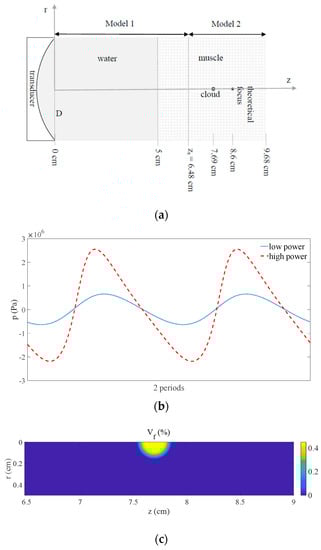
Figure 1.
(a) Schematic diagram of the problem. (b) Pressure waveform situated at on the symmetry axis in front of the cloud before transmitting into the bubble cloud at low () and high () powers. (c) Void fraction in the focal area showing the bubble cloud ().
During the propagation of ultrasound at high acoustic-pressure level through water and tissue, the wave is affected by nonlinear distortion and attenuation. When the sound wave interacts with the cloud located in the pre-focal zone, the bubbles exhibit nonlinear oscillations and the ultrasonic field undergoes changes due to bubble volume variations, since the bubbly medium is dispersive and nonlinear. The process can be described by coupling the pressure field and the oscillating bubble field. In addition, the bubble agglomerate provokes scattering and shielding of the acoustic field.
The ultrasonic field generated by the sonication at frequency is defined by the acoustic pressure and the bubble oscillations field is defined by the bubble-volume variation , both being functions of time . This three-dimensional problem is extremely complex to solve and would not be manageable for computations in practice. It is thus simplified by setting the variable as the angle of symmetry to reduce the mathematical problem to the plane. Acoustic pressure and bubble-volume variation are now functions of three variables: and .
The procedure developed for solving the problem is structured by splitting the simulation model into two coupled parts (Figure 1a): The acoustical problem is simplified by using the KZK approximation to compute the sound propagation between the transducer and a zone close to the bubble cloud (denoted by Model 1), whereas the bubble-sound interaction is simplified by using the RP approximation in the vicinity of the focus (denoted by Model 2). Model 1 simulates the nonlinear propagation of the focused ultrasound in the water and muscle tissue from the source at time up to the interface between both models at the distance at time [32], whereupon the simulated pressure field is used as an input for Model 2, which simulates the nonlinear interaction of the ultrasound wave and bubble oscillation field in the volume of soft tissue surrounding the bubble cloud [41].
Model 1 computes the propagation of nonlinear ultrasound in the domain , from to by simulating the propagation with the KZK equation:
where and are the equilibrium density and the small-amplitude sound speed of the homogeneous medium, respectively, is the retarded time, is the acoustic diffusivity related to the absorption, is the coefficient of nonlinearity of the medium, and denotes the Laplacian operator in the perpendicular plane to the propagation (index t refers to muscle tissue and index w refers to water). In both media, the attenuation follows the power-law , where and are specific parameters of the propagation medium. Details of the implementation of the model can be found in the previous work [32]. For parameter values used in Model 1, see Figure 1a and Section 3.
Model 2 assumes that the spherical gas bubbles are contained in a small volume of muscle next to the focus of the HIFU field. The void fraction in that volume is . The time-dependent acoustic-pressure output from Model 1 serves as input function for Model 2, which simulates the domain , from to the last instant of the study . The following coupled system of two differential equations, composed of the RP equation (written in variable ) and the wave equation [41,42,43], is solved after adding the adequate initial and boundary conditions (system at rest at time , imposition of the incident ultrasound field from Model 1 at , axial symmetry, and non-reflecting boundary conditions at and ) [41,45]:
In these Equations, is the resonance frequency of the bubbles (), is the viscous damping coefficient of the bubbly medium ( is the kinematic viscosity of the tissue), is the bubble density in the liquid, , the nonlinear coefficient associated to the adiabatic gas law is , the nonlinear coefficient associated to the dynamic response of bubbles is , and are the initial bubble radius and volume, respectively, and is the specific heat ratio of the gas. The difference between the current total volume and is . Details of the implementation of the model can be found in the previous works [41,46]. For parameter values used in Model 2, see Figure 1a and Section 3.
Model 1 takes the effects of diffraction, attenuation, and nonlinear propagation of ultrasound into account. The parabolic approximation for diffraction used to derive the model limits its validity to waves that mainly propagate in one preferred direction and sound beams with a moderate angular spectrum [32,47,48]. It is thus adapted to the focused propagation of ultrasound in the homogeneous media considered here (water and tissue without bubbles). Model 2 takes into account the nonlinear interaction of both the acoustic field and the bubble oscillations by considering and as unknown variables of the differential problem [41]. This matches the requirements to simulate the coupling of both fields in the pre-focal zone with bubbles. The model assumes restrictions that limit its validity to monodisperse spherical bubbles in populations with low void fraction and, since the nonlinear parameter of the bubbly medium is several orders of magnitude higher than that of the tissue [42,43], it does not take into account the nonlinear propagation effects in the medium where no bubbles are present [10,42,43,48,49]. We thus set close to the bubble cloud.
The coupling of both numerical models at requires the synchronization of the signal at the discretization points in the radial direction. This process does not add any numerical imprecisions. This task is made easier in Section 3 since the point number per wavelength in the radial direction is the same for both numerical models.
3. Results
The simulations were performed using a focused transducer with F-number of 2, diameter D of 5 cm, and radius of curvature of 10 cm, operating at that was positioned to deliver a focus at a depth of 3.6 cm in the muscle tissue (, , , , and ) through a water path (, , , , and ) [32]. The acoustic power was varied as . Following Section 1, an idealized air-bubble cloud of radius 0.15 cm was located at 0.91 cm in front of the focus, in which bubbles such that were considered with a void fraction in the range () [18,21]. The other parameter values of the cloud were: Sound speed in the air , air density , , , , , and [41]. The geometry of the simulation is shown in Figure 1a. Note that this configuration (geometry, ultrasound, cloud, and media) is set to define an idealized model simulation able to show the effects a bubbly cloud present in the pre-focal region induces on a HIFU field. However, other parameter values could be employed. For the simulations we used 64 points per wavelength radially for Model 1 and Model 2, 2 and 64 points per wavelength axially for Model 1 and Model 2, respectively, 100 and 99 points per cycle for Model 1 and Model 2, respectively, and 19 periods were computed with Model 2. The effect of nonlinear propagation in water and tissue on pressure is seen in Figure 1b by displaying the pressure waveform situated at on the symmetry axis in front of the cloud at low and high powers ( and ) before transmitting into the bubble cloud. The nonlinear distortion undergone by the signal due to the propagation through the water and muscle tissue at high power is clearly observed by comparing with the sine signal obtained at low power. The linear wave obtained at low power and the nonlinear wave obtained at high power will affect the bubble oscillations in the cloud in different ways. This cloud is seen in Figure 1c, which shows the void fraction distribution in the focal area of the axial plane. The MI defined as
in which is given in MHz and , the minimum amplitude of the negative pressure, is given in MPa [50], was studied under different values of and .
The impact of the bubble cloud with high void fraction on the pressure field at high power is presented in Figure 2b. The same case without cloud is shown in Figure 2a. We observe that harmonics are focused in different ways without bubbles, when the nonlinearity is due to the water and tissue only (Figure 2a), and with bubbles, when scattering due to the bubble cloud exists and the nonlinearity is due to the water, tissue, and bubbles (Figure 2b). The volumes of highest energy at each frequency strongly differ from one case to another. With bubbles, the distribution of energy mainly concentrates in front of the cloud and inside the cloud, whereas the harmonics produce an elongated volume of high energy around the axis without bubbles. Note that the depth of the pressure peak of each harmonic depends on all the parameters of the problem (ultrasonic field, cloud, nonlinear interaction of oscillating bubbles and ultrasound, scattering, and dispersion).
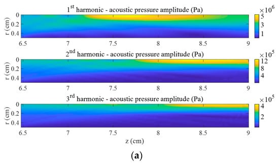
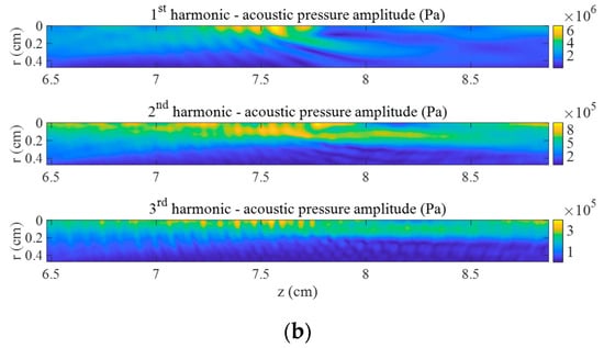
Figure 2.
First three harmonics of acoustic pressure in the focal area at . (a) Without bubbles and (b) with bubble cloud ().
The effects produced at high power by the bubble cloud with high void fraction on the MI are evidenced in Figure 3b by comparing to the same case without bubbles shown in Figure 3a. On one hand, we observe that the volume of tissue in which MI values are the highest is much smaller and is slightly shifted toward the front of the cloud. This change is provoked by the scattering due to the bubble cloud, as shown by the fringes seen in Figure 3b, and by the creation of highest pressure harmonics in this zone due to the nonlinearity of the oscillating bubbles (Figure 2). MI reaches higher values in the muscle with the cloud than without bubbles. On the other hand, a large volume of low MI values is observed beyond the cloud. The ultrasonic signal is drastically lowered there because of the shielding effect of the cloud on the incident focused ultrasound. The peak-to-peak pressure value at exhibits a loss of 69%.
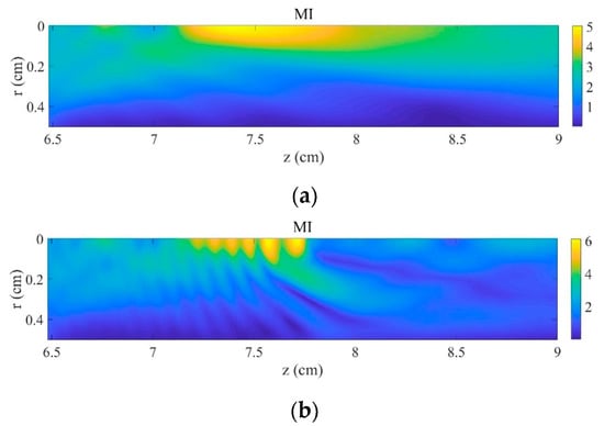
Figure 3.
Mechanical index in the focal area at . (a) Without bubbles and (b) with bubble cloud ().
The influence of acoustic power on MI values without bubbles and when the bubble cloud is set at high void fraction is displayed in Figure 4a. The difference of maximum MI values obtained with and without the bubble cloud increases as the sonication power is raised. MI reaches 6.04 at 300 W with bubbles, 20% above the value obtained without cloud at the same power. The position at which MI reaches its highest value at 300 W with bubbles is located at . It is shifted 1.82 mm toward the front of the cloud from its position obtained without bubbles. The effect of void fraction on the MI at high acoustic power is represented in Figure 4b by modifying the bubble density in the cloud. The MI values remain almost unperturbed at small and they increase rapidly as rises above this threshold.
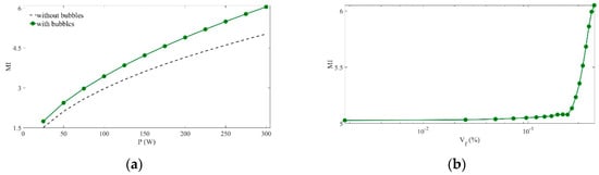
Figure 4.
Maximum mechanical index values. (a) versus acoustical power (), with () and without bubble cloud. (b) versus bubble density in the cloud (), with .
4. Discussion
Although some hypothesis and parameters used in the simulations do not fit exactly the ones in real HIFU situations, the results presented in this paper suggest that a bubble cloud located in the pre-focal area of a HIFU field can have a considerable effect on the ultrasound field. The interface between the soft tissue and the bubble cloud can generate scattering of the ultrasonic field, which can also be affected by nonlinear distortion. These phenomena can increase the MI values, modify the shape, change the location, and reduce the size of the volume of tissue of high MI values. Ultrasonic pressure is lowered beyond the bubble cloud. These conclusions are in concordance with experimental and numerical results available in the literature [15,18,21]. The increase in the MI value by 20% due to the bubble cloud observed here could have strong bioeffects, since the risk of damage in cell tissue from ultrasound (higher thermal and mechanical effects) would rise. Despite the restrictions of the theoretical models and their differences with experimental studies, the main results obtained here concerning the phenomenon of shielding and shifting of the intense volume of treatment agree with experimental data. Bubbles at a pre-focal position close to the theoretical focus induce intense rarefaction pressure in front of the bubbles and act as a barrier for ultrasound propagation. These results are important for HIFU treatments and suggest that bubble generation by cavitation should be monitored since the modification of the location, size, and shape of the highest MI volume observed in simulations suggest possible issues for safety purpose due to unintended damage of surrounding pre-focal tissue.
It must be noted that we chose to illustrate the use of the model with muscle tissue [32] in this idealized configuration, but the model can be applied to other tissues (liver tissue, other soft tissues, etc.) in which malignancies are treated by HIFU [50]. Also, other configurations different from the idealized case presented here need to be studied. It must be noted that the complexity of the problem, due in particular to the dispersion and nonlinearity of bubbly media, makes it possible to consider an infinity of different situations by using other bubble sizes, densities, geometries, source frequency to bubble resonance ratios, etc. Here we wanted to show the effects of a bubbly cloud on a HIFU field and to stress the necessity of taking these phenomena into account, but many parameters can be modified and many other varieties of situations can be studied. This specific model simulation is only the first step to understand the effect of the presence of a bubble cloud on the HIFU field. Other transducers with lower and higher F-numbers and other clouds with different geometries and bubble size distributions should be analyzed. The current simulation model includes restrictions (such as diffraction approximation of the KZK equation, monodisperse bubble requirement of the RP equation, no shear waves in tissues, etc.) that limit the validity of the simulations compared with real HIFU situations. It could be improved by considering, e.g., other nonlinear models for the propagation of ultrasound and bubble oscillations that would allow us to simulate the high-amplitude fields in more realistic bubbly media, with, in particular, lower bubble sizes. Further experimental research is required in real treatment cases. The effects caused by bubbles located in the water between the transducer and the skin should also be studied.
5. Conclusions
Numerical simulations have been performed to provide information on pre-focal effects due to a bubble cloud on a HIFU field. The numerical tool used here combines two existing numerical models and considers a nonlinear ultrasonic signal interacting with a population of nonlinearly oscillating bubbles confined in a cloud. The acoustic power of the focused transducer and the void fraction of the bubble cloud have been increased in the analysis. The numerical results suggest that a bubble cloud located in the pre-focal area can induce scattering and nonlinear distortion of the ultrasonic field that have important effects: The MI values are increased; the shape and location of the volume of tissue of high MI values are modified and its size is reduced; the pressure at the intended focus is lowered considerably. Although some hypothesis and parameters of the model and simulations do not fit exactly the real HIFU situations, this information is potentially of interest for HIFU treatments since the presence of a bubble cloud may have implications for the tissue in the pre-focal zone.
Author Contributions
Conceptualization, C.V. and K.H.; methodology, C.V. and K.H.; software, C.V. and K.H.; validation, C.V. and K.H..; formal analysis, C.V. and K.H.; investigation, C.V. and K.H.; resources, C.V. and K.H.; data curation, C.V.; writing—original draft preparation, C.V. and K.H.; writing—review and editing, C.V. and K.H.; visualization, C.V. and K.H.; supervision, C.V. and K.H.; project administration, C.V. and K.H.; funding acquisition, C.V.
Funding
This research was funded by the National Agency for Research of Spain and the European Regional Development Fund, grant number DPI2017-84758-P.
Acknowledgments
The authors acknowledge Aki Pulkkinen for fruitful discussions. C.V. dedicates this work to Cleofé Campos-Pozuelo.
Conflicts of Interest
The authors declare no conflict of interest. The funders had no role in the design of the study; in the collection, analyses, or interpretation of data; in the writing of the manuscript, or in the decision to publish the results.
References
- Tempany, C.M.C.; Stewart, E.A.; McDannold, N.; Quade, B.J.; Jolesz, F.A.; Hynynen, K. MR imaging-guided focused ultrasound surgery of uterine leiomyomas: A feasibility study. Radiology 2003, 226, 897–905. [Google Scholar] [CrossRef] [PubMed]
- Chapman, A.; ter Haar, G. Thermal ablation of uterine fibroids using MR-guided focused ultrasound: A truly non-invasive treatment modality. Eur. Radiol. 2007, 17, 2505–2511. [Google Scholar] [CrossRef] [PubMed]
- Gianfelice, D.G.; Gupta, C.; Kucharczyk, W.; Bret, P.; Havill, D.; Clemons, M. Palliative treatment of painful bone metastases with MR imaging-guided focused ultrasound. Radiology 2008, 249, 355–363. [Google Scholar] [CrossRef] [PubMed]
- Maestroni, U.; Ziveri, M.; Azzolini, N.; Dinale, F.; Ziglioli, F.; Campaniello, G.; Frattini, A.; Ferretti, S. High intensity focused ultrasound (HIFU): A useful alternative choice in prostate cancer treatment. Preliminary results. Acta Biomed. 2008, 79, 211–216. [Google Scholar]
- Furusawa, H.; Namba, K.; Nakahara, H.; Tanaka, C.; Yasuda, Y.; Hirabara, E.; Imahariyama, M.; Komaki, K. The evolving non-surgical ablation of breast cancer: MR guided focused ultrasound (MRgFUS). Breast Cancer 2007, 14, 55–58. [Google Scholar] [CrossRef]
- Jeanmonod, D.; Werner, B.; Morel, A.; Michels, L.; Zadicario, E.; Schiff, G.; Martin, E. Transcranial magnetic resonance imaging-guided focused ultrasound: noninvasive central lateral thalamotomy for chronic neuropathic pain. Neurosurg. Focus 2012, 32, E1. [Google Scholar] [CrossRef]
- Elias, W.J.; Huss, D.; Voss, T.; Loomba, J.; Khaled, M.; Zadicario, E.; Frysinger, R.C.; Sperling, S.A.; Wylie, S.; Monteith, S.J.; et al. A pilot study of focused ultrasound thalamotomy for essential tremor. N. Engl. J. Med. 2013, 369, 640–648. [Google Scholar] [CrossRef]
- Lipsman, N.; Schwartz, M.L.; Huang, Y.; Lee, L.; Sankar, T.; Chapman, M.; Hynynen, K.; Lozano, A.M. MR-guided focused ultrasound thalamotomy for essential tremor: A proof-of-concept study. Lancet Neurol. 2013, 12, 462–468. [Google Scholar] [CrossRef]
- Chung, A.H.; Hynynen, K.; Colucci, V.; Oshio, K.; Cline, H.E.; Jolesz, F.A. Optimization of spoiled gradient-echo phase imaging for in vivo localization of a focused ultrasound beam. Magn. Reson. Med. 1996, 36, 745–752. [Google Scholar] [CrossRef]
- Young, F.R. Cavitation; McGraw-Hill: London, UK, 1989; Available online: https://www.worldcat.org/title/cavitation/oclc/19521628 (accessed on 20 September 2019).
- Bai, L.; Xu, W.; Deng, J.; Li, C.; Xu, D.; Gao, Y. Generation and control of acoustic cavitation structure. Ultrason. Sonochem. 2014, 21, 1696–1706. [Google Scholar] [CrossRef]
- Zhao, L.-Y.; Zou, J.Z.; Chen, Z.-G.; Liu, S.; Jiao, J.; Wu, F. Acoustic cavitation enhances focused ultrasound ablation with phase-shift inorganic perfluorohexane nanoemulsions: An in vitro study using a clinical device. Biomed. Research Int. 2016, 2016, 7936902. [Google Scholar] [CrossRef]
- Hi, M.; Zhong, Z.; Li, X.; Gong, X.; Wang, Z.; Li, F. Effects of different hydrostatic pressure on lesions in ex vivo bovine livers induced by high intensity focused ultrasound. Ultrason. Sonochem. 2017, 36, 36–41. [Google Scholar]
- Wang, M.; Lei, Y.; Zhou, Y. High-intensity focused ultrasound (HIFU) ablation by the frequency chirps: Enhanced thermal field and cavitation at the focus. Ultrasonics 2019, 91, 134–149. [Google Scholar] [CrossRef]
- Qiao, Y.; Yin, H.; Chang, N.; Wan, M. Phase-shift nano-emulsions induced cavitation and ablation during high intensity focused ultrasound exposure, Proceeding from the 41th International Symposium on Therapeutic Ultrasound. AIP Conf. Proc. 2017, 1821, 040001. [Google Scholar]
- Pishchalnikov, Y.A.; Williams, J.C., Jr.; McAteer, J.A. Bubble proliferation in the cavitation field of a shock wave lithotripter. J. Acoust. Soc. Am. 2011, 130, EL87–EL93. [Google Scholar] [CrossRef]
- Gyöngy, M.; Coussios, C.C. Passive cavitation mapping for localization and tracking of bubble dynamics. J. Acoust. Soc. Am. 2010, 128, EL175–EL180. [Google Scholar] [CrossRef]
- Lo, A.H.; Kripfgans, O.D.; Carson, P.L.; Fowlkes, J.B. Spatial control of gas bubbles and their effects on acoustic fields. Ultrasound Med. Biol. 2006, 32, 95–106. [Google Scholar] [CrossRef]
- Zhang, S.; Li, C.; Zhou, F.; Wan, M.; Wang, S. Enhanced lesion-to-bubble ratio on ultrasonic Nakagami imaging for monitoring of high-intensity focused ultrasound. J. Ultrasound Med. 2014, 33, 959–970. [Google Scholar] [CrossRef]
- Elbes, D.; Denost, Q.; Robert, B.; Köhler, M.O.; Tanter, M.; Bruno, Q. Magnetic resonance imaging for the exploitation of bubble-enhanced heating by high-intensity focused ultrasound: a feasibility study. Ultrasound Med. Biol. 2014, 40, 956–964. [Google Scholar] [CrossRef]
- Hosseini, S.H.R.; Zheng, X.; Vaezy, S. Effects of gas pockets on high-intensity focused ultrasound field. IEEE Trans. Ultrason. Ferroelectr. Freq. Control 2011, 58, 1203–1210. [Google Scholar] [CrossRef]
- Sapareto, S.; Dewey, W. Thermal dose determination in cancer therapy. Int. J. Radiat. Oncol. Biol. Phys. 1984, 10, 787–800. [Google Scholar] [CrossRef]
- Williams, R.; Cherin, E.; Lam, T.Y.J.; Tavakkoli, J.; Zemp, R.J.; Foster, F.S. Nonlinear ultrasound propagation through layered liquid and tissue-equivalent media: computational and experimental results at high frequency. Phys. Med. Biol. 2006, 51, 5809–5824. [Google Scholar] [CrossRef]
- Canney, M.S.; Bailey, M.R.; Crum, L.A.; Khokhlova, V.A.; Sapozhnikov, O.A. Acoustic characterization of high intensity focused ultrasound fields: a combined measurement and modeling approach. J. Acoust. Soc. Am. 2008, 124, 2406–2420. [Google Scholar] [CrossRef]
- Khokhlova, T.D.; Canney, M.S.; Lee, D.; Marro, K.I.; Crum, L.A.; Khokhlova, V.A.; Bailey, M.R. Magnetic resonance imaging of boiling induced by high intensity focused ultrasound. J. Acoust. Soc. Am. 2009, 125, 2420–2431. [Google Scholar] [CrossRef]
- Tavakkoli, J.; Cathignol, D.; Souchon, R.; Sapozhnikov, O.A. Modeling of pulsed finite-amplitude focused sound beams in time domain. J. Acoust. Soc. Am. 1998, 104, 2061–2072. [Google Scholar] [CrossRef]
- Liu, X.; Li, J.; Gong, X.; Zhang, D. Nonlinear absorption in biological tissue for high intensity focused ultrasound. Ultrasonics 2006, 44, e27–e30. [Google Scholar] [CrossRef]
- Zemp, R.J.; Tavakkoli, J.; Cobbold, R.S.C. Modeling of nonlinear ultrasound propagation in tissue from array transducers. J. Acoust. Soc. Am. 2003, 113, 139–152. [Google Scholar] [CrossRef]
- Zeng, X.; McGough, R.J. Evaluation of the angular spectrum approach for simulations of near-field pressures. J. Acoust. Soc. Am. 2008, 123, 68–76. [Google Scholar] [CrossRef]
- Jing, Y.; Cleveland, R.O. Modeling the propagation of nonlinear three dimensional acoustic beams in inhomogeneous media. J. Acoust. Soc. Am. 2007, 122, 1352–1364. [Google Scholar] [CrossRef]
- Yang, X.; Cleveland, R.O. Time domain simulation of nonlinear acoustic beams generated by rectangular pistons with application to harmonic imaging. J. Acoust. Soc. Am. 2005, 117, 113–123. [Google Scholar] [CrossRef]
- Pulkkinen, A.; Hynynen, K. Computational aspects in high intensity ultrasonic surgery planning. Computerized Med. Imaging Graphics 2010, 34, 69–78. [Google Scholar] [CrossRef]
- Filnonenko, E.A.; Khokhlova, V.A. Effect of acoustic nonlinearity on heating of biological tissue by high-intensity focused ultrasound. Acoust. Phys. 2001, 47, 468–475. [Google Scholar] [CrossRef]
- Khokhlova, V.A.; Bailey, M.R.; Reed, J.A.; Cunitz, B.W.; Kaczkowski, P.J.; Crum, L.A. Effects of nonlinear propagation, cavitation, and boiling in lesion formation by high intensity focused ultrasound in a gel phantom. J. Acoust. Soc. Am. 2006, 119, 1834–1848. [Google Scholar] [CrossRef]
- Matula, T.J.; Cordry, S.M.; Roy, R.A.; Crum, L.A. Bjerknes force and bubble levitation under single-bubble sonoluminescence conditions. J. Acoust. Soc. Am. 1997, 102, 1522–1527. [Google Scholar] [CrossRef]
- Bakhtiari-Nejad, M.; Shahab, S. Effects of nonlinear propagation of focused ultrasound on the stable cavitation of a single bubble. Acoustics 2019, 1, 14–34. [Google Scholar] [CrossRef]
- Karpov, S.; Prosperetti, A.; Ostrovsky, L. Nonlinear oscillations of bubble layers. J. Acoust. Soc. Am. 2003, 113, 1304–1316. [Google Scholar] [CrossRef]
- Servant, G.; Laborde, J.L.; Hita, A.; Caltagirone, J.P.; Gérard, A. On the interaction between ultrasound waves and bubble clouds in mono- and dual-frequency sonoreactors. Ultrason. Sonochem. 2003, 10, 347–355. [Google Scholar] [CrossRef]
- Vanhille, C.; Campos-Pozuelo, C. Nonlinear ultrasonic propagation in bubbly liquids: a numerical model. Ultrasound Med. Biol. 2008, 34, 792–808. [Google Scholar] [CrossRef]
- Vanhille, C.; Campos-Pozuelo, C. Nonlinear ultrasonic waves in bubbly liquids with nonhomogeneous bubble distribution: numerical experiments. Ultrason. Sonochem. 2009, 16, 669–685. [Google Scholar] [CrossRef]
- Vanhille, C.; Campos-Pozuelo, C. Numerical simulations of three-dimensional nonlinear acoustic waves in bubbly liquids. Ultrason. Sonochem. 2013, 20, 963–969. [Google Scholar] [CrossRef]
- Hamilton, M.F.; Il’Inskii, Y.A.; Zabolotskaya, E.A. Dispersion. In Nonlinear Acoustics; Hamilton, M.F., Blackstock, D.T., Eds.; Academic Press: San Diego, CA, USA, 1998; pp. 151–175. [Google Scholar]
- Saito, S. Ultrasound field and bubbles. In Sonochemistry and the Acoustic Bubble; Grieser, F., Choi, P.K., Enomoto, N., Harada, H., Okitsu, K., Yasui, K., Eds.; Elsevier: Amsterdam, The Netherlands, 2015; pp. 11–39. [Google Scholar]
- Vanhille, C.; Pulkkinen, A.; Hynynen, K.; Campos-Pozuelo, C. Efectos de una nube de burbujas en un campo HIFU. In Proceedings of the Congress on Numerical Methods in Engineering, Bilbao, Spain, 25–28 June 2013; Universidad del País Vasco: Bilbao, Spain. [Google Scholar]
- Blackstock, D.T. Fundamentals of Physical Acoustics; John Wiley and Sons: New York, NY, USA, 2000. [Google Scholar]
- Vanhille, C.; Campos-Pozuelo, C. Nonlinear interaction of air bubbles and ultrasonic field: an analysis of some physical aspects. In Recent Development in Nonlinear Acoustics, AIP Conference Proceedings 1685; Blanc-Benon, P., Sparrow, V.W., Dragna, D., Eds.; American Institute of Physics Publishing: Melville, NY, USA, 2015; p. 050008. [Google Scholar]
- Verweij, M.D.; Huijssen, J. Computational methods for nonlinear acoustic wavefields in homogeneous media. In Computational Methods in Nonlinear Acoustics: Current Trends; Vanhille, C., Campos-Pozuelo, C., Eds.; Research Signpost: Kerala, India, 2011; pp. 1–19. [Google Scholar]
- Naugolnykh, K.; Ostrovsky, L. Nonlinear Wave Processes in Acoustics; Cambridge University Press: New York, NY, USA, 1998. [Google Scholar]
- Zabolotskaya, E.A.; Soluyan, S.I. Emission of harmonic and combination-frequency waves by air bubbles. Sov. Phys. Acoust. 1973, 18, 396–398. [Google Scholar]
- Wu, J.; Nyborg, W.L. Emerging Therapeutic Ultrasound; World Scientific: Hackensack, NJ, USA, 2006. [Google Scholar]


© 2019 by the authors. Licensee MDPI, Basel, Switzerland. This article is an open access article distributed under the terms and conditions of the Creative Commons Attribution (CC BY) license (http://creativecommons.org/licenses/by/4.0/).