Article

On the Incipient Indicial Lift of Thin Wings in Subsonic Flow: Acoustic Wave Theory with Unsteady Three-Dimensional Effects

Pilatus Aircraft Ltd., 6371 Stans, Switzerland
Acoustics 2022, 4(1), 26-52; https://doi.org/10.3390/acoustics4010003
Submission received: 25 November 2021 / Revised: 11 January 2022 / Accepted: 12 January 2022 / Published: 18 January 2022

Abstract

:
Enhanced approximate expressions for the incipient indicial lift of thin wings in subsonic potential flow are presented in this study, featuring explicit analytical corrections for the unsteady downwash. Lifting-line and acoustic-wave theories form the basis of the method, within an effective synthesis of the governing physics, which grants a consistent generalised framework and unifies previous works. The unsteady flow perturbation consists of a step-change in angle of attack or a vertical sharp-edged gust. The proposed model is successfully evaluated against numerical results in the literature for the initial airload development of elliptical and rectangular wings with a symmetric aerofoil, considering several aspect ratios and Mach numbers. While nonlinear downwash and compressibility terms demonstrate marginal (especially for the case of a travelling gust), both linear and nonlinear geometrical effects from a significant taper ratio, sweep angle or curved leading-edge are found to be more important than linear downwash corrections (which are crucial for the circulation growth at later times instead, along with linear compressibility corrections). The present formulae may then be used as a rigorous reduced-order model for validating higher-fidelity tools and complex simulations in industrial practice, as well as for estimating parametric sensitivities of unsteady aerodynamic loads within the preliminary design of aircraft wings in the subsonic regime.

1. Introduction

Especially within aeroplane multidisciplinary design and optimisation (MDO) [1,2], unsteady airloads from pilot manoeuvres or atmospheric turbulence may effectively be calculated by adopting aerodynamic indicial-admittance functions [3,4] as reduced-order models (ROMs) [5,6], particularly for sensitivity and uncertainty evaluation purposes [7,8,9]. For thin aircraft wings at moderate angles of attack, the viscous effects are confined in a thin boundary layer and wake [10]; Euler’s nonlinear model [11] can then numerically be employed for calculating the unsteady aerodynamic loads due to compressible inviscid air (considered as an ideal polytrophic gas at a given flight altitude [12]) from the subsonic to the supersonic regime, with or without shock waves [13]. By further assuming isentropic potential flow as practical [14], theoretical solutions for the propagation of small disturbances are available from acoustic wave theory and method of characteristics [15] in both subsonic and supersonic regimes without transonic bubbles [16,17]. Exploiting Prandtl–Glauert’s transformation [18,19], exact results for incompressible potential flow can also be generalised for low-speed compressible flow in the subsonic regime [20]; of course, the accuracy of such an approximation depends on the rigorous applicability of the underlying fluid mechanics similitude and deteriorates with increasing Mach number towards the transonic regime [21,22].
Based on these premises [23,24], a few analytical formulations have been published for the lift development of thin aerofoils C l ( τ ) [25,26,27,28,29,30,31,32] and finite wings C L ( τ ) [33,34,35,36] in subsonic potential flow [37,38,39,40,41], linearly superposing circulatory C ˇ l ( τ ) , C ˇ L ( τ ) and non-circulatory C ^ l ( τ ) , C ^ L ( τ ) contributions from a step in the angle of attack (AOA) or a vertical sharp-edged gust (SEG) in reduced time τ [42]. Computational fluid dynamics (CFD) [43] has also increasingly been used to improve accuracy and generality [44,45,46,47,48], but it remains computationally expensive and requires special care [49], with significant efforts to pre-process the simulations and post-process the results on the numerical grid [50]. Hybrid approaches [51,52] and multifidelity tuning strategies [53,54] have then been proposed that still rely on robust lower-fidelity models at their core [55,56,57,58]. However, no parametric theoretical model is available that accounts for three-dimensional effects from flow unsteadiness and gust penetration in compressible air without shock waves, especially when the perturbation front is normal to the reference stream.
This study introduces explicit analytical corrections for the unsteady downwash and enhances approximate expressions for the indicial lift of thin aircraft wings in the subsonic regime, within an effective synthesis of the governing physics, which grants a consistent generalised framework and unifies previous works. The non-circulatory airload development (rapidly decaying after the perturbation onset) is based on acoustic wave theory [59], whereas the circulatory counterpart (gradually reaching the asymptotic steady state) is based on lifting-line theory [60] with Prandtl–Glauert’s compressibility corrections [61]; the same aerofoil and reference angle of attack α are assumed for all wing sections. In the presence of a leading-edge curvature or a sweep angle Λ , the latter hit the atmospheric gust at a different time, while a progressive portion of wing span is impinged from root (with no delay) to tip (with full delay); both chordwise and spanwise penetration effects are then taken into account. The analytical approach provides sound physical insights for practical validation purposes [62] and may efficiently be used to assess the necessary trade-off between detailed complexity and computational costs of higher-fidelity tools in the aviation industry [63]. Considering AOA and SEG perturbations, theoretical results are obtained and critically compared with numerical ones in previous publications for thin airfoil at different Mach numbers [64], elliptical wings with different aspect ratio [65], and rectangular wings with different sweep angle [66]; all comparisons are explained and clarified in light of the proposed analytical derivation, within a comprehensive assessment.

2. Governing Physics: From Nonlinear Compressible to Linear Incompressible Flow

Starting from Euler’s nonlinear equations for compressible fluid and ending with Laplace’s linear equation for incompressible fluid [23,24], the different models that have been exploited to propagate acoustic disturbances in inviscid flow are hereafter systematically derived within a unified approach that explains the underlying physical assumptions and mathematical approximations. In all cases, atmospheric air at a given flight altitude is suitably considered as an ideal polytrophic gas with thermodynamic state given by [13]:
p   =   ρ R T , a   =   γ R T , E   =   c v T , H   =   c p T , R   =   c p c v ,
where ρ ( s , t ) is the density, T ( s , t ) the temperature, p ( s , t ) the pressure, a ( s , t ) the sound speed, E ( s , t ) the internal energy, and H ( s , t ) the enthalpy of the gas as functions of both physical space s = ( x , y , z ) and time t; R is the gas constant, with c p the isobaric and c v the isochoric heat capacities.
In the absence of body forces and heat transfer, Euler’s system of coupled nonlinear partial differential equations (PDEs) for the conservation of mass, momentum, and total energy reads [13]:
ρ t   +   · ρ ν   =   0 , t ρ ν   +   · p I   +   ρ ν ν   =   0 ,
t ρ E   +   ν 2 2   +   · ν p   +   ρ E   +   ν 2 2   =   0 ,
E   =   p γ 1 ρ , H   =   γ p γ 1 ρ , M   =   ν a ,
where ν ( s , t ) and M ( s , t ) are the flow velocity and Mach number, respectively, whereas the conservation of total energy may be replaced by the conservation of entropy S ( s , t ) , namely [13]:
S t + ν · S   =   0 , Δ S   =   c v ln p ρ γ , γ   =   c p c v ,
with γ the heat capacity ratio and H   =   γ E ; Crocco’s theorem then gives pressure and entropy gradients as [11]:
p   =   ρ H T S , T S   =   H   +   ν 2 2   +   ν t ν × ω , ω   =   × ν ,
with ω ( s , t ) the vorticity vector. By writing Euler’s equations in advective form and calculating the eigenvalues of the flux matrix, it is found that disturbances are conveyed with speeds ν and a ± ν [13]; Rankine–Hugoniot’s conditions [67] must then also be enforced in order to ensure feasible shock waves in the transonic or supersonic flow regime (i.e., for M 1 or M > 1 , respectively). For the case of isentropic flow (i.e., for Δ S   =   0 ), the equations for the state of the ideal gas simplify as [13]:
p   =   ρ γ , T   =   ρ γ 1 R , a   =   γ ρ γ 1 , E   =   ρ γ 1 γ 1 , H   =   γ ρ γ 1 γ 1 ,
and the conservation of total energy becomes redundant; therefore, disturbances travel with speeds a ± ν only [68]. In any case, appropriate Neumann’s and Dirichlet’s boundary conditions complete the set of governing equations [43], as imposed on the impermeable wing surface s w and the unperturbed far field s , respectively:
ν ( s w , t ) · n ( s w , t )   =   0 , ν ( s , t )   =   ν , p ( s , t )   =   p , S ( s , t )   =   S ,
where n ( s w , t ) is the vector normal to the body surface (which may also move, in general, within the broader perspective of fluid–structure interactions [69]). The occurrence of a wind gust may then be simulated by prescribing a disturbance ν G ( s , t ) of the free-stream, and different methods can be adopted to this purpose, with or without mutual interaction with the wing [70] (e.g., thru a velocity field that either advances through the computational domain as part of the flow solution or is superposed to the unperturbed airstream with a transpiration-like technique according to the “frozen” approach [71], respectively). When the equations above for inviscid flow can be linearised in the presence of small disturbances, the latter travel with speeds a ± ν , and classical acoustic theory for sound propagation is obtained directly [13,59].
Assuming irrotational flow (i.e., for ω   =   0 ) as practical [14,62], the velocity potential φ ( s , t ) can be defined and is governed by a single nonlinear PDE complemented by the conservation of both entropy and enthalpy along streamlines, namely [23,24]:
2 φ   =   1 a 2 t φ t   +   ν 2   +   ν · ν 2 2 , ν   =   φ ,
a 2 γ 1   +   ν 2 2   +   φ t   =   a 2 γ 1   +   ν 2 2 , S   =   S ,
which can propagate weak shock waves of isentropic behaviour in the low-supersonic regime [72], since the related entropy variations are of higher order, and first-principle integral constraints such as the “equal area rule” grant a physically consistent solution by fitting the necessary flow discontinuities [13,59]. The pressure coefficient C p ( s w , t ) then reads [23,24]:
C p   =   2 γ M 2 p p 1 , p p   =   a a 2 γ γ 1 ,
and can be integrated over the wing surface in order to obtain the applied aerodynamic force and moment coefficients. Considering an horizontal free-stream ν   =   ( U , 0 , 0 ) and a disturbance potential ϕ ( x , t ) for small acoustic perturbations, the principle of superposition applies, and the equations for the velocity potential can be linearised as [23,24]:
φ   =   U x   +   ϕ , ν   =   ν   +   ϕ , 2 ϕ   =   1 a 2 t ϕ t   +   2 U ϕ x   +   U 2 2 ϕ x 2 ,
a 2 γ 1   +   ϕ t   +   U ϕ x   =   a 2 γ 1 , C p   =   2 U ϕ x   +   1 U ϕ t ,
which can propagate acoustic waves and be solved using the method of characteristics [13,15,59]; in particular, the PDE for the disturbance potential in the subsonic regime (i.e., for M < 1 ) reads [23,24]:
β 2 2 ϕ x 2   +   2 ϕ y 2   +   2 ϕ z 2   =   M 2 U 2 2 ϕ t 2   +   2 U 2 ϕ x t , β   =   1 M 2 ,
where Prandtl–Glauert’s compressibility factor β [18,19] appears explicitly and drives the slope of the characteristic lines [15].
For an incompressible fluid (i.e., for Δ ρ   =   0 ), thermodynamic laws do not apply as the density is constant and the sound speed is infinite (i.e., M   =   0 regardless the flow speed) [13]; therefore, Laplace’s equation governs the disturbance potential and Bernoulli’s linearised equation gives the pressure as [23,24]:
2 ϕ   =   0 , p   +   ρ ϕ t   +   U ϕ x   =   p , C p   =   2 p ρ U 2 p p 1 ,
where the resulting expression for the pressure coefficient consistently coincides with that already found for linearised subsonic flow, as indeed assumed for low-speed aerodynamics [10]. In fact, this fundamental analogy in the subsonic regime holds for the governing equation of the disturbance potential too, as the latter for compressible flow reduces to Laplace’s equation for incompressible flow when Prandtl–Glauert’s transformation is enforced at low Mach numbers [61]; in particular, taking advantage of the compressibility factor to scale the physical quantities conveniently and hence obtain theoretical results for compressible flow from those for incompressible flow [20,73,74,75], the longitudinal dimension is divided by β and so are the pressure coefficient and the resulting aerodynamic loads [18,19].

3. Incompressible Potential Flow: Lifting-Line Theory

A generic aircraft wing has a chord distribution c ( y ) along its semi-spans 0 y ± l from root to tips; thus, its planform area A, aspect ratio η and taper ratio λ can generally be written as:
A   =   2 l r c r , η   =   2 l r c r , r   =   c a c r , λ   =   c t c r ,
where c a , c r , and c t are the average, root and tip chords, respectively; the chord ratio r refers to the mean wing section. Due to the pressure difference between upper and lower wing surfaces, a vortex generates at each of the two tips that induces a downwash velocity along the wing span and thus reduces the effective angle of attack and related sectional airloads [76]. For subsonic potential flow, Kelvin and Stokes’ theorems impose the conservation of total null circulation on all streamlines of a simply connected region (e.g., along closed paths) [77]. Applying Biot–Savart’s law [10] to a sheet of infinite horseshoe vortices with bound circulation placed at the line of the aerodynamic centres (i.e., at the first-quarter chord of the wing sections [78]), unsteady lifting-line theory [79,80,81] accounts for the downwash induced by the wing’s tip vortices, while Kutta–Joukowski’s theorem [82,83] relates the wake’s inflow with the quasi-steady wing’s circulation and Neumann’s impermeability condition [84] (i.e., flow tangential to the wing’s mean line) is enforced at the line of the control points (i.e., at the third-quarter chord of the wing sections [78]).
For nearly elliptic loading of a slender wing, all sections along the span experience roughly the same instantaneous downwash angle α i ( τ ) and angle of attack α ( τ ) [85]; therefore, by taking advantage of the problem symmetry, the body impermeability condition is checked at the control point of the wing’s root section directly, and the evolution of the airload is sought in the reduced time τ , which represents the number of travelled root semi-chords [86]. Reconstructing such an ideal lift distribution with a series of adjacent horseshoe vortices [10], the lift-deficiency C ˇ L ( τ ) and circulation-deficiency C ˇ Γ ( τ ) coefficients for the wing are given by:
e C ˇ L   =   C ˇ l / α α α i 0 0 τ C ˇ l / α τ ξ d α i d ξ d ξ , α   =   α α i , τ   =   2 U t c r ,
e C ˇ Γ   =   C ˇ γ / α α α i 0 0 τ C ˇ γ / α τ ξ d α i d ξ d ξ , α i   =   α Γ C ˇ Γ 0   +   0 τ α Γ τ ξ d C ˇ Γ d ξ d ξ ,
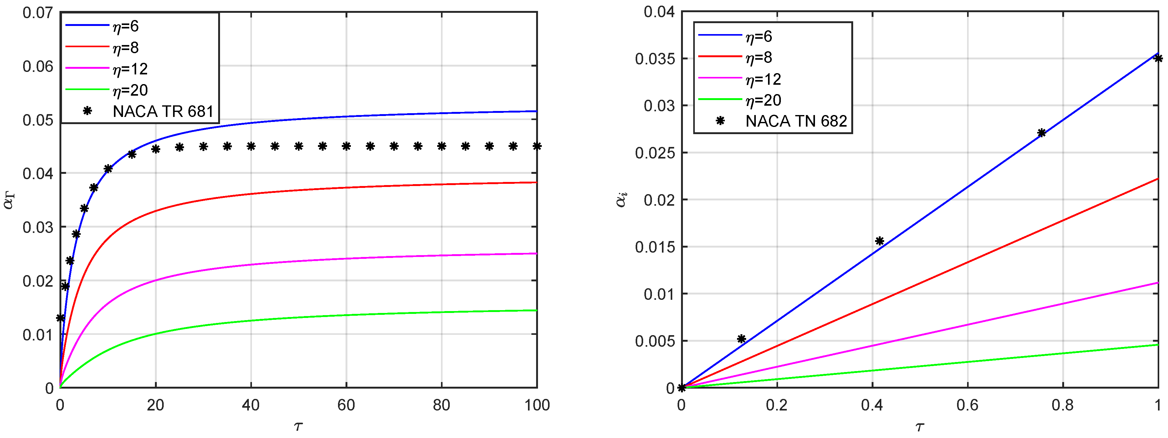
where e is the ratio of the semiperimeter to the span [87], whereas α Γ ( τ ) is the normalised gradient of the downwash angle with respect to the circulation Γ r ( τ ) at the wing root; C ˇ l / α ( τ ) and C ˇ γ / α ( τ ) are the derivatives of the indicial lift-deficiency and circulation-deficiency coefficients for the isolated aerofoil and account for the flat wake’s inflow as the vortex loops extend behind the wing [88,89]. Inherently improving previous formulations [90], note that the circulatory wing airload is consistently scaled by the edge-velocity factor [87] at all times; still, wing circulation and downwash angle are coupled, while the wing lift depends on the latter only. Especially at the asymptotic condition, the downwash angle makes the circulatory wing airload always lower than the aerofoil’s one [76,91], which is correctly resumed for infinitely slender wing (i.e., for e 1 and α i 0 ); thus, the steady condition is reached earlier than in the latter case despite the lower build-up rate. Imposing the initial rest conditions α i 0   =   0 , C Γ 0   =   0 , integrating by parts and substituting the two-dimensional indicial load derivatives for either a step in the angle of attack or a sharp-edged gust, the system of convolution equations can numerically be solved via the operational method [92,93] using the most appropriate integration scheme [94]. Disregarding spanwise penetration effects, Figure 1 shows the indicial circulatory lift from a step in the angle of attack and a vertical sharp-edged gust for elliptical thin wings with different aspect ratio in incompressible flow; literature results are also depicted for η   =   6 and well approximated with a single exponential term [86] (whereas additional ones are needed for higher aspect ratio, due to longer transition to the steady state [90]): while the initial lift coincides and the subsequent transition to the steady state has similar duration, the present enhanced model gives a slightly lower asymptotic lift because of the edge-velocity factor [87] (see Appendix A).
In fact, the convolution-based expressions become even more useful for finding the initial behaviour of the indicial lift and circulation functions [95]; in particular, taking advantage of Taylor’s expansion [94], at small or large times the lifting-line equations reduce to a linear algebraic system:
lim ξ 0 e C ˇ L C ˇ l / α α α i , lim ξ 0 e C ˇ Γ C ˇ γ / α α α i , lim ξ 0 α i α Γ C ˇ Γ ,
where the ratio between lift and circulation coefficients is confirmed to be approximately the same for both three-dimensional and two-dimensional flows [66]. It is worth stressing that a non-circulatory contribution C ^ L ( τ ) exists from a step-change in the angle of attack of an incompressible flow [96], in the form of a Dirac-delta singularity [94] that generates apparent inertia at the start of the airload development [4]; however, this well-known effect is irrelevant for the scope of the present work on compressible flow.
Alongside other formulations in the time domain [97,98,99,100,101,102,103,104,105,106], note that alternative approaches [107,108,109,110,111,112,113,114,115,116,117,118,119,120,121,122,123,124,125,126,127] have been proposed that lead to a frequency-dependent generalisation of lifting line theory, but their formulation is less convenient for deriving explicit expressions of the incipient indicial airload, as they specialise in harmonic motion and their inherent complexity is often not practical [128]. Nevertheless, they assess when two- and three-dimensional effects may actually be decoupled as well as show that for slender wings the downwash from the tip vortices can roughly be assumed as constant along the chord of each section (unlike the wake’s inflow) and affects the circulatory airload only [129,130].

3.1. Thin Aerofoils: Two-Dimensional Wake Inflow and Chordwise Gust Penetration

For small perturbations of the potential flow, a thin wake departs from the wing’s trailing edge (which represents a stagnation point [88,89]) to convey equal and opposite variations of the sectional bound circulation and hence satisfy Kelvin and Stokes’ theorems at all times [10,23]; the counteracting shed vorticity generates an inflow over the aerofoil in turn, while the unloaded wake travels with the free-stream towards the far field along a flat trajectory (as roll-up phenomena are suitably ignored, preserving the linearity of the unsteady aerodynamic model [52]). In the case of a step in angle of attack, the derivatives of the indicial lift-deficiency C ˇ l / α ( τ ) and circulation-deficiency C ˇ γ / α ( τ ) coefficients for the isolated two-dimensional sections of the thin wing in incompressible flow are given by Wagner [131] and Kussner [132] and exploit Theodorsen’s [133] and Sears’ [134] impulsive transfer functions in the reduced frequency domain, respectively. The circulation growth being asymptotically delayed by a travelled semichord [93], the derivative of Wagner’s indicial circulation-deficiency coefficient for a step in angle of attack incidentally coincides with that of Kussner’s indicial lift-deficiency coefficient C ˇ l / α ( τ ) from a sharp-edged gust (i.e., C ˇ l / α C ˇ γ / α directly) and includes chordwise penetration effects on the sectional airload build-up, while the derivative of the indicial circulation-deficiency coefficient C ˇ γ / α ( τ ) is asymptotically delayed by a further travelled semichord [135] (see Appendix A).
In particular, building on reciprocal relations [136,137] within the standard “frozen” approach [71], the derivative of the indicial circulation-deficiency coefficients can be written as:
C ˇ γ / α 0 τ C ˇ l / α τ ξ ξ 2 ξ d ξ π + 2 τ 2 τ 0 2 C ˇ l / α τ ξ ξ 2 ξ d ξ π C ˇ γ / α 0 τ C ˇ l / α τ ξ ξ 2 ξ d ξ π τ 2 , 0 2 C ˇ l / α τ ξ ξ 2 ξ d ξ π τ 2 ,
where τ = 2 is the reduced time taken by the gust to impinge the entire chord at the wing root, whereas the radical term outside the integral expresses the quasi-steady progressive increment of the effective angle of attack; of course, spanwise penetration effects are not included but the last two formulae hold for finite wing as well if C ˇ l / α and C ˇ γ / α are, respectively, replaced with e C ˇ L / α and e C ˇ Γ / α . According to Kutta–Joukowski’s theorem [82,83], the lift development always acts at the aerofoil’s first-quarter chord, while the impermeability boundary condition is consistently satisfied at the third-quarter chord [128]. Taking advantage of Taylor’s expansion, the limit behaviours of these fundamental indicial-admittance functions for a step in the angle of attack and a vertical sharp-edged gust are given by:
lim τ 0 C ˇ l / α π 1   +   τ 4 , lim τ 0 C ˇ γ / α 2 2 τ 1 τ 12 , lim τ 0 C ˇ γ / α 4 τ 2 3 π ,
lim τ C ˇ l / α 2 π 1 1 τ , lim τ C ˇ γ / α 2 π 1 1 τ 1 , lim τ C ˇ γ / α 2 π 1 1 τ 2 ,
where the incipient indicial circulation is seen to introduce second-order effects in the latter case. Figure 2 shows the exact indicial-admittance functions along with their incipient approximations; note that higher-order terms are indeed marginal during the chordwise penetration of the gust (i.e., for the incipient indicial circulation from a step in the angle of attack).

3.2. Thin Wings: Three-Dimensional Downwash Angle and Spanwise Gust Penetration

For a marginal sweep angle (i.e., with Λ < 15 [23,138]), the downwash angle and its gradient introduce most of the three-dimensional effects on the unsteady circulation Γ y , τ of slender wings in subsonic flow, with the non-dimensional wake development υ ( τ ) being given by Joukowski’s transform for the mean geometric section [85]. Biot-Savart’s law [10,14] gives an approximate expression of the normalised downwash gradient for nearly elliptic loading as [86]:
α Γ = 2 κ π 2 υ I s 1 , s = η η 2 + υ 2 , υ = τ 2 + τ , Γ Γ r 1 + y 2 l 2 ,
where I ( s ) is the complete elliptic integral of the second kind [139] and s ( υ ) is its non-dimensional argument. These expressions can then be used to solve the unsteady lifting-line problem numerically, where the shape factor κ ( η , e ) may be interpreted as the inverse of Oswald’s efficiency factor [140,141] and account for higher-order deviations from ideal elliptic loading [142,143] (with κ 1 ); it may also be exploited to introduce higher-order corrections or fine-tuning [53,54]. At small time values, the initial behaviours and incipient solution read:
lim τ 0 υ 2 τ , lim τ 0 α Γ g τ 2 , lim τ 0 α i 2 e g τ α , g = κ 1 + ln 8 η 2 π 2 η 2 ,
where higher-order terms are consistently neglected and so is the incipient downwash during the chordwise penetration of a vertical sharp-edged gust (especially with normal front, due to a further mitigation from the spanwise penetration); g is the downwash gradient factor. Figure 3 shows the approximate downwash gradient and incipient angle from a step in the angle of attack for thin elliptical wings in incompressible flow; literature results are also depicted for η = 6 and initially well-approximated with a single exponential term [86], although being shifted by a mean geometric chord and eventually converging to an incorrect asymptotic value [90] (regardless of the actual absence of the edge-velocity factor, as far as the downwash gradient is concerned). At large time values, instead, the asymptotic behaviours and steady-state solution read:
lim τ υ τ + 1 , lim τ α Γ κ π η , lim τ α i 2 κ α e η + 2 κ ,
where Jones’ correction [87] is directly embedded and a consistent improvement of Prandtl’s results [76] is hence obtained (see Appendix A).
For a significant sweep angle (i.e., with Λ > 15 [23,138]), the effective free-stream relative to the isolated two-dimensional sections acts normal to the quarter-chord line along the wing span (i.e., the aerodynamic axis the sweep angle refers to [24]); therefore, horizontal velocity as well as lift and circulation coefficients are thereby projected and coherently scaled by cos Λ [144]. The circulatory responses from a step in the angle of attack and a vertical sharp-edged gust then start off as:
lim τ 0 C ˇ L π e 1   +   1 4 2 e g cos Λ τ α cos Λ , lim τ 0 C ˇ L 2 e 2 τ 1 τ 12 α cos Λ ,
respectively, where higher-order terms have been discarded and e pertains to the straight wing; note that these very practical expressions account for the effects of wing slenderness, chord tapering, and small deviations (including possible nonlinear ones) from ideal elliptic loading. Figure 4 shows the incipient lift of elliptical thin wings in incompressible flow from a step in the angle of attack and a vertical sharp-edged gust; still, note that higher-order terms remain marginal during the chordwise penetration of the gust.
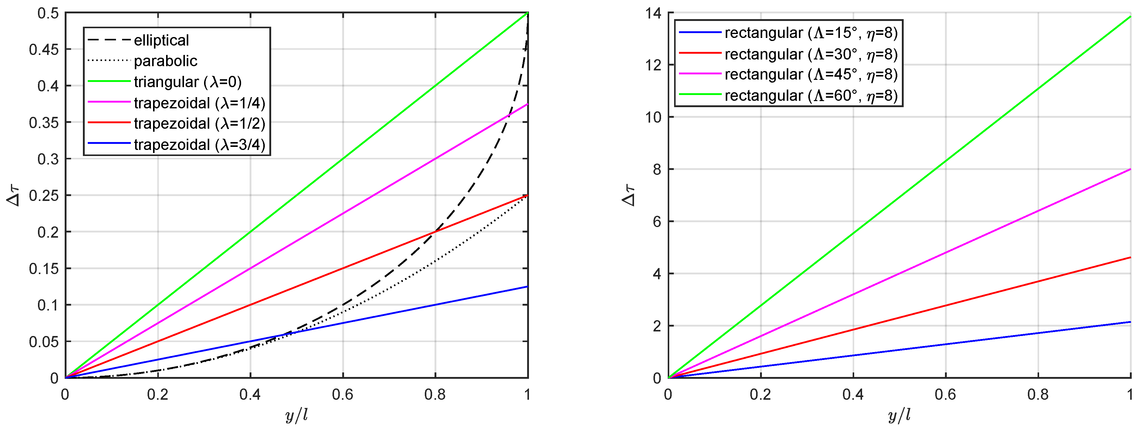
When the gust front is (more realistically) normal to the free-stream [65,66], spanwise penetration effects must be considered as the perturbation hits the wing sections at different times Δ τ ( y ) while impinging on a progressive portion ι ( τ ) of the span from root to tip [99]. The local delay for the sectional load build-up depends on the trailing-edge geometry and the wing’s incipient lift-deficiency coefficient C L ( τ ) may be estimated as:
lim τ 0 C L     f ι l C L , Δ τ   =   1 2 1 c c r   +   4 c r y tan Λ ,
where the impingement factor f represents the fraction of total area covered by the travelling gust that lays between its normal front and the wing’s leading edge. Figure 5 shows the gust penetration delay for all sections along the span of elliptical and trapezoidal wings: while any taper causes a small delay (regardless of the aspect ratio), even a moderate sweep angle generates a significant delay (especially for large aspect ratio).

3.2.1. Elliptical Wings: Curved Taper

The geometrical properties of elliptical wings are:
c   =   c r 1 y 2 l 2 , A   =   π 2 l c r , η   =   8 l π c r , r   =   π 4 ,
and the leading-edge curvature then gives:
τ ¯   =   1 2 , Δ τ   =   τ ¯ 1 1 y 2 l 2 , f   =   π 4 , ι   =   l 1 1 τ τ ¯ 2 , τ τ ¯ ,
with τ ¯ being the time taken by a wind gust with normal front to travel a quarter root chord and impinge the full wing span.
In fact, a parabolic (yet third-order-accurate) approximation is suitable for most of the leading edge towards the wing root, namely:
τ ¯   =   1 4 , lim y 0 Δ τ     τ ¯ y 2 l 2 , f   =   2 3 , lim τ 0 ι     l τ τ ¯ ,
which can conveniently be employed to calculate the incipient indicial lift as:
lim τ 0 C ˇ L     8 2 3 e τ α , τ < 9 64 ,
within the reduced time taken by C ˇ L to grow with the same rate as C ˇ L , the wing sections towards the tips (where the airload drops rapidly) giving little contribution anyway [65].

3.2.2. Trapezoidal Wings: Swept Taper

The geometrical properties of trapezoidal wings are:
c   =   c r 1 1 λ y l , A   =   1   +   λ l c r , η   =   4 l 1   +   λ c r , r   =   1   +   λ 2 ,
and the leading-edge rotation due to both sweep angle (with reference to the quarter-chord line along the span, where sectional aerodynamic centres lay) and chord taper then gives:
τ ¯   =   1 2 1 λ   +   1   +   λ η tan Λ , Δ τ   =   τ ¯ y l , f   =   1 2 , ι   =   l τ τ ¯ , τ τ ¯ ,
which can be employed to calculate the incipient indicial lift as:
lim τ 0 C ˇ L     2 τ e τ ¯ τ α cos Λ , τ < min 2 τ ¯ 3 , 2 ,
confirming previous theoretical studies [99], still within the reduced time taken by C ˇ L to grow with the same rate as C ˇ L while the wing’s outboard sections give little contribution [66].

4. Compressible Potential Flow: Acoustic Wave Theory

Due to the intrinsic similarity between the governing equations of incompressible and subsonic compressible fluids in the absence of shock waves [23,61], the circulatory indicial-admittance functions previously obtained for the former case can be generalised for the latter case [73,74,75] as long as Prandtl–Glauert’s analogy holds. In particular, the steady airload derivatives for thin airfoils are divided by β [18,19], while the reduced time for the unsteady airload development is scaled by β 2 [20]; the airstream being identically unperturbed ahead of the aerofoil, the initial circulatory lift coincides in both compressible and incompressible flows [4]. In the presence of sweep, the Mach number is effectively scaled by cos Λ and Prandtl–Glauert’s compressibility factor changes accordingly [144,145]:
C ¯ l / α = 2 π β ´ cos Λ , β ´ = 1 M ´ 2 , M ´ = M cos Λ , U ´ = U cos Λ ,
where the steady lift coefficient of the isolated sections C ¯ l / α include most of the effects from wing sweep and flow compressibility already [11], whereas the steady lift and circulation coefficients of the entire wing include the influence of the steady downwash too (see Appendix A). As mentioned, the accuracy of such an approximation depends on the rigorous applicability of the underlying fluid mechanics similitude and deteriorates with increasing Mach number towards the transonic regime [62]; yet, Kelvin’s and Stokes’ theorems for the conservation of total null circulation on all streamlines along closed paths hold for isentropic potential flow as well [24], along with Kutta’s condition for the unloaded trailing edge [82,83]. Thus, by taking advantage of Maclaurin’s expansion at small times, the wing’s incipient lift coefficient may generally be written as:
lim τ 0 C L     C l / α α α i , lim τ 0 α i     2 e g τ α cos Λ ,
where the downwash angle α i ( τ ) lowers the unsteady airload and the two-dimensional one is correctly recovered in the limit of infinitely slender wing [76] (i.e., with g = 0 ); still, nonlinear terms have coherently been neglected and likewise the related incipient downwash α i ( τ ) from a vertical sharp-edged gust. Focusing on the subsonic regime of an irrotational flow without shock waves (i.e., with M ´ < 0.6 ), note that higher-order effects from fluid compressibility on the incipient downwash have also been disregarded [51,129,130], as the spanwise (low-speed) vorticity develops normal to the free-stream.
Alternative approaches [146,147,148,149,150,151,152,153] have been proposed that involve the definition of an acceleration potential function as the substantial derivative of the kinetic potential function, the former being governed by the same aero-acoustic equation of the latter [24]; a kernel function for unsteady subsonic flow is often involved [118,119,124]. However, with the aerofoil being represented by a sheet of acceleration potential doublets exploiting the analytical solution for a source pulse (where disturbance pressure and doublets strength are directly proportional) and producing a pressure discontinuity [23], they pertain harmonic motion and their inherent complexity (also in terms of auxiliary boundary conditions) is not practical [154].

4.1. Thin Aerofoils: Two-Dimensional Acoustic Waves Propagation and Chordwise Gust Penetration

With respect to a coordinate system moving with the sound speed in air at rest (i.e., with ς = a t ), the incipient indicial lift-coefficient from a step in the angle of attack may be computed by analogy with steady flow [23,24]:
2 ϕ   =   2 ϕ ς 2 , ϕ z s s , ς   =   U α , p   +   ρ a ϕ ς   =   p ,
where each wing section s s translates backwards from its actual position along the wing with velocity U, with leading and trailing edges displaced by Δ x L E   =   M ς and Δ x T E   =   c M ς , respectively. At the same time, the flow disturbances due to the sudden motion of the wing chord propagate from the latter as a series of circles with centres along the chord c itself and instantaneous radii equal to ς ; thus, the resulting foremost and rearmost Mach cones have vertices along the Mach lines Δ x F C   =   ± ς and Δ x R C   =   c ± ς (i.e., where the foremost and rearmost expanding circles cut the wing plane), respectively. The pressure discontinuity vanishing off the wing planform, Kutta’s condition still holds at the trailing edge of each wing section [17]. In particular, the very start of the indicial flow response on the latter is equivalent to considering a piston impulsively moved with normal velocity U α into air at rest, namely [23,24]:
2 ϕ z 2   =   1 a 2 2 ϕ t 2 , lim t 0 Δ p = 2 ρ a U α , lim t 0 C l   =   4 α M ,
where the particular solution ϕ s a t satisfies the impermeability boundary conditions and propagates according to acoustic wave theory [59], Δ p ( t ) is the difference between the flow pressure on upper and lower surfaces of the aerofoil (which is scaled by cos Λ in the presence of sweep), and the instantaneous centre of pressure is initially at midchord [4].
Within the reduced times τ ^ and τ ˇ taken by the outgoing and incoming waves to travel the section chord with speed U ´   +   a and U ´ a [20], respectively, the characteristic lines intersect [15,17] and the initial lift developments from a step in the angle of attack and a sharp-edged gust are then found as [66]:
C l   =   4 α M 1 1 M ´ 2 M ´ τ , C l   =   2 τ α M ´ cos Λ , τ 2 M ´ 1   +   M ´ ;
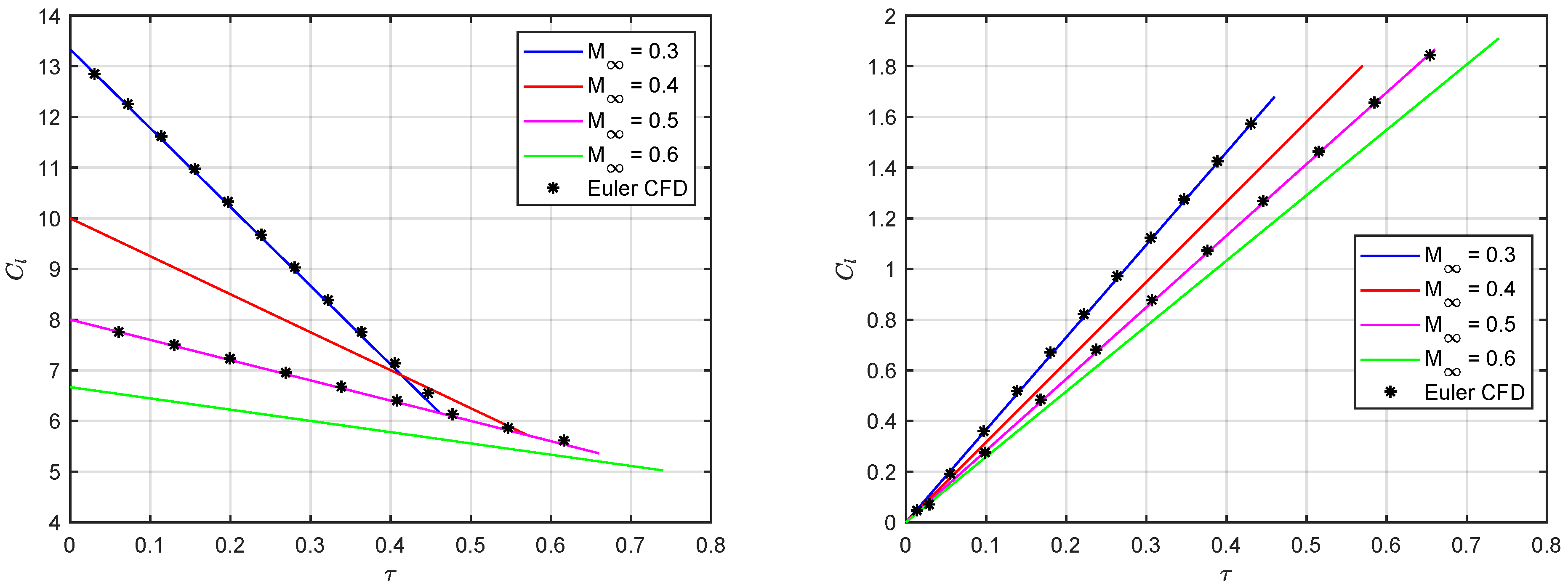
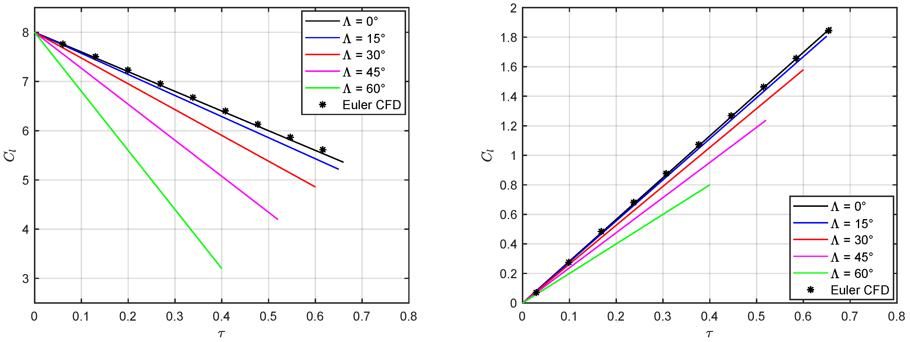
the aerodynamic centre starts at midchord and leading edge in the former and latter cases [4], eventually moving to the quarter-chord where the circulatory airload acts [20]. As the aerofoil chord is also effectively scaled by cos Λ , note that the reduced time is independent of the sweep angle [23,24]. Figure 6 compares the exact incipient lift coefficient from a step in the angle of attack and a sharp-edged gust with Euler-based CFD simulations available in the literature [64] for a NACA0002 aerofoil [155] aligned with the unperturbed flow at different subsonic Mach numbers (i.e., for 0.3 M 0.6 ) and α   =   1 ; perfect agreement is always found for τ < τ ^ . Figure 7 then shows the effect of a sweep angle, which is not simply proportional to the cos Λ projection and has lower impact on the lift from a sharp-edged gust due to the variation in the effective Mach number M ´ .
In the singular limit of incompressible flow, as mentioned, the non-circulatory terms degenerate into a Dirac-delta [94] centred at the perturbation onset and give rise to unsteady loads from apparent fluid inertia centred at the aerofoil mid-chord [133]. As for the circulatory contribution to the unsteady airload, it is worth mentioning that the related indicial-admittance functions have been generalised for compressible subsonic flow, exploiting Prandtl–Glauert’s transformation [18,19] in the absence of shock waves [20,64], and depict the flow response at later times (i.e., for τ > τ ˇ ) until steady conditions are eventually reached. An exact theoretical solution also exists in the transition region [17] (i.e., for τ ^ < τ < τ ˇ ), but its cumbersome analytical expression is of little practical use.

4.2. Thin Wings: Three-Dimensional Downwash Angle, Spanwise Gust Penetration, and Mean Wing Section

In order to calculate the wing’s incipient lift coefficient, the contribution of all sections must be considered. Referring to the mean geometric one according to the mean-value theorem, acoustic wave results [4] are then modified to account for three-dimensional effects [65,66] and approximate the initial non-circulatory lift from a step in the angle of attack or a vertical sharp-edged gust as:
C L     4 α M 1 1 M ´ 2 r M ´   +   2 e g cos Λ τ , C L     2 τ α r M ´ cos Λ , τ 2 r M ´ 1   +   M ´ ,
respectively, where higher-order terms and nonlinear compressibility effects have been discarded [51,129,130]; still, spanwise gust penetration effects are not yet included.

4.2.1. Elliptical Wings: Curved Taper

For a vertical sharp-edged gust with a normal front, the incipient lift of an elliptical wing is estimated as:
C L     2 α τ M 1 1 2 τ 2 , τ min π M 2 1   +   M , 1 2 ,
as long as acoustic wave theory remains applicable for all impinged sections, within the reduced time taken by the gust to cover the entire wing span; due to the latter effect, the derived wing’s lift growth starts (highly) nonlinearly but does become (quasi) linear as full-span impingement is progressively approached.
Alternatively, adopting a parabolic approximation for the leading edge gives:
C L     32 α τ τ 3 π M 0 τ min π M 2 1   +   M , 1 4 , 8 α π M τ 1 12 min π M 2 1   +   M , 1 4 τ π M 2 1   +   M ,
within the reduced time taken by C L to grow with the same rate as C L , while acoustic wave theory remains applicable for all impinged sections; the effective delay introduced by the spanwise penetration is then seen to be rather small, especially with respect to that introduced by the chordwise penetration. When τ ¯ < 2 τ ^ , note that the derived wing’s lift growth switches from nonlinear to linear at half of the exact full-span impingement time τ ¯ for an elliptical leading edge (recall Figure 5).

4.2.2. Trapezoidal Wings: Swept Taper

For a vertical sharp-edged gust with normal front, the incipient lift of a trapezoidal wing is estimated as:
C L     τ 2 α τ ¯ r M ´ cos Λ 0 τ min 2 r M ´ 1   +   M ´ , τ ¯ , 2 α r M ´ τ τ ¯ 2 cos Λ min 2 r M ´ 1   +   M ´ , τ ¯ τ 2 r M ´ 1   +   M ´ ,
as long as acoustic wave theory remains applicable for all impinged sections, still within the reduced time taken by C L to grow with same rate as C L ; at later times, the circulatory contribution becomes progressively predominant, and the effective delay introduced by the spanwise penetration is seen to be rather large in the presence of significant sweep. When τ ¯ < τ ^ , note that the derived wing’s lift growth does switch from nonlinear to linear at the full-span impingement time τ ¯ ; moreover, the exact solution for a two-dimensional section is automatically recovered for straight rectangular wings (i.e., with Λ 0 , r 1 and τ ¯ 0 ) of any aspect ratio, since the gust front is parallel to the leading edge and higher-order downwash effects are fairly neglected.

5. Results and Discussion

The proposed analytical method is assessed for the effects of the flow’s Mach number as well as the wing’s aspect ratio, tapered curvature, and sweep angle on the incipient unsteady airload from a step in the angle of attack and a vertical sharp-edged gust; both elliptical [65] and trapezoidal [66] wings are investigated. The approximate theoretical results are supported by available high-fidelity data from nonlinear Euler-based CFD simulations, which underwent rigorous convergence studies for both spatial and temporal resolutions; all details of the numerical models and computations can be found in the original works directly [65,66], from geometrical features and grid arrangement to boundary conditions and integration scheme as well as flow perturbation treatment.
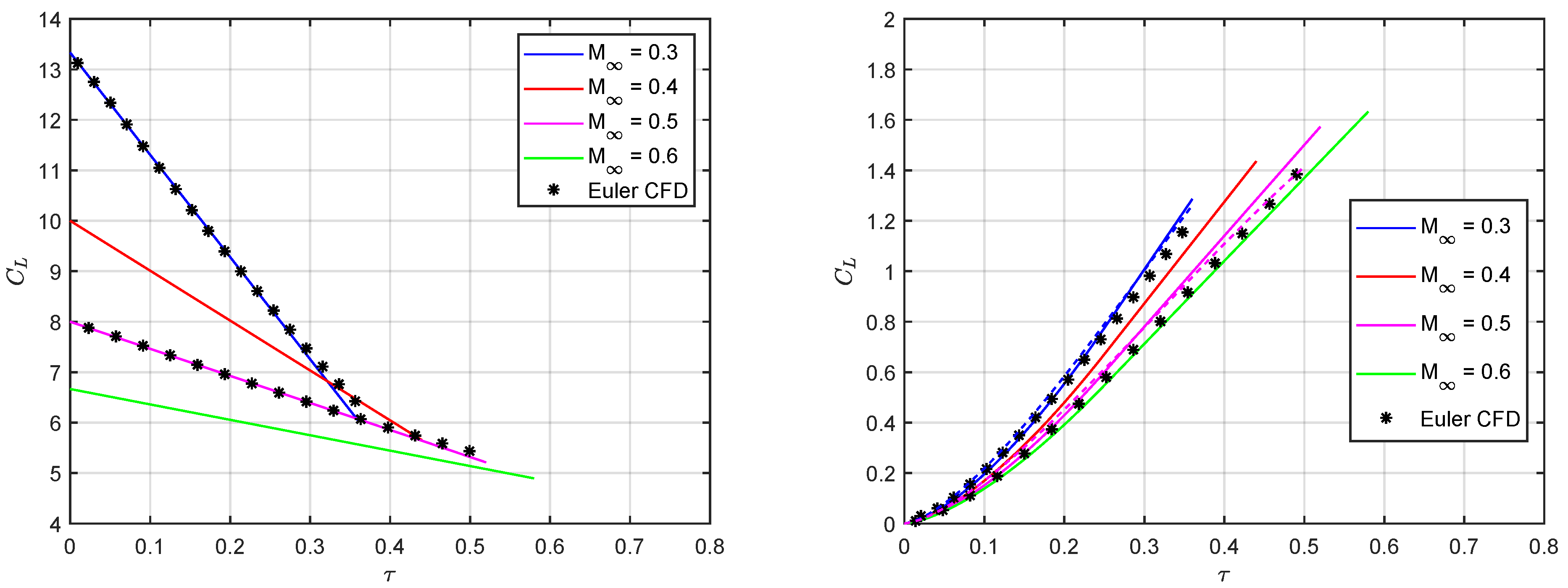
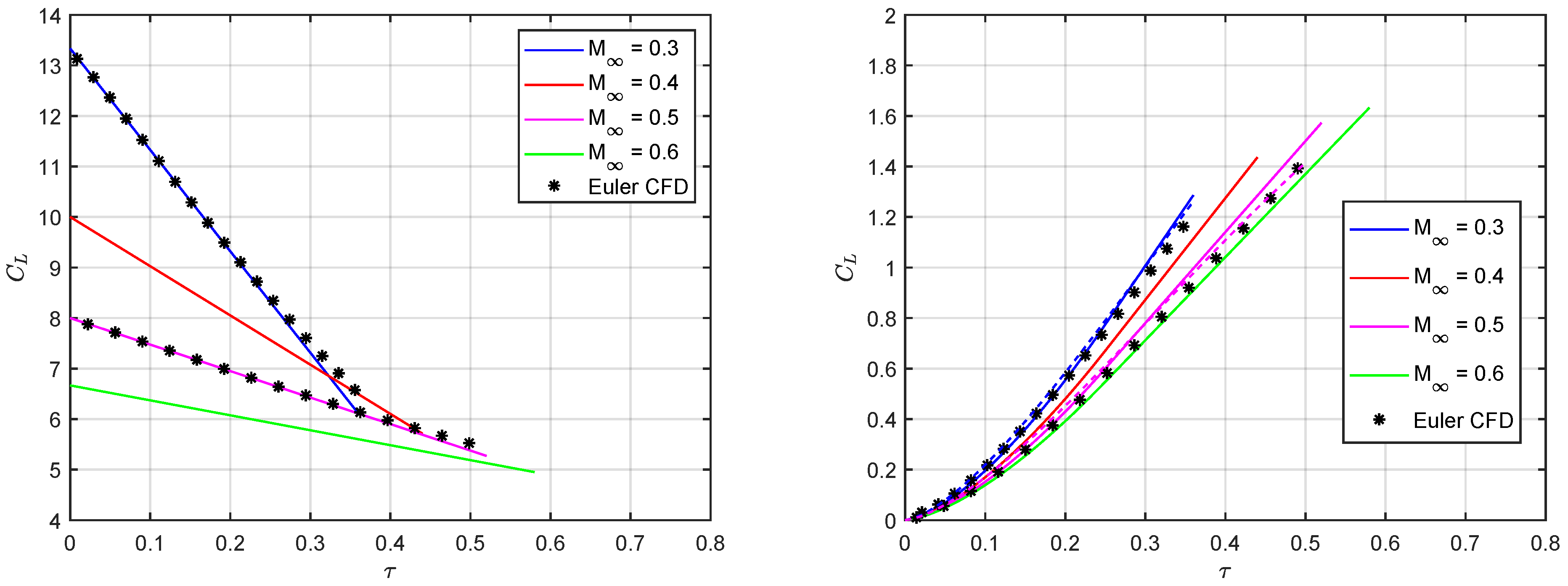
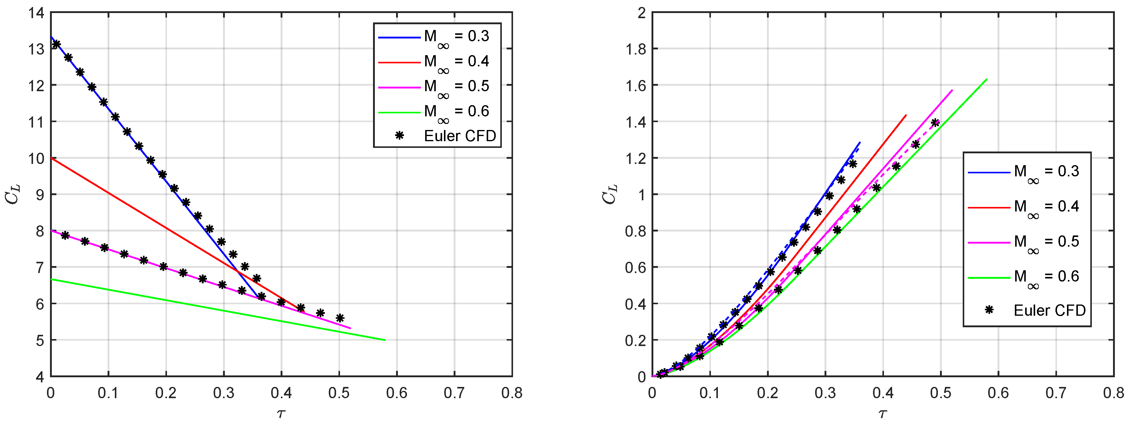
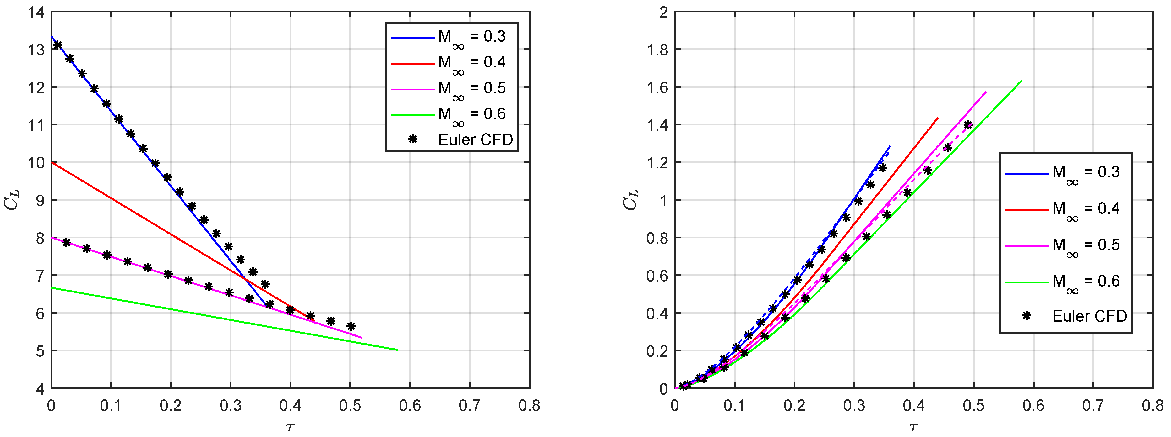
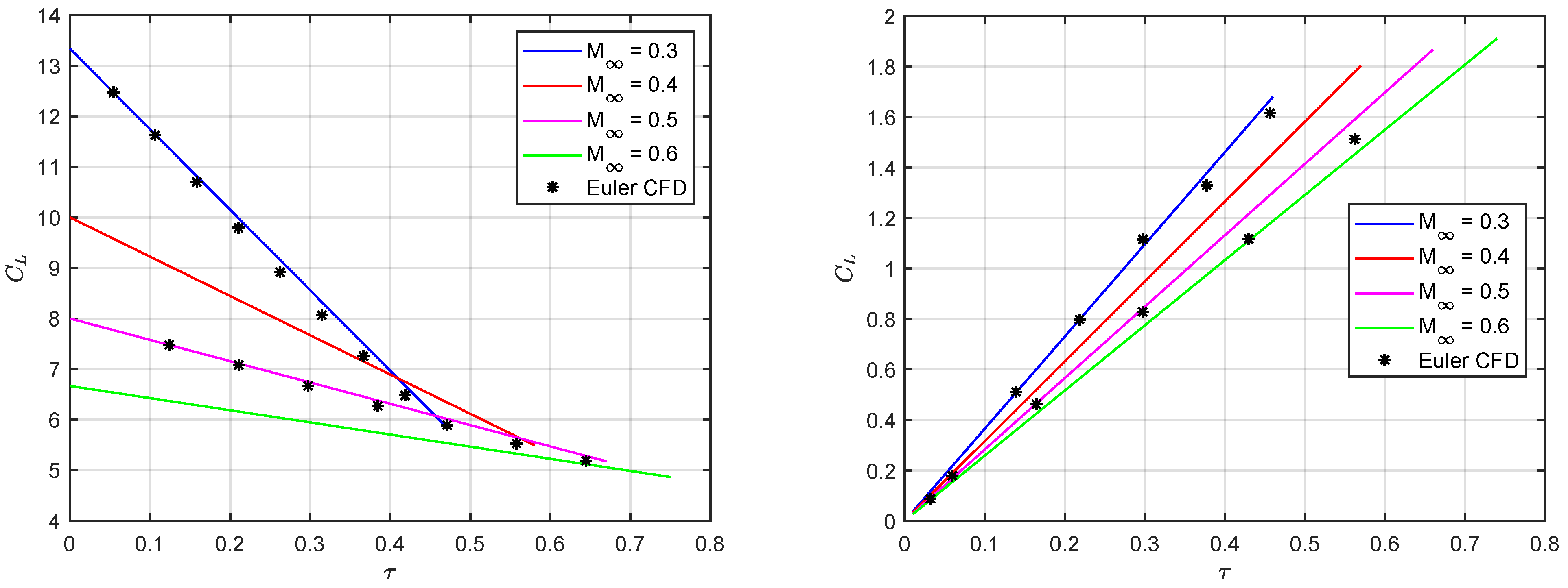
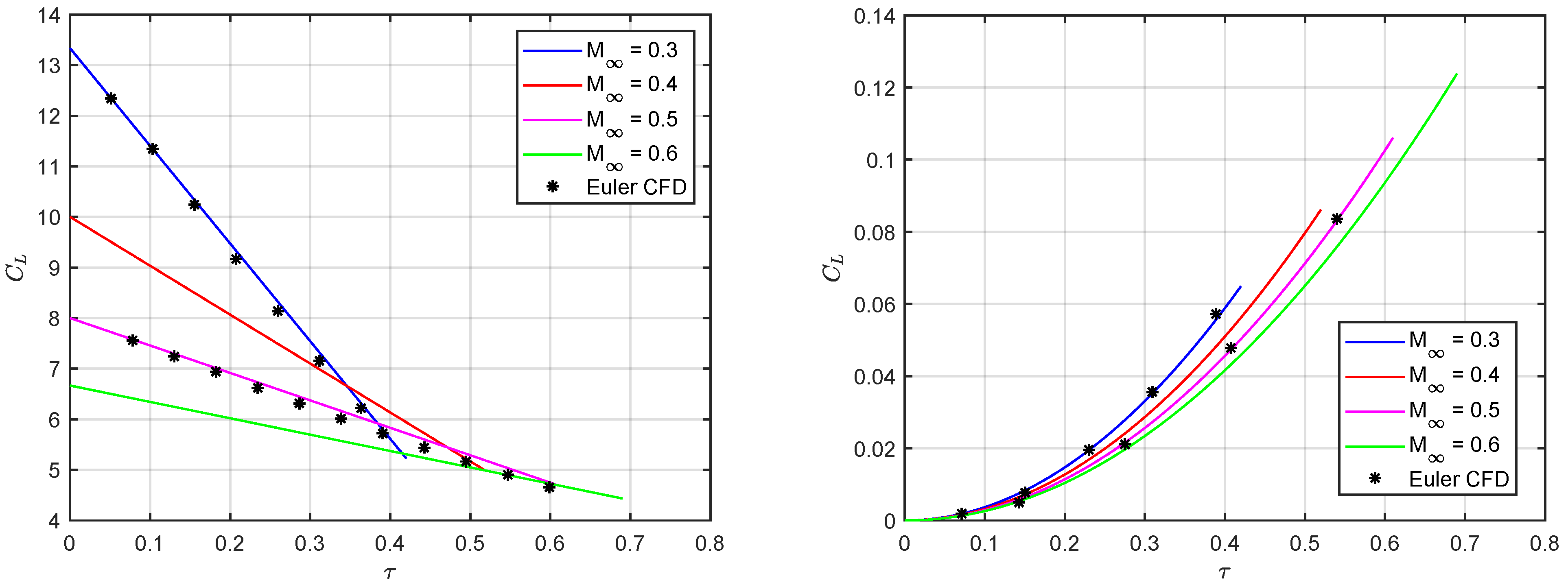
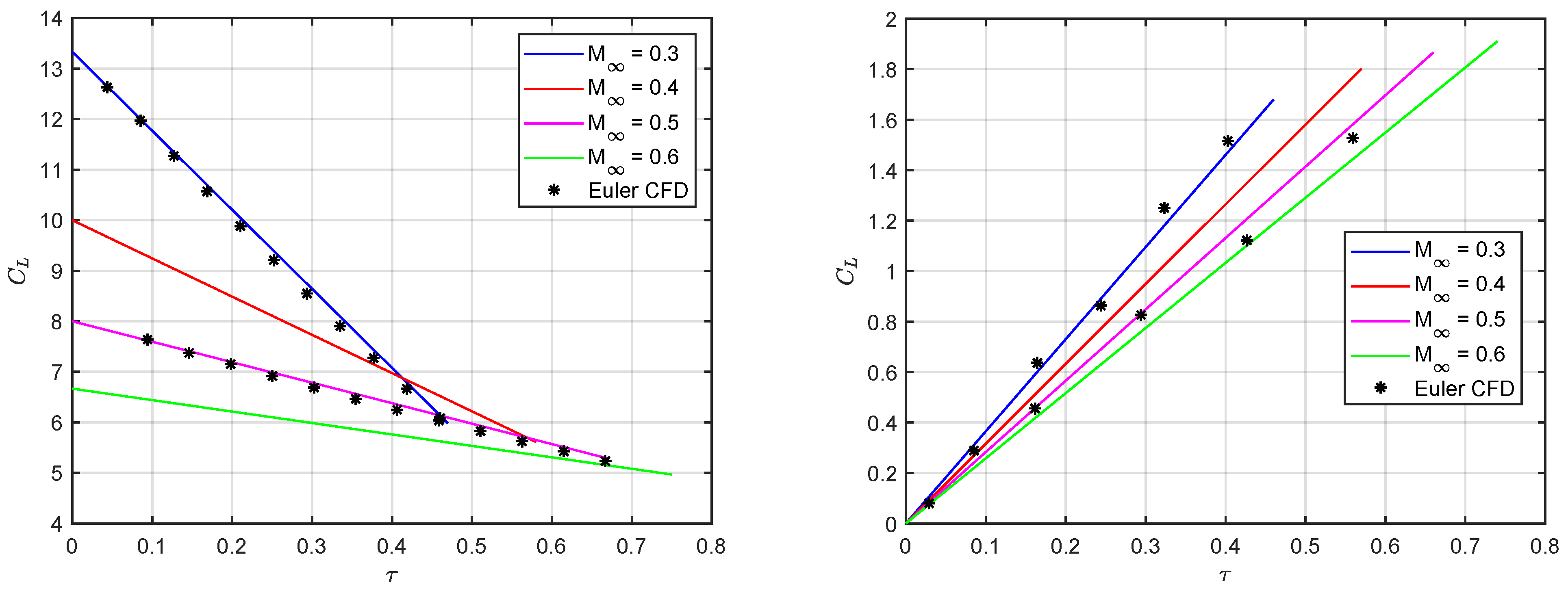
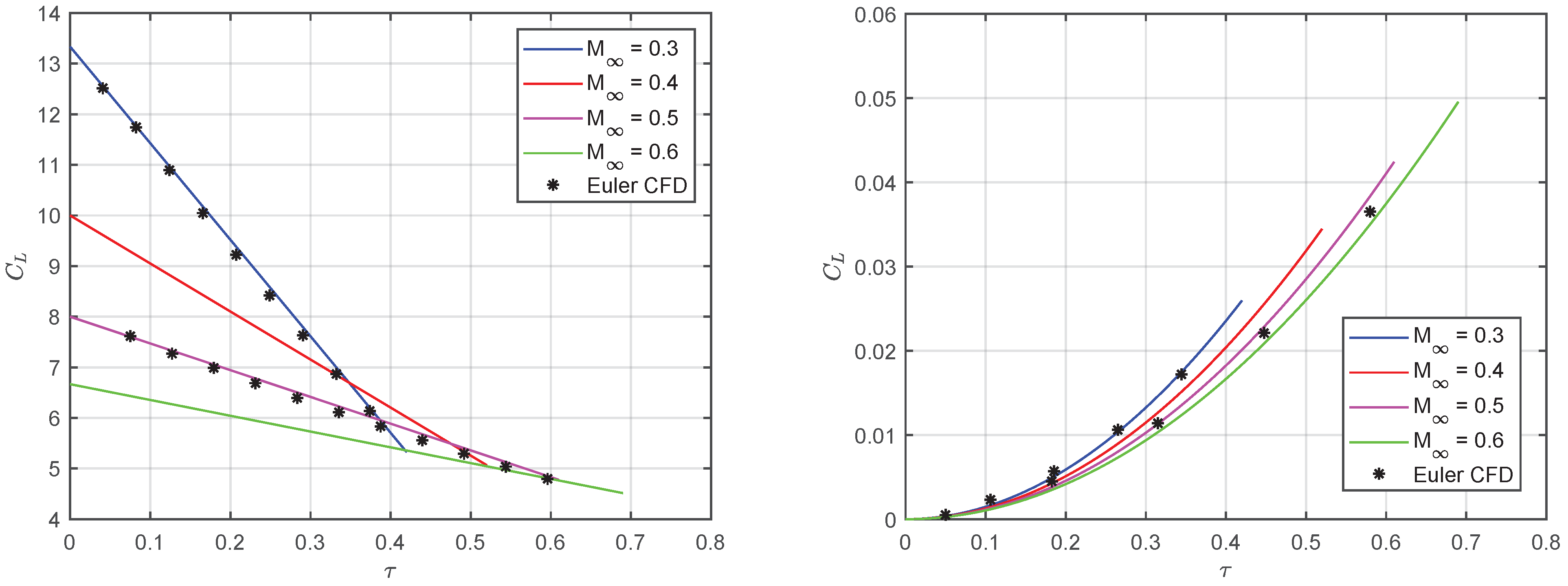
Considering an elliptical wing with NACA0002 aerofoil [155] aligned with the unperturbed flow and α = 1 , Figure 8, Figure 9, Figure 10 and Figure 11 compare the present parametric analytical approximation with Euler-based CFD simulations available in the literature [65] for several subsonic Mach numbers (i.e., for 0.3 M 0.6 ) and wing’s aspect ratios (i.e., for 6 η 20 ): excellent agreement is always found without any tuning (i.e., with κ = 1 ). For the incipient lift from a sharp-edged gust, the latter covers the full wingspan while acoustic wave theory remains applicable for all impinged sections only in the case of the two higher Mach numbers (i.e., for M 0.5 ). The analytical predictions feature a parabolic approximation of the wing’s leading edge and tend to grow slightly faster than the CFD solution as time passes, because they conservatively neglect higher-order effects in both downwash angle (less important) and leading-edge curvature (more important); theoretical predictions featuring an elliptical leading edge are also shown by the dashed lines in the figures, for the sake of assessment and completeness. In all cases, the effect of considering the mean geometric chord is found to be much larger than the effect of accounting for the downwash angle (as confirmed by nearly identical results obtained at the same Mach numbers for the incipient lift from a step in the angle of attack of a trapezoidal straight wing with the same area and aspect ratio [65]).
Considering a rectangular wing with η = 8 as well as NACA0006 aerofoil [155] aligned with the unperturbed flow and α = 1 , Figure 12, Figure 13, Figure 14 and Figure 15 compare the present parametric analytical approximation with Euler-based CFD simulations available in the literature [66] for different subsonic Mach numbers (i.e., for 0.3 M 0.6 ) and sweep angles (i.e., for 0 Λ 30 ): still, excellent agreement is always found without any tuning (i.e., with κ = 1 ). Due to the rectangular planform (i.e., λ = 1 ), considering the mean geometric chord has no effect whereas accounting for the downwash angle lowers the slope of the incipient lift from a step in the angle of attack, especially for the lower aspect ratio; however, the impact of a significant sweep angle is found to be largely predominant. For the incipient lift of the straight wings from a sharp-edged gust, the perturbation front is parallel to the leading edge and the analytical results depict the exact linear solution for a two-dimensional section, as nonlinear downwash effects are fairly neglected regardless of the aspect ratio. For the incipient lift of the swept wings from a sharp-edged gust, the latter cannot yet cover the full wing span while acoustic wave theory remains applicable for all impinged sections, and this prevents the analytical approximation from depicting a linear growth of the lift coefficient; still, higher-order terms are confirmed to be marginal during chordwise penetration.
Given its rigorous derivation and all successful comparisons above, the proposed theoretical model may reliably be used to derive the correct initial behaviour of the wing’s lift build-up, whenever approximated with a convenient combination of parametric exponential and trigonometric functions [64,65,66].

6. Conclusions

Explicit analytical corrections for the unsteady downwash and enhanced approximate expressions for the incipient indicial lift of thin wings in the subsonic regime have been presented in this study, considering a step-change in the angle of attack or a vertical sharp-edged gust as the unsteady flow perturbation within a unified formulation. Both linear and nonlinear geometrical effects from taper ratio, leading-edge curvature, and sweep angle have been investigated and were found to be significant for elliptical and rectangular wings, accounting for the chordwise and spanwise penetration of the gust while adopting the lifting-line model and acoustic wave theory within a consistent parametric framework for potential flow. At the beginning of the aero-acoustic response, nonlinear effects from flow compressibility as well as two-dimensional (chordwise) inflow and three-dimensional (spanwise) downwash developments are coherently shown to be marginal, especially for the case of a travelling gust; however, linear downwash and compressibility corrections remain crucial for the circulation growth at later times. The initial build-up of the wing lift is then estimated with explicit analytical expressions, which provide sound insights for practical validation purposes and may serve to assess the unavoidable trade-off between detailed complexity and computational costs of higher-fidelity tools in the aviation industry. The derived formulae have successfully been evaluated against numerical results in the literature for fundamental aerodynamic indicial-admittance functions, demonstrating effective theoretical and computational synthesis of the governing physics. The present model is hence suggested for use within multifidelity multidisciplinary aeroplane design and optimisation as an efficient reduced-order model to calculate incipient wing airloads and quantify their uncertainties and sensitivities with respect to aerodynamic parameters.

Funding

This research received no external funding.

Conflicts of Interest

The author declare no conflict of interest.

Acronyms

AOAAngle of Attack
CFDComputational Fluid Dynamics
FSIFluid–Structure Interaction
MDOMultidisciplinary Design Optimisation
PDEPartial Differential Equation
ROMReduced-Order Model
SEGSharp-Edged Gust

Symbols

asound speed
Awing area
B n 1 Bessel’s functions of first type and n-th order
cwing section chord
c p isobaric heat capacity
c v isochoric heat capacity
C γ wing section circulation coefficient
C γ / α wing section circulation derivative
C Γ wing circulation coefficient
C Γ / α wing circulation derivative
C l wing section lift coefficient
C l / α wing section lift derivative
C L wing lift coefficient
C L / α wing lift derivative
C p pressure coefficient
C E Sears’s circulation-deficiency function
C S Sears’s lift-deficiency function
C T Theodorsen’s lift-deficiency function
eedge-velocity factor
Eairflow internal energy
fwing area impingement factor
gdownwash gradient factor
Hairflow enthalpy
H n 2 Hankel’s functions of second type and n-th order
Icomplete elliptic integral of the second kind
kreduced frequency
lwing semi-span
MMach number
n normal vector
Nexpansion terms
pairflow pressure
rmean chord ratio
Rgas constant
snon-dimensional elliptic integral argument
s space vector
Sairflow entropy
ttime
Tairflow temperature
Uhorizontal free-stream
xchordwise coordinate
yspanwise coordinate
zvertical coordinate
Greek
α angle of attack
β airflow compressibility factor
ϕ airflow disturbance potential
φ airflow velocity potential
η wing aspect ratio
κ shape factor (downwash tuning)
γ airflow heat capacity ratio
Γ wing section circulation
ι wing span impingement fraction
λ wing taper ratio
Λ sweep angle
ν airflow velocity vector
ψ spanwise angle
ρ airflow density
ς sound-travelled distance
τ reduced time
υ non-dimensional wake development
ω angular frequency
ω airflow vorticity vector
Superscripts
χ angle of attack step
χ gust front parallel to leading edge
χ gust front normal to reference airspeed
χ ´ airflow normal to aerodynamic axis
χ ˇ circulatory
χ ^ non-circulatory
χ ¯ steady
Subscripts
χ a average
χ F C foremost cone
χ G gust
χ i induced
χ L E leading edge
χ r root
χ R C rearmost cone
χ s section
χ t tip
χ T E trailing edge
χ w wing
χ 0 initial
χ unperturbed

Appendix A

Starting from a simplified lifting-surface equation for the wing’s steady circulation Γ ¯ ( y ) [156,157,158,159] and considering the average distance between aerodynamic centres and control points [160], an enhanced lifting-line model was obtained as [51]:
Γ ¯ 1 + 4 η 2   +   c 4 l   +   l d Γ ¯ d ζ d ζ y ζ   =   U 2 c C ¯ l , α ¯ i   =   1 4 π U l   +   l d Γ ¯ d ζ d ζ y ζ ,
where C ¯ l is the steady lift coefficient of the isolated wing section; a better estimation of the steady downwash α ¯ i ( y ) is mainly obtained towards the wing root, but sections towards the wing tips give little airload contribution anyway [10,23]. Note that e η 4   +   η 2 for elliptical planforms with η > 4 [140], in agreement with the proposed unsteady model within a unified formulation.
Due to Glauert’s integral (in principal value) with Γ ¯ ± l   =   0 at the wing tips [78], Prandtl’s expansion gives [76]:
Γ ¯     l U n   =   1 N Γ Γ ¯ n sin n ψ , α ¯ i     n   =   1 N Γ n Γ ¯ n sin n ψ 4 sin ψ , C ¯ L   =   π 4 η Γ ¯ 1 ,
and hence an algebraic system of linear equations for the enhanced lifting-line model [51]:
n   =   1 N Γ Γ ¯ n sin n ψ 1   +   4 η 2   +   n c C ¯ l / α 8 l sin ψ   =   c C ¯ l 2 l ,
where the unknown coefficients Γ ¯ n may be found via the least-squares method [161], considering at least N Γ sections along the wing span (i.e., y   =   l cos ψ with 0 ψ π running from tip to tip); still, the steady lift coefficient of the wing C ¯ L depends on the first coefficient only, whereas all other terms modify the airload distribution without altering its integral [10]. Note that the singularity at the wing tips can be lifted by multiplying both sides of the equation by sin ψ , and Prandtl’s original equations [76] are asymptotically resumed for very slender wings (i.e., with e   =   1 ); odd and even Fourier terms give symmetric and antisymmetric airload distributions, respectively, [23]. Finally, the shape factor κ introduces higher-order deviations [162,163] from the ideal elliptic case (i.e., with N Γ   =   1 and κ   =   1 ), namely:
Γ ¯   =   U 2 c C ¯ L , α ¯ i   =   κ C ¯ L π η , C ¯ L / α   =   π η C ¯ l / α π e η   +   κ C ¯ l / α ,
where C ¯ L / α and C ¯ l / α are the steady lift coefficient derivatives of the entire wing and its isolated section (which may include thickness effects from conformal mapping [14,164]); of course, the larger the deviations the lower the aerodynamic efficiency and the higher the shape factor (especially at higher aspect ratios).
Although different implementations and alternative approaches have long been proposed [165,166,167,168,169,170,171,172], note that lifting-line theory is still the subject of recent studies and generalisations [173,174,175,176,177,178,179,180] due to its essential clarity, as powerful aerodynamic tool for wings in steady subsonic flow [181].

Appendix B

The fundamental indicial-admittance functions for the unsteady airload of isolated two-dimensional sections in incompressible potential flow may rigorously be derived in the reduced time τ domain from corresponding impulsive transfer functions in the reduced frequency k domain [182,183,184]; note that also the latter is independent of the sweep angle [23]. For the case of a step in the angle of attack, the derivatives of the indicial lift-deficiency and circulation-deficiency coefficients may be written as [23]:
C ˇ l / α   =     +   C T i k e i k τ d k , C T   =   H 1 2 H 1 2   +   i H 0 2 , k   =   c r ω 2 U ,
C ˇ γ / α   =     +   C S i k e i k τ d k , C S   =   B 0 1 i B 1 1 C T   +   i B 1 1 e i k ,
where C T k and C S k are Theodorsen’s [133] and Sears’ [134] functions, respectively, H n 2 ( k ) are Hankel functions of the second type and n-th order, B n 1 ( k ) are Bessel functions of the first type and n-th order, and ω is the angular frequency of the flow perturbation. For the case of a vertical sharp-edged gust, the derivative of Wagner’s [131] indicial circulation-deficiency coefficient for a step in angle of attack coincides with that of Kussner’s [132] indicial lift-deficiency coefficient (i.e., just C ˇ l / α C ˇ γ / α ), while the derivative of the indicial circulation-deficiency coefficient may be written as [88]:
C ˇ γ / α   =     +   C E i k e i k τ d k , C E   =   B 0 1 i B 1 1 C S e i k ,
where the complex function C E k embeds a further travelled semichord delay [93,135].
It is worth stressing that these fundamental indicial-admittance functions are also still the subject of recent studies and generalisations [185,186,187,188,189,190,191,192,193,194,195,196,197,198,199,200,201,202,203] due to their essential clarity, as powerful aerodynamic tools for thin wings in unsteady subsonic flow [204,205,206].

References

  1. Alexandrov, N.; Hussaini, M. Multidisciplinary Design Optimization: State of the Art; SIAM: Philadelphia, PA, USA, 1997. [Google Scholar]
  2. Martins, J.; Lambe, A. Multidisciplinary Design Optimization: A Survey of Architectures. AIAA J. 2013, 51, 2049–2075. [Google Scholar] [CrossRef] [Green Version]
  3. Tobak, M. On the Use of the Indicial-Function Concept in the Analysis of Unsteady Motions of Wings and Wing-Tail Combinations. In NACA-TR-1188; NACA: Washington, DC, USA, 1954. [Google Scholar]
  4. Lomax, H. Indicial Aerodynamics. In Manual on Aeroelasticity; AGARD-R-578-71; AGARD: London, UK, 1971. [Google Scholar]
  5. Quarteroni, A.; Rozza, G. Reduced Order Methods for Modeling and Computational Reduction; Springer International Publishing: Cham, Switzerland, 2014. [Google Scholar]
  6. Silva, W. AEROM: NASA’s Unsteady Aerodynamic and Aeroelastic Reduced-Order Modeling Software. Aerospace 2018, 5, 41. [Google Scholar] [CrossRef] [Green Version]
  7. Livne, E. Integrated Aeroservoelastic Optimization: Status and Direction. J. Aircr. 1999, 36, 122–145. [Google Scholar] [CrossRef]
  8. Livne, E. Future of Airplane Aeroelasticity. J. Aircr. 2003, 40, 1066–1092. [Google Scholar] [CrossRef]
  9. Stanford, B.K. Role of Unsteady Aerodynamics During Aeroelastic Optimization. AIAA J. 2015, 53, 3826–3831. [Google Scholar] [CrossRef]
  10. Katz, J.; Plotkin, A. Low Speed Aerodynamics; Cambridge University Press: Cambridge, UK, 2001. [Google Scholar]
  11. Anderson, J.D. Fundamentals of Aerodynamics; McGraw-Hill: New York, NY, USA, 2007. [Google Scholar]
  12. NOAA. U.S. Standard Atmosphere. In NOOA-S/T 76-1562; NASA: Washington, DC, USA, 1976. [Google Scholar]
  13. LeVeque, R.J. Numerical Methods for Conservation Laws; Springer: Basel, Switzerland, 1992. [Google Scholar]
  14. Karamcheti, K. Principles of Ideal-Fluid Aerodynamics; Wiley: New York, NY, USA, 1967. [Google Scholar]
  15. Thornhill, C.K. The Numerical Method of Characteristics for Hyperbolic Problems in Three Independent Variables. In ARC-RM-2615; ARC: London, UK, 1952. [Google Scholar]
  16. Lomax, H.; Heaslet, M.A. The Indicial Lift and Pitching Moment for a Sinking or Pitching Two-Dimensional Wing Flying at Subsonic or Supersonic Speeds. In NACA-TN-2403; NACA: Washington, DC, USA, 1951. [Google Scholar]
  17. Lomax, H.; Heaslet, M.A.; Fuller, F.D.; Sluder, L. Two- and Three-Dimensional Unsteady Lift Problems in High-Speed Flight. In NACA-TR-1077; NACA: Washington, DC, USA, 1952. [Google Scholar]
  18. Glauert, H. The Effect of Compressibility on the Lift of an Aerofoil. Proc. R. Soc. Lond. Ser. A 1928, 118, 113–119. [Google Scholar]
  19. Gothert, B.H. Plane and Three-Dimensional Flow at High Subsonic Speeds. In NACA-TM-1105; NACA: Washington, DC, USA, 1946. [Google Scholar]
  20. Leishman, J. Principles of Helicopter Aerodynamics; Cambridge University Press: Cambridge, UK, 2006. [Google Scholar]
  21. Heaslet, M.A.; Lomax, H.; Spreiter, J.R. Linearized Compressible-Flow Theory for Sonic Flight Speeds. In NACA-TR-956; NACA: Washington, DC, USA, 1950. [Google Scholar]
  22. Bendiksen, O.O. Review of Unsteady Transonic Aerodynamics: Theory and Applications. Prog. Aerosp. Sci. 2011, 47, 135–167. [Google Scholar] [CrossRef]
  23. Bisplinghoff, R.; Ashley, H.; Halfman, R. Aeroelasticity; Dover: Mineola, NY, USA, 1996. [Google Scholar]
  24. Bisplinghoff, R.; Ashley, H. Principles of Aeroelasticity; Dover: Mineola, NY, USA, 2013. [Google Scholar]
  25. Mazelsky, B. Numerical Determination of Indicial Lift of a Two-Dimensional Sinking Airfoil at Subsonic Mach Numbers from Oscillatory Lift Coefficients with Calculations for Mach Number 0.7. In NACA-TN-2562; NACA: Washington, DC, USA, 1951. [Google Scholar]
  26. Mazelsky, B. Determination of Indicial Lift and Moment of a Two-Dimensional Pitching Airfoil at Subsonic Mach Numbers from Oscillatory Coefficients with Numerical Calculations for a Mach Number of 0.7. In NACA-TN-2613; NACA: Washington, DC, USA, 1952. [Google Scholar]
  27. Mazelsky, B. Numerical Determination of Indicial Lift and Moment Functions for a Two-Dimensional Sinking and Pitching Airfoil at Mach Numbers 0.5 and 0.6. In NACA-TN-2739; NACA: Washington, DC, USA, 1952. [Google Scholar]
  28. Beddoes, T.S. Practical Computation of Unsteady Lift. Vertica 1984, 8, 55–71. [Google Scholar]
  29. Leishman, J.G. Indicial Lift Approximations for Two-Dimensional Subsonic Flow as Obtained from Oscillatory Measurements. J. Aircr. 1993, 30, 340–351. [Google Scholar] [CrossRef]
  30. Leishman, J.G. Subsonic Unsteady Aerodynamics Caused by Gusts Using the Indicial Method. J. Aircr. 1996, 33, 869–879. [Google Scholar] [CrossRef]
  31. Soviero, P.; Hernandes, F. Compressible Unsteady Vortex Lattice Method for Arbitrary Two-Dimensional Motion of Thin Profiles. J. Aircr. 2007, 44, 1494–1498. [Google Scholar] [CrossRef]
  32. Mateescu, D. Theoretical Solutions for Unsteady Compressible Subsonic Flows Past Oscillating Rigid and Flexible Airfoils. Math. Eng. Sci. Aerosp. 2011, 2, 1–27. [Google Scholar]
  33. Lomax, H. Lift Development on Unrestrained Rectangular Wings Entering Gusts at Subsonic and Supersonic Speeds. In NACA-TR-1162; NACA: Washington, DC, USA, 1953. [Google Scholar]
  34. Jones, W.P. Oscillating Wings in Compressible Subsonic Flow. In ARC-RM-2855; ARC: London, UK, 1957. [Google Scholar]
  35. Miranda, I.; Soviero, P. Indicial Response of Thin Wings in a Compressible Subsonic Flow. In Proceedings of the 18th International Congress of Mechanical Engineering, Ouro Preto, Brazil, 6–11 November 2005. [Google Scholar]
  36. Hernandes, F.; Soviero, P. Unsteady Aerodynamic Coefficients Obtained by a Compressible Vortex Lattice Method. J. Aircr. 2009, 46, 1291–1301. [Google Scholar] [CrossRef]
  37. Albano, E.; Rodden, W. A Doublet-Lattice Method for Calculating Lift Distributions on Oscillating Surfaces in Subsonic Flows. AIAA J. 1969, 7, 279–285. [Google Scholar] [CrossRef]
  38. Rodden, W.; Taylor, P.; McIntosh, S. Further Refinement of the Subsonic Doublet-Lattice Method. J. Aircr. 1998, 35, 720–727. [Google Scholar] [CrossRef]
  39. Morino, L. A General Theory of Unsteady Compressible Potential Aerodynamics. In NASA-CR-2464; NASA: Washington, DC, USA, 1974. [Google Scholar]
  40. Morino, L.; Chen, L.; Suciu, E. Steady and Oscillatory Subsonic and Supersonic Aerodynamics around Complex Configurations. AIAA J. 1975, 13, 368–374. [Google Scholar] [CrossRef]
  41. Bindolino, G.; Mantegazza, P. Improvements on a Green’s Function Method for the Solution of Linearized Unsteady Potential Flows. J. Aircr. 1987, 24, 355–361. [Google Scholar] [CrossRef]
  42. Marzocca, P.; Librescu, L.; Kim, D.H.; Lee, I.; Schober, S. Development of an Indicial Function Approach for the Two-Dimensional Incompressible/Compressible Aerodynamic Load Modelling. Proc. Inst. Mech. Eng. Part G J. Aerosp. Eng. 2007, 221, 453–463. [Google Scholar] [CrossRef]
  43. Chung, T. Computational Fluid Dynamics; Cambridge University Press: Cambridge, UK, 2002. [Google Scholar]
  44. Parameswaran, V.; Baeder, J.D. Indicial Aerodynamics in Compressible Flow-Direct Computational Fluid Dynamic Calculations. J. Aircr. 1997, 34, 131–133. [Google Scholar] [CrossRef]
  45. Raveh, D.E. Reduced-Order Models for Nonlinear Unsteady Aerodynamics. AIAA J. 2001, 39, 1417–1429. [Google Scholar] [CrossRef]
  46. Gennaretti, M.; Mastroddi, F. Study of Reduced-Order Models for Gust-Response Analysis of Flexible Fixed Wings. J. Aircr. 2004, 41, 304–313. [Google Scholar] [CrossRef]
  47. Ghoreyshi, M.; Jirasek, A.; Cummings, R. Computational Investigation into the Use of Response Functions for Aerodynamic-Load Modeling. AIAA J. 2012, 50, 1314–1327. [Google Scholar] [CrossRef]
  48. Ghoreyshi, M.; Jirasek, A.; Cummings, R. Reduced Order Unsteady Aerodynamic Modeling for Stability and Control Analysis Using Computational Fluid Dynamics. Prog. Aerosp. Sci. 2014, 71, 167–217. [Google Scholar] [CrossRef] [Green Version]
  49. Farhat, C.; Lesoinne, M.; LeTallec, P. Load and Motion Transfer Algorithms for Fluid/Structure Interaction Problems with Non-Matching Discrete Interfaces: Momentum and Energy Conservation, Optimal Discretization and Application to Aeroelasticity. Comput. Methods Appl. Mech. Eng. 1998, 157, 95–114. [Google Scholar] [CrossRef]
  50. Cizmas, P.; Gargoloff, J. Mesh Generation and Deformation Algorithm for Aeroelasticity Simulations. J. Aircr. 2008, 45, 1062–1066. [Google Scholar] [CrossRef] [Green Version]
  51. Berci, M.; Cavallaro, R. A Hybrid Reduced-Order Model for the Aeroelastic Analysis of Flexible Subsonic Wings—A Parametric Assessment. Aerospace 2018, 5, 76. [Google Scholar] [CrossRef] [Green Version]
  52. Berci, M.; Torrigiani, F. A Multifidelity Sensitivity Study of Subsonic Wing Flutter for Hybrid Approaches in Aircraft Multidisciplinary Design and Optimisation. Aerospace 2020, 7, 161. [Google Scholar] [CrossRef]
  53. Berci, M.; Gaskell, P.H.; Hewson, R.W.; Toropov, V.V. Multifidelity Metamodel Building as a Route to Aeroelastic Optimization of Flexible Wings. Proc. Inst. Mech. Eng. Part C J. Mech. Eng. Sci. 2011, 225, 2115–2137. [Google Scholar] [CrossRef]
  54. Berci, M.; Toropov, V.V.; Hewson, R.W.; Gaskell, P.H. Multidisciplinary Multifidelity Optimisation of a Flexible Wing Aerofoil with Reference to a Small UAV. Struct. Multidiscip. Optim. 2014, 50, 683–699. [Google Scholar] [CrossRef]
  55. Wieseman, C.D. Methodology for Matching Experimental and Computational Aerodynamic Data. In NASA-TM-100592; NASA: Washington, DC, USA, 1988. [Google Scholar]
  56. Brink-Spalink, J.; Bruns, J.M. Correction of Unsteady Aerodynamic Influence Coefficients Using Experimental or CFD Data. In Proceedings of the 41st Structures, Structural Dynamics, and Materials Conference and Exhibit, Atlanta, GA, USA, 3–6 April 2000. [Google Scholar]
  57. Sucipto, T.; Berci, M.; Krier, J. Gust Response of a Flexible Typical Section via High- and (Tuned) Low-Fidelity Simulations. Comput. Struct. 2013, 122, 202–216. [Google Scholar] [CrossRef]
  58. Berci, M.; Mascetti, S.; Incognito, A.; Gaskell, P.H.; Toropov, V.V. Dynamic Response of Typical Section Using Variable-Fidelity Fluid Dynamics and Gust-Modeling Approaches - with Correction Methods. J. Aerosp. Eng. 2014, 27, 1–20. [Google Scholar] [CrossRef]
  59. Whitham, G. Linear and Nonlinear Waves; Wiley: New York, NY, USA, 1999. [Google Scholar]
  60. Jones, R.T. Classical Aerodynamic Theory. In NASA-RP-1050; NASA: Washington, DC, USA, 1979. [Google Scholar]
  61. Gulcat, U. Fundamentals of Modern Unsteady Aerodynamics; Springer: Berlin/Heidelberg, Germany, 2011. [Google Scholar]
  62. Dowell, E. A Modern Course in Aeroelasticity; Springer International Publishing: Cham, Switzerland, 2015. [Google Scholar]
  63. Wright, J.; Cooper, J. Introduction to Aircraft Aeroelasticity and Loads; Wiley: Chichester, UK, 2014. [Google Scholar]
  64. Berci, M.; Righi, M. An Enhanced Analytical Method for the Subsonic Indicial Lift of Two-Dimensional Aerofoils—With Numerical Cross-Validation. Aerosp. Sci. Technol. 2017, 67, 354–365. [Google Scholar] [CrossRef]
  65. Righi, M.; Berci, M. On Elliptical Wings in Subsonic Flow: Indicial Lift Generation via CFD Simulations-with Parametric Analytical Approximations. ASD J. 2019, 7, 1–17. [Google Scholar]
  66. Da Ronch, A.; Ventura, A.; Righi, M.; Franciolini, M.; Berci, M.; Kharlamov, D. Extension of Analytical Indicial Aerodynamics to Generic Trapezoidal Wings in Subsonic Flow. Chin. J. Aeronaut. 2018, 31, 617–631. [Google Scholar] [CrossRef]
  67. Ames Research Staff. Equations, Tables and Charts for Compressible Flow. In NACA-TR-1135; NASA: Washington, DC, USA, 1953. [Google Scholar]
  68. Liepmann, H.W.; Roshko, A. Elements of Gasdynamics; Dover: Mineola, NY, USA, 2001. [Google Scholar]
  69. Bungartz, H.; Schafer, M. Fluid-Structure Interaction: Modelling, Simulation, Optimization; Springer: Berlin/Heidelberg, Germany, 2006. [Google Scholar]
  70. Basu, B.C.; Hancock, G.J. The Unsteady Motion of a Two-Dimensional Aerofoil in Incompressible Inviscid Flow. J. Fluid Mech. 1978, 87, 159–178. [Google Scholar] [CrossRef]
  71. Hoblit, F.M. Gust Loads on Aircraft: Concepts and Applications; AIAA: Reston, VA, USA, 1988. [Google Scholar]
  72. Berci, M.; Vigevano, L. Sonic Boom Propagation Revisited: A Nonlinear Geometrical Acoustic Model. Aerosp. Sci. Technol. 2012, 23, 280–295. [Google Scholar] [CrossRef]
  73. Kussner, H.G. General Airfoil Theory. In NACA-TM-979; NACA: Washington, DC, USA, 1941. [Google Scholar]
  74. Reissner, E. On the General Theory of Thin Airfoil for Nonuniform Motion. In NACA-TN-946; NACA: Washington, DC, USA, 1944. [Google Scholar]
  75. Multhopp, H. Methods for Calculating the Lift Distribution of Wings (Subsonic Lifting-Surface Theory). In ARC-RM-2884; ARC: London, UK, 1950. [Google Scholar]
  76. Prandtl, L. Applications of Modern Hydrodynamics to Aeronautics. In NACA-TR-116; NASA: Washington, DC, USA, 1921. [Google Scholar]
  77. Peters, D.A. Two-Dimensional Incompressible Unsteady Airfoil Theory—An Overview. J. Fluids Struct. 2008, 24, 295–312. [Google Scholar] [CrossRef]
  78. Glauert, H. The Elements of Aerofoil and Airscrew Theory; Cambridge University Press: Cambridge, UK, 1926. [Google Scholar]
  79. Ahmadi, A.R.; Widnall, S.E. Unsteady Lifting-Line Theory as a Singular-Perturbation Problem. J. Fluid Mech. 1985, 153, 59–81. [Google Scholar] [CrossRef]
  80. Sclavounos, P.D. An Unsteady Lifting-Line Theory. J. Eng. Math. 1987, 21, 201–226. [Google Scholar] [CrossRef]
  81. Guermond, J.L.; Sellier, A. A Unified Unsteady Lifting-Line Theory. J. Fluid Mech. 1991, 229, 427–451. [Google Scholar] [CrossRef]
  82. Kutta, W.M. Auftriebskräfte in Strömenden Flüssigkeiten. Illus. Aeronaut. Mitt. 1902, 6, 133–135. [Google Scholar]
  83. Joukowski, N.E. Sur les Tourbillons Adjionts. Traraux Sect. Phys. Soc. Imp. Amis Sci. Nat. 1906, 13, 261–284. [Google Scholar]
  84. Newman, J.N. Marine Hydrodynamics; MIT Press: Cambridge, MA, USA, 1977. [Google Scholar]
  85. Jones, R.T. The Unsteady Lift of a Finite Wing. In NACA-TN-682; NACA: Washington, DC, USA, 1939. [Google Scholar]
  86. Jones, R.T. The Unsteady Lift of a Wing of Finite Aspect Ratio. In NACA-TR-681; NACA: Washington, DC, USA, 1940. [Google Scholar]
  87. Jones, R.T. Correction of the Lifting-Line Theory for the Effect of the Chord. In NACA-TN-817; NACA: Washington, DC, USA, 1941. [Google Scholar]
  88. Epps, B.P.; Roesler, B.T. Vortex Sheet Strength in the Sears, Küssner, Theodorsen, and Wagner Aerodynamics Problems. AIAA J. 2018, 56, 889–904. [Google Scholar] [CrossRef]
  89. Berci, M. On Aerodynamic Models for Flutter Analysis: A Systematic Overview and Comparative Assessment. Appl. Mech. 2021, 2, 29. [Google Scholar] [CrossRef]
  90. Berci, M. Lift-Deficiency Functions of Elliptical Wings in Incompressible Potential Flow: Jones’ Theory Revisited. J. Aircr. 2016, 53, 599–602, Erratum in 2017, 54, 1–2. [Google Scholar] [CrossRef]
  91. Wood, K.D. Aspect Ratio Corrections. J. Aeronaut. Sci. 1943, 10, 270–272. [Google Scholar] [CrossRef]
  92. Jones, R.T. Operational Treatment of the Nonuniform-Lift Theory in Airplane Dynamics. In NACA-TN-667; NACA: Washington, DC, USA, 1938. [Google Scholar]
  93. Sears, W.R. Operational Methods in the Theory of Airfoils in Non-Uniform Motion. J. Frankl. Inst. 1940, 230, 95–111. [Google Scholar] [CrossRef]
  94. Quarteroni, A.; Sacco, R.; Saleri, F. Numerical Mathematics; Springer: Berlin/Heidelberg, Germany, 2000. [Google Scholar]
  95. Fung, Y. An Introduction to the Theory of Aeroelasticity; Dover: Mineola, NY, USA, 1993. [Google Scholar]
  96. Dimitriadis, G. Introduction to Nonlinear Aeroelasticity; Wiley: Chichester, UK, 2017. [Google Scholar]
  97. Jones, W.P. Theoretical Determination of the Aerodynamic Inertias of an Elliptic Plate in Still Air. In ARC-RM-1953; ARC: London, UK, 1942. [Google Scholar]
  98. Jones, W.P. Aerodynamic Forces on Wings in Non-Uniform Motion. In ARC-RM-2117; ARC: London, UK, 1945. [Google Scholar]
  99. Dore, B.D. The Unsteady Forces on Finite Wings in Transient Motion. In ARC-RM-3456; ARC: London, UK, 1964. [Google Scholar]
  100. James, E.C. Lifting-Line Theory for an Unsteady Wing as a Singular Perturbation Problem. J. Fluid Mech. 1975, 70, 753. [Google Scholar] [CrossRef]
  101. Queijo, M.J.; Wells, W.R.; Keskar, D.A. Approximate Indicial Lift Function for Tapered, Swept Wings in Incompressible Flow. In NACA-TP-1241; NASA: Washington, DC, USA, 1978. [Google Scholar]
  102. Devinant, P. An Approach for Unsteady Lifting-Line Time-Marching Numerical Computation. Int. J. Numer. Methods Fluids 1998, 26, 177–197. [Google Scholar] [CrossRef]
  103. Devinant, P.; Gallois, T. Swept and Curved Wings: A Numerical Approach based on Generalized Lifting-Line Theory. Comput. Mech. 2002, 29, 322–331. [Google Scholar] [CrossRef]
  104. Sugar-Gabor, O. A General Numerical Unsteady Non-Linear Lifting-Line Model for Engineering Aerodynamics Studies. Aeronaut. J. 1998, 122, 1199–1228. [Google Scholar] [CrossRef] [Green Version]
  105. Boutet, J.; Dimitriadis, G. Unsteady Lifting Line Theory Using the Wagner Function for the Aerodynamic and Aeroelastic Modeling of 3D Wings. Aerospace 2018, 5, 92. [Google Scholar] [CrossRef] [Green Version]
  106. Bird, H.J.A.; Ramesh, K. Unsteady Lifting-Line Theory and the Influence of Wake Vorticity on Aerodynamic Loads. Theor. Comput. Fluid Dyn. 2021, 35, 609–631. [Google Scholar] [CrossRef]
  107. Cicala, P. Comparison of Theory with Experiment in the Phenomenon of Wing Flutter. In NACA-TM-887; NACA: Washington, DC, USA, 1939. [Google Scholar]
  108. Jones, W.P.; Skan, S.W. Calculations of Derivatives for Rectangular Wings of Finite Span by Cicala’s Method. In ARC-RM-1920; ARC: London, UK, 1940. [Google Scholar]
  109. Jones, W.P. The Virtual Inertias of a Tapered Wing in Still Air. In ARC-RM-1946; ARC: London, UK, 1941. [Google Scholar]
  110. Jones, W.P. Calculation of Additional Mass and Inertia Coefficients for Rectangular Plates in Still Air. In ARC-RM-1947; ARC: London, UK, 1941. [Google Scholar]
  111. Jones, W.P. Theoretical Air-Load and Derivative Coefficients for Rectangular Wings. In ARC-RM-2142; ARC: London, UK, 1943. [Google Scholar]
  112. Jones, W.P. Aerodynamic Forces on Wings in Simple Harmonic Motion. In ARC-RM-2026; ARC: London, UK, 1945. [Google Scholar]
  113. Schade, T.; Krienes, K. The Oscillating Circular Airfoil on the Basis of Potential Theory. In NACA-TM-1098; NACA: Washington, DC, USA, 1947. [Google Scholar]
  114. Reissner, E. Effect of Finite Span on the Airload Distributions for Oscillating Wings I: Aerodynamic Theory of Oscillating Wings of Finite Span. In NACA-TN-1194; NACA: Washington, DC, USA, 1947. [Google Scholar]
  115. Reissner, E. Effect of Finite Span on the Airload Distributions for Oscillating Wings II: Methods of Calculation and Examples of Application. In NACA-TN-1195; NACA: Washington, DC, USA, 1947. [Google Scholar]
  116. Kochin, N.E. Steady Vibrations of Wing of Circular Planform. In NACA-TM-1324; NACA: Washington, DC, USA, 1953. [Google Scholar]
  117. Lehrian, D.E. Calculation of Stability Derivatives Oscillating Wings. In ARC-RM-2922; ARC: London, UK, 1953. [Google Scholar]
  118. Watkins, C.E.; Runyan, H.L.; Woolston, D.S. On the Kernel Function of the Integral Equation Relating the Lift and Downwash Distribution of Oscillating Finite Wings in Subsonic Flow. In NACA-TN-3131; NACA: Washington, DC, USA, 1954. [Google Scholar]
  119. Watkins, C.E.; Runyan, H.L.; Woolston, D.S. On the Kernel Function of the Integral Equation Relating the Lift and Downwash Distribution of Oscillating Finite Wings in Subsonic Flow. In NACA-TR-1234; NACA: Washington, DC, USA, 1955. [Google Scholar]
  120. Lehrian, D.E. Initial Lift of Finite Aspect-Ratio Wings due to a Sudden Change of Incidence. In ARC-RM-3023; ARC: London, UK, 1955. [Google Scholar]
  121. Lehrian, D.E. Calculating Derivatives for Rectangular Wings Oscillating in Compressible Subsonic Flow. In ARC-RM-3068; ARC: London, UK, 1956. [Google Scholar]
  122. Drischler, J.A. Approximate Indicial Lift Functions for Several Wings of Finite Span in Incompressible Flow as Obtained from Oscillatory Lift Coefficients. In NACA-TN-3639; NACA: Washington, DC, USA, 1956. [Google Scholar]
  123. Carson, Y.E. Calculation of Flutter Characteristics for Finite Span Swept or Unswept Wings at Subsonic and Supersonic Speeds by a Modified Strip Analysis. In NACA-RM-L57L10; NACA: Washington, DC, USA, 1958. [Google Scholar]
  124. Watkins, C.E.; Woolston, D.S.; Cunningham, H.J. A Systematic Kernel Function Procedure for Determining Aerodynamic Forces on Oscillating or Steady Finite Wings at Subsonic Speeds. In NACA-TR-R-48; NACA: Washington, DC, USA, 1960. [Google Scholar]
  125. Acum, W.E.A.; Garner, H.C. The Estimation of Oscillatory Wing and Control Derivatives. In ARC-CP-623; ARC: London, UK, 1964. [Google Scholar]
  126. Hauptman, A.; Miloh, T. Aerodynamic Coefficients of a Thin Elliptic Wing in Unsteady Motion. AIAA J. 1987, 25, 769–774. [Google Scholar] [CrossRef]
  127. Chiocchia, G.; Tordella, D.; Prössdorf, S. The Lifting Line Equation for a Curved Wing in Oscillatory Motion. ZAMM-J. Appl. Math. Mech. 1997, 77, 295–315. [Google Scholar] [CrossRef]
  128. Rodden, W. Theoretical and Computational Aeroelasticity; Crest Publishing: Los Angeles, CA, USA, 2011. [Google Scholar]
  129. Richardson, J.R. A Method for Calculating the Lifting Forces on Wings (Unsteady Subsonic and Supersonic Lifting Surface Theory). In ARC-RM-3157; ARC: London, UK, 1955. [Google Scholar]
  130. Van Holten, T. Some Notes on Unsteady Lifting-Line Theory. J. Fluid Mech. 1976, 77, 561. [Google Scholar] [CrossRef]
  131. Wagner, H. Uber die Entstehung des Dynamischen Auftriebes von Tragflugeln. ZAMM-J. Appl. Math. Mech. 1925, 5, 17–35. [Google Scholar] [CrossRef] [Green Version]
  132. Kussner, H.G. Zusammenfassender Bericht uber den Instationaren Auftrieb von Flugeln. Luftfahrtforschung 1936, 13, 410–424. [Google Scholar]
  133. Theodorsen, T. General Theory of Aerodynamic Instability and the Mechanism of Flutter. In NACA-TR-496; NACA: Washington, DC, USA, 1935. [Google Scholar]
  134. Von Karman, T.; Sears, W.R. Airfoil Theory for Non-Uniform Motion. J. Aeronaut. Sci. 1938, 5, 379–390. [Google Scholar] [CrossRef]
  135. Sears, W.R.; Kuethe, A.M. The Growth of the Circulation of an Airfoil Flying through a Gust. J. Aeronaut. Sci. 1939, 6, 376–378. [Google Scholar] [CrossRef]
  136. Garrick, L.E. On some Reciprocal Relations in the Theory of Nonstationary Flows. In NACA-TR-629; NACA: Washington, DC, USA, 1938. [Google Scholar]
  137. Heaslet, M.A.; Spreiter, J.R. Reciprocity Relations in Aerodynamics. In NACA-TR-1119; NACA: Washington, DC, USA, 1953. [Google Scholar]
  138. Weissinger, J. The Lift Distribution of Swept-Back Wings. In NACA-TM-1120; NACA: Washington, DC, USA, 1947. [Google Scholar]
  139. Peirce, B.O. A Short Table of Integrals; Ginn and Company: Boston, MA, USA, 1929. [Google Scholar]
  140. Diederich, F. A Plan-Form Parameter for Correlating Certain Aerodynamic Characteristics of Swept Wings. In NACA-TN-2335; NACA: Washington, DC, USA, 1951. [Google Scholar]
  141. Laitone, E.V. Lift-Curve Slope for Finite-Aspect-Ratio Wings. J. Aircr. 1989, 26, 789–790. [Google Scholar] [CrossRef]
  142. Kida, T. An Asymptotic Expression of Lift Slope of Elliptic Wing with High Aspect Ratio. ZAMM-J. Appl. Math. Mech. 1982, 62, 491–493. [Google Scholar] [CrossRef]
  143. Hauptman, A. Exact and Asymptotic Expressions of the Lift Slope Coefficient of an Elliptical Wing. AIAA J. 1987, 25, 1261–1262. [Google Scholar] [CrossRef]
  144. Hodges, D.H.; Pierce, G.A. Introduction to Structural Dynamics and Aeroelasticity; Cambridge University Press: Cambridge, UK, 2002. [Google Scholar]
  145. Berci, M. Semi-Analytical Static Aeroelastic Analysis and Response of Flexible Subsonic Wings. Appl. Math. Comput. 2015, 267, 148–169. [Google Scholar] [CrossRef]
  146. Possio, C. L’Azione Aerodinamica sul Profilo Oscillante in un Fluido Compressibile a Velocità Iposonora. L’Aerotecnica 1938, 18, 441–458. [Google Scholar]
  147. Frazer, R. Possio’s Subsonic Derivative Theory and its Application to Flexural-Torsional Wing Flutter. In ARC-RM-2553; ARC: London, UK, 1951. [Google Scholar]
  148. Timman, R.A.; Van de Vooren, I.; Greidanus, J.H. Aerodynamics Coefficients of an Oscillating Airfoil in Two-Dimensional Subsonic Flow. J. Aeronaut. Sci. 1951, 18, 797–802. [Google Scholar] [CrossRef]
  149. Reissner, E. On the Application of Mathieu Functions in the Theory of Subsonic Compressible Flow Past Oscillating Airfoils. In NACA-TN-2363; NACA: Washington, DC, USA, 1951. [Google Scholar]
  150. Balakrishnan, A.V. Unsteady Aerodynamics - Subsonic Compressible Inviscid Case. In NASA-CR-1999-206583; NASA: Washington, DC, USA, 1999. [Google Scholar]
  151. Lin, J.; Iliff, K.W. Aerodynamic Lift and Moment Calculations Using a Closed-Form Solution of the Possio Equation. In NASA-TM-2000-209019; NASA: Washington, DC, USA, 2000. [Google Scholar]
  152. Balakrishnan, A. Possio Integral Equation of Aeroelasticity Theory. J. Aerosp. Eng. 2003, 16, 139–154. [Google Scholar] [CrossRef]
  153. Polyakov, P.L. Solvability of the Generalized Possio Equation in 2D Subsonic Aeroelasticity. Comput. Methods Funct. Theory 2007, 7, 55–76. [Google Scholar] [CrossRef] [Green Version]
  154. Tewari, A. Adaptive Aeroservoelastic Control; Wiley: Chichester, UK, 2016. [Google Scholar]
  155. Abbott, I.; von Doenhoff, A. Theory of Wing Sections: Including a Summary of Aerofoil Data; Dover: New York, NY, USA, 1945. [Google Scholar]
  156. Jordan, P.F. Exact Solutions for Lifting Surfaces. AIAA J. 1973, 11, 1123–1129. [Google Scholar] [CrossRef]
  157. Kellaway, W. A Lifting Surface Theory Method for Treating Swept or Slender Wings in Attached Subsonic Flow. In ARC-RM-3760; ARC: London, UK, 1973. [Google Scholar]
  158. Medan, R.T. Steady, Subsonic, Lifting Surface Theory For Wings With Swept, Partial Span, Trailing Edge Control Surfaces. In NASA-TN-D-7251; NASA: Washington, DC, USA, 1973. [Google Scholar]
  159. Medan, R.T. Improvements to the Kernel Function Method of Steady, Subsonic Lifting Surface Theory. In NASA-TM-X-62327; NASA: Washington, DC, USA, 1974. [Google Scholar]
  160. Helmbold, H.B. Der Unverwundene Ellipsenflügel als Tragende Fläche. Jahrbuch der Deutschen Luftfahrtforschung 1942, I, 111–113. [Google Scholar]
  161. Vanderplaats, G. Numerical Optimization Techniques for Engineering Design: With Applications; McGraw Hill: New York, NY, USA, 1984. [Google Scholar]
  162. Kida, T. A Theoretical Treatment of Lifting Surface Theory of an Elliptic Wing. ZAMM-J. Appl. Math. Mech. 1980, 60, 645–651. [Google Scholar] [CrossRef]
  163. Hauptman, A.; Miloh, T. On the Exact Solution of the Linearized Lifting-Surface Problem of an Elliptic Wing. Q. J. Mech. Appl. Math. 1986, 39, 41–66. [Google Scholar] [CrossRef]
  164. Theodorsen, T. Theory of Wing Sections of Arbitrary Shape. In NACA-TR-411; NACA: Washington, DC, USA, 1931. [Google Scholar]
  165. Schrenk, O. A Simple Approximation Method for Obtaining the Spanwise Lift Distribution. In NACA-TM-948; NACA: Washington, DC, USA, 1940. [Google Scholar]
  166. Falkner, H.C. The Calculation of Aerodynamic Loading on Surfaces of Any Shape. In ARC-RM-1910; ARC: London, UK, 1943. [Google Scholar]
  167. Jones, W.P. Theoretical Determination of the Pressure Distribution on a Finite Wing in Steady Motion. In ARC-RM-2145; ARC: London, UK, 1943. [Google Scholar]
  168. Swanson, R.S.; Crandall, S.M. Lifting-Surface-Theory Aspect-Ratio Corrections to the Lift and Hinge-Moment Parameters for Full-Span Elevators on Horizontal Tail Surfaces. In NACA-TN-1175; NACA: Washington, DC, USA, 1947. [Google Scholar]
  169. Garner, H.C. Methods of Approaching an Accurate Three-Dimensional Potential Solution for a Wing. In ARC-RM-2721; ARC: London, UK, 1948. [Google Scholar]
  170. Hancock, G.J. Method for the Determination of the Pressure Distribution over a Finite Thin Wing at a Steady Low Speed. In ARC-CP-128; ARC: London, UK, 1953. [Google Scholar]
  171. Van Dyke, M. Lifting-Line Theory as a Singular-Perturbation Problem. J. Appl. Math. Mech. 1964, 28, 90–102. [Google Scholar] [CrossRef]
  172. Kida, T.; Miyai, Y. An Alternative Treatment of Lifting-Line Theory as a Perturbation Problem. Z. Angew. Math. Phys. 1978, 29, 591–607. [Google Scholar] [CrossRef]
  173. Guermond, J.L. A Generalized Lifting-Line Theory for Curved and Swept Wings. J. Fluid Mech. 1990, 211, 497–513. [Google Scholar] [CrossRef]
  174. Prossdorf, S.; Tordella, D. On an Extension of Prandtl’s Lifting-Line Theory to Curved Wings. IMPACT Comput. Sci. Eng. 1991, 3, 192–212. [Google Scholar] [CrossRef]
  175. Rasmussen, M.; Smith, D. Lifting-Line Theory for Arbitrarily Shaped Wings. J. Aircr. 1999, 36, 340–348. [Google Scholar] [CrossRef]
  176. Phillips, W.; Snyder, D. Modern Adaptation of Prandtl’s Classic Lifting-Line Theory. J. Aircr. 2000, 37, 662–670. [Google Scholar] [CrossRef]
  177. Phillips, W.; Hunsaker, D.F.; Niewoehner, R.J. Estimating the Subsonic Aerodynamic Center and Moment Components for Swept Wings. J. Aircr. 2008, 45, 1033–1043. [Google Scholar] [CrossRef] [Green Version]
  178. Phillips, W.; Hunsaker, D.F. Lifting-Line Predictions for Induced Drag and Lift in Ground Effect. J. Aircr. 2013, 50, 1226–1233. [Google Scholar] [CrossRef] [Green Version]
  179. Caprace, D.G.; Chatelain, P.; Winckelmans, G. Lifting Line with Various Mollifications: Theory and Application to an Elliptical Wing. AIAA J. 2019, 57, 17–28. [Google Scholar] [CrossRef]
  180. Reid, J.T.; Hunsaker, D.F. General Approach to Lifting-Line Theory, Applied to Wings with Sweep. J. Aircr. 2021, 58, 334–346. [Google Scholar] [CrossRef]
  181. Stewartson, K. A Note on Lifting Line Theory. Q. J. Mech. Appl. Math. 1960, 13, 49–56. [Google Scholar] [CrossRef]
  182. Glauert, H. The Force and Moment on an Oscillating Aerofoil. In ARC-RM-1242; ARC: London, UK, 1929. [Google Scholar]
  183. Jones, W.P. Aerodynamic Forces on an Oscillating Aerofoil Aileron-Tab Combination. In ARC-RM-1948; ARC: London, UK, 1941. [Google Scholar]
  184. Theodorsen, T.; Garrick, L.E. Nonstationary Flow About a Wing-Aileron-Tab Combination Including Aerodynamic Balance. In NACA-TR-736; NACA: Washington, DC, USA, 1942. [Google Scholar]
  185. Radok, J.R.M. The Theory of Aerofoils in Unsteady Motion. Aeronaut. Q. 1952, 3, 297–320. [Google Scholar] [CrossRef]
  186. Woods, L.C. The Lift and Moment Acting on a Thick Aerofoil in Unsteady Motion. Philos. Trans. R. Soc. Lond.-Ser. A. Math. Phys. Sci. 1954, 247, 131–162. [Google Scholar]
  187. Williams, D.E. On the Integral Equations of Two-Dimensional Subsonic Flutter Derivative Theory. In ARC-RM-3057; ARC: London, UK, 1955. [Google Scholar]
  188. Van De Vooren, A.I. Unsteady Aerofoil Theory. Adv. Appl. Mech. 1958, 5, 35–89. [Google Scholar]
  189. Hewson-Browne, R.C. The Oscillation of a Thick Aerofoil in an Incompressible Flow. Q. J. Mech. Appl. Math. 1963, 16, 79–92. [Google Scholar] [CrossRef]
  190. Giesing, J.P. Nonlinear Two-Dimensional Unsteady Potential Flow with Lift. J. Aircr. 1968, 5, 135–143. [Google Scholar] [CrossRef]
  191. Ericsson, L.E.; Reding, J.P. Unsteady Airfoil Stall, Review and Extension. J. Aircr. 1971, 8, 609–616. [Google Scholar] [CrossRef]
  192. Kemp, N.H.; Homicz, G. Approximate Unsteady Thin-Airfoil Theory for Subsonic Flow. AIAA J. 1976, 14, 1083–1089. [Google Scholar] [CrossRef]
  193. Zeiler, T.A. Results of Theodorsen and Garrick Revisited. J. Aircr. 2000, 37, 918–920. [Google Scholar] [CrossRef]
  194. Mateescu, D.; Abdo, M. Theoretical Solutions for Unsteady Flows Past Oscillating Flexible Airfoils Using Velocity Singularities. J. Aircr. 2003, 40, 153–163. [Google Scholar] [CrossRef]
  195. Kayran, A. Kussner’s Function in the Sharp Edged Gust Problem—A Correction. J. Aircr. 2006, 43, 1596–1599. [Google Scholar] [CrossRef]
  196. Johnston, C.O.; Mason, W.H.; Han, C. Unsteady Thin Airfoil Theory Revisited for a General Deforming Airfoil. J. Mech. Sci. Technol. 2010, 24, 2451–2460. [Google Scholar] [CrossRef]
  197. McGowan, G.Z.; Granlund, K.; Ol, M.V.; Gopalarathnam, A.; Edwards, J.R. Investigations of Lift-Based Pitch-Plunge Equivalence for Airfoils at Low Reynolds Numbers. AIAA J. 2011, 49, 1511–1524. [Google Scholar] [CrossRef]
  198. Ramesh, K.; Gopalarathnam, A.; Edwards, J.R.; Ol, M.V.; Granlund, K. An Unsteady Airfoil Theory Applied to Pitching Motions Validated against Experiment and Computation. Theor. Comput. Fluid Dyn. 2013, 27, 843–864. [Google Scholar] [CrossRef]
  199. Berci, M.; Gaskell, P.H.; Hewson, R.W.; Toropov, V.V. A Semi-Analytical Model for the Combined Aeroelastic Behaviour and Gust Response of a Flexible Aerofoil. J. Fluids Struct. 2013, 38, 3–21. [Google Scholar] [CrossRef]
  200. Liu, T.; Wang, S.; Zhang, X.; He, G. Unsteady Thin-Airfoil Theory Revisited: Application of a Simple Lift Formula. AIAA J. 2015, 53, 1492–1502. [Google Scholar] [CrossRef]
  201. Perry, B. Comparison of Theodorsen’s Unsteady Aerodynamic Forces with Doublet Lattice Generalized Aerodynamic Forces. In NACA-TM–2017-219667; NASA: Washington, DC, USA, 2017. [Google Scholar]
  202. Riso, C.; Riccardi, G.; Mastroddi, F. Semi-Analytical Unsteady Aerodynamic Model of a Flexible Thin Airfoil. J. Fluids Struct. 2018, 80, 288–315. [Google Scholar] [CrossRef]
  203. Jones, A.R.; Cetiner, O. Overview of Unsteady Aerodynamic Response of Rigid Wings in Gust Encounters. AIAA J. 2021, 59, 731–736. [Google Scholar] [CrossRef]
  204. Jones, W.P. Summary of Formulae and Notations Used in Two-Dimensional Derivative Theory. In ARC-RM-1958; ARC: London, UK, 1942. [Google Scholar]
  205. Duncan, W.J. Some Notes on Aerodynamic Derivatives. In ARC-RM-2115; ARC: London, UK, 1945. [Google Scholar]
  206. Temple, G. The Representation of Aerodynamic Derivatives. In ARC-RM-2114; ARC: London, UK, 1945. [Google Scholar]
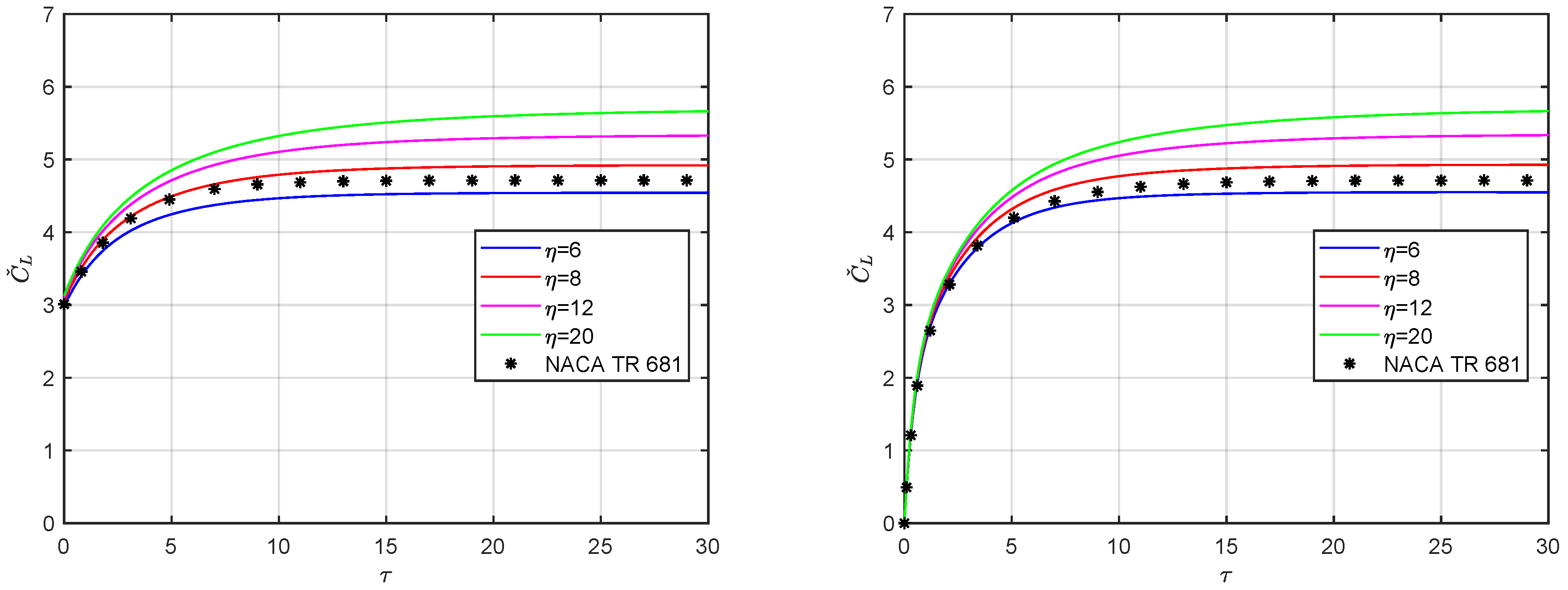
Figure 1. The indicial circulatory lift for elliptical thin wing in incompressible flow: AOA (left) and SEG (right).
Acoustics 04 00003 g001
Figure 2. The indicial airload derivatives (left) and approximate incipient behaviours (right) for thin aerofoil in incompressible flow.
Acoustics 04 00003 g002
Figure 3. The approximate downwash gradient (left) and incipient angle (right) from a unit AOA step for thin elliptical wings in incompressible flow.
Acoustics 04 00003 g003
Figure 4. The incipient indicial lift for elliptical thin wings in incompressible flow: AOA (left) and SEG (right).
Acoustics 04 00003 g004
Figure 5. The gust penetration delay for thin elliptical and trapezoidal wings: taper (left) and sweep (right) effects along the span.
Acoustics 04 00003 g005
Figure 6. The Mach effect on the incipient indicial lift for thin aerofoil in compressible flow: AOA (left) and SEG (right), with Λ = 0 .
Acoustics 04 00003 g006
Figure 7. The sweep effect on the incipient indicial lift for thin aerofoil in compressible flow: AOA (left) and SEG (right), with M = 0.5 .
Acoustics 04 00003 g007
Figure 8. The incipient indicial lift for elliptical wing in compressible flow: AOA (left) and SEG (right), with η = 6 .
Acoustics 04 00003 g008
Figure 9. The incipient indicial lift for elliptical wing in compressible flow: AOA (left) and SEG (right), with η = 8 .
Acoustics 04 00003 g009
Figure 10. The incipient indicial lift for elliptical wing in compressible flow: AOA (left) and SEG (right), with η = 12 .
Acoustics 04 00003 g010
Figure 11. The incipient indicial lift for elliptical wing in compressible flow: AOA (left) and SEG (right), with η = 20 .
Acoustics 04 00003 g011
Figure 12. The incipient indicial lift for rectangular straight wing in compressible flow: AOA (left) and SEG (right), with η = 8 and Λ = 0 .
Acoustics 04 00003 g012
Figure 13. The incipient indicial lift for rectangular swept wing in compressible flow: AOA (left) and SEG (right), with η = 8 and Λ = 30 .
Acoustics 04 00003 g013
Figure 14. The incipient indicial lift for rectangular straight wing in compressible flow: AOA (left) and SEG (right), with η = 20 and Λ = 0 .
Acoustics 04 00003 g014
Figure 15. The incipient indicial lift for rectangular swept wing in compressible flow: AOA (left) and SEG (right), with η = 20 and Λ = 30 .
Acoustics 04 00003 g015
Publisher’s Note: MDPI stays neutral with regard to jurisdictional claims in published maps and institutional affiliations.