
Acoustic Radiation of a Beam Subjected to Transverse Load


Abstract
1. Introduction
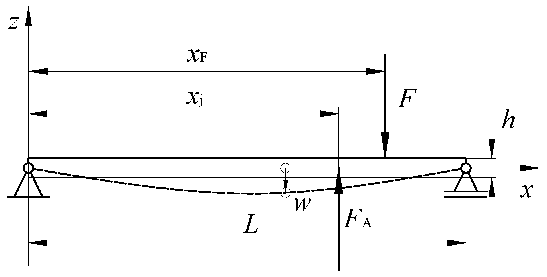
2. Mathematical Model
3. Examples
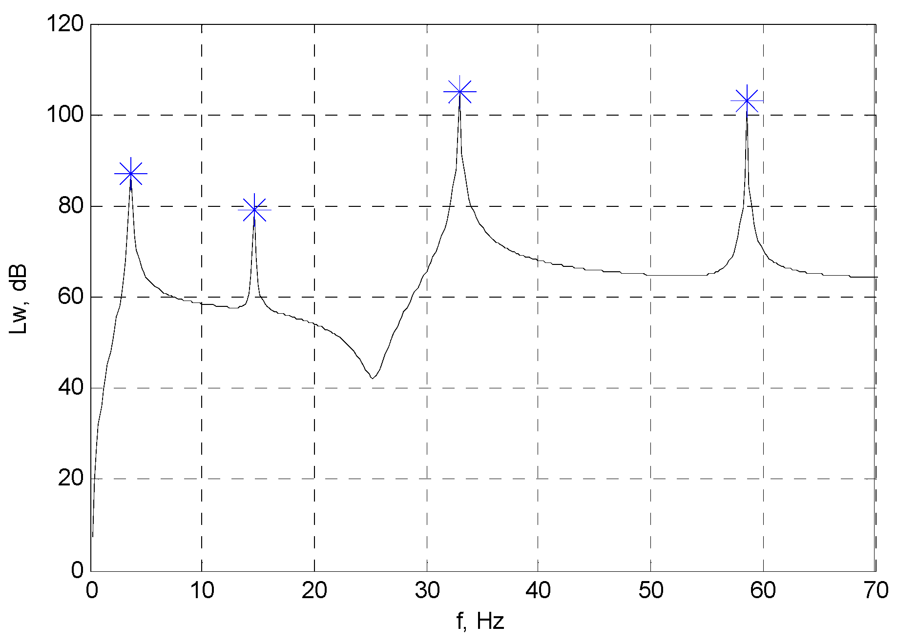
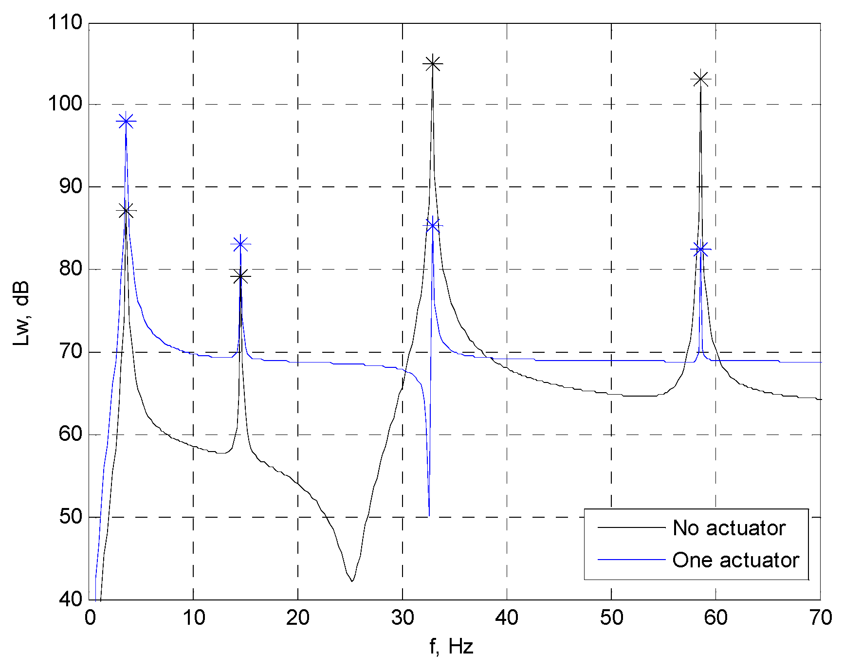
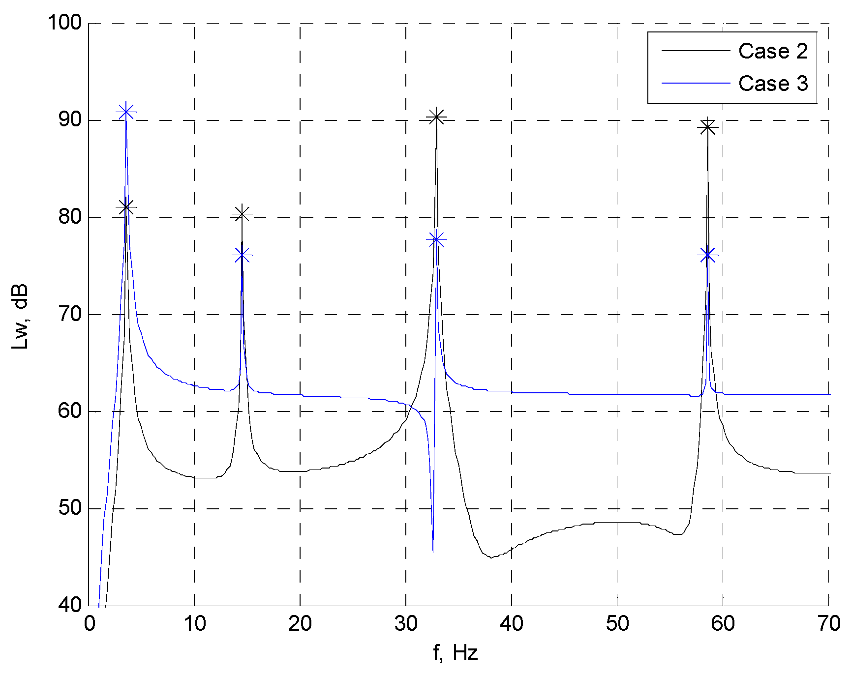
3.1. Comparison of Sound Power Calculations
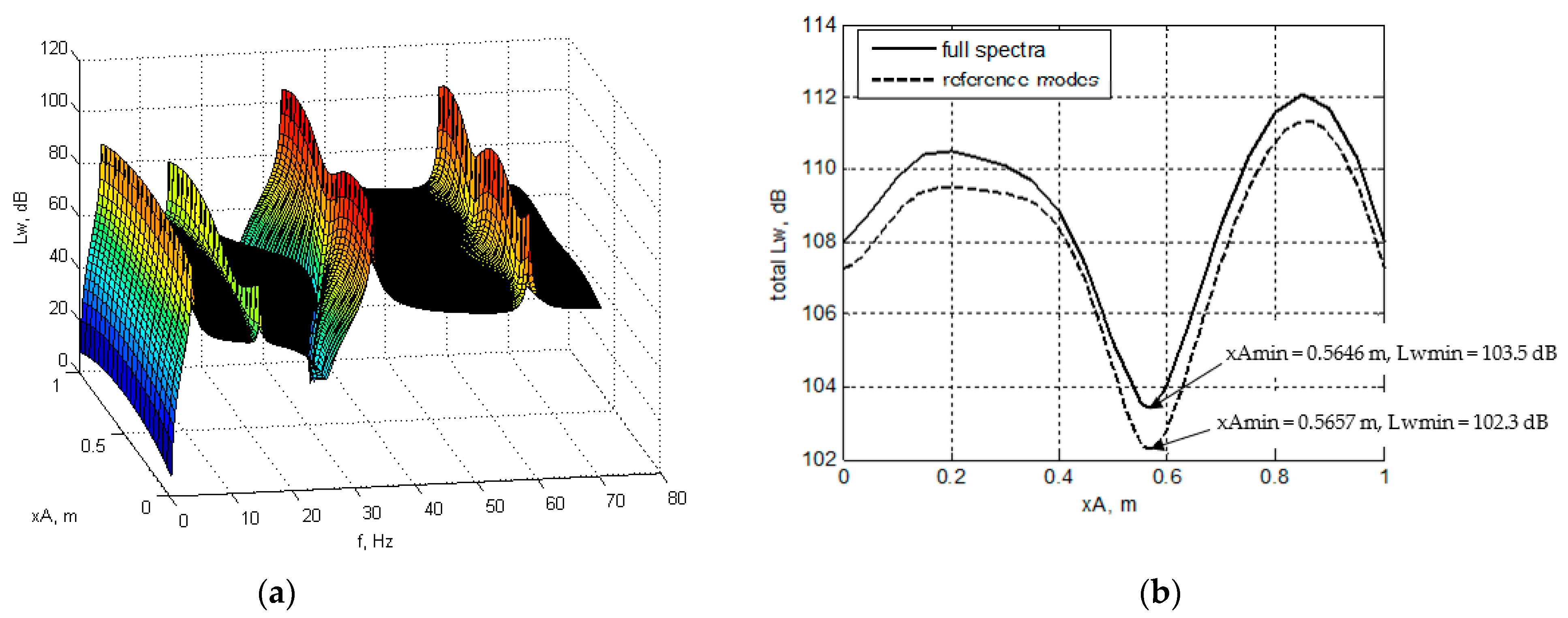
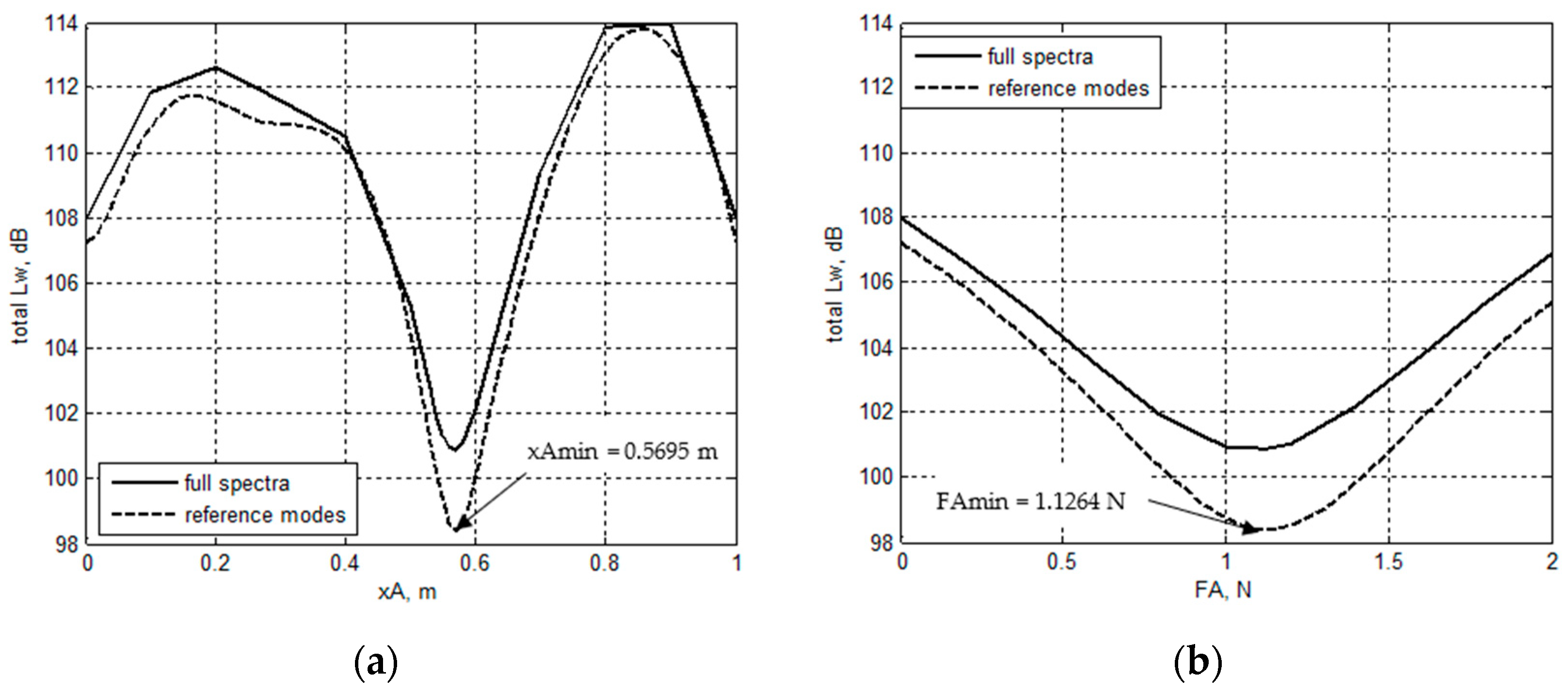
3.2. Position of the Actuator for Minimum Total Sound Power Level
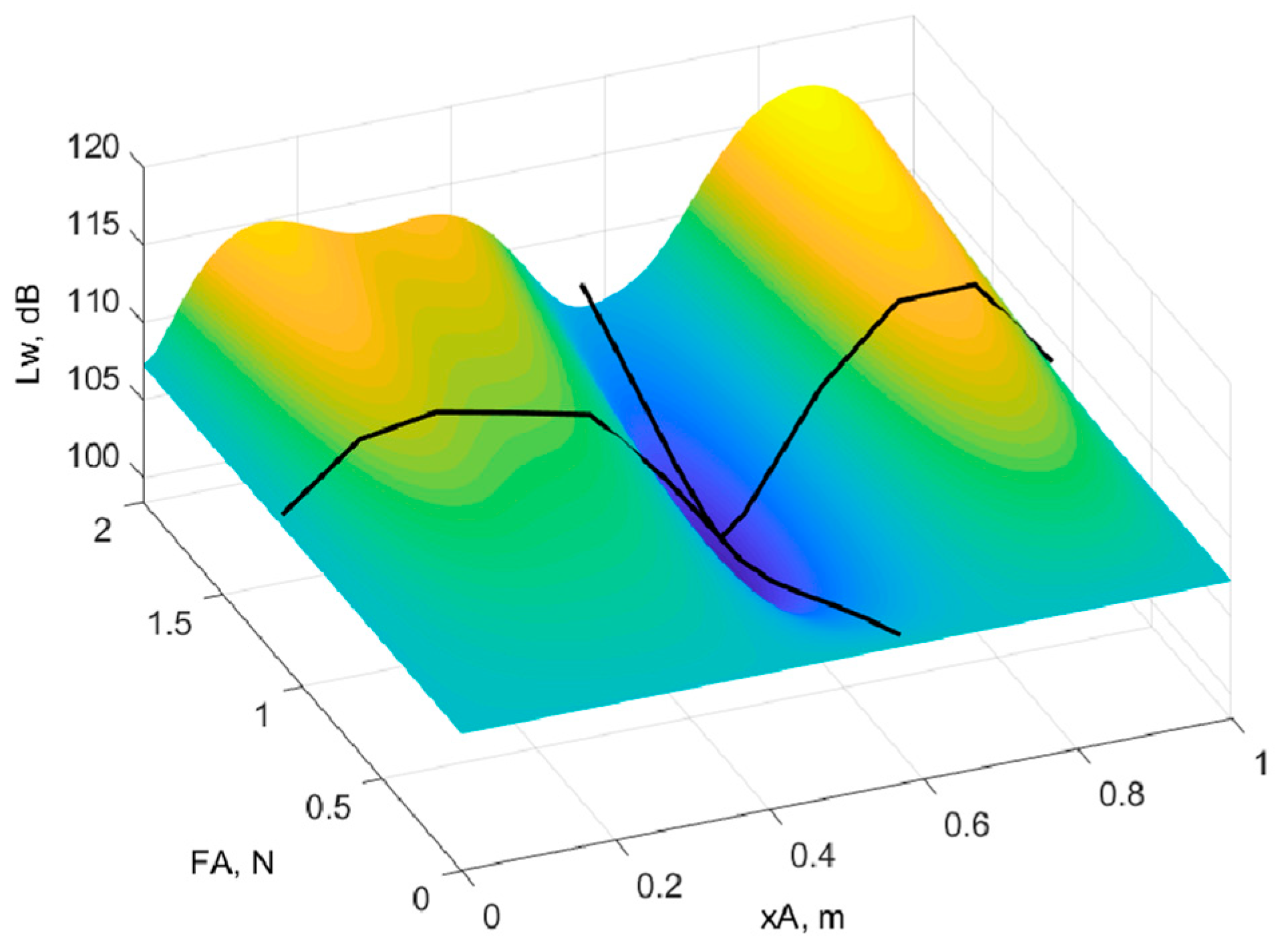
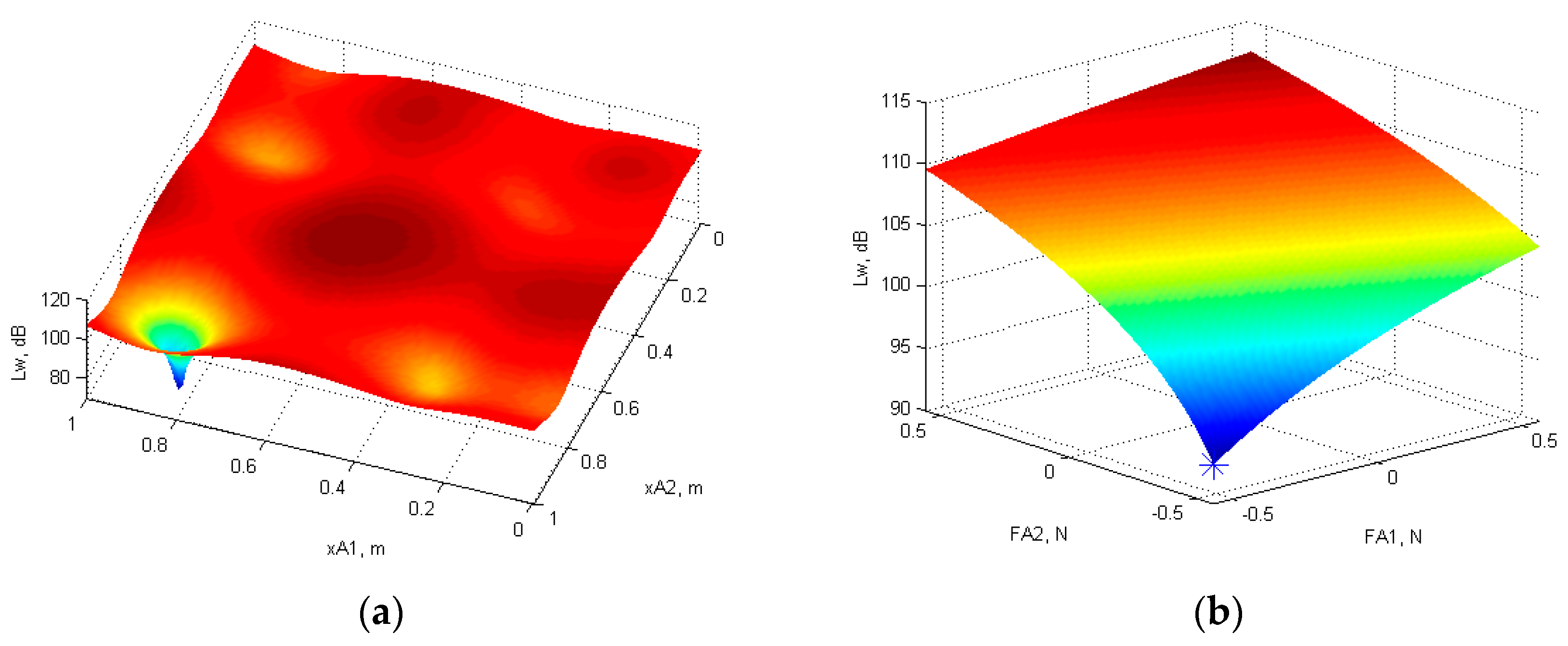
3.3. Optimal Position and Force Amplitude of the Actuator for Minimum Total Sound Power Level
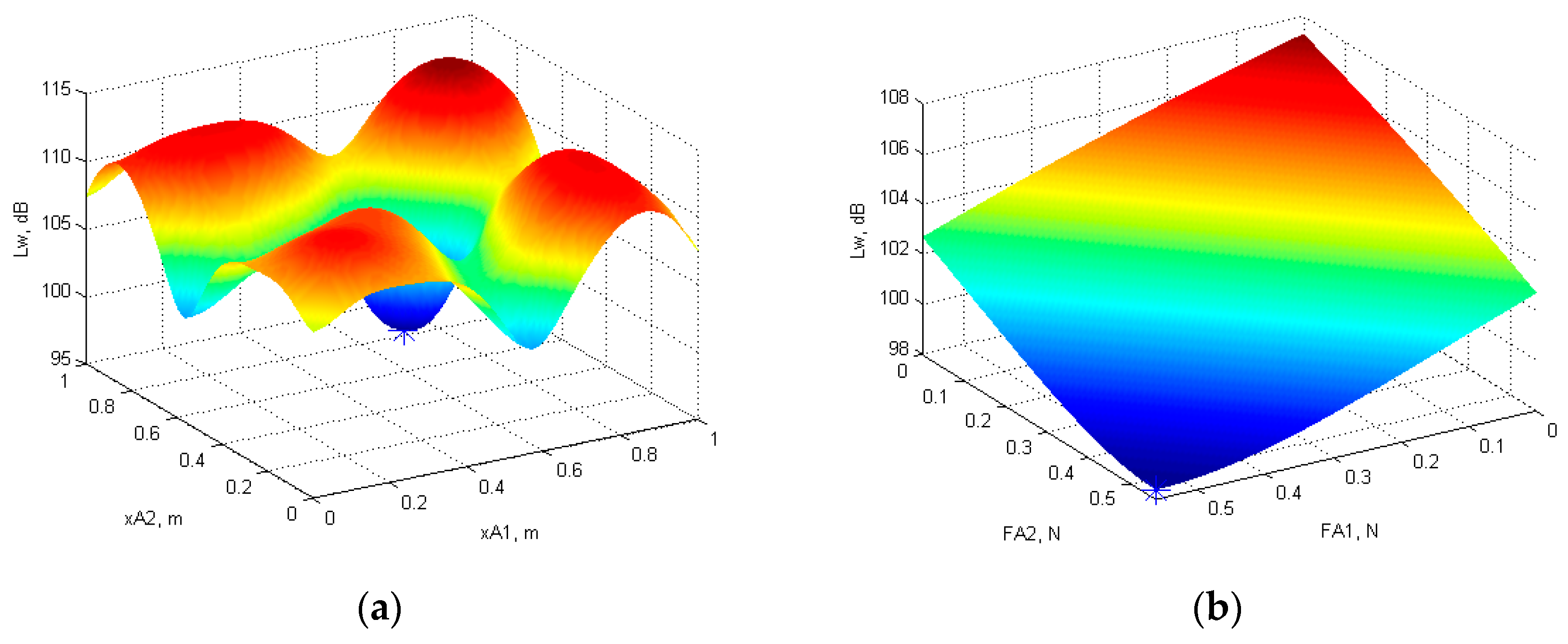
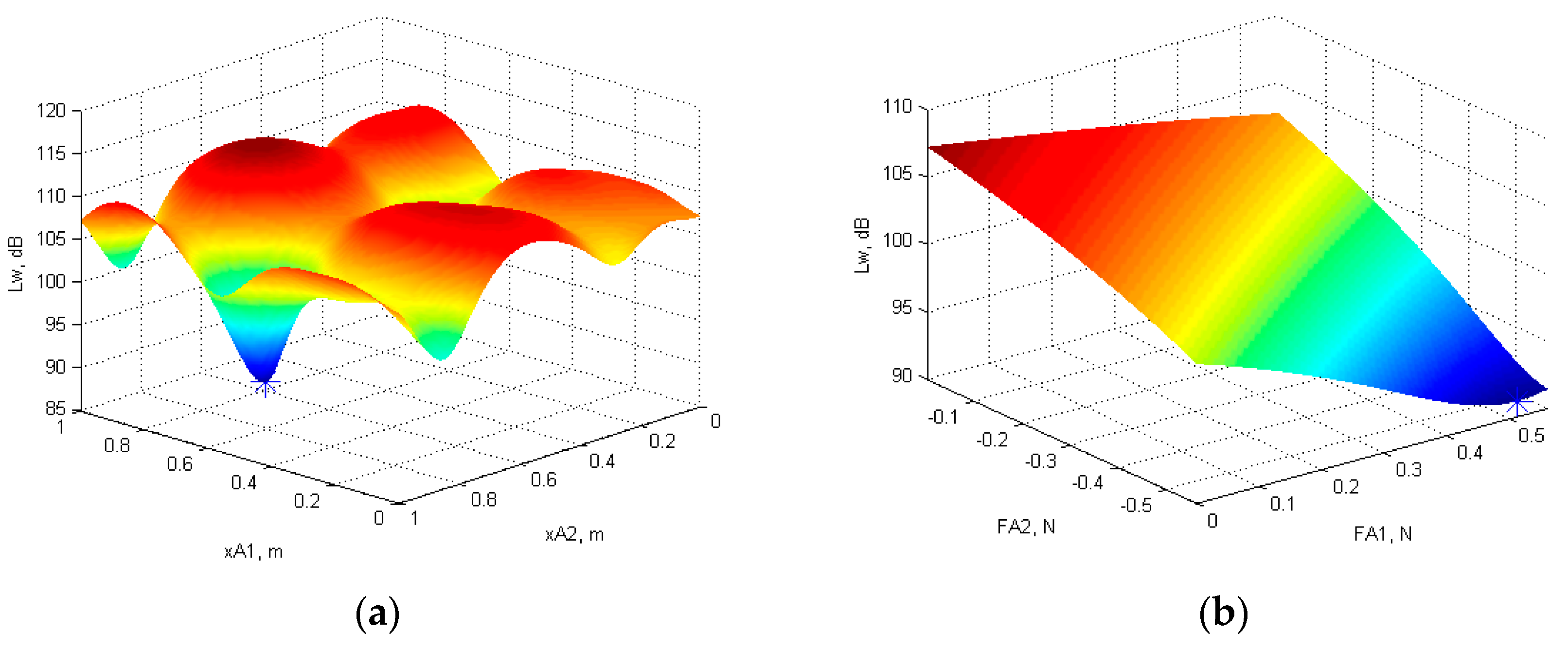
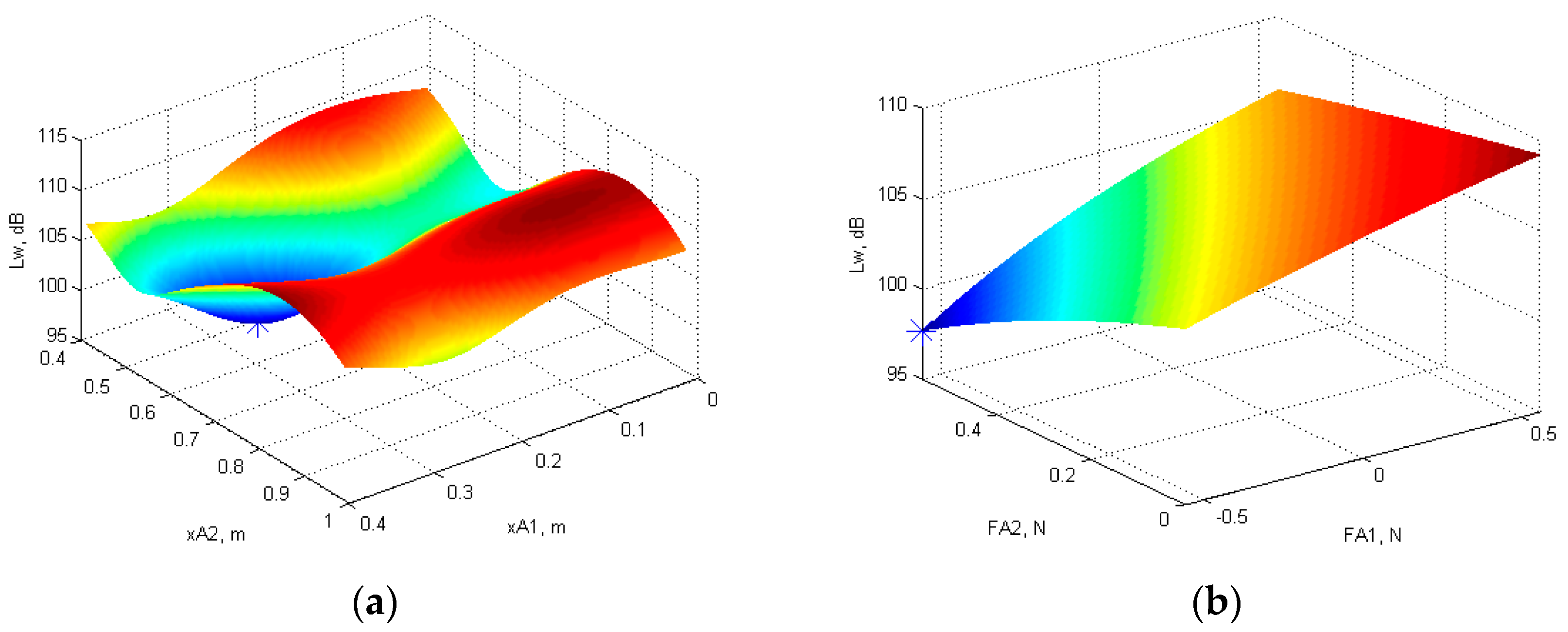
3.4. Optimal Position and Force Amplitude of Two Actuators for Minimum Total Sound Power Level
4. Conclusions
- -
- When one or two actuators are applied in phase with a harmonic load, the optimization results are equal, i.e., two actuators act at the same position as one actuator and the sum of the force amplitudes of two actuators is equal to the force amplitude of one actuator.
- -
- If one actuator acts in antiphase with the harmonic load, its optimal position is always at the position of the harmonic load.
- -
- If two given actuators and the load cannot act in antiphase, the optimal positions of the actuators enable the actuator force to be in antiphase with the velocity of the excited mode shape.
- -
- The most influential input parameter for the optimization of the actuator position is the position of the harmonic load.
Author Contributions
Funding
Data Availability Statement
Conflicts of Interest
References
- Dimino, I.; Aliabadi, F. Active Control of Aircraft Cabin Noise; Imperial College Press: London, UK, 2015. [Google Scholar]
- Preumont, A. Vibration Control of Active Structures, 2nd ed.; Kluwer Academic Publishers: Dordrecht, The Netherlands, 2003. [Google Scholar]
- Fahy, F.; Gardonio, P. Sound and Structural Vibration: Radiation, Transmission and Response, 2nd ed.; Academic Press: London, UK, 2007. [Google Scholar]
- Nayan, A.; Kam, T.Y. Sound enhancement of orthotropic sound radiation plates using line loads and considering resonance characteristics. Acoustics 2021, 3, 642–664. [Google Scholar] [CrossRef]
- Wei, L.; Sheng, L. Mutual-radiation efficiency estimation of vibration modes by finite element method and boundary element method software. J. Low Freq. Noise Vib. Act. Control 2022, 41, 1131–1142. [Google Scholar] [CrossRef]
- Keltie, R.F.; Peng, H. The effects of modal coupling on the acoustic power radiation from panels. J. Vib. Acoust. Stress Reliab. Des. 1987, 109, 48–54. [Google Scholar] [CrossRef]
- Snyder, S.D.; Tanaka, N. Calculating total acoustic power output using modal radiation efficiencies. J. Acoust. Soc. Am. 1995, 97, 1702–1709. [Google Scholar] [CrossRef]
- Li, W.L.; Gibeling, H.J. Determination of the mutual radiation resistances of a rectangular plate and their impact of the radiated sound power. J. Sound Vib. 2000, 229, 1213–1233. [Google Scholar] [CrossRef]
- Ringwelski, S.; Luft, T.; Gabbert, U. Piezoelectric controlled noise attenuation of engineering systems. J. Theor. Appl. Mech. 2011, 49, 859–878. [Google Scholar]
- Lan, L.; Cheng, S.; Sun, X.; Li, W.; Yang, C.; Wang, F. A fast singular boundary method for the acoustic design sensitivity analysis of arbitrary two-and three-dimensional structures. Mathematics 2022, 10, 3817. [Google Scholar] [CrossRef]
- Cheng, S.; Wang, F.; Wu, G.; Zhang, C. A semi-analytical and boundary-type meshless method with adjoint variable formulation for acoustic design sensitivity analysis. Appl. Math. Lett. 2022, 131, 108068. [Google Scholar] [CrossRef]
- Makarenko, V. Modeling and control of sound radiation by simply supported and cantilever beam coupled with smart material. Vìsnik NAU 2007, 3, 142–150. [Google Scholar] [CrossRef]
- Anderson, D.A.; Heilemann, M.C.; Bocko, M.F. Optimized driver placement for array-driven flat-panel loudspeakers. Arch. Account. 2017, 42, 93–104. [Google Scholar] [CrossRef]
- Kournoutos, N.; Cheer, J. A system for controlling the directivity of sound radiated from a structure. J. Acoust. Soc. Am. 2019, 147, 231–241. [Google Scholar] [CrossRef] [PubMed]
- Wrona, S.; Pawelczyk, M.; Cheer, J. Acoustic radiation-based optimization of the placement of actuators for active control of noise transmitted through plates. Mech. Syst. Signal. Process. 2021, 147, 107009. [Google Scholar] [CrossRef]
- Rao, S.S. Vibration of Continuous Systems; John Wiley & Sons, Inc.: Hoboken, NJ, USA, 2007. [Google Scholar]
- Rončević, G.Š.; Rončević, B.; Skoblar, A.; Žigulić, R. Closed form solutions for frequency equation and mode shapes of elastically supported Euler-Bernoulli beams. J. Sound Vib. 2019, 457, 118–138. [Google Scholar] [CrossRef]
- Skoblar, A.; Žigulić, R.; Braut, S. Numerical ill-conditioning in evaluation of the dynamic response of structures with mode superposition method. Proc. Inst. Mech. Eng. C J. Mech. Eng. Sci. 2017, 231, 109–119. [Google Scholar] [CrossRef]
- Zaporozhets, A.; Tokarev, V.; Hufenbach, W.; Taeger, O.; Modler, N.; Dannemann, M.; Makarenko, V. Parametric investigation of acoustic radiation by a beam under load and actuator forces. Vìsnik NAU 2005, 26, 122–133. [Google Scholar] [CrossRef]
- Wallace, C.A. Radiation resistance of a baffled beam. J. Acoust. Soc. Am. 1972, 51 Pt 2, 936–945. [Google Scholar] [CrossRef]
- Schittkowski, K.; Yuan, Y.X. Sequential Quadratic Programming Methods. In Wiley Encyclopedia of Operations Research and Management Science; John Wiley & Sons, Inc.: Hoboken, NJ, USA, 2011. [Google Scholar] [CrossRef]


| 1. Mode Shape | 2. Mode Shape | 3. Mode Shape | 4. Mode Shape | |
|---|---|---|---|---|
| Total response | 29.5426 | 5.2018 | 155.3559 | 94.9151 |
| Ref. m. shape | 29.6208 | 5.1174 | 155.2531 | 94.2995 |
| Case 1 | Case 2 | Case 3 | Case 4 | ||
|---|---|---|---|---|---|
| 0.5632 | −0.5632 | −0.3264 | 0.5109 | −0.5632 | |
| 0.5695 | 0.2812 | 0.2784 | 0.5748 | 0.2834 | |
| 0.5632 | −0.5632 | −0.8000 | −0.5632 | 0.5632 | |
| 0.5695 | 0.8579 | 0.8592 | 0.8369 | 0.5690 | |
| 98.379 | 93.1982 | 83.5471 | 91.1552 | 97.6596 | |
| Case 1 | Case 2 | Case 3 | |
|---|---|---|---|
| 0.3 | −0.3 | 0.3 | |
| 0.568 | 0.2787 | 0.5672 | |
| 0.3 | −0.3 | −0.3 | |
| 0.568 | 0.856 | 0.8542 | |
| 102.2909 | 102.2606 | 100.801 |
Disclaimer/Publisher’s Note: The statements, opinions and data contained in all publications are solely those of the individual author(s) and contributor(s) and not of MDPI and/or the editor(s). MDPI and/or the editor(s) disclaim responsibility for any injury to people or property resulting from any ideas, methods, instructions or products referred to in the content. |
© 2023 by the authors. Licensee MDPI, Basel, Switzerland. This article is an open access article distributed under the terms and conditions of the Creative Commons Attribution (CC BY) license (https://creativecommons.org/licenses/by/4.0/).
Share and Cite
Skoblar, A.; Štimac Rončević, G.; Lanc, D.; Braut, S. Acoustic Radiation of a Beam Subjected to Transverse Load. Acoustics 2023, 5, 462-475. https://doi.org/10.3390/acoustics5020027
Skoblar A, Štimac Rončević G, Lanc D, Braut S. Acoustic Radiation of a Beam Subjected to Transverse Load. Acoustics. 2023; 5(2):462-475. https://doi.org/10.3390/acoustics5020027
Chicago/Turabian StyleSkoblar, Ante, Goranka Štimac Rončević, Domagoj Lanc, and Sanjin Braut. 2023. "Acoustic Radiation of a Beam Subjected to Transverse Load" Acoustics 5, no. 2: 462-475. https://doi.org/10.3390/acoustics5020027
APA StyleSkoblar, A., Štimac Rončević, G., Lanc, D., & Braut, S. (2023). Acoustic Radiation of a Beam Subjected to Transverse Load. Acoustics, 5(2), 462-475. https://doi.org/10.3390/acoustics5020027