Article

Influence of Embedded Charging Units Characteristics on Long-Term Structural Behavior of E-Roads

Department of Civil and Environmental Engineering, Politecnico di Milano, Piazza Leonardo da Vinci 32, 20133 Milan, Italy
*
Author to whom correspondence should be addressed.
Smart Cities 2022, 5(3), 756-770; https://doi.org/10.3390/smartcities5030039
Submission received: 27 May 2022 / Revised: 20 June 2022 / Accepted: 22 June 2022 / Published: 23 June 2022
(This article belongs to the Section Smart Urban Infrastructures)

Abstract

:
The use of Electric Vehicles (EV) seems to be a promising solution to achieve a sustainable road transport system. Among the contactless dynamic vehicle charging technologies, the use of Charging Units (CUs)—cement concrete box—embedded into the road pavement seems to be a favorable option. The available scientific papers related to the structural effects of embedding CUs in road pavements consider the CU as a solid box, even if a cavity is needed for the electrical technologies’ accommodation. This is why the current research is aimed at studying electrified roads (e-road) with different CU cavity shapes and dimensions. In detail, pavement structural responses are investigated, as a first step, adopting a Finite Element Model (FEM), and, as a second step, the long-term performances (fatigue cracking/rutting proneness) are evaluated. The study is divided into two phases: the theoretical fatigue/rutting assessment, which allows to calculate the critical load repetitions leading to pavement failure, and an urban case study with the goals of both assessing the theoretical results and computing fatigue/rutting performance with real scale traffic conditions. The outcomes demonstrate that CUs can be used with no significant impacts on the long-term road pavement structural performance, laying the foundation for a future upgrading of the existing urban road networks.

1. Introduction

To achieve a sustainable road transport system, the use of Electric Vehicles (EV) seems to be a promising solution. However, according to [1], the distribution of alternative fuel (BEV Battery Electric Vehicle, PHEV Plug-in Hybrid Electric Vehicle, H2 Hydrogen vehicle, LPG Liquified Petroleum Gas, CNG Compressed Natural Gas, LNG Liquified Natural Gas) fleets is lower than 15% of the total, as reported in Figure 1 and Figure 2, for EU-27 during 2021. The main problems related to EV worldwide diffusion are: high initial cost, long charging time, and range anxiety [2,3]. All these obstacles are mainly due to the battery on board. In fact, there is a direct correlation between battery dimension (therefore, cost) and travel distance (related to range anxiety). In case of considering the goal as EV cost reduction, the battery dimension has to be decreased with a consequent increase in range anxiety [4]. Based on this, the on-the-road charging appears as an encouraging solution to overcome the above limitations. In this case, the battery can be smaller without negatively affecting the travel distance. Moreover, a smaller battery decreases the total EV weight, with advantages in terms of energy consumption and pavement damage [5]. A road equipped with a proper electric charging network is called electrified road (e-road). From the available literature, two charging methods are investigated [2,3]: the conductive method (a connection that links the EV with the charging network) and the contactless one (a defined air gap divides EV and the charging network, using for example an inductive coupled power transfer to charge the EV battery). Among the contactless dynamic vehicle charging technologies, the use of Charging Units (CUs)—cement concrete box—embedded into the road pavement seems to be a promising solution, even if the CUs’ effects on the structural road pavement performance are not yet fully investigated. In fact, the available scientific papers consider the CU as a solid box [2,6,7,8,9], even if, from the electrical point of view, a cavity into the CU is needed for the electrical technologies’ accommodation. This is the reason why the research described in this paper is devoted to investigating different CU cavity shapes and dimensions, also considering the long-term effects, particularly related to both fatigue and rutting proneness. Therefore, the current research is divided in three parts:
  • Optimization of void CU material, shape, and dimension, considering a 2D Finite Element approach and typical material characteristics from scientific literature;
  • Fatigue resistance of e-road_void CU, considering some of the optimized void CU geometries. This part is separated into two steps: the theoretical fatigue assessment, which allows to calculate the critical load repetitions leading to pavement failure, and the case study of Viale Forlanini in Milan, which allows to determine the pavement DI under specific traffic conditions;
  • Rutting resistance of e-road_void CU, considering some of the optimized void CU geometries. In line with the previous one, also this part is divided in two steps: the theoretical rutting assessment, which allows to calculate the critical load cycles leading to rut an e-road pavement for a particular Rut Depth (RD) and the case study of Viale Forlanini in Milan, which allows to determine the pavement RD under specific traffic conditions.
Considering the CU long-term effects on pavement performances, according to Miner’s law, fatigue cracking simulation is based on the cumulative damage theory, in which the Damage Index (DI) is calculated using Equation (1). From a theoretical point of view, fatigue cracking arises at DI equal to 1 [10]. Among the different models useful to calculate the allowable number of axle loads Nf, the bottom-up one is considered. In this case, the fatigue cracking starts at the bottom of the asphalt layer and propagates upwards to the surface [11]. Thus, traffic repetitions Nf—that lead to a bottom-up fatigue cracking—are calculated using Equations (2) to (5), proposed by AASHTO [11].
D I = i = 1 T ( n i / N f i )
where: DI = Damage Index; T = total number of periods; ni = actual number of load repetitions in period i; Nfi = allowable number of axle loads (that leads to failure) in period i.
N f = 0.007566 · C · C H · ε t 3.9492 · E 1.281
C = 10 M
M = 4.84 · { [ V b / ( V a + V b ) ] 0.69 }
C H = ( 0.000398 + 0.003602 1 + e 11.02 3.49 · H H M A ) 1
where: C = laboratory to field adjustment factor; Vb = effective binder content by volume (%); Va = air voids in the Hot Mix Asphalt (HMA) mixture (%); CH = thickness correction term; HHMA = total HMA thickness in [in]; εt = horizontal tensile strain at the critical location [–]; E = stiffness of HMA measured in [psi].
As concerns rutting, the evaluation of rutting resistance involves the calculation of the rut depth at the end of the distress-related pavement service life. Rut depth is a surface depression along the wheel path derived by permanent deformations in each pavement layer, as a consequence of load cycles. From scientific and technical literature, the maximum rut depth stands in the interval between 6 and 15 mm [12,13,14].
Among the several equations available in the scientific literature, Equation (6) enables the calculation of permanent deformation in unbound material, as shown in [15]. Taking into consideration that permanent strains are proportional to elastic strains, the former equation is harmonized to HMA [16]. Thus, Equation (7) is used for bituminous layers. Concerning the subgrade layer, Heukelom and Klomp formula allows us to compute permanent deformation based on the maximum acceptable vertical stress, as shown in Equation (8).
ε p , u n b o u n d   m a t e r i a l = 2 · ε y y · n b
ε p , H M A = 4.49 · ε y y · n 0.25
ε p , s u b g r a d e = ε y y · ( 1 + 0.7 · log n )
where: εyy is the vertical compressive strain; n is the actual number of load repetitions; b is a coefficient equal to 0.2 (thickness higher than 0.12 m) or 0.3 (thickness lower than or equal to 0.12 m).

2. Materials and Methods

2.1. Optimization of Void CU Material, Shape and Dimension

Four e-roads cross-sectional geometries are examined, as shown in Figure 3. All e-roads are marked by identical CU external dimensions, with a height of 0.14 m (equal to the binder course thickness) and a width of 0.80 m. Each pavement is characterized by a specific void CU geometry for the electrical devices positioning, as follows:
  • Void CU_R1: this is the simplest geometry, showing a rectangular cavity (R1), as studied in previous Author’s research [2];
  • Void CU_R2: this geometry has a vertical cavity partition that leads to two rectangular cavities (R2);
  • Void CU_C4: this geometry is characterized by four circular cavities (C4) equally distributed along CU horizontal axis;
  • Void CU_C6: this geometry is characterized by six circular cavities (C6) equally distributed along CU horizontal axis.
As concerns materials, the main properties of asphalt concrete, cement treated subbase and subgrade are given in [2]. Regarding concrete, three compressive strength classes are considered: C20/25, C30/37, and C40/50, according to [17]. The main characteristics of each class are reported in Table 1, in which failure tensile stress fctm is calculated using Equation (9) from [18].
f c t m = 0.30 · f c k 2 / 3
where: fck is the characteristic compressive strength of concrete determined by testing cylinders.
Since road vehicles do not have physical constrains during travel, three load positions are considered: centered on CU, in which the EV is in the middle of the lane; CU edge, in which the EV left wheel stands on CU left edge; CU center, in which the EV left wheel is positioned along CU center.
As aforementioned, a 2D FEM is implemented using COMSOL Multiphysics 6.0 software to obtain stresses and strains on the entire pavement domain. More details about load characteristics, model boundary conditions, and mesh construction are given in [2].
Based on this, several combinations are tested, varying both CU geometries and concrete characteristics, in order to obtain the wider cavity area—for the electrical device accommodation—that is consistent with the operating loads. The obtained results are shown in Table 2, in which the thickness of CU (up, down, and lateral) and the cavity dimension/area are presented for each CU geometry and concrete Young’s modulus. The ID code refers to the CU geometry (R1/R2 stand for the rectangular cavities and C4/C6 for the circular ones) and the Young’s modulus (25/33/35 stand for 25,000/33,000/35,000 N/mm2). E-road_void CU_R1_25, studied in previous research [2], is assumed to be the reference cross-sectional geometry. As a first general comment, it is possible to note that an increase in Young’s modulus leads to an increase in cavity area, for the same CU geometry. More in detail, considering rectangular cavities, the cavity area increases by 33% (R1_33), 67% (R1_35), 488% (R2_25), 522% (R2_33), and 555% (R2_35) compared to R1_25. As highlighted, R2_35 is the geometry characterized by the wider cavity area with benefit for electrical device positioning. As regards circular cavities, the CU thickness with Young’s modulus of 33,000 N/mm2 is equal to the thickness with a modulus of 35,000 N/mm2. This is the result of a design technological choice regarding CU construction, which considers a minimum of 0.02 m for up/down CU thickness. Therefore, the cavity area increases by 179% (C4_25), 319% (C6_25), 336% (C4_33 and C4_35), and 554% (C6_33 and C6_35) with respect to R1_25. Based on these results, it is possible to note that R2_35 has the same cavity area as C6_33/C6_35.
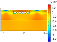
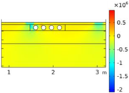
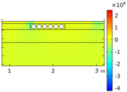
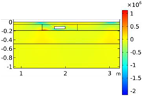
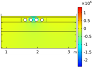
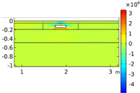
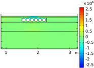
By way of example, Table 3 shows the vertical/horizontal stresses distribution for some of the optimized geometries according to load positions. By analyzing these graphs, it is possible to note that the stress distributions are affected by load positions. In fact, when a vehicle is centered on CU, stresses effects on CU are low, especially along vertical direction. On the contrary, when the load is on CU edge, an increase in stresses is evident both on CU and inside wearing/binder course. Considering the last load position, a stress concentration arises near CU cavity, with slight effects on wearing course.

2.2. Methodology

2.2.1. Fatigue

The experimental plan of fatigue assessment is shown in Figure 4, tracing the approach adopted in [19].
Among the different optimized geometries shown in the previous section, four e-road cross-sectional geometries are analyzed in terms of fatigue resistance: R1_35, R2_35, C4_33, and C6_33.
Regarding materials, concrete has the characteristics reported in Table 1; cement treated subbase and subgrade properties are discussed in [2]. Asphalt concrete key characteristics are summarized in Table 4, by separating the theoretical approach and the case study. As concerns the latter, bituminous mixtures were previously investigated by the Authors [19,20,21]. Since the characteristics of asphalt concrete are affected by temperature, the behavior at low/high temperatures (seasons) are evaluated using two different approaches [19]: an increase/decrease by 50% of the Young’s modulus at 20 °C (theoretical assessment) and Master Curves moduli at specific pavement temperatures (case study). As aforementioned, three load positions are examined.
Based on this, 36 FEM simulations are performed to calculate stresses and strains in the entire pavement domain. In particular, the maximum horizontal tensile strain at the interface (binder-cement treated subbase) for each simulation is of interest for fatigue resistance analysis. The interface analysis choice is given by previous results obtained by the Authors [19]. The allowable number of axle loads are calculated using the bottom-up model—Equations (2) to (5)—that is considered as more representative of the pavement fatigue life [19]. The data used in that model are shown in Table 5, both for the theoretical approach and the case study.
The theoretical assessment and the case study share the process described above. The availability of traffic data leads to two different approaches, as detailed in the following:
  • Theoretical assessment: since the actual traffic is unknown, Miner’s law cannot be applied in a traditional manner. Considering that, theoretically, fatigue cracking appears at DI equal to 1, it is possible to calculate the number of traffic repetitions that leads to that damage value.
  • Case study: the actual traffic in Viale Forlanini (Milan) is available, therefore, Miner’s law can be used to calculate pavement DI. Two traffic conditions are examined, as explained in [19]: traffic on one lane—conservative assumption—(5.75 × 10⁷ ESAL) and traffic equally distributed on two lanes (2.88 × 10⁷ ESAL).

2.2.2. Rutting

The experimental plan of rutting assessment is shown in Figure 5.
In line with the previous section:
  • Four e-road cross-sectional geometries are analyzed: R1_35, R2_35, C4_33, and C6_33;
  • The characteristics of each material are listed below:
    • Asphalt concrete characteristics are summarized in Table 4, by separating the theoretical approach and the case study;
    • Cement treated subbase and subgrade properties are shown in [2];
    • Concrete characteristics are reported in Table 1.
  • Three load positions are examined: centered on CU, CU edge, and CU center.
Based on this, 36 FEM simulations are performed to calculate stresses and strains in the pavement domain. In particular, maximum compressive strains are required to calculate the permanent strains in each layer, as shown in Equation (6) to Equation (8). The maximum vertical compressive strains are evaluated along defined analysis sections: at the interface between layers and inside the subgrade layer (y = −0.59 m). This approach is in line with the one adopted to assess fatigue resistance. To summarize, 144 analyses (4 cross-sectional geometries, 3 load positions, 3 temperatures, 4 analysis sections) are carried out in order to calculate the maximum vertical compressive strains in each layer. It is important to note that a granular material model—Equation (6) with b-coefficient equal to 0.2—is adopted for the calculation of cement treated subbase permanent strains. In fact, in these FEM simulations, the subbase is studied as a cracked material.
As described in the previous section for fatigue resistance, the theoretical assessment and the case study share the process detailed above; instead, the availability of traffic data leads to two different approaches, as follows:
  • Theoretical assessment: since the actual traffic is unknown, RD cannot be calculated. Therefore, the aim of this part is the identification of traffic repetition numbers that lead to rut a pavement for a defined depth equal to 1.5 cm [12,13,14]. A spreadsheet solver is developed to calculate those critical cycle numbers.
  • Case study: the actual traffic in Viale Forlanini (Milan) is available, therefore, it is possible to calculate the RD. As shown in [19], two traffic conditions are studied: total traffic vehicles on one or two lanes.

3. Results and Discussion

3.1. Theoretical Assessment Results

Since the CUs’ effects on long-term performances of pavements are not yet investigated, as demonstrated by the available scientific literature [6,7], the research herein described is aimed at studying both fatigue and rutting proneness of these new e-roads.
Regarding fatigue, the Miner’s approach is used. The results obtained by applying the aforementioned Miner’s law are shown in Table 6, in which the numbers of axle loads—that lead to DI equal to one—are presented according to cross-sectional geometries and load positions.
The most critical load position is along CU edge. These results decrease by 20.36% (R1_35), 8.11% (R2_35), 88.72% (C4_33), and 96.15% (C6_33) compared to the ones obtained considering the same cross-sectional geometries and load centered on CU. The outcomes achieved when the load is on CU center are similar to those obtained considering load centered on CU. In particular, concerning rectangular cavities, it is possible to note increases of 14.36% (R1_35) and 6.05% (R2_35) in CU center compared to centered on CU. Instead, CUs with circular cavities have an opposite behavior, in which the CU center results decrease by 4.94% (C4_33) and 5.60% (C6_33) with respect to the centered on CU.
From the comparison between R2_35 and F6_33 (characterized by the same cavity area), it is possible to note load repetitions increases by 1.95% (centered on CU), 2336.71% (CU edge), and 14.95% (CU center) in the case of rectangular cavities with respect to the circular voids.
Table 7 shows the lowest numbers of traffic repetitions that lead to the pavement failure, for each cross-sectional geometry. In addition to the void CU geometries discussed in the present paper, some of the CU analyzed in the Author’s previous paper [19] are considered: e-road_solid CU_25 (no cavity for the electrical device accommodation) and e-road_ void CU_R1_25 (one rectangular cavity in CU, characterized by a Young’s modulus of 25,000 N/mm2). By comparing the geometry having a rectangular cavity, it is possible to note an increase of traffic repetition by 37.39% in R1_35 with respect to R1_25. Moreover, considering the same Young’s modulus (35,000 N/mm2) and a cavity area increase of four times, the R2_35 critical load cycles are higher (26.23%) than the ones in R1_35. Finally, by comparing the smallest and the widest cavity area, an increase in R2_35 by 56.50% is evident with respect to the solid CU_25.
Considering the rutting phenomena, the traffic repetitions (that lead to rut a pavement for a depth of 1.5 cm) are reported in Table 8, according to cross-sectional geometries and load positions.
Once again, the rutting results are affected by load positions. When load is centered on CU, the maximum critical load cycles number (R2_35) increases by 7% with respect to the lowest one (R1_35). Considering the load on CU edge, the differences between results are more visible, an increase in R1_35 by 268% compared to F6_33 is appreciable. Contrary to the fatigue results, traffic repetitions differences can be seen also when the load is along CU center. Increases of 259% (R1_35), 254% (F4_33), and 206% (F6_33) are recorded with respect to the lowest R2_35 value. This last geometry is more affected by load positions compared to the other CU geometries. In fact, for R2_35, increases of 268% (centered on CU) and 67% (CU edge) are obtained with respect to the load along CU center.
From the comparison between R2_35 and F6_33 (characterized by the same cavity area), it is possible to note that R2_35 load repetitions increase by 2% (centered on CU) and 103% (CU edge) and decrease by 67% (CU center) compared to the CU having circular cavities. The lowest number of traffic repetitions belongs to F6_33 and load along CU edge.
The comparison between the critical load cycles for both fatigue and rutting phenomena is shown in Figure 6, according to CU geometries and load positions.
Ideally, by dividing the graph into four quadrants, it is possible to note that most of the dots (combinations of CU geometries and load positions) are positioned in the upper right quadrant. Therefore, these configurations simultaneously show high performance in terms of both fatigue and rutting resistances.
Red dots (R2_35) are in the upper part of the graph, showing high fatigue performance. However, red dots corresponding to the load on CU edge/CU center are in the left quadrant, revealing poor rutting resistance.
Only two dots (equivalent to CU with circular cavities and load on CU edge) are located in the lower left quadrant. Thus, these combinations are characterized by low performances in both fatigue and rutting life.
The worst case (the lowest numbers of fatigue and rutting repetitions) for both phenomena is represented by C6_33 and load along CU edge.

3.2. Case Study Results

Table 9 shows the results of the Damage Index, calculated using Equation (1), for the different e-roads according to load positions and traffic conditions. In both traffic situations, the same trend of DI values can be noted.
By comparing the two traffic hypotheses, the conservative assumption results are about double of those obtained when vehicles travel on two lanes. Therefore, an increase in traffic repetitions leads to an increase in pavement damage, as can be guessed.
The most critical load position is CU edge, in line with the theoretical approach results. In particular, CU edge DI values increase from 13% (R2_35) to 800% (C6_33) and from 21% (R2_35) to 721% (C6_33) compared to load centered on CU and load on CU center, respectively. Considering the latter two load positions, results are similar: the highest DI difference is equal to 15% (R1_35) with respect to load centered on CU.
When load is centered on CU or along CU center, the cross-sectional geometries results are comparable, whose maximum value is slightly higher (about 17%) than the minimum one. Instead, when the load is along CU edge, C6_33 is characterized by the highest DI value, which increases by 698% compared to the lowest one (R2_35). In general, the geometries having circular cavities are more affected by load positions compared to the CU with rectangular cavities.
Except for C6_33, which is characterized by DI result beyond the limit (179% and 39% considering traffic on one and two lanes, respectively), DI values of the different CU geometries are lower than 1, even in the case of conservative assumption. These low results are in line with the outcomes gained in [19]. Therefore, F6_33 is not consistent with Viale Forlanini’s traffic.
Table 10 shows the results of RD, for the different e-road cross-sectional geometries according to load positions and traffic conditions. In both hypotheses, the same trend of RD values can be noted. The two-lanes results are lower (decrease of 15%) than those considering traffic on one lane only. As estimated, an increase in RD is generated by an increase in load repetitions.
Moreover, in this case, the results are influenced by load position. When the load is centered on CU, the differences between results are small, with about 2.3% increase in the maximum value (R1_35) compared to the lowest one (R2_35). Therefore, the CU geometry effect is not appreciable. Considering the load along CU edge, the maximum (F6_33) rut depth increases by 29.1% (traffic on one lane) and 29.9% (traffic on two lanes) compared to the minimum value recorded in R1_35. On average, this load position is the most critical one, characterized by the highest values of rut depth. Then, when the load is along CU center, the maximum value is recorded in R2_35, in line with the outcome discussed in the previous part. In particular, that increase is equal to 57.7% (one lane) and 57.0% (two lanes) compared to the lowest situation (R1_35). The rut depth obtained in this case is the worst compared to the other geometries and load positions.
Moreover, R2_35 is the geometry characterized by the highest difference between load positions. In fact, considering traffic on one lane, CU center rut depth increases by 58% and 22% with respect to load centered on CU and CU edge, respectively.
By comparing R2_35 and C6_33, it is possible to note that the cavity shape affects the final results, as follows:
  • R2_35 rut depth decreases 0.7% (centered on CU) and 6.1% (CU edge) with respect to the circular cavities outcomes;
  • R2_35 rut depth increases 37.4% (CU center) with respect to the circular cavities value.
Considering the two traffic conditions, rut depth results are significantly below the required limit, in line with the outcomes of the theoretical part. Thus, an increase in load repetitions number is allowed.
The comparison between:
  • Fatigue Damage Index: DIFatigue = DI, and
  • Rutting Damage Index: DIRutting = RD/1.5 cm
is reported in Figure 7, according to the CU geometries, load positions, and traffic conditions. The thresholds of both Damage Indexes (DIFatigue = 1 and DIRutting = RD/1.5 cm = 1) are indicated in these graphs. Considering fatigue resistance, in both traffic hypotheses, the combination C6_ 33-load along CU edge is higher than the required limit, with DIFatigue value from 1.4 to 2.8. On the contrary, all the dots (combinations of CU geometries and load positions) are significantly below the rutting threshold (DIRutting = 1) in both traffic conditions.

4. Conclusions

The use of electric vehicles is a solution to increase sustainability in the road transport sector. Among the wireless dynamic vehicle charging technologies, the use of Charging Units (CUs)—cement concrete box—is a promising solution, tailorable to any urban context. In fact, the CUs do not visually change the urban environment, as they are embedded into the road pavement. The available scientific papers related to the structural effects of embedding CUs in road pavements consider the CU as a solid box, even if a cavity is needed for the electrical technologies’ accommodation. This is the reason why the present research considers electrified road (e-road) with different CU cavity shapes and dimensions. Structural responses are investigated, as a first step, adopting a Finite Element Model (FEM), and, as a second step, evaluating the long-term performances in terms of fatigue cracking and rutting proneness. The study is divided into two phases: the theoretical fatigue/rutting assessment and the case study (Viale Forlanini in Milan).
According to the results out of this study, the main conclusions can be drawn as follows.
  • Several CU geometries are suggested to provide the electronic field specialists with different alternatives for satisfying electrical technology needs, while ensuring long-lasting pavement structural performance.
  • Among the investigated CU geometries, both rectangular and circular cavities can be used for electrical technologies accommodation; among the others, R2_35 (two rectangular cavities, 295 mm in width and 80 mm in heigh each, 47,200 mm2 of total area) and C6_33 (six circular cavities, 100 mm in diameter each, 47,124 mm2 of total area) maximize CU cavity area.
  • Although R2_35 and C6_33 are characterized by the same cavity area, the obtained results are really different with better outcomes for the rectangular cavities. This means that the CU cavity shape affects the final outcomes. Therefore, both shape and dimension are essential to assess the void CU structural behavior.
  • By comparing fatigue and rutting results, it is possible to note that the critical phenomenon is fatigue. In fact, the theoretical assessment demonstrates that the numbers of critical load cycles in fatigue are lower (about three order of magnitude) than the traffic repetitions computed for rutting.
  • R2_35 shows different fatigue (the best one) and rutting (the worst one) behaviors when the load is on CU center. Probably, these results can be attributed to the high vertical strains recorded in the wearing course during rutting assessment.
  • Load positions affect the theoretical results. In fact, when the load is centered on CU or on CU center, fatigue/rutting results are quite similar under the same CU geometry. The only exception is for rutting of R2_35, which is characterized by high difference between results (that are obtained considering the above load positions). For all geometries and considering both phenomena (except for R2_35-rutting), the most critical load position is load along CU edge.
  • For both phenomena, the configuration described by F6_33 and load along CU edge leads to the lower results.
  • The case study results corroborate the outcomes of the theoretical part, also in presence of the most conservative assumption of traffic (on one lane).
At last, the main limitation of this study is related to the lack of in situ data, which can improve both the simulation model and the fatigue/rutting assessment. Therefore, as further proposals, in situ tests are required to both confirm the obtained outcomes and optimize the construction processes.

Author Contributions

Conceptualization, C.N. and E.T.; methodology, C.N.; validation, C.N. and M.K.; formal analysis, C.N.; investigation, C.N.; data curation, C.N.; writing—original draft preparation, C.N.; writing—review and editing, C.N., M.K. and E.T.; supervision, M.C. and E.T.; project administration, M.C. and E.T. All authors have read and agreed to the published version of the manuscript.

Funding

This research received no external funding.

Institutional Review Board Statement

Not applicable.

Informed Consent Statement

Not applicable.

Data Availability Statement

Not applicable.

Conflicts of Interest

The authors declare no conflict of interest.

References

  1. European Commission. European Alternative Fuels Observatory. Available online: https://alternative-fuels-observatory.ec.europa.eu/transport-mode/road/european-union-eu27/country-comparison (accessed on 17 June 2022).
  2. Nodari, C.; Crispino, M.; Pernetti, M.; Toraldo, E. Structural Analysis of Bituminous Road Pavements Embedding Charging Units for Electric Vehicles. In Proceedings of the Computational Science and Its Applications—ICCSA 2021: 21st International Conference, Cagliari, Italy, 13–16 September 2021; Volume 1, pp. 149–162. [Google Scholar]
  3. Mahmoudzadeh Andwari, A.; Pesiridis, A.; Rajoo, S.; Martinez-Botas, R.; Esfahanian, V. A Review of Battery Electric Vehicle Technology and Readiness Levels. Renew. Sustain. Energy Rev. 2017, 78, 414–430. [Google Scholar] [CrossRef]
  4. Gill, J.S.; Bhavsar, P.; Chowdhury, M.; Johnson, J.; Taiber, J.; Fries, R. Infrastructure Cost Issues Related to Inductively Coupled Power Transfer for Electric Vehicles. Procedia Comput. Sci. 2014, 32, 545–552. [Google Scholar] [CrossRef] [Green Version]
  5. Ajanovic, A.; Haas, R. Dissemination of Electric Vehicles in Urban Areas: Major Factors for Success. Energy 2016, 115, 1451–1458. [Google Scholar] [CrossRef]
  6. Chabot, A.; Deep, P. 2D Multilayer Solution for an Electrified Road with a Built-in Charging Box. Road Mater. Pavement Des. 2019, 20, S590–S603. [Google Scholar] [CrossRef] [Green Version]
  7. Chen, F.; Balieu, R.; Córdoba, E.; Kringos, N. Towards an Understanding of the Structural Performance of Future Electrified Roads: A Finite Element Simulation Study. Int. J. Pavement Eng. 2019, 20, 204–215. [Google Scholar] [CrossRef]
  8. Marghani, A.; Wilson, D.; Larkin, T. Performance of Inductive Power Transfer-Based Pavements of Electrified Roads. In Proceedings of the 2019 IEEE PELS Workshop on Emerging Technologies: Wireless Power Transfer (WoW), London, UK, 18–21 June 2019; pp. 196–201. [Google Scholar] [CrossRef]
  9. Soares, L.; Wang, H. A Study on Renewed Perspectives of Electrified Road for Wireless Power Transfer of Electric Vehicles. Renew. Sustain. Energy Rev. 2022, 158, 112110. [Google Scholar] [CrossRef]
  10. Ara, Inc. Guide for Mechanistic-Empirical Design of New and Rehabilitated Pavement Structures—Appendix II-1; National Cooperative Highway Research Program, Transportation Research Board, National Research Council: Champaign, IL, USA, 2004. [Google Scholar]
  11. American Association of State Highway and Transportation Officials (AASHTO). Mechanistic-Empirical Pavement Design Guide—A Manual of Practice (MEPDG-2); American Association of State Highway and Transportation Officials: Washington, DC, USA, 2015; ISBN 9781560515975. [Google Scholar]
  12. Lister, N.W.; Addis, R.R. Field Observations of Rutting and Their Practical Implications. Transp. Res. Rec. 1977. Available online: https://onlinepubs.trb.org/Onlinepubs/trr/1977/640/640-004.pdf (accessed on 27 May 2022).
  13. D6433–20; Standard Practice for Roads and Parking Lots Pavement Condition Index Surveys. ASTM International: West Conshohocken, PA, USA, 2020.
  14. Direzione Generale Infrastrutture e Mobilità—Regione Lombardia Catalogo Dei Dissesti Delle Pavimentazioni Stradali 2005. Available online: https://docplayer.it/3761481-Catalogo-dei-dissesti-delle-pavimentazioni-stradali.html (accessed on 17 June 2022).
  15. Veverka, V. Raming van de Spoordiepte Bij Wegen Met Een Bitumineuze Verhanding. Wegentechniek 1979, 24, 25–45. [Google Scholar]
  16. Monismith, C.L. Analytically Based Asphalt Pavement Design and Rehabilitation: Theory to Practice, 1962–1992. Transp. Res. Rec. 1992, 1354, 5–26. [Google Scholar]
  17. EN 206-1; Concrete—Part 1: Specification, Performance, Production and Conformity, European Commission. NSAI: Dublin, Ireland, 2006.
  18. Ministero delle Infrastrutture e dei Trasporti. Aggiornamento Delle “Norme Tecniche per Le Costruzioni”; 2018. Available online: https://www.gazzettaufficiale.it/eli/gu/2018/02/20/42/so/8/sg/pdf (accessed on 27 May 2022).
  19. Nodari, C.; Crispino, M.; Toraldo, E. Fatigue Effects of Embedding Electric Vehicles Charging Units into Electrified Road. Case Stud. Constr. Mater. 2022, 16, e00848. [Google Scholar] [CrossRef]
  20. Nodari, C.; Crispino, M.; Toraldo, E. Laboratory Investigation on the Use of Recycled Materials in Bituminous Mixtures for Dense-Graded Wearing Course. Case Stud. Constr. Mater. 2021, 15, e00556. [Google Scholar] [CrossRef]
  21. Nodari, C.; Crispino, M.; Toraldo, E. Bituminous Mixtures with High Environmental Compatibility: Laboratory Investigation on the Use of Reclaimed Asphalt and Steel Slag Aggregates. Lect. Notes Civ. Eng. 2020, 76, 433–442. [Google Scholar] [CrossRef]
Figure 1. Alternative Fuel passenger cars and vans fleet (BEV, PHEV, H2, LPG, CNG, LNG) as % of total passenger cars and vans fleet in EU-27 during 2021; from [1].
Smartcities 05 00039 g001
Figure 2. Alternative Fuel passenger cars and vans (BEV, PHEV, H2, LPG, CNG, LNG) as % of new registrations in the EU-27 during 2021; from [1].
Smartcities 05 00039 g002
Figure 3. Cross-sectional geometry; (a) e-road_void CU_R1; (b) e-road_void CU_R2; (c) e-road_void CU_C4; (d) e-road_void CU_C6.
Smartcities 05 00039 g003
Figure 4. Experimental plan flow chart regarding fatigue assessment.
Smartcities 05 00039 g004
Figure 5. Experimental plan flow chart regarding rutting assessment.
Smartcities 05 00039 g005
Figure 6. Comparison of the critical load cycles for fatigue and rutting phenomena, according to CU geometries and load positions.
Smartcities 05 00039 g006
Figure 7. Comparison between DIFatigue and DIRutting values according to CU geometries and load positions considering (a) traffic on one lane; (b) traffic on two lanes.
Smartcities 05 00039 g007
Table 1. Concrete main characteristics.
Concrete Characteristics
Bulk Density
[N/m3]
Young’s Modulus [N/mm2]Poisson’s Ratio [-]Failure Tensile Stress [N/mm2]
Compressive strength classes of concreteC20/2523,00025,0000.202.21
C30/3733,0002.90
C40/4535,0003.51
Table 2. Combination of CU geometry and concrete Young’s modulus.
Concrete Young’s modulus [N/mm2]
25,00033,00035,000
CU geometry Smartcities 05 00039 i001Thickness [mm]Up706050
Down404040
Lateral280280280
Cavity dimension [mm]240 × 30240 × 40240 × 50
Cavity area [mm2]7200960012,000
IDR1_25R1_33R1_35
Smartcities 05 00039 i002Thickness [mm]Up202020
Down404040
Lateral908070
Cavity dimension [mm]265 × 80280 × 80295 × 80
Cavity area [mm2]42,40044,80047,200
IDR2_25R2_33R2_35
Smartcities 05 00039 i003Thickness [mm]Up302020
Down302020
Lateral968080
Cavity dimension [mm]80 × 80100 × 100100 × 100
Cavity area [mm2]20,10631,41631,416
IDC4_25C4_33C4_35
Smartcities 05 00039 i004Thickness [mm]Up302020
Down302020
Lateral462929
Cavity dimension [mm]80 × 80100 × 100100 × 100
Cavity area [mm2]30,15947,12447,124
IDC6_25C6_33C6_35
Table 3. Distribution of vertical/horizontal stresses σyyxx [N/m2] at different cross-sectional geometries of e-road and different load positions.
Cross-Sectional Geometries
Void CU_R1_35Void CU_R2_35Void CU_C4_33Void CU_C6_33
Load centered on CUσyy Smartcities 05 00039 i005 Smartcities 05 00039 i006 Smartcities 05 00039 i007 Smartcities 05 00039 i008
σxx Smartcities 05 00039 i009 Smartcities 05 00039 i010 Smartcities 05 00039 i011 Smartcities 05 00039 i012
Load on CU edgeσyy Smartcities 05 00039 i013 Smartcities 05 00039 i014 Smartcities 05 00039 i015 Smartcities 05 00039 i016
σxx Smartcities 05 00039 i017 Smartcities 05 00039 i018 Smartcities 05 00039 i019 Smartcities 05 00039 i020
Load on CU centerσyy Smartcities 05 00039 i021 Smartcities 05 00039 i022 Smartcities 05 00039 i023 Smartcities 05 00039 i024
σxx Smartcities 05 00039 i025 Smartcities 05 00039 i026 Smartcities 05 00039 i027 Smartcities 05 00039 i028
Table 4. Key characteristics of asphalt layers considering theoretical assessment and case study.
Bulk Density
[N/mm3]
Young’s Modulus [N/mm2]
WinterSpring/AutumnSummer
TheoreticalCase StudyTheoretical E + 50%Case Study
8 °C
TheoreticalCase Study
21 °C
Theoretical E − 50%Case Study
34 °C
Wearing Course24,00024,240825017,5025500809227502822
Binder Course23,50023,970525017,2423500861017503363
Table 5. Data for bottom-up cracking model.
TheoreticalCase Study
Maximum horizontal tensile strains εt [-]According to geometries, load positions and temperatures
Asphalt concrete Young’s modulus E [N/mm2]According to Table 4
Binder content Vb [%]5.004.80
Air void content Va [%]4.003.85
HMA total thickness HHMA [m]0.190.19
Table 6. Number of traffic repetitions n [ESAL] corresponding to DI = 1.
n [ESAL] Corresponding to DI = 1CU Geometries
R1_35R2_35C4_33C6_33
Load positionsCentered on CU3.83 × 1084.19 × 1084.45 × 1084.11 × 108
CU edge3.05 × 1083.85 × 1085.02 × 1071.58 × 107
CU center4.38 × 1084.46 × 1084.23 × 1083.88 × 108
Table 7. Critical numbers of traffic repetition, according to different e-road cross-sectional geometries.
Critical Load Cycles n [ESAL]Cavity Area [m2]
Cross-sectional geometrye-road_solid CU_252.46 × 1080.0
e-road_ void CU_R1_252.22 × 1087.2 × 10−3
e-road_void CU_R1_353.05 × 10812.0 × 10−3
e-road_ void CU_R2_353.85 × 10847.2 × 10−3
e-road_ void CU_C4_335.02 × 10731.4 × 10−3
e-road_ void CU_C6_331.58 × 10747.1 × 10−3
Table 8. Number of traffic repetitions n [ESAL] leading to a critical rut depth.
n [ESAL] Leading to RD = 1.5 cmCU Geometries
R1_35R2_35C4_33C6_33
Load positionsCentered on CU1.22 × 10111.31 × 10111.30 × 10111.28 × 1011
CU edge1.07 × 10115.92 × 10104.84 × 10102.91 × 1010
CU center1.28 × 10113.56 × 10101.26 × 10111.09 × 1011
Table 9. Damage Index DI considering two traffic conditions.
Damage Index [-]CU Geometries
R1_35R2_35C4_33C6_33
Load positions and traffic conditionsCentered on CUOne lane0.340.310.290.31
Two lanes0.170.160.140.15
CU edgeOne lane0.400.350.862.79
Two lanes0.200.170.431.39
CU centerOne lane0.290.290.310.34
Two lanes0.140.150.150.17
Table 10. Rut depth RD considering two traffic conditions.
Rut Depth [cm]CU Geometries
R1_35R2_35C4_33C6_33
Load positions and traffic conditionsCentered on CUOne lane0.1450.1420.1430.143
Two lanes0.1230.1200.1210.121
CU edgeOne lane0.1510.1830.1690.195
Two lanes0.1270.1540.1430.165
CU centerOne lane0.1420.2240.1540.163
Two lanes0.1210.1900.1310.138
Publisher’s Note: MDPI stays neutral with regard to jurisdictional claims in published maps and institutional affiliations.