Article

Design and 3D Printing of Low-Cost Functional Sports Devices for the Upper Limb

1
Department of Computer Science, Bioengineering, Robotics and Systems Engineering (DIBRIS), University of Genoa, 16145 Genoa, Italy
2
Io Do Una Mano, 22071 Milan, Italy
3
Department of Planning, Design, Architecture Technology, University of Sapienza, 00196 Rome, Italy
4
Madlab2.0, 16124 Genoa, Italy
*
Author to whom correspondence should be addressed.
These authors contributed equally to this work.
Prosthesis 2025, 7(1), 17; https://doi.org/10.3390/prosthesis7010017
Submission received: 14 November 2024 / Revised: 22 January 2025 / Accepted: 29 January 2025 / Published: 7 February 2025

Abstract

:
Introduction: Upper limb deficiencies pose a series of challenges, and current traditional prosthetic solutions often come with limitations and high costs. This is particularly true for sports applications, leading to a high percentage of people with congenital or acquired limb amputations abandoning their preferred physical activities and, consequently, missing out on numerous health benefits. Design and 3D Printing: this paper outlines the design and 3D printing process for upper limb sports devices, emphasizing a user-centered approach and harnessing the customization potential of additive manufacturing technology to create affordable and fully personalized functional devices. Results: The five case studies presented in this paper—a swimming aid, binding bicycle aid, non-binding bicycle aid, handlebar extender bicycle aid, and tennis serve aid—demonstrate the iterative design process, the incorporation of user feedback, and the 3D printing and assembly process of the devices. User Feedback: The questionnaires sent to the end users and the continued communication resulted in a 100% satisfaction rate and the request for new devices.

1. Introduction

Upper limb deficiencies can be congenital or acquired, usually after a traumatic injury. According to the World Health Organization, every year, 5–6% of newborn children have congenital abnormalities; among the most common is dysmelia, a condition affecting the development of limbs [1]. It has an estimated frequency of 6–8 cases every 10,000 births and most commonly affects a single limb, usually an upper limb. In rare cases, it leads to the complete absence of the limb affected by the disorder [2]. There are multiple factors that can cause dysmelia and other limb deficiencies, such as soft tissue and/or vascular disruption defects and teratogenic agents (e.g., thalidomide, vitamin A) [2]. People with completely or partially missing limbs rely on prostheses or assistive devices to perform daily life tasks [3]. There are different kinds of prosthetic limbs, which can be classified based on their working mechanism [4,5]:
  • Passive prostheses have limited or absent functionality, as their main goal is to mimic the look of a natural limb as much as possible rather than be useful in a practical way. Some passive prostheses have a hook that can be moved with the intact hand or by interacting with the external environment to hold objects.
  • Body-powered active prostheses are usually equipped with a hook mechanism, whose opening and closure are controlled by the movement of another part of the user’s body (e.g., the shoulder). The mechanical energy generated by body movements is transmitted via cables to the prosthetic hand.
  • Externally powered active prostheses are driven by one or more motors. The most common are myoelectric prostheses, in which the motors are controlled by the electrical signals produced by muscle contraction and captured by electrodes.
  • Hybrid active prostheses use both body-powered and externally powered mechanisms in the same device to operate different joints.
The biggest drawback of commercial prosthetic devices is their cost, with body-powered prostheses costing USD 4000–10,000 and externally powered prostheses USD 25,000–75,000 [6]. This represents a problem, especially for families of children with upper limb deficiencies, who need to regularly change their prosthesis as they grow [7]. Furthermore, controlling these devices might prove to be too challenging or require too much strength for a young child. Finally, a traditional prosthetic hand might not meet the specific interests and needs of each child. These factors explain why only 37% of children and adolescents have ever used a prosthesis, while 73% have used assistive devices [8]. In this context, the importance of low-cost and personalized devices for the upper limb is evident: Firstly, reducing the cost of the devices makes a more frequent substitution possible, which is of particular importance during childhood and adolescence, when the body undergoes rapid growth and change; secondly, the personalization of the device to accommodate specific needs and preferences simplifies the use of the device and potentially decreases the abandonment rate of assistive devices. With these concepts in mind, 3D printing technology is a great tool for this application, as it allows for high levels of customization and is increasingly more affordable and accessible. This is what motivated the foundation of the global e-NABLE community (webpage: https://www.enablingthefuture.org/ accessed on 16 September 2024) [9], which strives to connect people (and especially children) in need of an assistive device with designers and makers from all over the world. The Italian chapter was founded in 2020 and is called Io Do Una Mano (webpage: https://www.iodounamano.org/ accessed on 15 October 2024). All e-NABLE devices are meant to be 3D printed on a fused deposition modeling printer, the most common 3D printing technology. The process works by melting a polymeric filament, which is then deposited layer by layer on a platform through a moving heated extruder [10]. Depending on the geometry of the printed object, supports may be needed during the printing process; these are later removed, either manually or, in the case that they are made of a different material than the 3D-printed object, via hydrosolution. Even in the context of the e-NABLE community, a particularly interesting application that has not yet been explored in depth is functional sports devices. While there are some examples of commercially available sports devices [11], their small-scale production often results in relatively high costs; in addition, not all sports are covered. These two factors often lead people with limb deficiencies to abandon their preferred sport and, consequently, miss out on the numerous benefits of physical activity [12,13]. By designing and 3D printing customized functional devices, with careful attention to the choice of materials, it is possible to facilitate access to sports for people with disabilities who do not have Olympic ambitions but still want to practice their favorite activity. This paper describes the procedure to produce 3D-printed personalized functional devices in detail, highlighting the importance of user feedback and outlining the key steps of the design and 3D printing process. Thereafter, five case-studies are presented.

2. Design and 3D Printing Process

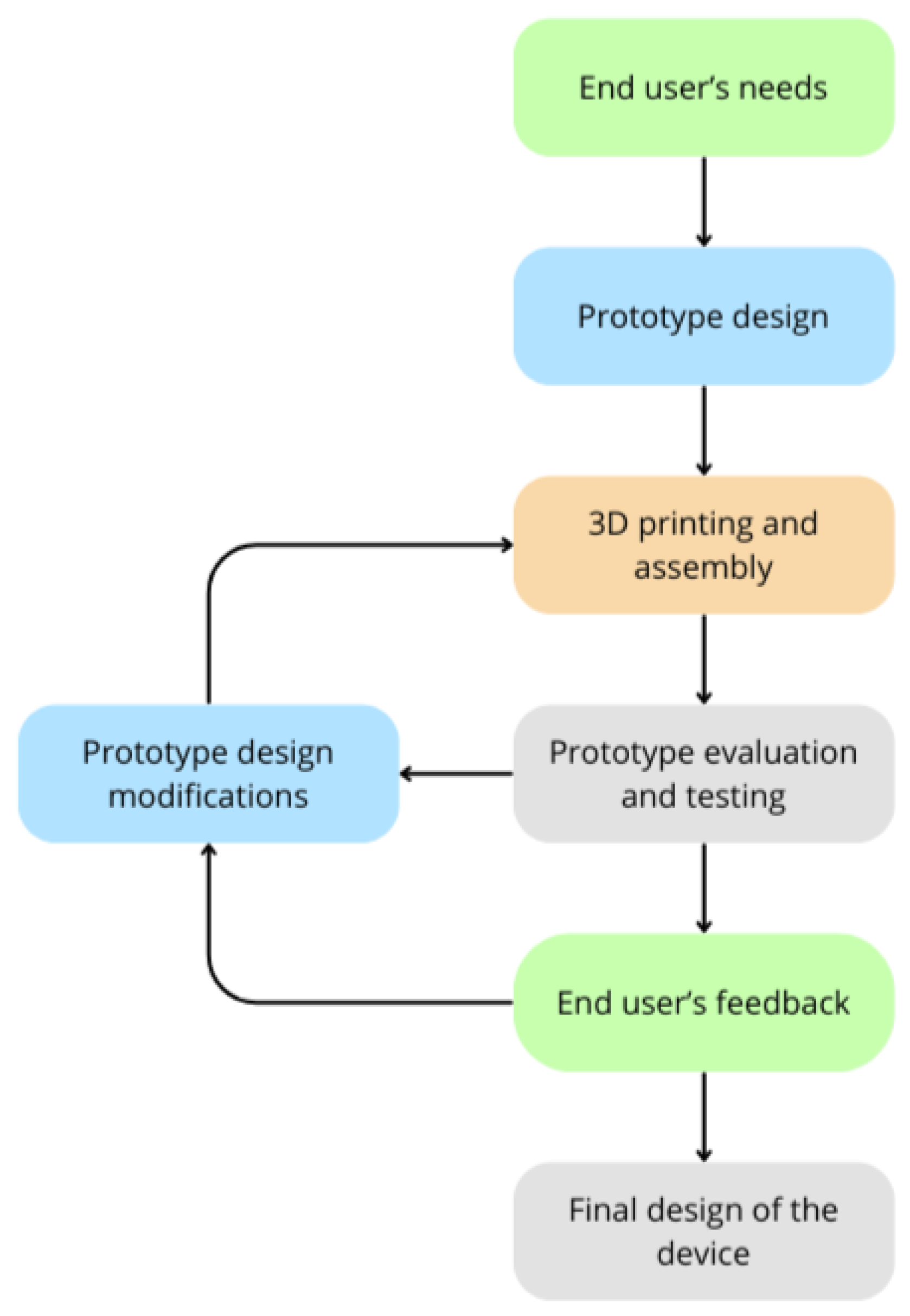
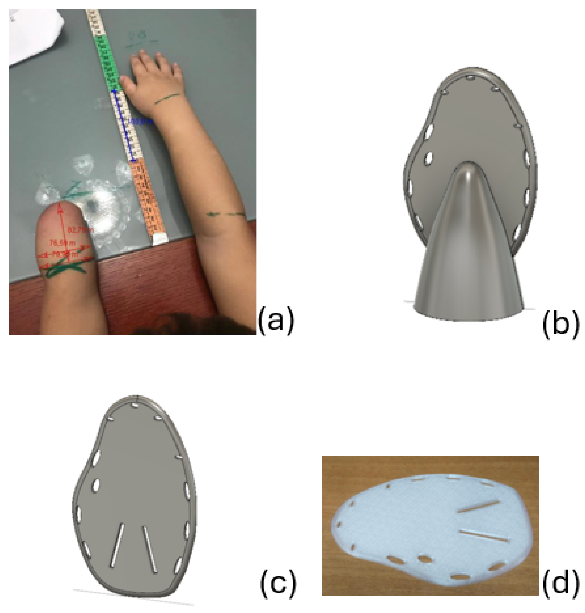
2.1. User-Centered Approach

A closed and constant collaboration with the end user is essential in the design and production of the devices. The following diagram illustrates the user-centered approach (Figure 1).
The user is directly involved both before and after the design and printing of the device to ensure that the final product fully meets all their requests and needs, which depend on their specific disability and personal preferences. The starting point is the specific need of the user and the definition of the type of device to be designed. This is followed by a second step that is crucial for fully personalizing the device: obtaining the measurements of both upper limbs. The measurements are provided by the parents of the final user, in the case of a child, or by the end-user themselves, in the case of an adult, following specific instructions provided by Io Do Una Mano (webpage: https://www.iodounamano.org/ accessed on 15 October 2024). In addition to filling out the template, the family of the applicant (or the applicant themselves) must also send photographs to the designers, adhering to the following guidelines outlined in a manual provided by Io Do Una Mano:
  • Draw lines around the wrists and elbows to make it easier to identify their position in the photograph;
  • If an elbow-operated device has been requested, also trace a line on the widest point of the biceps;
  • Extend the arms parallel to each other on a flat surface (such as a wall, the floor, or a table), placing a measuring tape at the center between the two arms;
  • Take photographs in the positions indicated by the examples shown in the manual.
These photographs are then analyzed with the open-source software Tracker, a free video analysis and modeling tool built on the Open Source Physics (OSP) Java framework [14], which allows the extraction of limb measurements from the photographs and the comparison with those provided by the family/user.
Once the personal needs of the end user have been defined and their measurements obtained, it is possible to proceed to the design and, then, the 3D printing and assembly steps, which will be described in detail in the following section. After these steps, a prototype of the device is available and needs to be assessed.
Before delivering the device to the end user, the quality of the printed object is evaluated to ensure the absence of defects in the material due to the shape of the object or the printing methods. Once any issues immediately present after printing have been resolved, one or more prototypes are sent to the user, who can use the device(s) for about 20 days. They can then provide feedback, especially regarding the adequacy of the device size and its functionality, to highlight any gaps or problems that may arise during use, or simply identify the best version among different prototypes. The final device is then provided to the user after another 15–20 days.
Continuous collaboration and ongoing communication with the user allow for guided modifications, which, in turn, lead to a personalized solution based on the needs and preferences of the end user. Contact with the user is also maintained after the device has been delivered to assist with assembly or maintenance if needed, and to follow up on new requests.

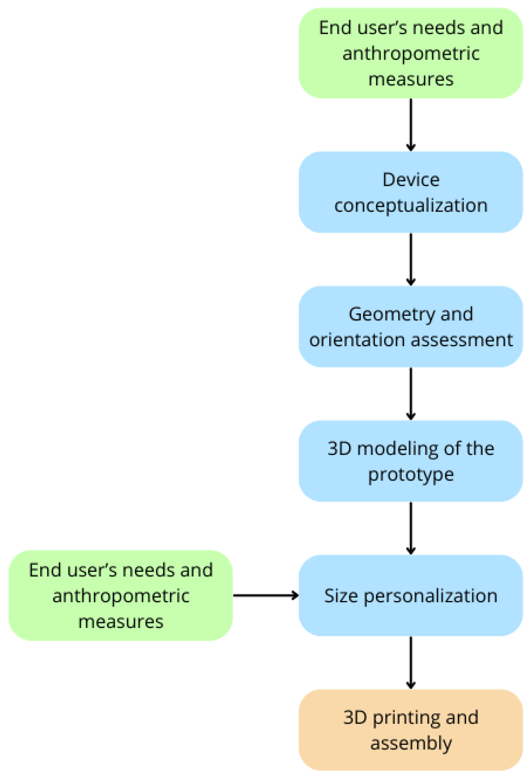
2.2. Prototype Design Process

The design process of the prototype is detailed in the blue blocks in Figure 2.
If a suitable model is not already available online (on the e-NABLE hub), the process moves on to the conceptualization of the device. In this phase of the design process, a 3D model is created in the Fusion 360, 2024 version (Autodesk, San Francisco, CA, USA) software environment to visualize the final appearance of the device. This may not necessarily correspond to the shape that the various pieces will have during printing, since it may be further modified through different post-printing processes, e.g., thermoforming. This step is useful to understand the functionality of the device once printed and assembled. When 3D modeling the prototype, thus defining the geometry and the orientation of the parts to be printed, the following aspects must be taken into account:
  • Mechanical properties. The goal is to make the assistive device as durable as possible through the optimal geometry of the parts that make up the prototype. If this evaluation is not done correctly, there is a risk of breakage of the assistive device itself.
  • Printability. The main objective is to reduce the need for support structures during printing [15]. There are several reasons to aim for as few supports as possible: It reduces print time, requires less post-printing processing, uses less material, and, thus, reduces the overall production costs of the assistive device.
  • Delamination. This phenomenon is defined as the separation between layers and it can occur during the printing process if the printer parameters, especially the material temperature and cooling speed, have not been properly set. However, the delamination phenomenon can also occur after the printing process and depend on the orientation of the layers: In this case, initially, the layers adhere well, but the application of forces in certain directions causes them to detach from each other. This problem can be avoided by reconsidering the shape and orientation of the printed object’s parts with respect to the print bed to ensure better mechanical properties.
  • Ease of assembly. In case the device is made up of two or more pieces, the goal is to make it as easy as possible to assemble once the parts are printed.
After considering these aspects, we move on to the actual modeling phase of the prototype, where the parts are designed to be printed by using the CAD software Fusion 360. Fusion 360 proves to be particularly suitable for engineering applications, as it is based on a parametric approach to 3D design: This allows for the quick adaptation of each model to fit individuals with similar disabilities and needs but with different anthropometric measures. This also maximizes the customizing potential offered by 3D printing technology without requiring excessive time and effort.

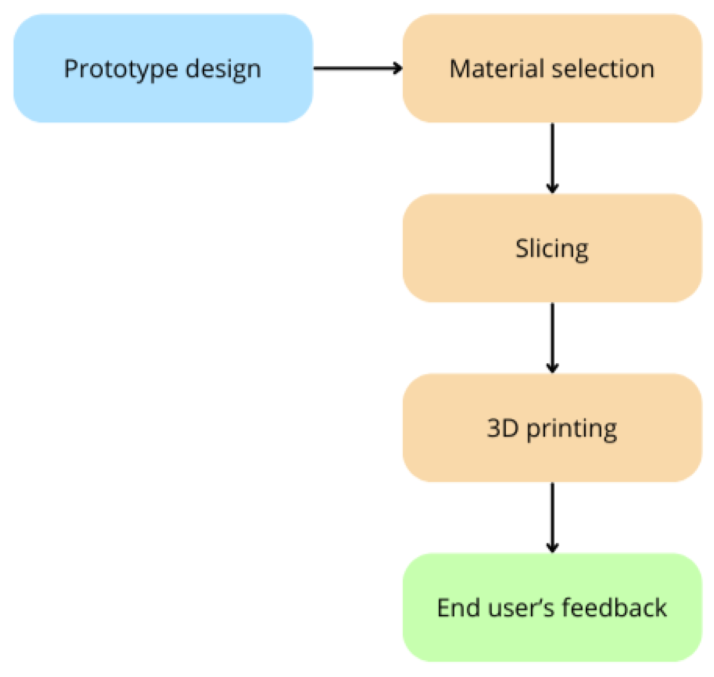
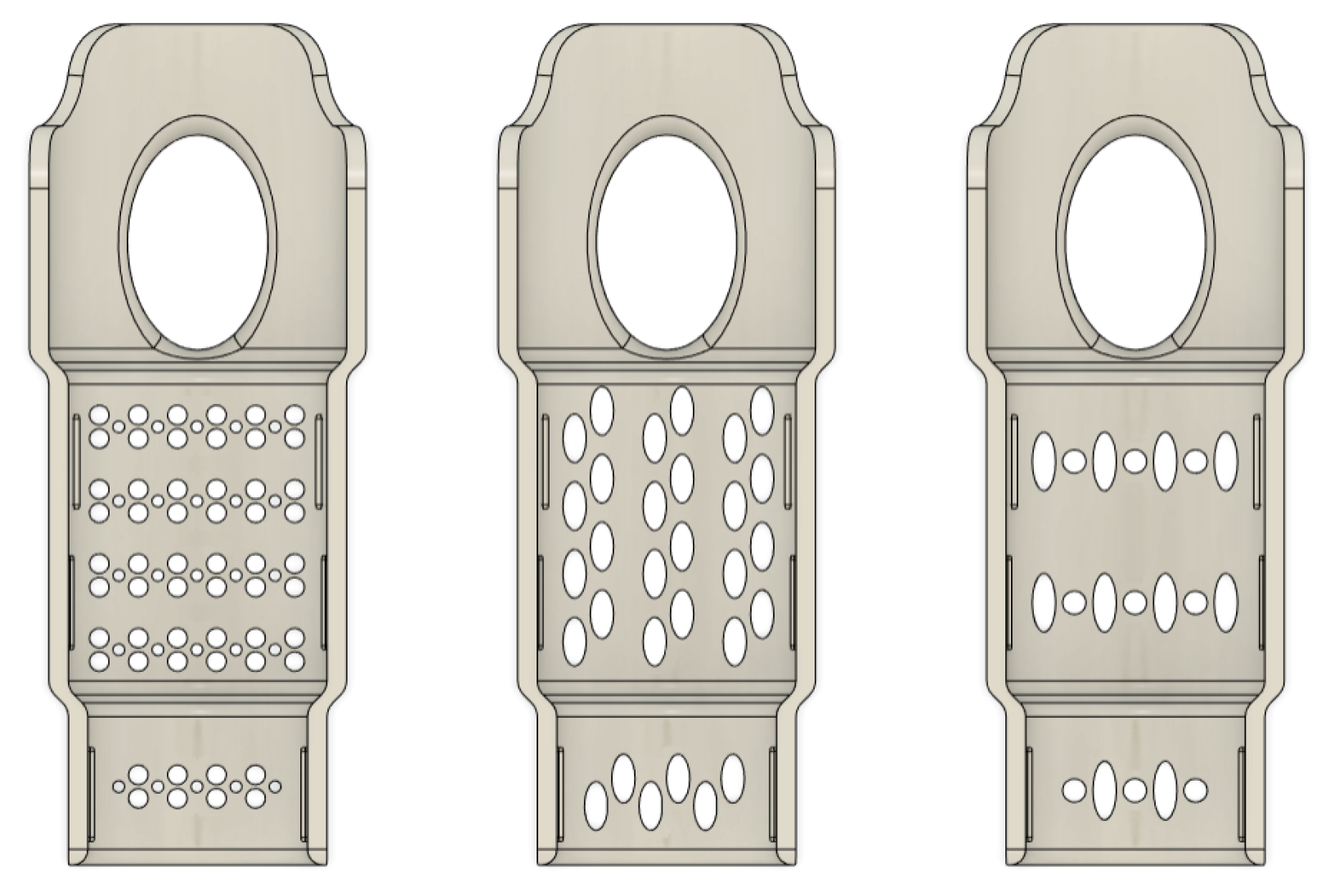
2.3. 3D Printing of the Prototype

The 3D printing process consists of three steps: material selection, slicing, and printing (orange blocks in Figure 3).
As for the material selection, the materials used within the scope of this work are the following:
  • Polylactic acid (PLA) was chosen for its biocompatibility and non-toxic properties, which are essential to avoid adverse reactions when in contact with the skin. Specifically, the LATIGEA filament from LATI 3D (LATI 3D, Vedano Olona, Italy) was used. It is a PLA stabilized against hydrolysis and UV radiation, a feature that makes it particularly suitable for outdoor use. Additionally, this material can undergo a crystallization process through baking, enhancing its mechanical strength and making it resistant to high temperatures (up to 100 °C).
  • Thermoplastic polyurethane (TPU) is an elastomer that combines the properties of thermoplastics and rubbers due to its alternating rigid and flexible segments. The elasticity of TPU depends on the proportion of these two types of chemical sequences [16]. This material was chosen for its high resistance to impacts, wear, abrasion, and cuts.
  • Polypropylene (PP) was selected for its durability and mechanical strength, and it is also particularly lightweight due to its low density [17]. The LATENE filament from LATI 3D was used, which is a PP filament with antibacterial additives. It is resistant to high temperatures (up to 100 °C) and resistant to hydrocarbons, acids, and strong bases. These characteristics make this material well-suited for chemically aggressive environments, such as a pool water environment.
  • Polyethylene terephthalate glycol (PETG) was chosen for its mechanical properties and thermal resistance. Specifically, recycled filament from LATI 3D was used, which is derived from post-industrial waste that does not face contamination issues like post-consumer waste.
The slicing software we used to create the GCODE files is PrusaSlicer version 2.7.1 (Prusa Research, Prague, Czech Republic), an open-source software associated with the Prusa printers (Prusa Research, Prague, Czech Republic). Several different 3D printers were used in the scope of this work: Sharebot Q (Sharebot, Nibionno, Italy) and Prusa MK4S and Prusa MK3S (Prusa Research, Prague, Czech Republic). To produce the devices presented in this paper, a layer height of 0.2 mm was used, which offers an excellent compromise between print quality and time. We chose the cubic infill pattern, as it provides mechanical strength in multiple directions. Finally, the compensation was set to zero to achieve better adhesion to the print bed.

3. Results

3.1. Swimming Aid

The request for a device suitable for swimming came through a questionnaire sent by Io Do Una Mano to the families of children who had previously received an upper limb hand device. The questionnaire was designed to assess the satisfaction and usage level of the devices provided and to encourage potential requests for functional devices that would assist in recreational and sports activities.
A child aged 6–7 with a disability below the elbow requested this device. Following the instructions from the Io Do Una Mano manual, the parents measured the arm and sent photographs to be analyzed using the software “Tracker” (2023 version) (Figure 4a).
The inspiration for the shape of this device was drawn from swimming paddles commonly used by swimmers during pool training. The initial prototype design features a funnel-shaped socket where the limb is inserted, and a paddle with holes (Figure 4b). These holes serve to reduce water resistance and enable the swimmer to move by applying less force. This aspect is particularly significant, especially considering that a limb affected by disability tends to have less developed musculature. However, this initial design has two issues:
  • There is no stable way to securely attach the socket to the limb.
  • The socket and the paddle need to be printed with layers oriented perpendicularly to each other, meaning separately. There is no way to later combine the two parts.
The assembly problem was not easily solvable and for this reason the socket was removed entirely, and the paddle was modified, devising an alternative way to wear the device: Two slots were added to replace the socket, through which a neoprene band is threaded to function as a binding system. The band guarantees a firm hold on the residual limb thanks to its size, and for older children and adolescents, a model with a second set of slots for adding an extra neoprene band was created. For this device, the best choice of material is the LATENE PP filament, as it is suitable for use in the pool due to its resistance to aggressive chemical environments. However, this material proved challenging to use due to its poor adhesion to the print bed. Some possible solutions to this problem include the following:
  • Using glue on the print bed;
  • Applying 3M (3M, Saint Paul, MN, USA) double-sided adhesive tape on the print bed;
  • Placing adhesive PP tape on the print bed;
  • Using a glass print bed.
The first three options did not yield satisfactory results. Therefore, the only viable option appeared to be replacing the traditional print bed with a glass one. Unfortunately, within the scope of this work, we did not have the opportunity to use it. However, we made initial assessments of the prototype by printing a version in PETG (Figure 4d).

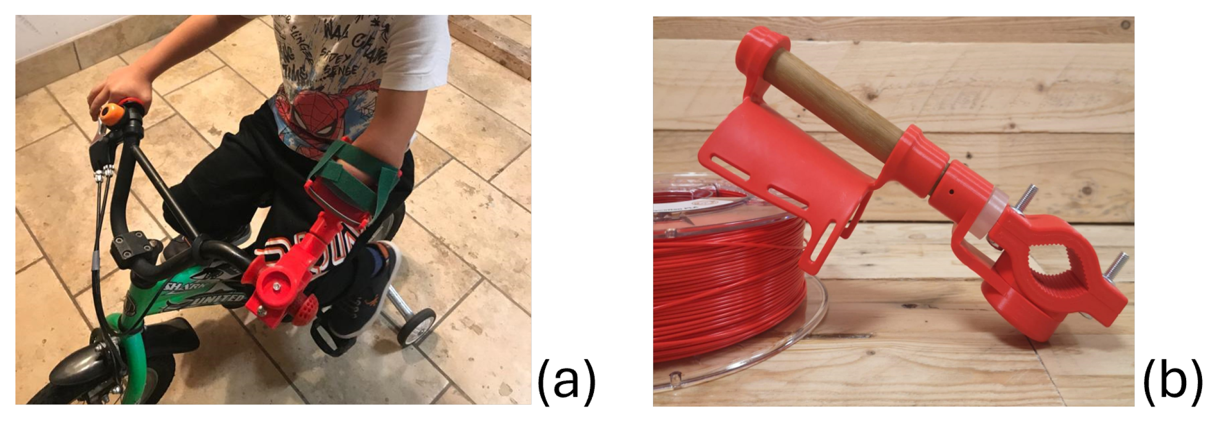
3.2. Non-Binding Bicycle Aid

The request for the first bike aid came from a child who had an arm disability below the elbow Figure 5a and had already received a prosthetic “hand” aid for grasping objects.
The child wanted to learn to ride a bicycle, and the “hand” aid was not suitable because it did not allow him to keep the handlebars gripped stably and securely. The child wanted a device enabling him to control the bicycle handlebars and make turns without the aid moving too much and causing him to lose his balance. In response to this request, a model that consists of a part attached to the bicycle handlebar on one side and a support for the residual limb on the other side was designed (Figure 5a). This tool, as opposed to the one described in the next chapter, is fixed: It is not possible to move the arm left and right or up and down, which would decrease stability. The user puts the arm over the arm support, secures it with velcro strips, and can then control the movements of the handlebar.
We separately printed the following parts: the hook for the handlebar, the residual limb support cup, and the curved piece to join the hook for the handlebar and the cup. The arm support was printed flat and, then, was thermoformed to obtain the concave shape. The components that are attached to the handlebar are assembled using screws and attached to the support through a wooden cylinder, providing greater strength and stability to the device (Figure 5b).The printed parts were made in PLA.

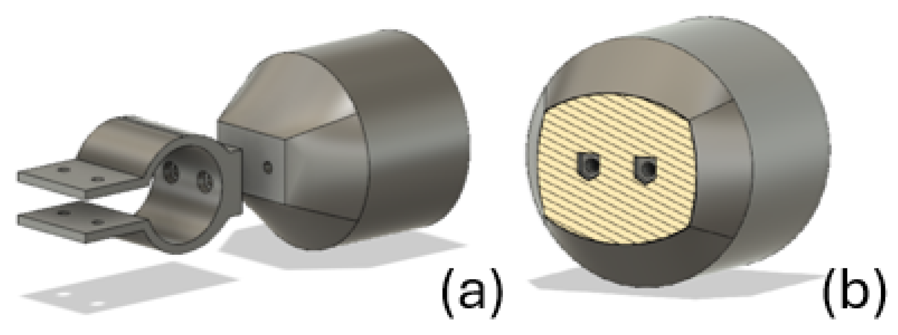
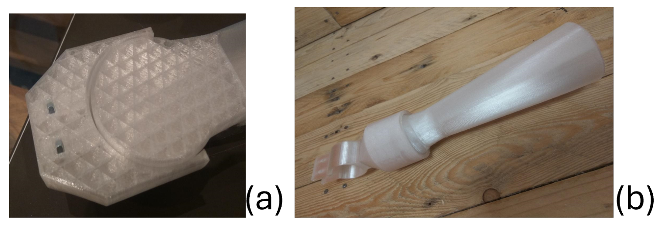
3.3. Binding Bicycle Aid

The request for this bicycle aid was directly made to Io Do Una Mano by the family of a child who had previously been provided with the non-binding bicycle aid described in the previous chapter. The request for a new device was made for the following reasons:
  • The dimensions of the first device were no longer adequate, as the child had grown, and the measurements of his arm had changed since the previous request was made. The new measurements were provided by the parents, who also took some photographs that were used for further analysis with the Tracker software.
  • The child wanted to learn to ride a bicycle without training wheels. With this system, the child could remove the arm from the support as the constraint did not offer excessive resistance. To increase his sense of security and control over the bicycle, he and his parents requested a device that completely encloses the arm, limiting its motion.
  • The velcro system might be impractical for a young child, as they would need assistance from their parents to secure the device.
For these reasons, a more secure and simultaneously easier- and quicker-to-wear device was requested. Starting from the end user’s needs, an initial model of the binding bicycle aid was designed (Figure 6).
The most significant modifications made to the initial prototype model were made to part A, which was divided into two parts to enable printing them with an optimal orientation. In the second version (Figure 7), the two components are attached using a pair of screws and nuts.
This option was chosen over the thermosetting resin bonding approach for several reasons: to minimize post-print processing, due to the wider availability of materials, and for ease of assembly and disassembly, which can also be performed by the family if and when necessary. Figure 7 describes the two components that are used to attach the device to the handlebar: The hook piece (Figure 7a) is attached to the bicycle handlebar, while the connecting piece (Figure 7b) functions as a bridge between the handlebar hook and the conical support for the residual limb.
The handlebar hook includes two recesses that serve as enclosures for the screw heads, preventing them from extending toward the bicycle’s handlebars. The cross-sectional view of the connecting piece highlights the cavities in which the nuts are inserted during the 3D printing of the device, as will be elaborated in greater detail later. Regarding piece B, which is the conical support for the residual limb, the goal was to design it in such a way that it could be easily inserted into the spherical cavity of the connecting piece. To achieve this, the initial design was modified by introducing a “cut” in the sphere of the conical support. This alteration would ideally make it flexible enough to be stably inserted by passing it through the constriction of the cavity in the connecting piece after printing the components of the device.
To test this solution, the connecting piece and part of this version of the conical support were 3D printed. However, when attempting to insert the sphere into the cavity, the sphere ended up breaking: This version was not functional. The prototype design was then reverted to the original version featuring the solid sphere for the conical support. However, a change was made in the approach to the 3D printing process: The conical support is now printed and already inserted into the spherical cavity of the connecting piece.
For the creation of the prototype of the binding bicycle aid, a PETG filament was chosen. The printing process for this device lasted 18 h, including a pause after 10 h to insert the nuts into their designated slots (Figure 8a).
The printing orientation for the connecting piece and the conical support made support structures necessary. The finished prototype is shown in Figure 8b.

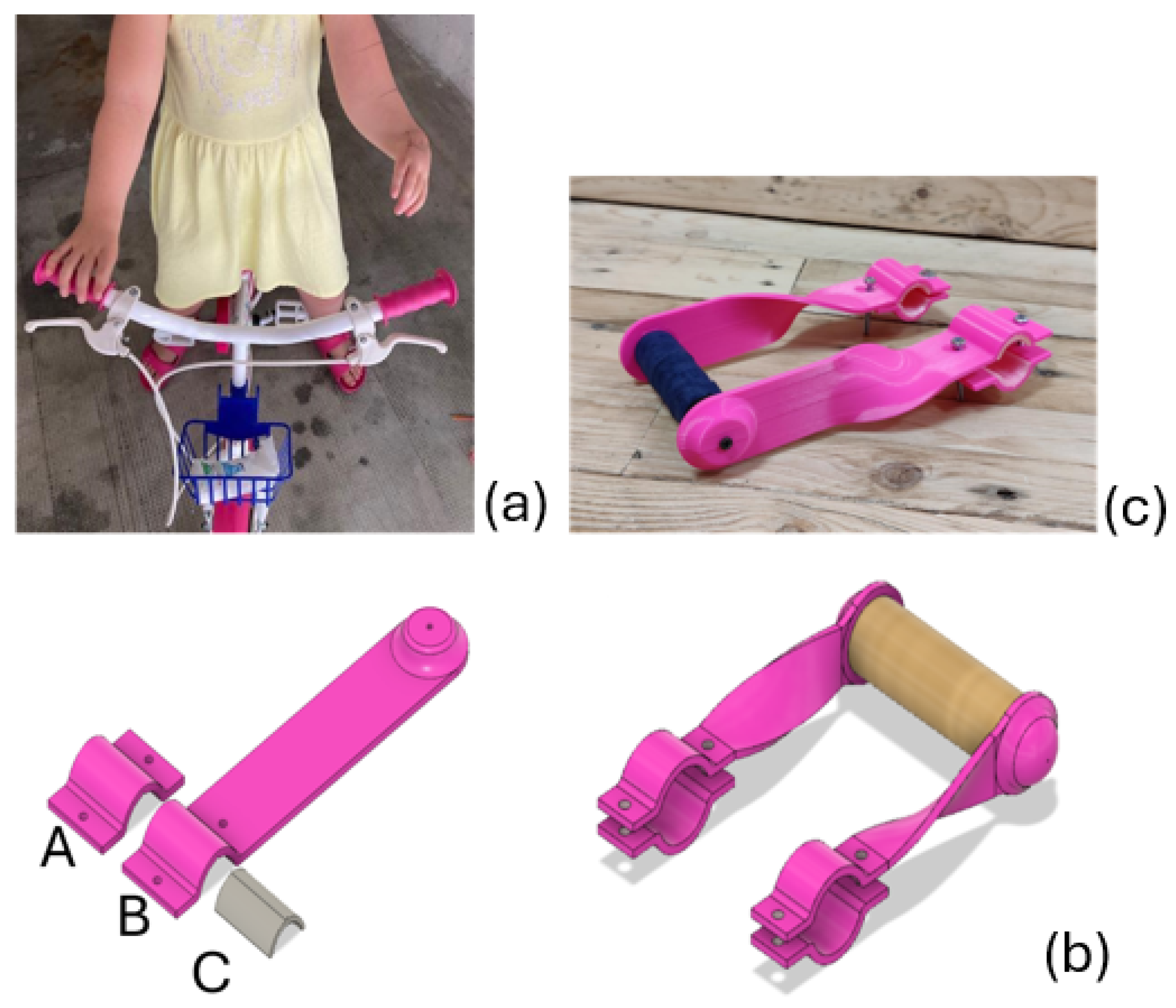
3.4. Handlebar Extender Bicycle Aid

The request for this device came directly to the Io Do Una Mano association from the family of a child who had never received any device or prosthesis before. The child has a different disability compared to those of the individuals considered so far: both of her hands are present and functional despite the absence of thumbs, while her left limb lacks a forearm (Figure 9a).
The request for a bicycle aid was made because the difference in limb length caused the child to lean forward on the left side, assuming an asymmetrical and incorrect posture while using the bicycle, which could potentially have negative consequences on her spine. To create a device suitable for the child, the parents followed the measurement instructions provided in the Io Do Una Mano manual and took photographs, which were subsequently analyzed using Tracker.
Based on the end user’s needs and measurements, the initial model in Figure 9b of the device was created. It consists of three different pieces:
  • Piece A is the smaller pink piece;
  • Piece B constitutes the handlebar extension;
  • Piece C is the gray curved piece.
In contrast to the devices described in the previous chapters, the final appearance of the components of this device and their shape during printing are quite different from one another:
  • Piece B was printed flat to achieve the best possible orientation of the print layers. By overlapping parallel planes, weak points are avoided, resulting in improved mechanical properties. The curvatures are formed afterward through thermoforming.
  • The positioning of the three parts on the printer bed was determined considering the print orientation and, consequently, the layering direction of the material. This orientation enhances resistance to usage, particularly in preventing layer delamination.
  • To enhance friction between the device and the bicycle handlebar, the width of the parts in contact with it (pieces A and B) was increased, and piece C was introduced. This part features a textured surface on the inner side; it also includes a wedge on the opposite side to securely fit piece C into pieces A and B, which have a corresponding cavity.
The device is composed of two copies of pieces A and B and four copies of piece C. Pieces A and B are printed using the LATIGEA PLA filament from LATI 3D, while piece C is printed in TPU with a Shore Hardness Scale value of 85A.
Once all the parts constituting the device are printed, the first step is thermoforming pieces B to replicate the shape of the 3D design of the model: A heat gun was employed to heat the PLA to 50 °C and render it malleable. This was possible without causing the degradation of the material since the chosen PLA filament is resistant to temperatures up to 100 °C.
Subsequently, the device is assembled by affixing a wooden cylinder, serving as the handlebar, using nails. This wooden cylinder is then enveloped with tennis racket grip tape to offer a soft surface for the child to grasp. The final result is shown in Figure 9c.
The family was also provided with the necessary materials (nuts and screws) to mount the device on the bicycle handlebar. Additionally, after the delivery of the device, ongoing communication was maintained to provide the necessary support for the assembly and maintenance of the device.

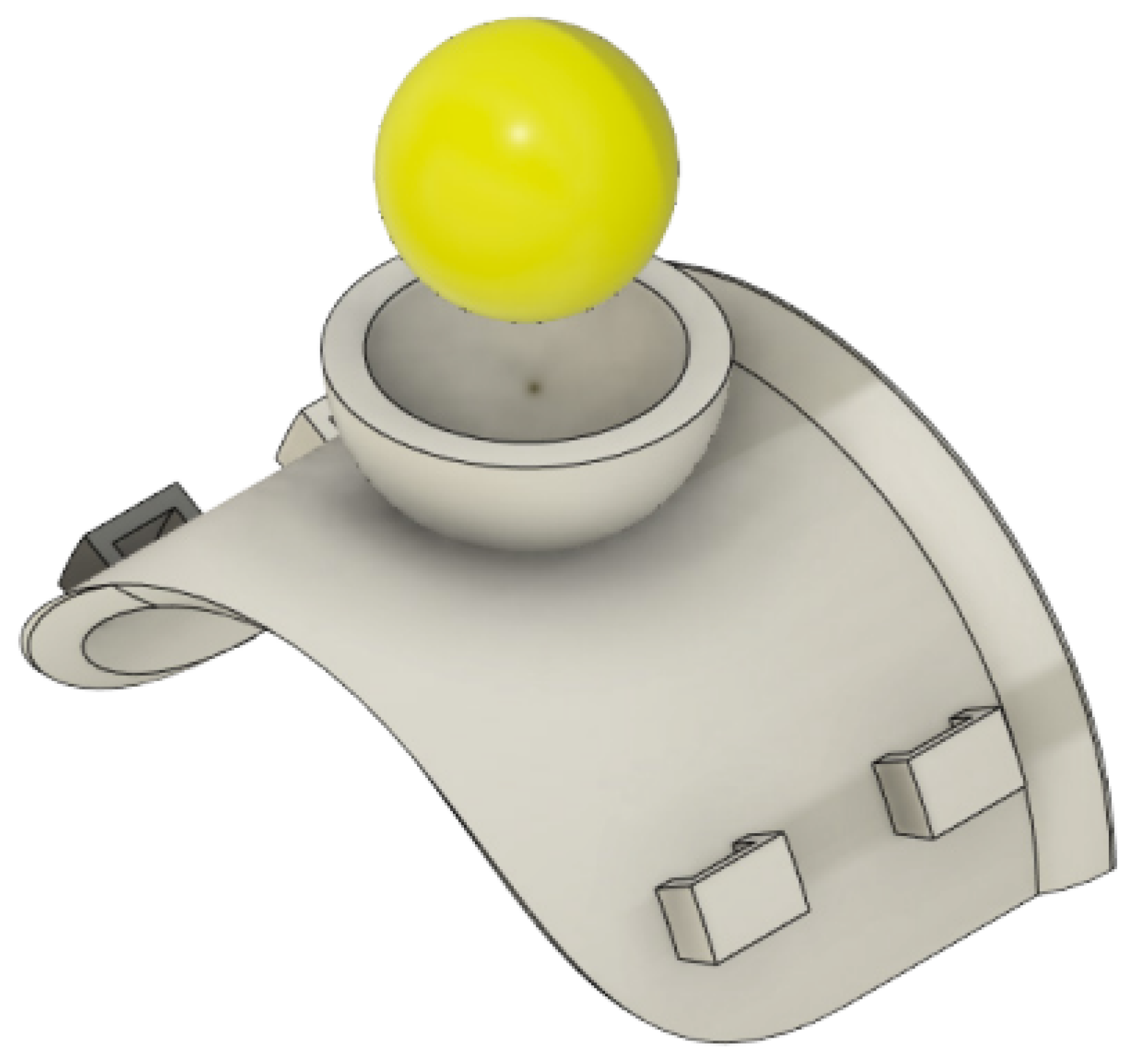
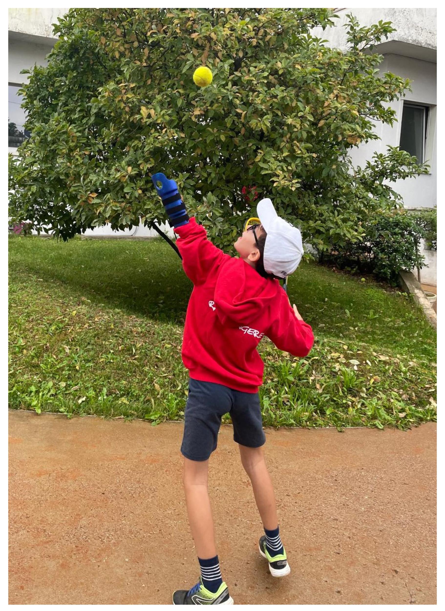
3.5. Tennis Serve Aid

For this device, we took inspiration from the one produced by Koalaa (https://www.yourkoalaa.com/gymandsport accessed on 1 October 2024). The request for this device came from a child who had previously received two hand devices and a non-binding bicycle aid.
Parastanding-tennis athletes employ different strategies for throwing the ball when serving:
  • Holding the ball and the tennis racket in the same hand;
  • Holding the racket under the underarm while throwing the ball;
  • Throwing the ball using the racket;
  • Holding the ball between the bicep and the forearm.
Each of these strategies can be effective, but they all present some problems based on the different abilities of the athlete. In this case, the child used the last strategy; however, he struggled with strength and precision when throwing the ball for the serve. Two different solutions were designed. The first is based on the strategy the child had previously adopted, while the second design aimed at imitating the traditional tennis serve.
The first design consisted in a wearable cup where the tennis ball would be placed and held by the forearm while lifting the ball before the throw (Figure 10).
However, this design was eventually abandoned because of the size of the child’s arm, which was too thin to enable an appropriately sized cup without being excessively intrusive. Furthermore, this aid would not improve the strength of the ball throw.
The second design consisted of an extension of the arm, ending in a cup for holding the ball. An important aspect to take into consideration for this solution is the length of this device: it has to be long enough to help the child in throwing the ball more easily, but not too long as to become a burden while playing. Regarding the cup, two versions were designed:
  • Open cup: There are no other supports around the ball, which makes the device less invasive by avoiding coming in contact with the legs and sides of the child; a drawback is the reduced control on the ball (Figure 11).
  • Closed cup: In this case, walls were added to the sides of the cup, enabling a better control while lifting the ball (Figure 11).
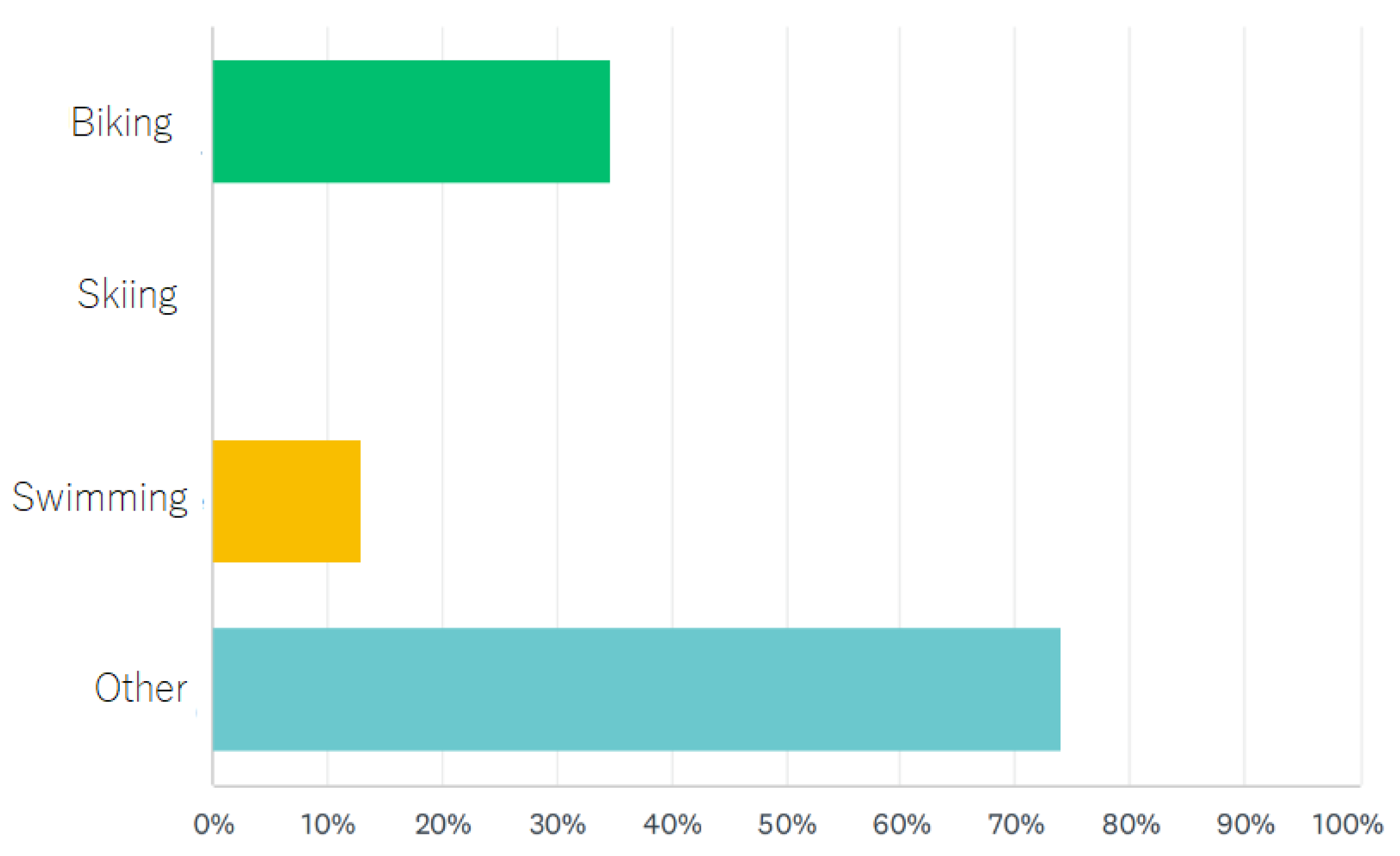
The device was printed using PETG as opposed to PLA, since it has better mechanical properties, as well as heat and sun exposure resistance.
After the first use, the child was very satisfied with the device (Figure 12). In particular, he found the tactile feedback from the ball touching his residual arm to be very useful, especially while getting used to the device. He also was satisfied with the comfortability of the device while playing, with only the proximal ending of the aid slightly bothering him. This problem was solved by rounding the edge in design.
Another improvement was made by adding small holes on the part in contact with the arm in order to allow perspiration (Figure 13).

4. User Feedback

The end users that have received one or more devices over the years are a total of 50 and have been interviewed through a set of questions to gauge their satisfaction level after one month of the delivery of the device. In this work, we present the results of 23 responses to the questionnaire. The short survey sent to the end users (including the ones of the case studies presented in this work) was based on multiple choice and open questions:
  • How often is the aid being used? (i.e., never, 2/3 times a week, every day, other);
  • Is the aid you are using now still suitable or has it become small? (i.e., it is fine, it is small, other);
  • If Io Do Una Mano were to develop new physical activity aids, which ones would be useful? (i.e., cycling, skiing, swimming, other);
  • How could the Io Do Una Mano service be improved? (open question);
  • What does he/she use the aid for? (i.e., going to school, playing, for physical activity, eating, other);
  • What customization would he/she like to have in the next assistive device? (open question);
  • What sport/hobby does he/she practice? (open question).
Firstly, the end users were asked how often they use the device, and 39.13% of the users answered that they wear it each time they perform the specific task or action they requested the aid for; 47.83% wear it 2/3 times per week (Figure 14).
Secondly, the users were asked whether they the aid they received was still suitable, and 86.96% answered affirmatively; only 13.04% answered that it became small (Figure 15).
Finally, the users were asked what new sports activities they performed and whether they were interested in receiving a new device. Five of the children requested the same model of the device they previously received with new updated measurements. Fifteen children requested one or more new models to perform specific activities, such as cycling (11), swimming (4), playing musical instruments (2), weightlifting (2), basketball (1), writing and painting (1), kayaking (1), cutting grass (1), and tennis (1) (Figure 16).
The responses to the question “How could the Io Do Una Mano service be improved?” were all positive. Examples of feedback (translated from Italian) include suggestions such as “You are already doing a great job”, “By making a greater variety off devices”, and “By designing additional devices”. The responses demonstrate strong user satisfaction and reflect an interest in further collaboration and the development of new solutions.
For the second open question, “What customization would he/she like to have in the next assistive device?”, 10 out of 23 responses did not specify preferences. Among the remaining 13 responses, suggestions included incorporating specific colors, animals, and fictional characters into the design. These findings highlight the significance of full customization, a feature facilitated by 3D printing technology, in meeting the preferences and expectations of the end users.
Responses to the question “What sport/hobby does he/she practice?” often aligned with requests for specific functional devices identified through the question “If Io Do Una Mano were to develop new physical activity aids, which ones would be useful?”. This alignment suggests that users’ hobbies and interests are closely linked to their expectations for new assistive solutions.
Lastly, regular monthly check-ins with the end users ensure consistent communication, allowing the association to address maintenance needs, gather feedback, and adapt to emerging requirements or interests effectively.

5. Conclusions

In this paper, we described a general workflow for the design and realization of 3D-printed customized functional sport assistive devices. The most important aspect is involving the end user in all the key steps of the design, to accommodate the unique and specific needs dictated by their disability and also their personal preferences. These needs can change overtime, as was made particularly evident by the devices requested by the use cases illustrated in the previous chapter, both due to the rapid physical growth and the development of interest in new activities of the children involved. This work shows how 3D printing technology is greatly effective, cost-efficient, and not time-consuming in this kind of application.

6. Future Developments

New requests for sports aids are being sent to Io Do Una Mano, either to improve an existing aid or to develop a completely new prototype. In this regard, continuous contact is maintained with the users to develop the most functional and comfortable aid possible. More and more adults also request new aids through the Io Do Una Mano association to perform daily tasks and meet their design and aesthetic preferences. In this regard, new specific aids have been requested for biking, working out in a gym setting, and skiing. The aids in the production phase are for biking (particularly for MTB and downhill), gym workouts (to assist in weightlifting), and skiing (cross-country and downhill). In addition, thanks to the collaboration with the associations Raggiungere ODV and AISP (Italian Association of Poland Syndrome), meetings and events are organized where users can make requests for the development of new aids.

Author Contributions

Conceptualization, M.B. and J.S.; Methodology, M.B.; Validation, M.B., F.S., E.P. and M.C.; Formal analysis, M.B. and L.T.; Investigation, M.B., L.T. and F.S.; Resources, M.B. and L.T.; Data curation, M.B., L.T. and F.S.; Writing—original draft, M.B. and L.T.; Writing—review and editing, M.B., L.T. and M.C.; Visualization, M.B., E.P. and M.C.; Supervision, M.B., J.S., E.P. and M.C.; Project administration, M.B. All authors have read and agreed to the published version of the manuscript.

Funding

The work of the Unige team was supported by the European Union—NextGenerationEU and by the Ministry of University and Research (MUR), National Recovery and Resilience Plan (NRRP), Mission 4, Component 2, Investment 1.5, project “RAISE—Robotics and AI for Socio-economic Empowerment” (ECS00000035). M. Casadio is part of RAISE Innovation Ecosystem.

Institutional Review Board Statement

Based on “Regolamento (UE) 2016/679” (GDPR), this work does not require ethical committee approval because it does not refer to a research project but rather to a routine process. It describes the pipeline of routine work for an association, specifically as a by-product of the established procedures at the Io Do Una Mano association, without any modifications. Nothing has been added to the association’s pipeline for research purposes. Furthermore, all the data used are publicly accessible, as the association makes all details of the developed devices and the processes for creating them available to anyone who might need them. Finally, there are no identifiable data involved in this work, thus eliminating the risk of harm or privacy violations.

Informed Consent Statement

Informed consent and release liability were obtained from all subjects involved in the study.

Data Availability Statement

The original data presented in the study are openly available in IO DO UNA MANO Website at link: https://www.iodounamano.org/ (accessed on 15 October 2024).

Acknowledgments

We would like to thank LATI3D for providing the materials for printing and the associations Raggiungere ODV and AISP for recommending our association to their members.

Conflicts of Interest

The authors declare no conflicts of interest.

References

  1. Al-Dewik, N.; Samara, M.; Younes, S.; Al-Jurf, R.; Nasrallah, G.; Al-Obaidly, S.; Salama, H.; Olukade, T.; Hammuda, S.; Marlow, N.; et al. Prevalence, predictors, and outcomes of major congenital anomalies: A population-based register study. Sci. Rep. 2023, 13, 2198. [Google Scholar] [CrossRef] [PubMed]
  2. Oelmeier, K.; Schmitz, R.; Dera, I.; Plaßmann, M.; Braun, J.; Willy, D.; Sourouni, M.; Köster, H.A.; Steinhard, J.; Röpke, A.; et al. Congenital Limb Defects: A Retrospective Cohort Study and Overview of the Literature. Ultraschall Der Med. Eur. J. Ultrasound 2022, 44, e241–e247. [Google Scholar] [CrossRef]
  3. Wilcox, W.R.; Coulter, C.P.; Schmitz, M.L. Congenital limb deficiency disorders. Clin. Perinatol. 2015, 2, 281–300. [Google Scholar] [CrossRef] [PubMed]
  4. Maat, B.; Smit, G.; Plettenburg, D.; Breedveld, P. Passive prosthetic hands and tools: A literature review. Prosthet. Orthot. Int. 2018, 42, 66–74. [Google Scholar] [CrossRef] [PubMed]
  5. Toledo, C.; Leija, L.; Munoz, R.; Vera, A.; Ramirez, A. Upper limb prostheses for amputations above elbow: A review. In Proceedings of the 2009 Pan American Health Care Exchanges, Mexico City, Mexico, 16–20 March 2009; pp. 104–108. [Google Scholar]
  6. Ten Kate, J.; Smit, G.; Breedveld, P. 3D-printed upper limb prostheses: A review. Disabil. Rehabil. Assist. Technol. 2017, 12, 300–314. [Google Scholar] [CrossRef] [PubMed]
  7. Davids, J.R.; Wagner, L.V.; Meyer, L.C.; Blackhurst, D.W. Prosthetic management of children with unilateral congenital below-elbow deficiency. JBJS 2006, 88, 1294–1300. [Google Scholar] [CrossRef]
  8. Golea-Vasluian, E.; van Wijk, I.; Dijkstra, P.U.; Reinders-Messelink, H.; van der Sluis, C.K. Adaptive devices in young people with upper limb reduction deficiencies: Use and satisfaction. J. Rehabil. Med. 2015, 47, 346–355. [Google Scholar] [CrossRef] [PubMed]
  9. Parry-Hill, J.L.; Ashbrook, D.L. Challenges and Opportunities in DFO-AT: A Study of e-NABLE. 2016. Available online: http://scholarworks.rit.edu/article/1808 (accessed on 21 January 2025).
  10. Rahman, Z.; Barakh Ali, S.F.; Ozkan, T.; Charoo, N.A.; Reddy, I.K.; Khan, M.A. Additive manufacturing with 3D printing: Progress from bench to bedside. AAPS J. 2018, 20, 101. [Google Scholar] [CrossRef]
  11. Fink, C.; Diamond, Y. Prosthesis Options and Management in Upper Extremity Amputation. Oper. Tech. Orthop. 2023, 33, 101061. [Google Scholar] [CrossRef]
  12. Eime, R.M.; Young, J.A.; Harvey, J.T.; Charity, M.J.; Payne, W.R. A systematic review of the psychological and social benefits of participation in sport for children and adolescents: Informing development of a conceptual model of health through sport. Int. J. Behav. Nutr. Phys. Act. 2013, 10, 98. [Google Scholar] [CrossRef]
  13. Warburton, D.E.; Nicol, C.W.; Bredin, S.S. Health benefits of physical activity: The evidence. Cmaj 2006, 174, 801–809. [Google Scholar] [CrossRef]
  14. Jara, C.A.; Esquembre, F.; Christian, W.; Candelas, F.A.; Torres, F.; Dormido, S. A new 3D visualization Java framework based on physics principles. Comput. Phys. Commun. 2012, 183, 231–244. [Google Scholar] [CrossRef]
  15. Calderan, P. Stampa 3D: Il Manuale per Hobbisti e Maker; Number 8; Apogeo Editore: Milan, Italy, 2015. [Google Scholar]
  16. Sher, D.; Marinoni, D. Stampa 3D: Tutto Quello che c’e’da Sapere Sull’unica Rivoluzione Possibile; HOEPLI EDITORE: Milan, Italy, 2015. [Google Scholar]
  17. Bertolino, M.; Battegazzore, D.; Arrigo, R.; Frache, A. Designing 3D printable polypropylene: Material and process optimisation through rheology. Addit. Manuf. 2021, 40, 101944. [Google Scholar] [CrossRef]
Figure 1. Overview of the process. The green blocks represent the steps in which the end user intervenes directly in the process, the blue blocks represent the design and 3D modeling steps, and finally, the orange block represents the 3D printing and assembly step of the prototype.
Prosthesis 07 00017 g001
Figure 2. Prototype design process.
Prosthesis 07 00017 g002
Figure 3. 3D printing process.
Prosthesis 07 00017 g003
Figure 4. (a) Example of the pose for the photograph of the child’s arms to be analyzed with the Tracker software in order to obtain relevant measurements; (b) initial prototype design of the swimming aid, featuring a funnel-shaped socket and a paddle with holes; (c) third and final prototype design of the swimming aid; (d) swimming aid prototype printed with PETG filament.
Prosthesis 07 00017 g004
Figure 5. (a) Non-binding bicycle aid attached to the handlebar; (b) assembled non-binding bicycle aid with the wood cylinder and screws.
Prosthesis 07 00017 g005
Figure 6. Initial prototype design for the non-binding bicycle aid. Part (A) is mounted on the bicycle handlebar. Part (B) is the support for the residual limb.
Prosthesis 07 00017 g006
Figure 7. (a) Second version of piece A of the non-binding bicycle aid, consisting of a handlebar-hook piece and a connecting piece; (b) cross-section view of the connecting piece.
Prosthesis 07 00017 g007
Figure 8. (a) 3D printing process of the non-binding bicycle aid; (b) final prototype of the non-binding bicycle aid.
Prosthesis 07 00017 g008
Figure 9. (a) Handlebar extender bicycle aid; (b) initial prototype design of the handlebar extender bicycle aid and final shape to be achieved; (c) final prototype of the handlebar extender bicycle aid. Part A and B are mounted to the bycicle handlebar and support the wooden cylinder. Part C is printed in TPU and is placed between parts A and B and the handlebar to increase friction.
Prosthesis 07 00017 g009
Figure 10. Wearable cup where the tennis ball would be placed.
Prosthesis 07 00017 g010
Figure 11. Open (left) and closed (right) cup version.
Prosthesis 07 00017 g011
Figure 12. An end user during the final test of the tennis aid.
Prosthesis 07 00017 g012
Figure 13. Version with different styles of the perspiration holes.
Prosthesis 07 00017 g013
Figure 14. Representation of the answers to the following question: How often is the aid being used?
Prosthesis 07 00017 g014
Figure 15. Representation of the answers to the following question: Is the aid you are using now still suitable or has it become small?
Prosthesis 07 00017 g015
Figure 16. Representation of the answers to the following question: If Io Do Una Mano were to develop new physical activity aids, which ones would be useful?
Prosthesis 07 00017 g016
Disclaimer/Publisher’s Note: The statements, opinions and data contained in all publications are solely those of the individual author(s) and contributor(s) and not of MDPI and/or the editor(s). MDPI and/or the editor(s) disclaim responsibility for any injury to people or property resulting from any ideas, methods, instructions or products referred to in the content.

