Resilient and Sustainable Structures through EMI-Based SHM Evaluation of an Innovative C-FRP Rope Strengthening Technique


Abstract
1. Introduction
2. Proposed Innovation and Aim of the Study
3. Experimental Program
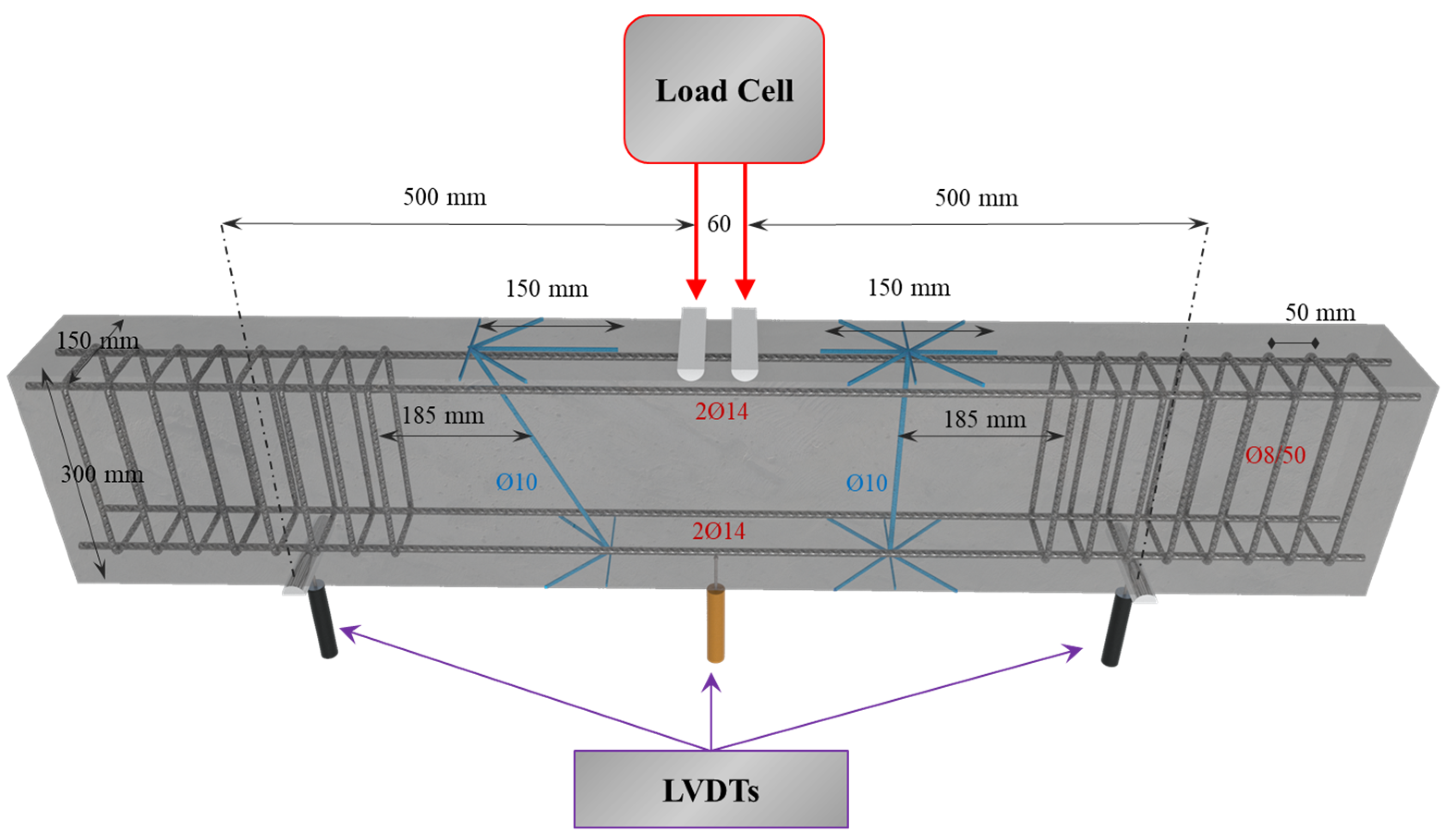
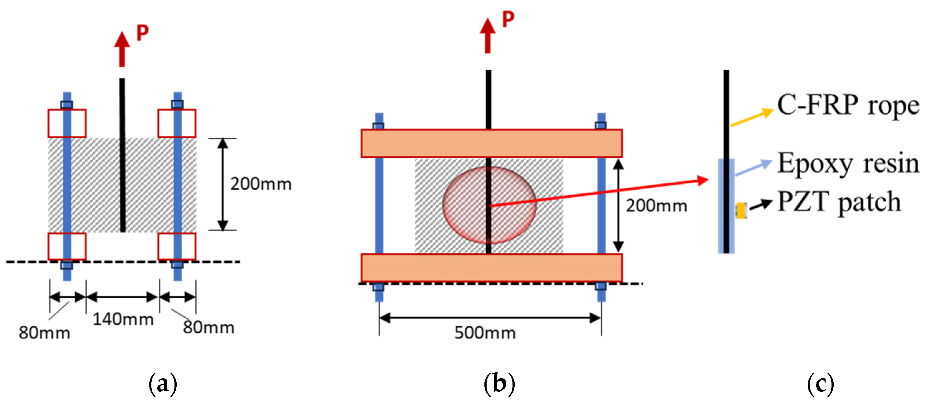
3.1. Characteristics of the Deep Beam
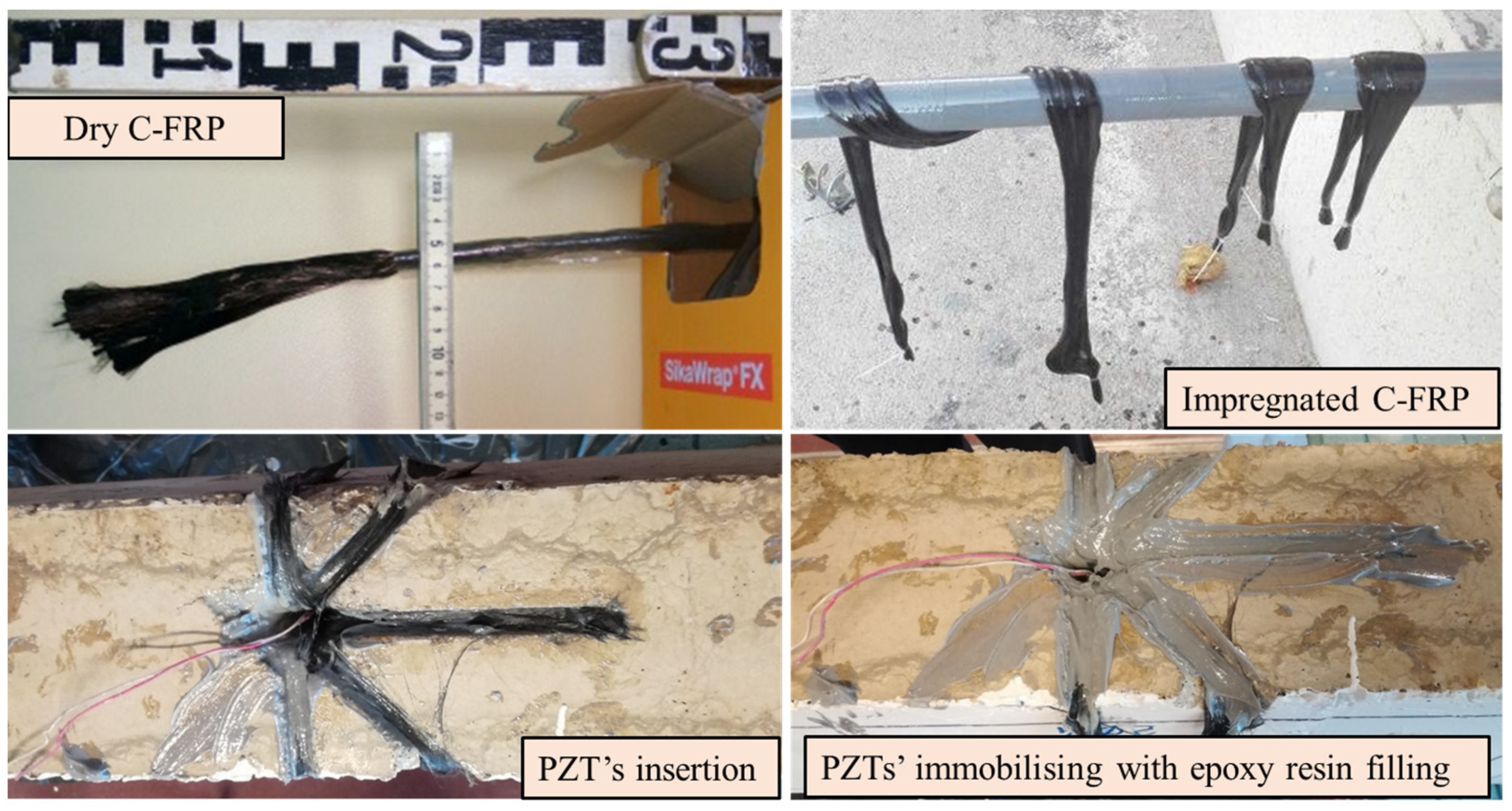
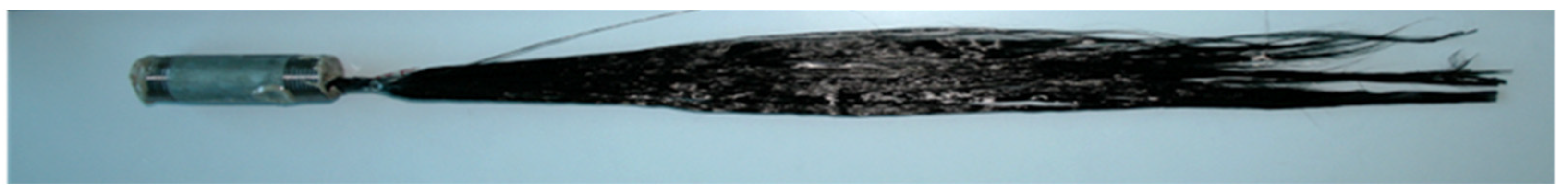
- Formation of the anchorage’s tassels and drilling of the holes to the beam’s web.
- Use of compressed air and a particular tool brush to remove the trapped dust inside the drilled holes.
- Epoxy resin impregnation of the rope following the manufacturer’s technical data sheet.
- Epoxy resin filling of the anchorage’s tassel grooves.
- C-FRP ropes and attached PZT-bonded insertion into the drilled holes.
- Filling of holes with epoxy resin to eliminate voids and enhance coherence among the embedded materials.
- Application of slight tension to the end of the ropes to achieve the final anchorage formation.
- Addition of more epoxy resin to the surface of the beams to achieve smoother grooves.
3.2. Materials
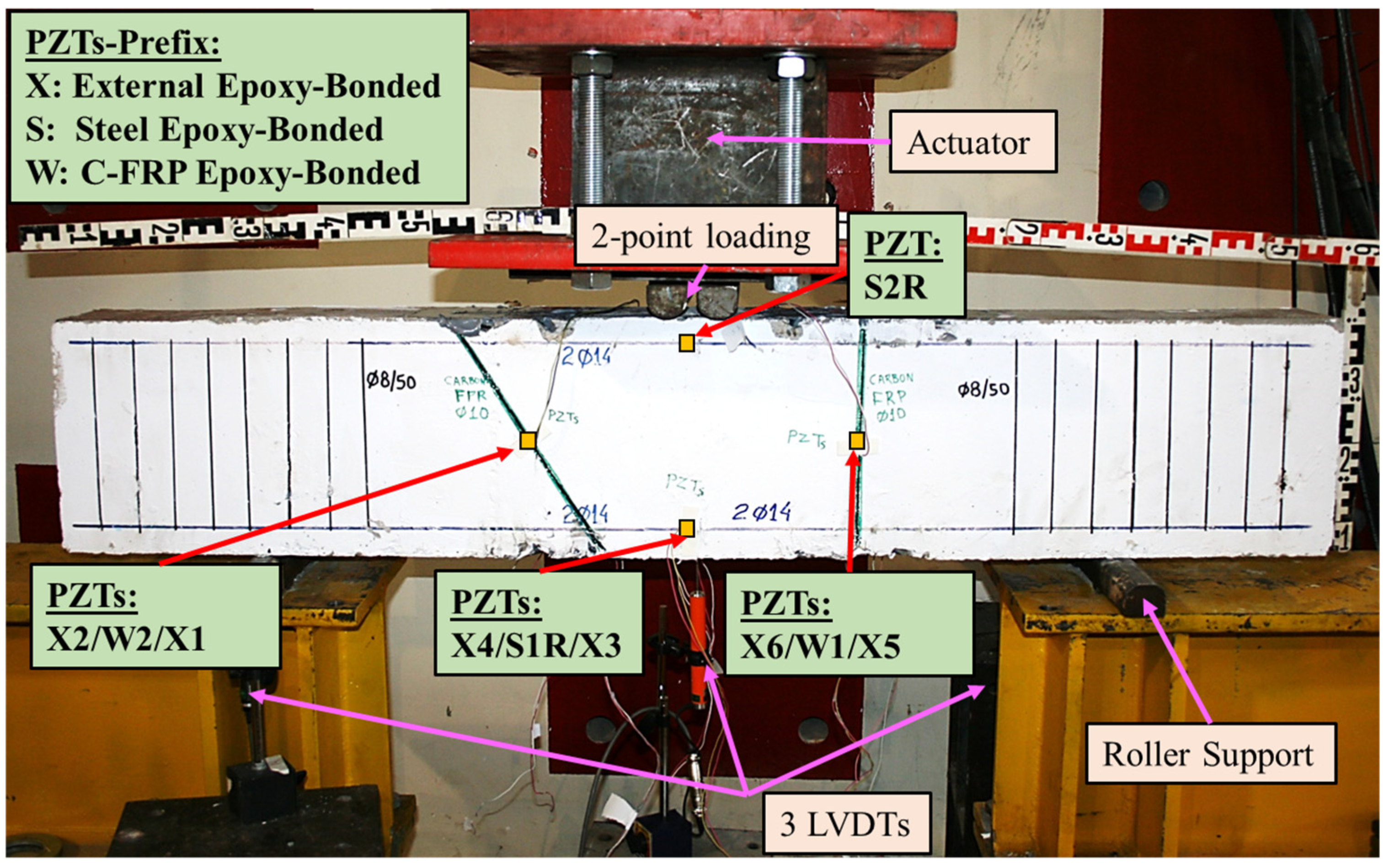
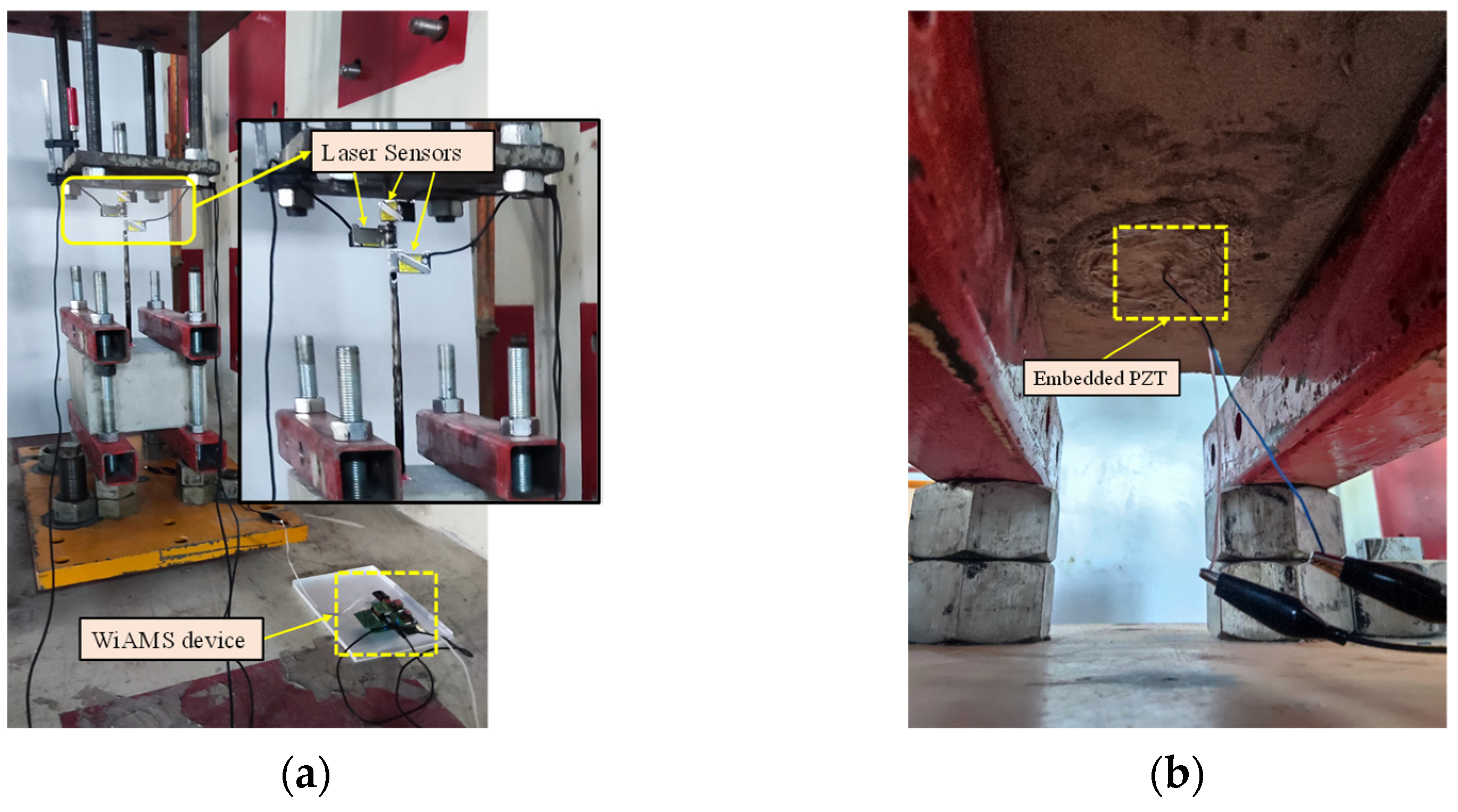
3.3. Test Setup
3.4. Electro-Mechanical Impedance (EMI) Technique
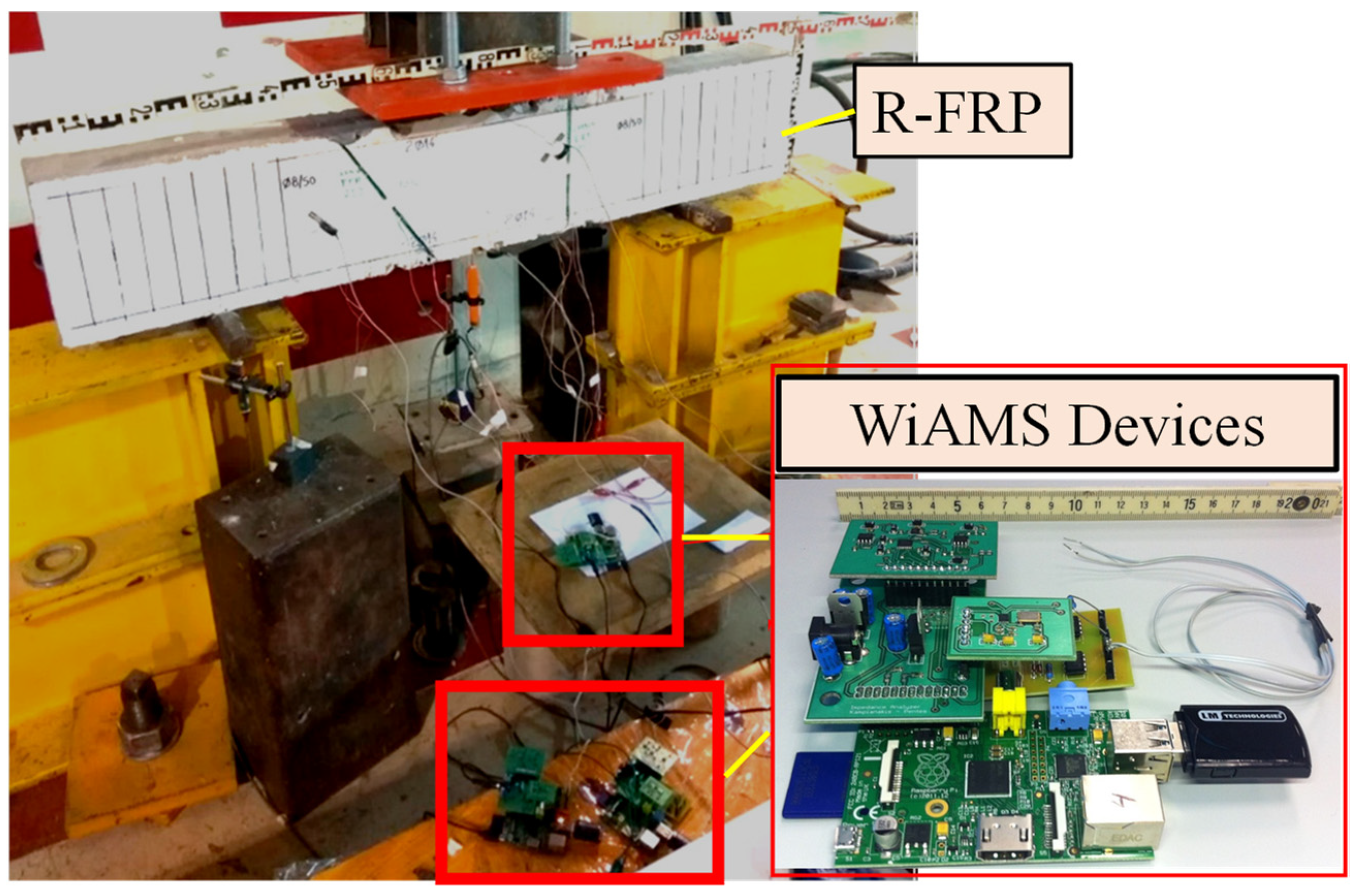
3.5. PZT Patches’ Installation
4. Results and Discussion
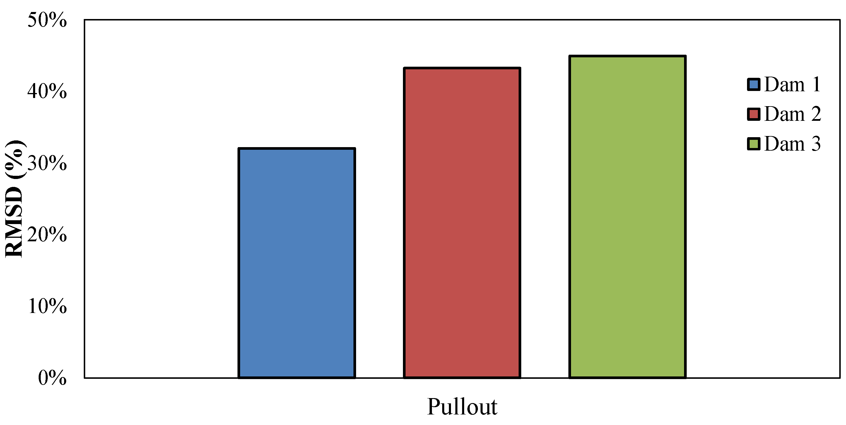
4.1. Pullout Test
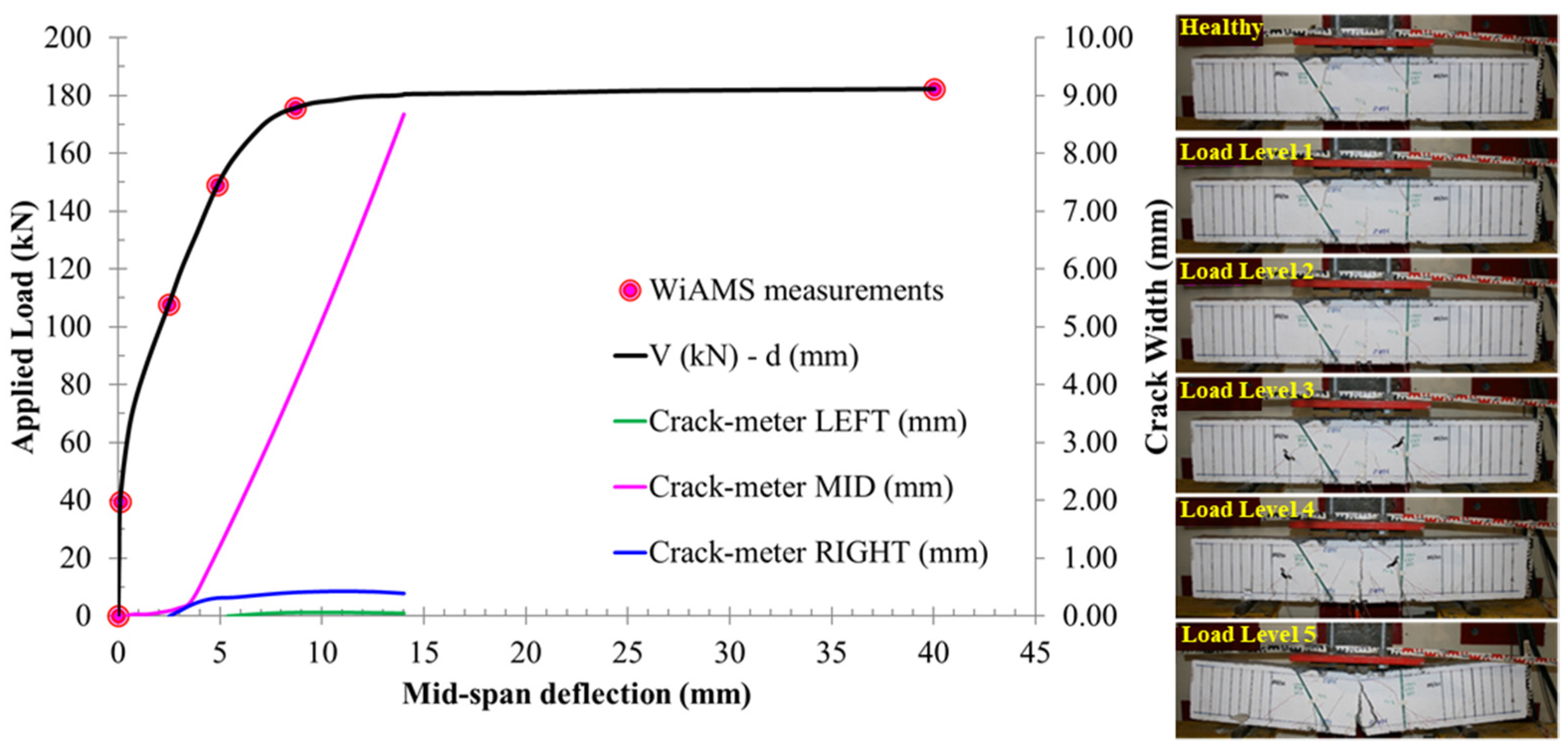
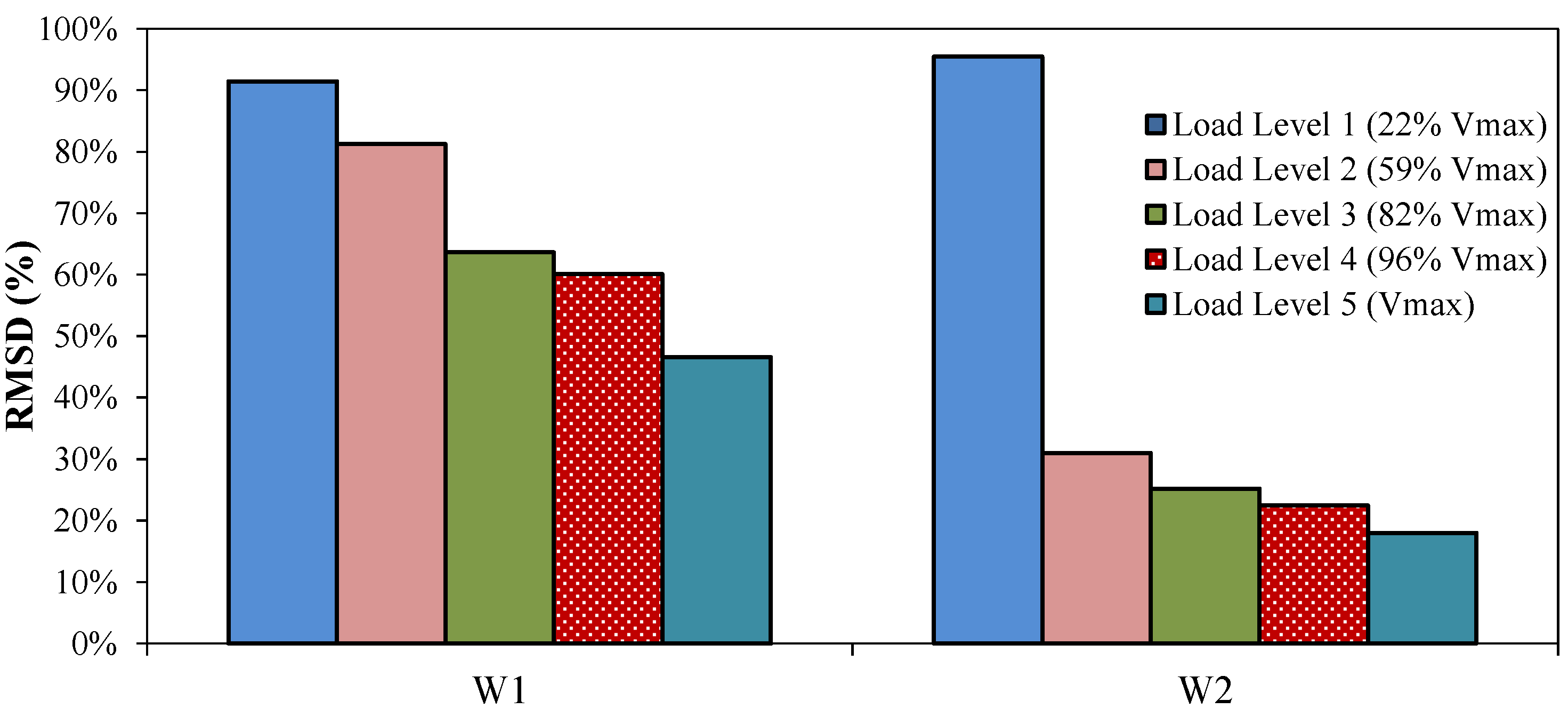
4.2. Deep Beam Loading Test
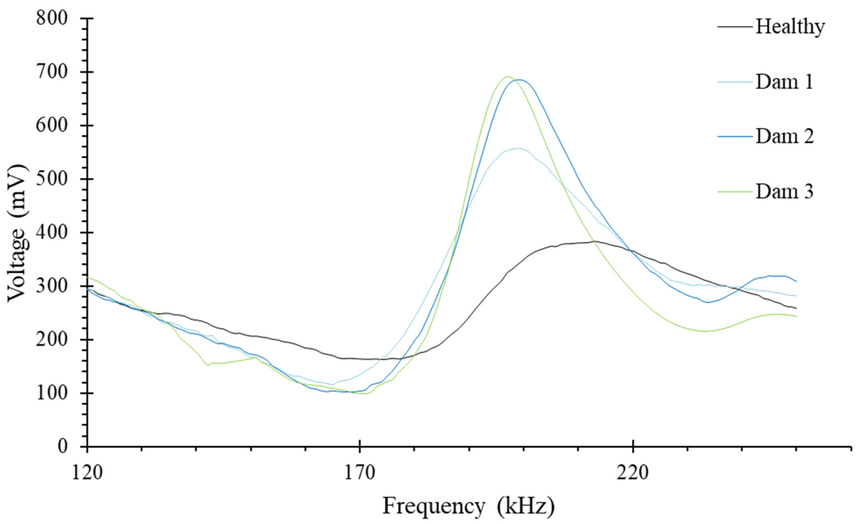
4.3. Data Analysis
4.4. Evaluation of the Efficacy of Retrofitting Technique
5. Conclusions
Author Contributions
Funding
Data Availability Statement
Conflicts of Interest
References
- Zhang, T.; Visintin, P.; Oehlers, D.J. Shear Strength of RC Beams with Steel Stirrups. J. Struct. Eng. 2016, 142, 04015135. [Google Scholar] [CrossRef]
- Zararis, P.D. Shear Compression Failure in Reinforced Concrete Deep Beams. J. Struct. Eng. 2003, 129, 544–553. [Google Scholar] [CrossRef]
- Godat, A.; L’Hady, A.; Chaallal, O.; Neale, K.W. Bond Behavior of the ETS FRP Bar Shear-Strengthening Method. J. Compos. Constr. 2012, 16, 529–539. [Google Scholar] [CrossRef]
- Azam, R.; Soudki, K.; West, J.S.; Noël, M. Behavior of Shear-Critical RC Beams Strengthened with CFRCM. J. Compos. Constr. 2018, 22, 04017046. [Google Scholar] [CrossRef]
- Karayannis, C.G.; Sirkelis, G.M. Strengthening and Rehabilitation of RC Beam–Column Joints Using Carbon-FRP Jacketing and Epoxy Resin Injection. Earthq. Engng Struct. Dyn. 2008, 37, 769–790. [Google Scholar] [CrossRef]
- Karayannis, C.G.; Naoum, M.C. Torsional Behavior of Multistory RC Frame Structures Due to Asymmetric Seismic Interaction. Eng. Struct. 2018, 163, 93–111. [Google Scholar] [CrossRef]
- Tsonos, A.G. Effectiveness of CFRP Jackets in Post-Earthquake and Pre-Earthquake Retrofitting of Beam-Column Subassemblages. Struct. Eng. Mech. 2007, 27, 393–408. [Google Scholar] [CrossRef]
- Lampropoulos, A.P.; Dritsos, S.E. Modeling of RC Columns Strengthened with RC Jackets. Earthq Engng Struct Dyn 2011, 40, 1689–1705. [Google Scholar] [CrossRef]
- Ma, C.-K.; Apandi, N.M.; Sofrie, C.S.Y.; Ng, J.H.; Lo, W.H.; Awang, A.Z.; Omar, W. Repair and Rehabilitation of Concrete Structures Using Confinement: A Review. Constr. Build. Mater. 2017, 133, 502–515. [Google Scholar] [CrossRef]
- Azam, R.; Soudki, K.; West, J.S.; Noël, M. Strengthening of Shear-Critical RC Beams: Alternatives to Externally Bonded CFRP Sheets. Constr. Build. Mater. 2017, 151, 494–503. [Google Scholar] [CrossRef]
- Ferreira, D.; Oller, E.; Marí, A.; Bairán, J. Numerical Analysis of Shear Critical RC Beams Strengthened in Shear with FRP Sheets. J. Compos. Constr. 2013, 17, 04013016. [Google Scholar] [CrossRef]
- Baggio, D.; Soudki, K.; Noël, M. Strengthening of Shear Critical RC Beams with Various FRP Systems. Constr. Build. Mater. 2014, 66, 634–644. [Google Scholar] [CrossRef]
- Aguilar, V. Shear Strength of Concrete Members: Challenges, Recent Developments and Possibilities. Adv. Civ. Eng. Technol. 2020, 4, 1–2. [Google Scholar] [CrossRef]
- Işık, E.; Ulutaş, H.; Harirchian, E.; Avcil, F.; Aksoylu, C.; Arslan, M.H. Performance-Based Assessment of RC Building with Short Columns Due to the Different Design Principles. Buildings 2023, 13, 750. [Google Scholar] [CrossRef]
- Pan, Z.; Li, B. Evaluation of Shear Strength Design Methodologies for Slender Shear-Critical RC Beams. J. Struct. Eng. 2013, 139, 619–622. [Google Scholar] [CrossRef]
- Papadopoulos, N.A.; Naoum, M.C.; Sapidis, G.M.; Chalioris, C.E. Cracking and Fiber Debonding Identification of Concrete Deep Beams Reinforced with C-FRP Ropes against Shear Using a Real-Time Monitoring System. Polymers 2023, 15, 473. [Google Scholar] [CrossRef]
- Bilotta, A.; Ceroni, F.; Di Ludovico, M.; Nigro, E.; Pecce, M.; Manfredi, G. Bond Efficiency of EBR and NSM FRP Systems for Strengthening Concrete Members. J. Compos. Constr. 2011, 15, 757–772. [Google Scholar] [CrossRef]
- Seo, S.-Y.; Feo, L.; Hui, D. Bond Strength of near Surface-Mounted FRP Plate for Retrofit of Concrete Structures. Compos. Struct. 2013, 95, 719–727. [Google Scholar] [CrossRef]
- Breveglieri, M.; Aprile, A.; Barros, J.A.O. Embedded Through-Section Shear Strengthening Technique Using Steel and CFRP Bars in RC Beams of Different Percentage of Existing Stirrups. Compos. Struct. 2015, 126, 101–113. [Google Scholar] [CrossRef]
- Li, P.; Wang, H.; Nie, D.; Wang, D.; Wang, C. A method to analyze the long-term durability performance of underground reinforced concrete culvert structures under coupled mechanical and environmental loads. J. Intell. Constr. 2023, 1, 9180011. [Google Scholar] [CrossRef]
- Said, M.; Adam, M.A.; Mahmoud, A.A.; Shanour, A.S. Experimental and Analytical Shear Evaluation of Concrete Beams Reinforced with Glass Fiber Reinforced Polymers Bars. Constr. Build. Mater. 2016, 102, 574–591. [Google Scholar] [CrossRef]
- Naoum, M.; Sapidis, G.; Papadopoulos, N.; Golias, E.; Chalioris, C. Structural Health Monitoring of Reinforced Concrete Beam-Column Joints Using Piezoelectric Transducers. In Proceedings of the International RILEM Conference on Synergising Expertise towards Sustainability and Robustness of Cement-Based Materials and Concrete Structures, Milos, Greece, 14–16 June 2023; Jędrzejewska, A., Kanavaris, F., Azenha, M., Benboudjema, F., Schlicke, D., Eds.; RILEM Bookseries. Springer Nature: Cham, Switzerland, 2023; Volume 43, pp. 945–956. [Google Scholar] [CrossRef]
- Turner, L.; Davies, V.C. Plain and reinforced concrete in torsion, with particular reference to reinforced-concrete beams. Sel. Eng. Pap. 1934, 1, 165. [Google Scholar] [CrossRef]
- Chalioris, C.E.; Papadopoulos, N.A.; Sapidis, G.; Naoum, M.C.; Golias, E. EMA-Based Monitoring Method of Strengthened Beam-Column Joints. In Proceedings of the International ISCRAM Conference, Omaha, NE, USA, 28–31 May 2023; pp. 853–873. [Google Scholar] [CrossRef]
- Alam, P.; Mamalis, D.; Robert, C.; Floreani, C.; Brádaigh, C.M.Ó. The Fatigue of Carbon Fibre Reinforced Plastics—A Review. Compos. Part B Eng. 2019, 166, 555–579. [Google Scholar] [CrossRef]
- Zhu, X.; Abe, H.; Hayashi, D.; Tanaka, H. Behavioral characteristics of RC beams with non-uniform corrosion along the reinforcement. J. Intell. Constr. 2023, 1, 9180019. [Google Scholar] [CrossRef]
- Chalioris, C.; Kosmidou, P.-M.; Papadopoulos, N. Investigation of a New Strengthening Technique for RC Deep Beams Using Carbon FRP Ropes as Transverse Reinforcements. Fibers 2018, 6, 52. [Google Scholar] [CrossRef]
- Bazli, M.; Abolfazli, M. Mechanical Properties of Fibre Reinforced Polymers under Elevated Temperatures: An Overview. Polymers 2020, 12, 2600. [Google Scholar] [CrossRef]
- Kytinou, V.K.; Gribniak, V.; Zapris, A.G.; Chalioris, C.E. An Innovative Health-Monitoring Approach for Fiber-Reinforced Polymer Debonding Diagnosis Through Pullout and Shear Tests. In Analytical and Experimental Methods in Mechanical and Civil Engineering; Springer: Cham, Switzerland, 2024; Volume 28, pp. 228–239. [Google Scholar] [CrossRef]
- Ju, S.; Li, D.; Jia, J. Experimental Investigation and Damage Evaluation of a Novel Bond Type Anchorage for Carbon Fiber Reinforced Polymer Tendons. J. Civ. Struct. Health Monit. 2023, 13, 117–132. [Google Scholar] [CrossRef]
- El-Sisi, A.A.; El-Emam, H.M.; El-Kholy, A.E.-M.I.; Ahmad, S.S.; Sallam, H.M.; Salim, H.A. Structural Behavior of RC Beams Containing Unreinforced Drilled Openings with and without CFRP Strengthening. Polymers 2022, 14, 2034. [Google Scholar] [CrossRef]
- Baena, M.; Jahani, Y.; Torres, L.; Barris, C.; Perera, R. Flexural Performance and End Debonding Prediction of NSM Carbon FRP-Strengthened Reinforced Concrete Beams under Different Service Temperatures. Polymers 2023, 15, 851. [Google Scholar] [CrossRef]
- Perera, R.; Gil, A.; Torres, L.; Barris, C. Diagnosis of NSM FRP Reinforcement in Concrete by Using Mixed-Effects Models and EMI Approaches. Compos. Struct. 2021, 273, 114322. [Google Scholar] [CrossRef]
- Pellone, L.; Ciminello, M.; Mercurio, U.; Apuleo, G.; Concilio, A. A Structural Health Monitoring System for Bond Line Flaws Detection on a Full-Scale Wingbox Section Demonstrator. Appl. Mech. 2024, 5, 36–57. [Google Scholar] [CrossRef]
- Ai, D.; Mo, F.; Yang, F.; Zhu, H. Electromechanical Impedance-Based Concrete Structural Damage Detection Using Principal Component Analysis Incorporated with Neural Network. J. Intell. Mater. Syst. Struct. 2022, 33, 2241–2256. [Google Scholar] [CrossRef]
- Ai, D.; Zhang, D.; Zhu, H. Damage Localization on Reinforced Concrete Slab Structure Using Electromechanical Impedance Technique and Probability-Weighted Imaging Algorithm. Constr. Build. Mater. 2024, 424, 135824. [Google Scholar] [CrossRef]
- Sapidis, G.M.; Kansizoglou, I.; Naoum, M.C.; Papadopoulos, N.A.; Chalioris, C.E. A Deep Learning Approach for Autonomous Compression Damage Identification in Fiber-Reinforced Concrete Using Piezoelectric Lead Zirconate Titanate Transducers. Sensors 2024, 24, 386. [Google Scholar] [CrossRef]
- Wang, Z.; Chen, D.; Zheng, L.; Huo, L.; Song, G. Influence of Axial Load on Electromechanical Impedance (EMI) of Embedded Piezoceramic Transducers in Steel Fiber Concrete. Sensors 2018, 18, 1782. [Google Scholar] [CrossRef]
- Naoum, M.C.; Papadopoulos, N.A.; Voutetaki, M.E.; Chalioris, C.E. Structural Health Monitoring of Fiber-Reinforced Concrete Prisms with Polyolefin Macro-Fibers Using a Piezoelectric Materials Network under Various Load-Induced Stress. Buildings 2023, 13, 2465. [Google Scholar] [CrossRef]
- Naoum, M.C.; Sapidis, G.M.; Papadopoulos, N.A.; Voutetaki, M.E. An Electromechanical Impedance-Based Application of Real-time Monitoring for the Load-Induced Flexural Stress and Damage in Fiber-Reinforced Concrete. Fibers 2023, 11, 34. [Google Scholar] [CrossRef]
- Khatir, A.; Capozucca, R.; Kathir, S.; Magagnini, E.; Benaissa, B.; Cuong-Le, T. An efficient improved gradient boosting for strain prediction in NSM FRP strengthened RC beam. Front. Struct. Civ. Eng. 2024; in press. [Google Scholar]
- Reddy, P.N.; Kavyateja, B.V.; Jindal, B.B. Structural Health Monitoring Methods, Dispersion of Fibers, Micro and Macro Structural Properties, Sensing, and Mechanical Properties of Self-sensing Concrete—A Review. Struct. Concr. 2021, 22, 793–805. [Google Scholar] [CrossRef]
- Perera, R.; Huerta, M.C.; Baena, M.; Barris, C. Analysis of FRP-Strengthened Reinforced Concrete Beams Using Electromechanical Impedance Technique and Digital Image Correlation System. Sensors 2023, 23, 8933. [Google Scholar] [CrossRef]
- Li, D.; Zhou, J.; Ou, J. Damage, Nondestructive Evaluation and Rehabilitation of FRP Composite-RC Structure: A Review. Constr. Build. Mater. 2021, 271, 121551. [Google Scholar] [CrossRef]
- Khatir, A.; Capozucca, R.; Khatir, S.; Magagnini, E.; Benaissa, B.; Le Thanh, C.; Wahab, M.A. A new hybrid PSO-YUKI for double cracks identification in CFRP cantilever beam. Compos. Struct. 2023, 311, 116803. [Google Scholar] [CrossRef]
- Providakis, C.; Tsistrakis, S.; Voutetaki, M.; Tsompanakis, J.; Stavroulaki, M.; Agadakos, J.; Kampianakis, E.; Pentes, G.; Liarakos, E. An Innovative Active Sensing Platform for Wireless Damage Monitoring of Concrete Structures. Curr. Smart Mater. 2016, 1, 49–62. [Google Scholar] [CrossRef]
- Mofidi, A.; Chaallal, O.; Benmokrane, B.; Neale, K. Experimental Tests and Design Model for RC Beams Strengthened in Shear Using the Embedded Through-Section FRP Method. J. Compos. Constr. 2012, 16, 540–550. [Google Scholar] [CrossRef]
- ACI (American Concrete Institute). Guide for the Design and Construction of Externally Bonded FRP Systems for Strengthening Concrete Structures; ACI-440.2R-08; American Concrete Institute (ACI): Farmington Hills, MI, USA, 2008; p. 76. [Google Scholar]

| Material | Mechanical Properties | |
|---|---|---|
| C-FRP rope SikaWrap FX-50C (Laminate) | Tensile strength (TS) | 2100 GPa |
| Elastic modulus in tension | 230 GPa | |
| Elongation at break in tension | 0.87% | |
| Sikadur 300 | TS | 45 MPa |
| Elastic modulus in tension | 3.5 GPa | |
| Sikadur 330 | TS | 30 MPa |
| Elastic modulus in tension | 4.5 GPa | |
| Sika Anchorfix 3+ | Compressive strength | 114 MPa |
Disclaimer/Publisher’s Note: The statements, opinions and data contained in all publications are solely those of the individual author(s) and contributor(s) and not of MDPI and/or the editor(s). MDPI and/or the editor(s) disclaim responsibility for any injury to people or property resulting from any ideas, methods, instructions or products referred to in the content. |
© 2024 by the authors. Licensee MDPI, Basel, Switzerland. This article is an open access article distributed under the terms and conditions of the Creative Commons Attribution (CC BY) license (https://creativecommons.org/licenses/by/4.0/).
Share and Cite
Papadopoulos, N.A.; Naoum, M.C.; Sapidis, G.M.; Chalioris, C.E. Resilient and Sustainable Structures through EMI-Based SHM Evaluation of an Innovative C-FRP Rope Strengthening Technique. Appl. Mech. 2024, 5, 405-419. https://doi.org/10.3390/applmech5030024
Papadopoulos NA, Naoum MC, Sapidis GM, Chalioris CE. Resilient and Sustainable Structures through EMI-Based SHM Evaluation of an Innovative C-FRP Rope Strengthening Technique. Applied Mechanics. 2024; 5(3):405-419. https://doi.org/10.3390/applmech5030024
Chicago/Turabian StylePapadopoulos, Nikos A., Maria C. Naoum, George M. Sapidis, and Constantin E. Chalioris. 2024. "Resilient and Sustainable Structures through EMI-Based SHM Evaluation of an Innovative C-FRP Rope Strengthening Technique" Applied Mechanics 5, no. 3: 405-419. https://doi.org/10.3390/applmech5030024
APA StylePapadopoulos, N. A., Naoum, M. C., Sapidis, G. M., & Chalioris, C. E. (2024). Resilient and Sustainable Structures through EMI-Based SHM Evaluation of an Innovative C-FRP Rope Strengthening Technique. Applied Mechanics, 5(3), 405-419. https://doi.org/10.3390/applmech5030024